

Page 1

Operator's Manual
Use and Care
Page 2

IMPORTANT: READ THIS MANUAL BEFORE USING NEW COMMERCIAL SLICER
It is of extreme importance to take a few minutes and read this booklet thoroughly before using
the new slicer. This will help you obtain the full benefits of the quality, convenience and safet y built
into this product. Used and maintained according to the following instructions, the slicer will give
you years of trouble free service. Keep this booklet in a handy location for future reference.
IMPORTANT SAFEGUARDS
When using electric appliances, basic safety precautions should always be followed including the
following:
1. READ ALL INSTRUCTIONS .
2. To protect against electrical hazards, DO NOT IMMERSE THE SLICER IN WATER OR ANY
OTHER LIQUID.
3. Unplug from outlet when not in use—also before putting on or taking off parts and before
cleaning.
4. Do not operate this slicer with a damaged cord or plug or after the slicer has been dropped or
damaged in any manner. Contact the nearest Service Agency for examination, repair or
5. Do not let the cord hang over the edge of a table or counter, or touch hot surfaces.
6. Remove all attachments from slicer before washing.
7. NEVER LEAVE SLICER UNATTENDED while unit is operating.
8. The use of attachments not recommended by the manufacturer may cause hazards.
9. Follow manufacturer's instructions for use of attachments to be used with slicer.
10. KEEP OUT OF REACH OF CHILDREN.
11. SAVE THESE INSTRUCTIONS .
The new slicer comes to you fully assembled and ready for use; however, the machine should be
inspected for any signs of shipping damage. Even though it is anew machine, the slicer should be
thoroughly cleaned and sanitized before using to ensure sanitary conditions—follow the
cleaning instructions found in this manual.
ASSEMBLY
1
Page 3

2
This safety information sheet is supplied
with the slicer. Familiarize yourself with
these guidelines and post the sheet near
the slicer as a reminder.
2
Page 4
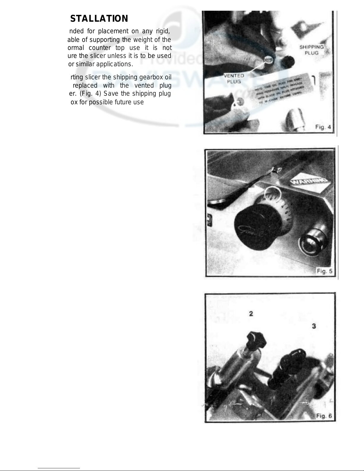
INSTALLATION
The slicer is intended for placement on any rigid,
level surface capable of supporting the weight of the
machine. For normal counter top use it is not
necessary to secure the slicer unless it is to be used
on board ship or for similar applications.
NOTE: Before starting slicer the shipping gearbox oil
plug should be replaced with the vented plug
supplied with slicer. (Fig. 4) Save the shipping plug
in the accessory box for possible future use
DISASSEMBLY FOR
CLEANING
CAUTION: Unplug slicer and set regulator knob to
"0" before cleaning or handling. (Fig. 5)
FOOD PUSHER REMOVAL
1. Slide platform to extreme forward position (toward
you).
2. Unscrew and remove knob at end of food pusher
shaft. (Fig. 6)
3. Slide food pusher up and off shaft. (Fig. 6)
3
Page 5

FOOD FENCE REMOVAL
1. Loosen lock knob (counter-clockwise.) (Fig. 7)
2. Slide fence off of platform. (Fig. 7)
PLATFORM REMOVAL
1. Unscrew (counter-clockwise) and remove platform knob. (Fig 81)
2. Pull platform assembly straight out and off of slicer. (Fig. 9)
KNIFEWIPER REMOVAL
NOTE: The knifewiper is located at the lower back side of knife in the
receiving area.
1. Unscrew and remove thumbscrew (counter-clockwise) (Fig. 10)
2. Remove knifewiper by pulling straight out.
4
Page 6

KNIFE SHARPENER REMOVAL
CAUTION: EXTREME CARE SHOULD BE USED WHEN REMOVING THE KNIFE
SHARPENER AS THIS WILL LEAVE A PORTION OF THE KNIFE EXPOSED.
1. Loosen the sharpener lock knob (on far side of sharpener, Fig. 11)
2. Pull sharpener straight up to its st op. (Fig. 12) DO NOT Unscrew knob.
3. Turn sharpener 1/2 turn clockwise. (Fig. 13)
4. Lift up to remove from slicer (Fig. 13)
KNIFE COVER REMOVAL
CAUTION: DO NOT TOUCH KNIFE. SHARP EDGES WILL CUT.
1. Platform should be removed as described earlier.
2. Unscrew (counter-clockwise) and remove knob and rod assembly. (Fig. 14)
3. Grasp knife cover by thumbscrews shown in figure 15.
4. Holding thumbscrews (Fig. 16) remove knife cover by pulling straight out and off of slicer.
5
Page 7

CLEANING
The slicer should be thoroughly cleaned and sanitized before using the first time and after
each day's operation or anytime the slicer is not to be used for an extended period of time.
Follow your companies sanitary standards as well as state and local health codes.
IMPORTANT: For your safety always wear protective cut-resistant gloves when cleaning
the knife or in the area of the knife.
UNPLUG slicer before cleaning.
NEVER use steel pads or abrasive cleaners.
1. Using a mild soap, hot water and a clean cloth carefully wash both sides of knife by
wiping outward from the center. Rinse knife in the same manner using another clean cloth
and fresh water.
2. Wash and rinse both sides of the knife cover. Re-install the knife cover.
3. Clean the knife sharpener. Be sure that the stones
are free of grease and food particles. Use the wire
brush supplied in the accessory box if necessary.
(Fig. 17)
4. Re-install the knife sharpener and tighten lock
knob.
DO NOT immerse the slicer base in water.
DO NOT direct spray cleaners at switch area or into
the openings of the machine.
5. Wipe all surfaces of the slicer with the mild soap solution and rinse.
6. Clean a!l remaining parts in the same manner.
DO NOT wash any slicer parts in a dishwasher.
To clean under the ASM-HD raise the lift lever and move it past the center position until it
locks. (Fig. 18) After cleaning pull the lift lever release knob and hold out (Fig. 19) then
slowly move the lif t lever back toward the front of the slicer lowering it back down.
6
Page 8

Reassemble the remaining parts to the slicer.
When installing the platform always be sure to tighten the
lock knob. The label at right appears on the machine as a
reminder. (Fig. 20)
ELECTRICAL POWER SUPPLY
The slicer should be placed close enough to the electrical
power supply so that an extension cord will not be
needed. The slicer is designed to be used on 115 Volt,
A.C., 60 Hz power source, as indicated on the Data Plate
which is affixed to the rear of the unit. (Fig. 21) BE SURE
THAT THE VOLTAGE IS THE SAME BEFORE
PLUGGING SLICER INTO OUTLET. To operate the unit
on other voltages, the unit must be returned to the factory
ALWAYS USE A PROPERLY GROUNDED THREE-
PRONG OUTLET TO REDUCE THE HAZARD OF
ELECTRICAL SHOCK.
NOTE: It is important that all electrical connections be
made in compliance with all applicable local electrical
codes as well as the latest edition of the National
Electrical Code.
OPERATION
SLICING—MODEL SM -HD OR MANUAL OPERATION OF MODEL
ASM-HD
1. Place platform drive engagement lever in the down (disengaged) position, (Fig. 22)
2. Set platform speed control knob to zero slices per minute. (Fig. 23)
7
Page 9

3. Pull platform all the way toward you until it reaches its stop.
4. With food pusher out of the way (stored in holder) place product to be cut on platform.
5. Adjust the food fence by loosening the knob and sliding the fence so that it is close to the
product but not pushing against it. Tighten the knob. (Fig. 24)
6. Place food pusher behind product to be cut. (Fig. 25)
7. Set regulator knob for desired slice thickness and start slicer. (If the slicer is equipped
with the regulator knob "shut-off" option, the motor can be turned ON and OFF with
the use of the regulator knob while power switch is in ON position ) ALWAYS TURN
POWER SWITCH TO "OFF" POSITION WHEN SLICER IS NOT IN USE.
8. Using platform reciprocating handle, move
platform back and forth for each slice. (Fig.
26) Be sure to push platform far enough
forward to complete the slice, then pull back
until the food being cut clears the cutting
edge of the knife.
The slicer is gravity fed; however, use of the
food pusher is important to prevent personal
injury, particularly when slicing small pieces of
food. NEVER FEED FOOD BY HAND;
ALWAYS USE FOOD PUSHER.
8
Page 10

SLICING—MODEL ASM -HD AUTOMATIC OPERATION
1. With power switch in OFF position, set platform speed control to zero slices per minute. (Fig. 23).
2. Pull platform all the way toward you until it reaches its stop.
3. Place food on platform, adjust fence and set food pusher in place. (Fig. 24 & 25)
4. Place platform drive engagement lever in up
(engaged) position. (Fig. 27)
5. Set regulator knob for desired slice thickness and
start slicer. (If the slicer is equipped with the
regulator knob "shut-off" option, the motor can
be turned ON and OFF with the use of the regulator
knob while power switch is in ON position.)
ALWAYS TURN POWER SWITCH TO "OFF"
POSITION WHEN SLICER IS NOT IN USE.
6. Turn platform speed control knob to ten (10) slices per minute. After platform drive engages platform, set
speed control to desired slices per minute.
NOTE: Slower speeds should be used for thick cuts or hard foods.
MAINTENANCE
SHARPENING THE KNIFE
1. SHUT OFF AND UNPLUG SLICER.
2. Turn regulator knob to zero.
3. Set platform speed control knob to zero. (ASM -HD only)
4. Place platform drive engagement lever
in the down (disengaged position.) (ASM -HD
only)
5. CAREFULLY clean knife removing all
grease and food particles to prevent clogg-
ing of sharpener stones.
6. While slicer is OFF loosen the sharpener
lock knob. (Fig. 28)
9
Page 11

7. Pull up (Do not unscrew) Sharpener using knob on top. Fig. 29)
8. Rotate sharpener clockwise one-half turn (180). (Fig. 30).
9. Push down (Fig. 30). Lock into position using lock knob. (Fig. 28)
Plug in and turn slicer ON. DO NOT TOUCH KNIFE. Let stone grind knife for five (5)
10.
seconds or until desired edge is obtained.
Push in button for deburring stone (Fig. 31) and hold in for 2-3 seconds until edge is smooth
11.
and free of burrs.
When the proper edge has been obtained through sharpening and deburring shut OFF and
12.
unplug slicer.
13. Return sharpener to its original stored position and tighten lock knob. (Fig. 28)
IMPORTANT: After sharpening, clean both sharpener and knife. Before slicing again be sure
that all steel particles from grinding have been removed to prevent contamination of food.
NOTE: A knife sharpening guide sheet is supplied with the slicer. Keep it in a handy location for
future reference.
TRANSMISSION AND GEAR MAINTENANCE
The slicer is equipped with a gear driven transmission and contains special gear oil. The gear oil
should not need changing, unless the transmission or motor has been removed. Consult a factory
authorized service agency or the factory for gearbox maintenance information.
10
Page 12

LUBRICATION
To insure continued smooth operation of sliding parts use the oil supplied in the accessory
box or a light mineral oil as follows:
1) Apply about ten drops of oil to the platform shaft about once per month. (Fig. 32)
Apply 2-3 drops of oil to the food pusher shaft and the knife cover rod after each washing.
2)
(Fig. 33)
WEAR ADJUSTMENT
After several years of operation and many sharpenings of the knife, it may be necessary to have
the regulator plate adjusted closer to the knife. Contact the factory authorized service agency or
the factory if this service becomes necessary as this service must be performed by an authorized
technician.
11
Page 13

REPLACEMENT PARTS
MODELS: SM—HD & ASM—HD
KEY
PART NO. NAME/DESCRIPTION
NO.
401
23-SM -1401 Base 1 447 9-SM -1447 Regulator Knob 1
402
23-SM -1402 Regulator Plate 1 454 8-SM -1561 Nut 3
403
23-SM -1403 Bracket: Regulator Plate 1 461 6-6-2192 Rubber Boot: Switch 1
404
8-SM -1404 Screw: Reg. Plate Brkt. 2 462 5-6-4581 Switch Guard 1
405
8-SM -1405 Washer: Reg. Plate Brkt. 2 463 6-SM -1463 Foot (SM-HD) 4
407
9-SM -1407 Support Post: Reg. Plt. 1 465 8-SM-1465 Platform Rail 1
408
9-SM -1408 Knob: Knife Cover 1 466 8-SM -1466 Screw: Platform Shaft 2
409
9-SM -1409 Rod: Knife Cover 1 467 8-SM -1467 Washer: Platform Shaft 2
410
9-SM -1410 Extension: Knife Shaft 1 468 7-SM -1468 Rubber Bumper 2
411
9-SM -1411 Shaft: Knife 1 469 9-SM -1469 Extension: Platform Shaft 1
412
8-SM -1412 Retaining Ring: Worm Gear 1 470 8-SM -1470 Bumper Spring: Platform Shaft 1
413
8-SM -1413 Spacer: Worm Gear 1 471 9-SM -1471 Platform Shaft 1
414
9-SM -1414 Worm Gear: Knife Drive 1 472 1-SM -1472 Platform Carriage 1
415
7-SM -1415 Seal: Knife Hub 1 473 5-6-1501 Switch: 115 Volt 1
416
6-SM -1713 Pad: Knife Drive Gear 3 * 5-6-1507 Switch: 220 Volt 1
417
4-SM -1696 Knife Hub (Std Knife) 1 474 5-SM -1503 Running Light: 115 Volt 1
* 4-SM -1698 Knife Hub (Long Taper) 1 * 5-SM-1300 Running Light: 220 Volt 1
** 30-SM -1696 Knife Hub Assembly: (Std Knife)
** 30-SM -1698 Knife Hub Assembly: (Lg Taper)
(Inc: 411-422, 606,607) 1 * 5-SM- 860 Capacitor: 220 Volt 1
418
8-SM -1418 Bearing: Knife 2 477 8-SM -1477 Bracket: Capacitor 1
419
8-SM -1419 Spacer: Knife Bearing 1 478 5-SM -1239 Cordset: 115 Volt 1
420
7-SM -1420 Bearing Retainer 1 479 8-SM -1240 Wire Clamp: Cordset 1
421
8-SM -1421 Nut: Knife Shaft 1 483 9-SM -1483 Handle: Food Pusher 1
422
8-SM -1422 Set Screw: Knife Shaft 1 493 23-SM -1493 Bracket: Platform 1
423
9-SM -1423 Knife: Stainless Steel (Std) 1 494 9-SM -1494 Handle: Platform 1
* 9-SM -1712 Knife: S/S (Long Taper) 1 * 8-SM-1495 Screw: Handle 2
424
8-SM -1424 Screw: Standard Knife 1 497- 9-SM -1497 Roller Bracket: Platform 1
* 8-SM -1032 Screw: Long Taper Knife 1 ** 30-SM -1497 Roller Brkt. Assy.: Inc. Roller 1
425
8-SM -1425 Spacer: Knife Cover 1 504 23-SM -1504 Sharpener Bracket 1
426
23-SM -1426 Knife Cover 1 505 8-SM -1505 Washer: Sharpener Brkt 1
427
8-SM -1427 Thumbscrew: Knife Cover 2 506 8-SM -1506 Screw: Sharpener Brkt 1
428
8-SM -1568 Screw: Motor Cover 2 507 8-SM -1542 Lug: Sharpener Brkt 1
429
23-SM -1429 Motor Cover 1 508 8-SM -1508 Stop Nut: Sharpener Brkt. 1
430
8-SM -1430 crew: Motor Mounting 4 509 9-SM -1509 Rod: Lock Knob 1
431
8-SM -1431 Washer: Mtr. Mtg. Screw 4 510 9-SM-1510 Shaft: Sharpener Frame 1
432
30-SM -1697 Motor Assy: 115V, 50/60 HZ 1 511 8-SM -1557 Stop Screw: Shrpnr Frm 1
* 30-SM -1430 Motor Assy: 220V, 50/60 HZ 1 512 8-SM -1512 Jam Nut: Stop Screw: 1
433
7-SM -1433 Seal: Motor Shaft 1 513 23-SM -1513 Sharpener Housing 1
434
7-SM -1434 Gasket: Motor 1 ** 30-SM -1513 Sharpener Assy, Complete 1
435
9-SM -1717 Drive Gear 1 514 8-SM -1514 Washer: Sharpener Hsg. 1
436
8-SM -1436 Key: Drive Gear 1 515 8-SM -1515 Nut: Sharpener Hsg. 1
437
8-SM -1437 Spacer: Spring 1 516 9-SM -1516 Knob: Sharpener Hsg. 1
438
8-SM -1438 Spring: Drive Gear 1 580 8-SM -1525 Nut: Sharpener Frame 1
439
8-SM -1439 Retaining Nut: Mtr. Shaft 1 581 8-SM -1021 Retaining Ring: Stone Shaft 2
440
9-SM -1440 Knife Wiper 1 582 9-SM -1705 Sharpener Frame 1
441
8-SM -1441 Thumb Screw: Knife Wiper 1 583 8-SM -1523 Spring: Stone Shaft 2
442
9-MM-2099 Strain Relief Bushing 1 584 9-SM-1721 Shaft: Sharpening Stone 1
443
9-SM -1443 Bushing: Regulator Knob 1 585 9-SM -1722 Button: Deburring Stone 1
445
9-SM -1445 Ratchet Pin Assy. W/ Jam Nut 1 586 8-SM -1723 Set Screw: Dbrg Stone Button 1
QTY
PER
MACH.
KEY
PART NO. NAME/DESCRIPTION
NO.
464 9-SM -1559 Oil Plug: Drain 1
* 8-SM -1504 Push-On Fastener: Light 1
476 5-SM -1476 Capacitor: 115 Volt 1
QTY
PER
MACH.
GENERAL SLICING/RED GOAT DISPOSERS
Page 14

MAC
KEY
MACH.
1
1
2
1
1
1
1
2
1
REPLACEMENT PARTS
MODELS: SM—HD & ASM—HD
KEY
NO.
PART NO. NAME/DESCRIPTION
QTY
PER
NO.
PART NO. NAME/DESCRIPTION
QTY
PER
587 9-SM-1724
588 9-SM-1531
589 9-SM-1535
598 30-SM-1623
599 4-SM-1725
600 8-SM-1726
601 8-SM-1727
602 30-SM-1443
604 8-SM-1451
605 8-SM-1456
606 8-SM-1728
607 4-SM-1729
608 9-SM-1559
*
9-SM-1560 Oil Plug: Vented
616 8-SM-1450
617 1-SM-1567
618 1-SM-1448
619 9-SM-1473
620 9-SM-1462
621 8-SM-1551
622 8-SM-1446
623 8-SM-1455
624 8-SM-1730
625 8-SM-1731 Jam Nut: Set Screw
626 9-SM-1452
627 8-SM-1459
628 8-SM-1460 Nut: Pivot Pin
629 8-SM-1458
630 9-SM-1461
631 9-SM-1453 Worm Follower
632 8-SM-1454 Retaining Ring: Worm Follower
633 8-SM-1732
634 8-SM-1541 Screw: Roller Bracket
636 9-SM-1274
637 8-SM-1539
638 8-SM-1488
639 9-SM-1489
640 9-SM-1484
641 9-SM-1490
642 23-SM-1480 Food Pusher Arm
644 8-SM-1482
645 23-SM-1481 Food Pusher w/ Spikes (SM -HD)
* 9-SM-1125 Spike: Food Pusher 17
* 6-SM-1486 Nylon Rider: Food Pusher 5
* 6-SM-1487 Rubber Spacer: Food Pusher 1
646 23-SM-1554
647 23-SM-1491 Platform
648 9-SM-1564
653 8-SM-1016 Jam Nut: Stone Shaft
654 4-SM-1734 Bottom Cap: Reg. Plate
Shaft: Deburring Stone 1 655 8-SM-1733 Bumper Spring: Platform 1
Deburring Stone 1
Sharpening Stone 1 656 8-SM-1117 Screw: Capacitor Clamp 1
Bottom Cover Assy 1 658 6-SM-1540 Roller Assy: Platform 2
Cover Plate: Reg. Mech. 1 659 8-SM-1735 Washer: Platform Shaft Ext. 1
Rivet: Knife Wiper 1
Set Screw: Reg. Worm 1
Regulator Worm Assy 1
Washer: Reg. Worm 1
Screw: Reg. Worm 1
Screw: Mtg. Ring 3
Mounting Ring: Knife Gr. 1
Oil Plug: Shipping 1
Pivot Pin Assy: Reg. Plt. Brkt. 1
Bracket: Regulator Slide 1
Regulator Slide 1
Stop Plate: Reg. Slide 1
Brass Bushing: Reg. Slide 2
Screw: Reg. Slide 2
Limit Screw: Reg. Slide 1
Set Screw: Reg. Slide 1
Set Screw: Reg. Slide 1
Regulator Plate Bracket 1
Screw: Spring 2
Washer: Pivot Pin 1
Spring: Worm Follower 1
Mtg Screw: Reg. Slide Brkt 3
Knob: Platform 1
Stud: Platform Knob 1
Screw: Food Pusher Brkt 2
Bracket: Food Pusher 1
Shaft: Food Pusher 1
Knob: Food Pusher Shaft 1
Stud: Food Pusher Handle 1
Adjustment Fence 1
Knob: Adjustment Fence 1
1
1
*not illustrated
**not illustrated
Carriage
as assembly
GENERAL SLICING/RED GOAT DISPOSERS
Page 15

GENERAL SLICING/RED GOAT DISPOSERS
Page 16

REPLACEMENT PARTS
1
2
1
1
1
1
4
1
1
2
2
1
4
4
MODEL: ASM—HD
KEY
PART NO.
NO.
300 1-SM-1593 Base (ASM -HD) 1
301 1-SM-1569 Carriage: Platform 1
302 1-SM-1603
303 8-SM-1594 Lever, Engagement 1
304 4-SM-1600 Oscillation Arm 1
305 9-SM-1709 Food Pusher W/spikes 1
306 9-SM-1638
307 6-SM-1695 Foot (ASM -HD) 4
308 8-SM-1582 Retaining Ring: 2
309 8-SM-1609 Key: Pivot Arm Assy. 1
310 8-SM-1584 Bearing: Oscillation Arm 1
311 8-SM-1586 Bushing: Pivot Arm 2
312 4-SM-1623 Bottom Cover 1
313 2-SM-1606 Motor (D.C.) 1
30-SM-1606 Gear Motor Assy. 1
314 9-SM-1589 Gear Box Assembly 1
315 9-SM-1574 Spring: Oscillation Arm 1
316 9-SM-1736 Spring: Lift Lev. Rel. Pin 1
317 9-SM-1570 Spring: Carriage 2
318 8-SM-1657 Stud: Oscillation Arm 2
319 9-SM-1632 Roller: Lift Lever 1
320 8-SM-1585 Screw: Oscillation Arm 1
321 8-SM-1607 Pivot Pin: Connecting Arm 1
322 8-SM-1573
323 8-SM-1572 Engagement Cam Pin * 1
324 9-SM-1575 Spindle: Roller Bushing 1
325 9-SM-1576 Roller Bushing: 1
326 4-SM-1587 Pivot Arm Assy. 1
327 4-SM-1580 Connecting Arm 1
328 8-SM-1737 Key: D.C. Motor 1
329 4-SM-1658
330 9-SM-1707
331 8-SM-1651 Spacer: Osc. Arm 2
332 8-SM-1634 Clamp Block: Lift Lever 1
333-
8-SM-1648 Bearing Retainer 1
334 8-SM-1605 Stud: Housing Assembly 4
335 8-SM-1739 Release Pin: Lift Lever 1
336 9-SM-1740
337 8-SM-1578 Spacer: Connecting Arm 2
338 8-SM-1738
339 8-SM-1741
QTY
PER
NAME/DESCRIPTION MACH.
Support: Oscillation Arm
(ASM -HD)
Knob: Lift Lever
Connecting Arm
(Inc. 314)
Support
Bushing: Oscillation Arm
Oscillation Arm
Cover Plate: Oscillation
Arm Sup.
Lift Lever
Support
Knob: Lift Lev. Rel. Pin
Screw: DC Motor
Mounting
Washer: Gearbox
Mounting
KEY
PART NO.
NO.
340 8-SM-1742 Lockwasher: Gearbox 4
341 8-SM-1743 Nut: Gearbox Mounting 4
342 8-SM-1592 Screw: Gearbox Mounting 4
343 5-SM-1708 Brush Assy.: DC Motor 2
344 9-SM-1744
345 8-SM-1604
346 8-SM-1647 Screw: Bearing Retainer 2
347 8-SM-1598 Screw: Roller Bushing 1
348 8-SM-1597 Washer: Rlr Bush. 1/4
349 8-SM-1595 Set Screw: Engage.Lever 1
350 8-SM-1571 Screw: Carriage 2
351 8-SM-1577 Screw: Oscillation Arm 1
352 8-SM-1599 Set Screw: Oscillation Arm 2
353 8-SM-1745 Jam Nut: Oscillation Arm 2
357 30-MM-2085 Speed Control: D.C. Motor 1
358 8-SM-1655 Nut: Osc. Arm Sup/ 2/2
359 8-SM-1431 Washer: Clamp Block 2
360 8-SM-1583 Washer: Connecting Arm 2
362 8-SM-1596 Engagement Bracket 1
363 30-MM-2086 Potentiometer W/Wires
364 9-SM-1616 Label: Control 1
365 5-6-1626 Circuit Breaker 1
366 5-MM-2060 Knob: Speed Control 1
368 8-SM-1276
369 8-SM-1640 Screw: Bottom Cover 4
370 8-SM-1635 Stop Pin: Lift Lever 1
371 8-SM-1637 Screw: Lift Lev. Clamp BIk 2
372 8-SM-1633
377 8-SM-1659
378 8-SM-1652
379 8-SM-1591 Screw: Pivot Arm Assy. 1
380 8-SM-1590 Washer: Pivot Arm Assy. 1
381 8-SM-1076 Slide Screw: Carriage 1
NAME/DESCRIPTION
Mounting
Cap: DC Motor Brush
Set Screw: Oscillation
Arm Support
Spindle
SpdI/Btm Cvr.
Roller Bush.
Set Screw
Clamp BIk
Nut: Housing Assy. Stud
Pin: Lift Lvr Rlr/
Engage.Lvr
Screw: Oscillation Arm
Support
Washer: Oscillation
Arm Sup Screw
QTY
PER
MACH.
2/1
GENERAL SLICING/RED GOAT DISPOSERS
Page 17

GENERAL SLICING/RED GOAT DISPOSERS
 Loading...