

Page 1

OPERATOR'S MANUAL
Operation
9
MODEL SMA12L SLICER
INTRODUCTION
The Model SMA12L Slicer is designed for counter top use. It slices boneless products such as ham, poultry, beef and cheese to
desired thickness.
IMPORTANT: READ THIS MANUAL BEFORE USING THE SLICER.
It is important to read this manual thoroughly before using the slicer. This will help you obtain the full benefits of the quality,
convenience and safety built into this product. Used and maintained according to the following instructions, the slicer will provide
years of trouble-free service. Keep this booklet in a convenient location for future reference.
Safety
General Description
Unpacking
Cleaning
Electrical Requirements 8
2
3
4
4
Lubrication 11
Maintenance 11
Parts Replacement and Service 13
Page 2

SAFETY
RECOGNIZE SAFETY INFORMATION. This is the safety-alert symbol.
When you see this symbol on your machine or in this manual, be alert to
the potential for personal injury.
Follow the recommended precautions and safe operating practices.
UNDERSTAND SIGNAL WORDS. Signal words (DANGER, WARNING and
CAUTION) appear with the safety-alert symbol in this manual and on safety
labels on the machine to identify the level of hazard seriousness.
DANGER indicates a hazard that WILL result in severe personal injury or
death.
WARNING indicates a hazard or unsafe practice which COULD result in
severe personal injury or death.
CAUTION indicates hazards or unsafe practices which COULD result in
minor personal injury or equipment damage.
READ ALL INSTRUCTIONS
Read this operator's manual before using the machine. Failure to follow
the instructions provided could result in personal injury or equipment
damage.
KEEP OUT OF REACH OF CHILDREN
This slicer is intended for commercial use only.
DO NOT OPERATE WITHOUT KNIFE COVER. Do not turn the machine
on unless the knife cover is in place.
DO NOT FEED FOOD BY HAND. Always use the foodpusher.
KEEP HANDS AWAY FROM KNIFE. Never touch the knife with your
hand.
DO NOT CATCH FOOD WITH YOUR HANDS. Let sliced food fall onto the
receiving area.
DO NOT OPERATE IF DAMAGED. Do not operate this slicer with a
damaged cord or plug, or if the slicer has been dropped or damaged in any
manner. Contact the nearest factory-authorized service center for
examination, repair or adjustment. (Refer to the service center list included
in the Owner's Information Packet.)
Do not allow the cord to touch hot surfaces. Do not allow the cord to hang
over the edge of a table or counter.
DO NOT LEAVE SLICER UNATTENDED. Never leave the slicer
unattended while the unit is operating.
UNPLUG SLICER. Set the regulator knob to "0" and unplug the slicer from
the outlet when not in use, before cleaning or removing jams, and before
attaching or removing this knife sharpener.
DO NOT IMMERSE
Do not place the slicer in water or any other liquid.
ATTACHMENTS
Do not use attachments not recommended by the manufacturer.
Follow the manufacturer's instructions for use of attachments.
SAVE THESE INSTRUCTIONS
Keep this manual in a convenient location for future reference.
2
Page 3
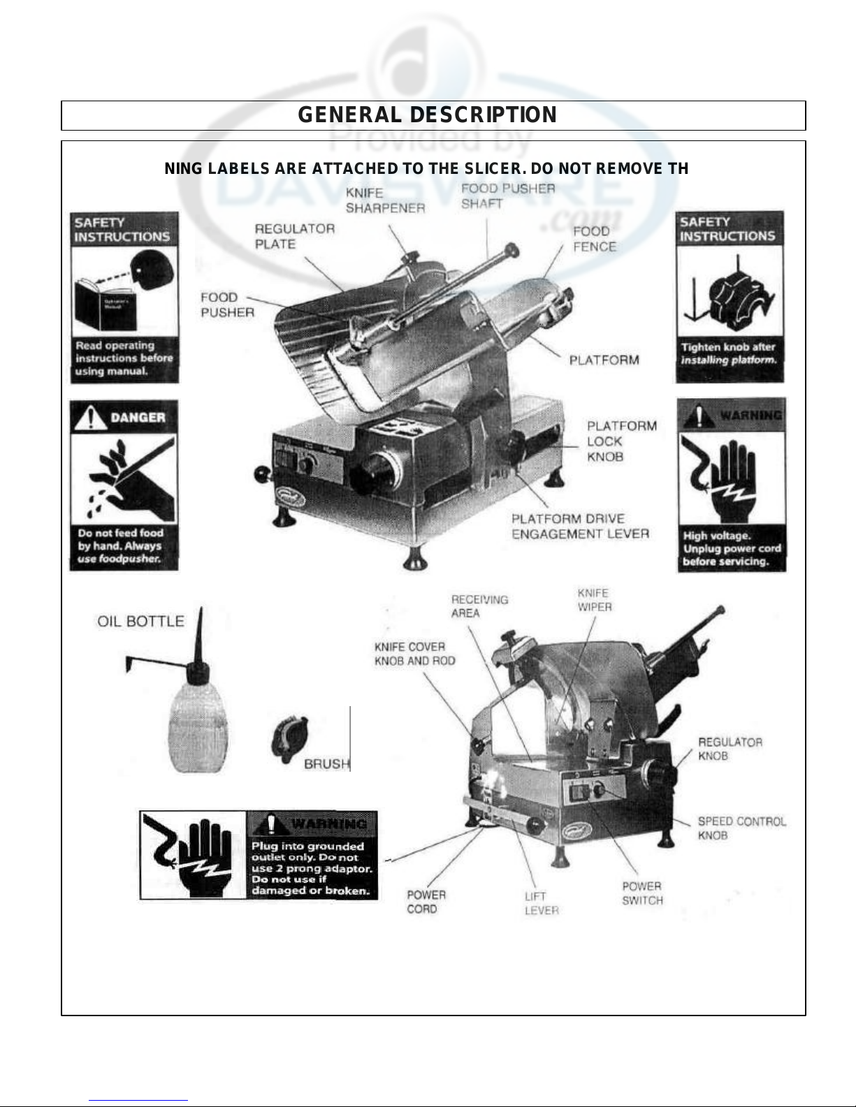
GENERAL DESCRIPTION
THESE WARNING LABELS ARE ATTACHED TO THE SLICER. DO NOT REMOVE THEM.
3
Page 4

UNPACKING AND ASSEMBLY
UNPACKING
The slicer comes fully assembled and ready for use; however, inspect
the shipping carton and its contents for shipping damage. If you detect
shipping damage to any of the contents of the carton, notify your carrier.
Remove the packing materials and take out the loose components (oil
bottle, brush, etc.), before removing the slicer from the carton. If there
are any parts missing, notify us immediately by calling the number on
the slicer.
CAUTION: The slicer should be installed on a level counter
top strong enough to safely support its weight.
The slicer should be thoroughly cleaned and sanitized (See Page 4)
before using to ensure sanitary conditions.
CLEANING
Clean and sanitize the slicer before using the first time, after each
use, and before slicing different types of food products. Follow
company, local, and state health/sanitation codes.
WARNING: Set the regulator knob to "0" and unplug the
slicer before cleaning or handling.
Do NOT use caustic or abrasive cleaners.
Do NOT spray cleaning materials or water toward the power switch,
the regulator knob, or the openings of the machine.
DISASSEMBLY FOR CLEANING Knife
Wiper
1. Remove the two thumbscrews by turning them
counter-clockwise.
2. Remove the knife wiper.
3. Wash the knife wiper in hot, soapy water.
4
Page 5
CLEANING (continued)
clockwise) and remove knob at end of food pusher
FOOD FEN
CE REMOVAL
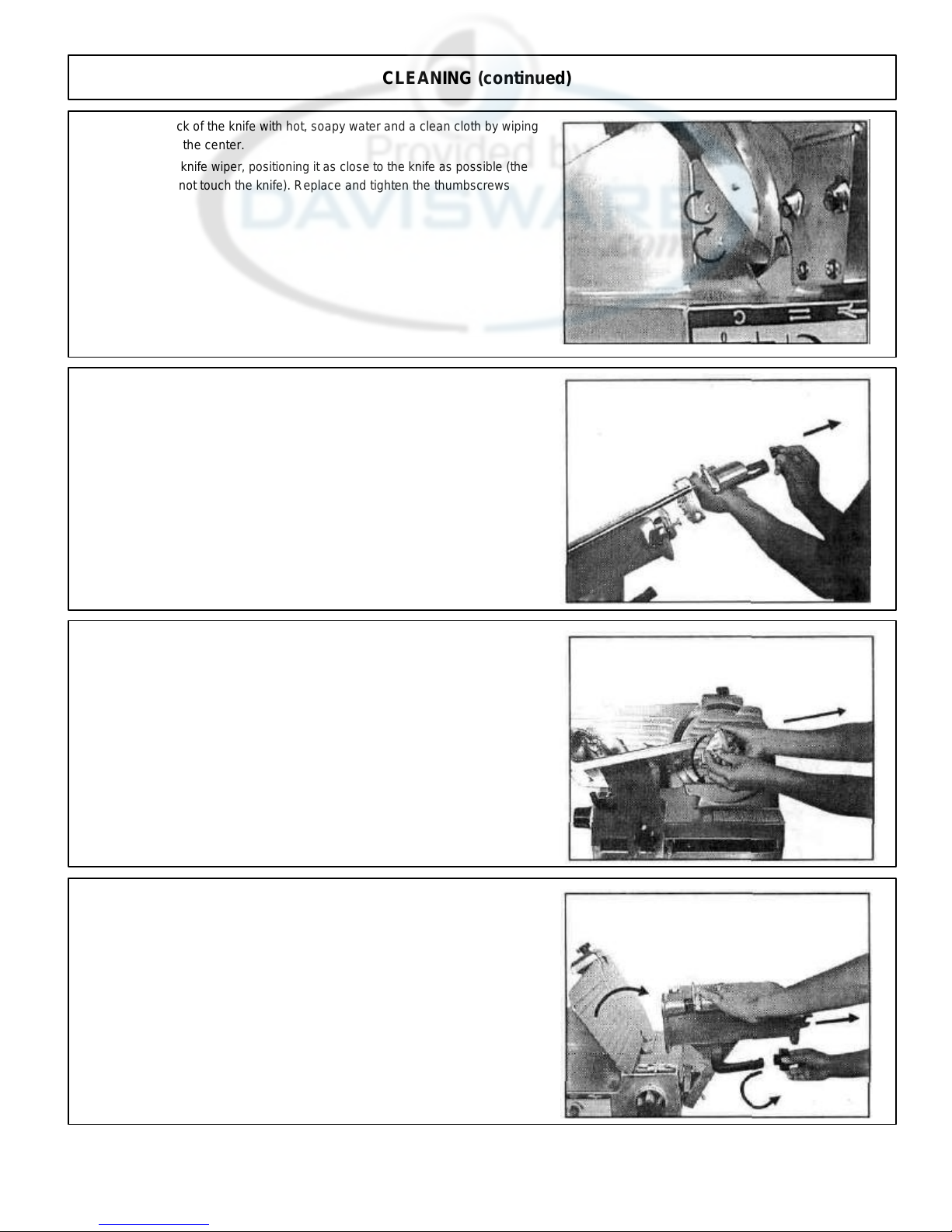
Clean the back of the knife with hot, soapy water and a clean cloth by wiping
4.
outward from the center.
Re-install the knife wiper, positioning it as close to the knife as possible (the
5.
wiper should not touch the knife). Replace and tighten the thumbscrews
clockwise.
FOOD PUSHER REMOVAL
1. Slide platform to extreme forward position (toward you).
Unscrew (counter-
2.
shaft.
3. Slide food pusher up and off shaft.
1. Loosen lock knob (counter-clockwise).
2. Slide fence off of platform.
REPOSITIONING PLATFORM
1. Remove the platform lock knob by turning it counter-clockwise.
2. Tilt the platform away from regulator plate (toward you).
5
Page 6

CLEANING (continued)
KNIFE SHARPENER REMOVAL
WARNING: Use protective cut -resistant gloves when removing or
reassembling the knife sharpener.
1. Remove the knife sharpener by lifting it straight up and
rotating it 90° clockwise.
2. Continue lifting straight up and out of mounting bracket.
KNIFE COVER REMOVAL
WARNING: Use protective cut -resistant gloves when
removing or reassembling the knife cover.
1. Remove the knife cover knob and rod assembly by turning it
counter-clockwise.
2. Push the knob and rod assembly in sharply against the knife
cover to dislodge it.
3. Remove the knife cover.
WASH ALL SURFACES
1. Clean all surfaces and parts of the slicer with hot, soapy water and a
clean cloth.
2. Clean the foodpusher shaft to remove food juices and ensure smooth
operation.
WARNING: Always use protective cut -resistant gloves when
cleaning the knife.
3. Clean the knife front with hot, soapy water and a clean cloth by wiping
outward from the center.
To clean under slicer, raise the lift lever and move it past the center position
until it rests against stop.
After cleaning, pivot lever back around to lower slicer.
6
Page 7

CLEANING (continued)
REASSEMBLY
Knife Cover
1. Re-install the knife cover by positioning it in the center of the
knife hub, rotating it slightly back and forth until it nests over
blade.
Note: The grooves on the front of the knife cover should be
horizontal, as on the regulator plate.
2. Replace the knob and rod assembly, and tighten by turning it
clockwise until snug.
Note: Do not overtighten.
Knife Sharpener
1. Position sharpener as shown and slide the sharpener shaft into
the mounting bracket, until stop is reached.
2. Turn counter-clockwise 90° and continue pushing down until
second stop is reached.
Note: The sharpening and deburring stones should be behind
blade and not in contact.
Platform Assembly
1. Tilt the platform back toward regulator plate, and replace and
tighten the lock knob by turning it clockwise.
7
Page 8

FOOD FENCE
CLEANING (continued)
1. Slide fence onto platform.
2. Tighten lock knob (clockwise.)
FOOD PUSHER
1. Slide food pusher onto shaft.
2. Reattach knob at end of food pusher shaft (clockwise).
ELECTRICAL REQUIREMENTS
Use a properly grounded three-prong outlet to reduce the hazard of
electrical shock.
The slicer should be placed close enough to the electrical power supply
so that an extension cord will not be needed. It is designed to be used
on 115 Volt, A.C., 60 Hz power source, as indicated on the Data Plate
affixed to the back of the unit. Be sure that the voltage is the same
before plugging the slicer into the outlet. To operate the unit on other
voltages, the slicer must be returned to the factory for modification.
All electrical connections must be made in compliance with all
applicable local electrical codes , as well as the latest edition of the
National Electrical Code (NFPA 70).
8
Page 9

OPERATION
Clean and sanitize the slicer before using the first time, after each
use, and before slicing different types of food products. Follow
company, local, and state health/sanitation codes.
CAUTION: Do not cut products that contain bone or froz en
product.
1. Plug the power cord into a grounded three-prong outlet. (See
Electrical Requirements, Page 8).
MANUAL OPERATION INSTRUCTIONS
2. Pull the platform assembly to the front of the slicer (toward you).
3. Raise the foodpusher to its open position.
4. Place the product to be sliced on the platform against the regulator
plate, slide the foodpusher up the shaft, and lower it against the
product.
5. Set the regulator knob to the desired slice thickness.
6. Push green button (I) to start blade.
9
Page 10

OPERATION
ff), set platform
gradually increasing slice/min. increments
DANGER: Do not feed food by hand. Always use the
foodpusher.
• DANGER: Keep your hands away from the back of the cutting
7. Holding the platform handle with your right hand, move the platform
of the knife.
forward to complete the slice, and back until the product clears the cutting
edge of the knife. Repeat until desired quantity is cut. (The slicer is
gravity-fed, so it is not necessary to exert force or pressure against the
foodpusher.)
8. Press red button (0) to stop blade.
9. Set regulator knob to "0".
Clean the slicer after each operation, as described in the Cleaning
Section.
AUTOMATIC OPERATION INSTRUCTIONS
With power switch in OFF position (center run light o
1.
speed control to zero slices per minute.
2, Pull platform all the way toward you until it reaches its stop.
3. Place food on platform, adjust fence and set foodpusher in place.
4. Place platform drive engagement lever in up (engaged) position.
DIAL & PUSH BUTTON INSTRUCTIONS
5. Set platform speed control knob to (0).
Set regulator knob for desired slice thickness and push green
6.
button (I) to start.
Turn platform speed control knob to desired slicing speed (Low
- 10 slices/ min., (4)
7.
to High - 50 slices/min.)
NOTE: Slower speeds should be used for thick cuts or hard foods.
NOTE: Automatic movement will not start (or restart) if speed
control knob is not on (0) before green button (I) is pushed).
10
Page 11

3.
Lift sharpener straight up and rotate
180°
clockwise.
LUBRICATION
To ensure continued smooth operation of sliding parts, use the oil supplied
in the accessory box or a light non-toxic mineral oil.
1. Apply 2-3 drops of oil to the foodpusher shaft after each cleaning.
2. Apply 2-3 drops of oil to the knife cover rod threads after each cleaning.
MAINTENANCE
SHARPENING THE KNIFE
CAUTION: Always use protective cut -resistant gloves when
attaching or removing the sharpener.
Note: Inspect the sharpening stones to be sure they are clean and free of
cracks or chips. Clean, if necessary, with the wire brush provided. Replace
the stones if they are cracked or chipped.
1. Set the regulator knob to "O", push red button (0), and unplug the machine.
2. Clean the knife, as described in the Cleaning Section, to remove all food
particles and grease.
11
Page 12

MAINTENANCE (continued)
4. Slide the knife sharpener down with the knife between the
sharpening and deburring stones.
5. Plug in the machine and set the power switch to ON. (I)
6. Sharpening stone will be engaged. Run for 5 seconds,
NOTE: Sharpening stone must rotate during sharpening operation.
Remove sharpener and lubricate stone shaft if necessary.
then:
7. Press the deburring stone button (on front of sharpener) for 2-3
seconds.
NOTE: Deburring stone must rotate during deburring operation.
Remove sharpener and lubricate stone shaft if necessary.
8. Continue pressing deburr button while red button (0) is pushed to
stop blade.
12
Page 13

MAINTENANCE (continued)
8. Set the power switch to OFF and unplug the slicer.
9. Remove the sharpener by raising, rotating counter-clockwise
90° and continue raising. Clean both sharpening and deburring
stones with the wire brush.
10. Remove the knife cover, clean the knife, and re-install the cover, as
described in the Cleaning Section.
11. Remove, clean and re-install the knife wiper, as described in the
Cleaning Section,
NOTE: Be sure that all steel particles from grinding have been
removed, to prevent contamination of food.
12. Re-install the knife sharpener by sliding the sharpener shaft into the
mounting bracket, rotate 90° counter-clockwise and continue pushing
down. The sharpening and deburring stones will be in the back, behind
the knife.
PARTS REPLACEMENT AND SERVICE
PARTS REPLACEMENT
Use the replacement parts list and the parts distributors list included in
the Owner's Information Packet to order spare parts. Specify the part
number and part name.
SERVICE CENTER LIST
For repair consult the factory -authorized service center list included in the
Owner's Information Packet for the closest service center.
13
Page 14

REPLACEMENT PARTS LIST
MODEL:
SMA12L
KEY
QTY
NO. PART NO. NAME: DESCRIPTION MACH.
1 23-SM-6149 BASE 1
2 01-SM-6150 PLATFORM CARRIAGE. 1
3 08-SM-6063 SPRING: CARRIAGE REAR 1
4 08-SM-1337 WASHER: PLATFORM SHAFT 2
5 06-SM-1259 WASHER: RUBBER 2
6 09-SM-6065 SHAFT: PLATFORM CARRIAGE 1
7 08-SM-6064 SPRING: CARRIAGE FRONT 1
8 08-SM-6120 SCREW: CSK SOC HD 6MA X 30 2
9 09-SM-6067 RAIL: PLATFORM CARRIAGE 1
10 09-SM-1301 REGULATOR CAM: 30MM 1
11 01-SM-6152 REGULATOR BRACKET 1
12 08-SM-6153 SPRING: REGULATOR BRACKET 1
13 08-SM-1035 SCREW: SET 8MA X 8 1
14 08-SM-6070 CAM FOLLOWER 1
15 08-SM-6118 SCREW: SET 5MA X 6 1
16 08-SM-6072 BUSHING: REGULATOR KNOB 1
17 09-SM-6138 KNOB: REGULATOR 1
18 09-SM-6144 KNOB: SPEED CONTROL 1
19 08-SM-6019 INDICATOR PIN 1
20 08-SM-6155 SPRING: AUTO ENGAGEMENT SHAFT 1
21 09-SM-6156 SHAFT: AUTO ENGAGEMENT 1
22 06-SM-6157 ROLLER: AUTO ENGAGEMENT 1
23 08-SM-1080 NUT: HEX 6MM 1
24 08-SM-6075 SCREW: HXHD 6MA X 30 NYLON 1
25 08-SM-6076 WASHER: STAR 6MM 1
26 08-SM-6077 SCREW: SET 10MA X 20 2
27 08-SM-1304 SCREW: SET REGULATOR CAM 1
28 08-SM-1102 WASHER: FLAT 6MM 2
29 09-SM-6158 BUSHING: PLATFORM ROLLER 1
30 06-SM-6159 ROLLER: PLATFORM 1
31 08-SM-1282 SCREW: HXHD 6MA X 25 1
32 08-SM-1488 SCREW: SL PHLHD 6MA X 8 2
33 23-SM-6160 PLATFORM BRKT 1
34 04-SM-6161 PLATE: PLATFORM BRKT 1
35 08-SM-1506 SCREW: HXHD 8MA X 20 2
36 04-SM-1489 BRACKET: FOOD PUSHER 1
37 08-SM-6080 SCREW: HXHD 6MA X 10 2
38 08-SM-6081 PIVOT PIN: PLATFORM 1
39 08-SM-1514 WASHER: STAR 8MM 2
40 09-SM-1274 KNOB: PLATFORM 1
41 09-SM-6082 HANDLE: PLATFORM 1
42 23-SM-1491 PLATFORM: SMA12 1
43 08-SM-6163 SPACER: MOTOR MOUNT 1
44 06-SM-1487 WASHER: RUBBER 3
45 04-SM-1484 SHAFT: FOOD PUSHER 1
46 23-SM-1481 FOOD PUSHER ASSY 1
47 09-SM-1482 SHAFT: THREADED (HNDL ATTCH) 1
48 04-SM-1714 PLATE: FOOD PUSHER STOP 1
49 06-SM-1263 NYLON RIDER 7
50 09-SM-1483 HANDLE: FOOD PUSHER (W/SET SCREW) 1
50a 23-SM-1480 FOOD PUSHER ARM 1
51 30-SM-6164 MOTOR ASSY: 115V/60HZ 1
MOTOR: 220V/50HZ 1
52 08-SM-6165 ROD: MOTOR ADJUSTING (FORMED) 1
53 08-SM-6127 WASHER: STAR 5MM 2
54 08-SM-6128 SCREW: SET 6MA X 10 CONE PT 1
55 08-SM-1885 NUT: HEX JAM 8MM 1
56 06-SM-6091 BELT: TB2-345 1
57 30-SM-6093 KNIFE PULLEY ASSY (INC: 57-60) 1
58 08-SM-1026 RETAINING RING: INTERNAL 35MM 1
59 09-SM-1027 BEARING: #6202-2RS (CALL FACTORY) 2
60 09-SM-1028 BEARING SPACER 1
61 08-SM-6166 SCREW: CSK 5MA X 8 SS 2
62 06-SM-6094 COVER: BELT 1
63 09-SM-6001 KNIFE: 12" 1
64 08-SM-6096 SPACER: COVER PULLEY 1
65 08-SM-1032 SCREW: CSKHD 5MA X 10 SS 1
66 23-SM-6167 KNIFE COVER 1
67 08-SM-6168 STUD: KNIFE COVER POSITIONING 1
68 06-SM-6169 SLEEVE: KNIFE COVER POSITIONING 1
69 04-SM-6170 BRACKET: MOTOR ADJUSTING ROD 1
70 08-SM-6171 SCREW: HXHD 8MA X 65 2
71 08-SM-1010 WASHER: FLAT 8MM 3
72 08-SM-6172 SPACER: MOTOR MOUNT 2
73 08-SM-6173 SCREW: SET 6MA X 10 2
74 04-SM-6102 KNIFE WIPER 1
75 08-SM-1515 NUT: HEX 8MM 1
76 08-SM-6174 SCREW: THUMB KNIFE WIPER 2
ROD: KNIFE COVER (5MA X 235) KNOB: 1
77
78
09-SM-6103
09-SM-1208
SHARPENER HSG/KNIFE COVER 1
79 04-SM-6175 SHAFT: REGULATOR, REAR 1
80 04-SM-6176 SHAFT: REGULATOR, FRONT 1
81 23-SM-6177 SUPPORT: REGULATOR PLATE 1
82 08-SM-6107 SCREW: HXHD 8MA X 50 SS 2
83 08-SM-1282 SCREW: HXHD 6 MA X 25 SS 2
84 23-SM-6178 REGULATOR PLATE 1
KEY
QTY
NO. PART NO. NAME: DESCRIPTION MACH.
85 23-SM-6179 SHARPENER BRACKET 1
86 08-SM-1091 SCREW: SET 6MA X 8 1
87 08-SM-1102 WASHER: FLAT 6MM 1
88 08-SM-1282 SCREW: HXHD 6MAX 25 1
89 08-SM-6180 PLUG: SHARPENER BRACKET 1
90 30-SM-1207 MTG POST ASSY: SHARPENER 1
91 23-SM-1202 TUBE: SHAFT, NUT & FRAME 1
(INC: 90-92 & 108)
92 30-SM-1202 SHARPENER & FRAME ASSY 1
(INC: 90-108)
93 08-SM-1322 SPRING: SHARPENING STONE 1
94 08-SM-1323 SPRING: DEBURRING STONE 1
95 09-SM-1317 SHAFT: DEBURRING STONE 1
96 09-SM-1318 SHAFT: SHARPENING STONE 1
97 09-SM-1327 DEBURRING STONE 1
98 06-SM-6051 FIBER WASHER 2
99 08-SM-6050 NUT: STONE MOUNT 2
100 09-SM-1722 MTG CLIP: DEBURR BUTTON 1
101 23-SM-1722 BUTTON: DEBURRING STONE 1
(INC: 100 & 101)
102 09-SM-1203 STONE: SHARPENING 1
103 08-SM-1012 SCREW: PNHD 4MAX 10 2
104 08-SM-1204 WASHER: FLAT 4MM 2
105 08-SM-1336 RETAINING RING: STONE SHAFT 1
106 09-SM-1208 KNOB: SHARPENER HSG/KNIFE COVER 1
107 08-SM-1211 NUT: TUBE SHAFT 1
108 08-SM-1336 RETAINING RING: STONE SHAFT 1
109 23-SM-1320 SHARPENER HOUSING 1
110 30-SM-1320 SHARPENER ASSY COMPLETE 1
(INC: 92-111)
111 08-SM-1210 SCREW: CSKHD 6MAX 12 1
112 08-SM-1204 WASHER: FLAT 4MM 1
113 08-SM-6181 SCREW: SL PHLHD 4MA X 12 1
114 09-SM-6182 BUSHING: STEP 1
115 08-SM-1055 WASHER: FLAT 6MM 1
116 08-SM-6183 SCREW: HXHD 6MA X 12 1
117 08-SM-6184 CAM: AUTO ENGAGEMENT 1
118 04-SM-6185 BRACKET: AUTO ENGAGEMENT 1
119 08-SM-6186 SCREW: SOC HD 6MAX 14 2
120 23-SM-6187 CAM MTG BKT ASSY 1
121 08-SM-6188 WASHER: BELVILLE 6MM X 18MM X 0.4 1
122 08-SM-1006 SCREW: SET 6MA X 6 1
123 08-SM-1594 LEVER: ENGAGEMENT 1
124 08-SM-6189 SCREW: SET 5MA X 12 1
125 08-SM-1077 NUT: HEX JAM 5MM 2
126 08-SM-6190 SCREW: SET 6MAX 12 2
127 08-SM-1016 NUT: HEX JAM 6MA 2
128 08-SM-1006 SCREW: SET 6MA X 6 1
129 08-SM-6191 SCREW: HXHD 6MA X 6 1
130 08-SM-6076 WASHER: STAR 6MM 1
131 05-QSM-756 CORDSET 1
132 05-SM-1506 STRAIN RELIEF 1
133 08-SM-6162 WASHER: WAVE 1
134 08-SM-6192 WASHER: SLIP 11MM X 20MM X 0.5MM 1
135 06-SM-6242 NYLON RIDER 2
136 23-SM-1554 ADJUSTMENT FENCE 1
137 09-SM-1564 KNOB: ADJUSTMENT FENCE 1
138 09-SM-1490 KNOB: FOOD PUSHER SHAFT 1
139 08-SM-1251 STUD: PLATFORM BKT 10MM X 38 1
140 08-SM-1010 WASHER: FLAT 8MM 2
141 09-SM-6193 LABEL: CONTROL 1
142 08-SM-6194 SCREW: CSKHD 3 MA X 20 2
143 08-SM-6195 WASHER: STAR 3MM 2
144 08-SM-6196 NUT:HEX3MM 2
145 04-SM-6197 BRACKET: JUNCTION BOX MTG 1
146 09-SM-6198 CAP: CARRIAGE SHAFT COVER 1
147 08-SM-6199 SCREW: RDHD PH 3MAX 15 SF TP 2
148 08-SM-1514 WASHER: STAR 8MM 1
149 08-SM-1515 NUT: HEX 8MM 1
150 08-SM-1761 SCREW: HXHD 8MA X 35 BRASS 1
151 08-SM-6076 WASHER: STAR 6MM 2
152 08-SM-1080 NUT: HEX 6MM 2
153 08-SM-1062 SCREW: HXHD 6MA X 20 BRASS 1
154 08-SM-6200 SCREW: SL SET 6MAX 12 BRASS 1
155 05-SM-6145 SPEED CONTROL: SMA12L 1
156 05-SM-6146 SWITCH BODY: SMA12L 1
157 05-SM-6154 LAMP: SWITCH 1
158 05-SM-6201 SWITCH: (3) BUTTON 1
159 30-SM-6147 SWITCH ASSY: SMA12L 1
(INC:156-159) 1
160 05-SM-6202 BLOCK: JUNCTION 1
161 05-SM-6203 PLUG: GROUND 1
162 05-SM-6204 PLUG: MOTOR LEAD WIRE 1
163 05-SM-6122 CAPACITOR: 20mf, 450V 1
CAPACITOR: 10mf, 450V 1
164 08-SM-1102 WASHER: FLAT 6MM 1
General Slicing/Red Goat Disposers •1152 Park Avenue • P.O. Box 428 • Murfreesboro, TN 37133-0428 • (615) 893-4820
Effective: April
1, 1999
Page 15

REPLACEMENT PARTS LIST MODEL:
Effective: April 1, 1999
SMA12L
KEY
NO. PART NO.
165 09-SM-1638 KNOB: LIFT LEVER 1
166 08-SM-6205 STUD: SLTD 8MAX 25 1
167 09-SM-6206 LEVER: LIFT 1
168 08-SM-6207 SCREW: HXHD 8MA X 30 SS 1
169 08-SM-6208 BUSHING: LIFT LEVER 1
170 08-SM-6209 STUD: LIFT ROLLER 1
171 08-SM-6210 BUSHING: LIFT ROLLER 1
172 08-SM-1010 WASHER: FLAT 8MM 2
173 09-SM-1632 ROLLER: LIFT LEVER 1
174 08-SM-1885 NUT: JAM HEX 8MM 1
175 30-SM-6211 BLOCK & PIN ASSY: LIFT LEVER 1
176 08-SM-1506 SCREW: HXHD 8MA X 20 2
177 08-SM-6212 SCREW: PNHD 3MAX 15 2
178 08-SM-6196 NUT: HEX 3MM 4
179 08-SM-6195 WASHER: STAR 3MM 2
180 30-SM-6196 BASE ASSY: SMA12L 1
181 08-SM-6107 SCREW: HXHD 8MA X 50 SS 2
182 08-SM-1010 WASHER: FLAT 8MM 2
183 08-SM-6213 SPACER: MTR MT PLATE 2
184 08-SM-1514 WASHER: STAR 8MM 2
185 08-SM-1515 NUT: HEX 8 MM 2
186 08-SM-6119 SCREW: CSK SOC HD 6MA X 16 2
187 08-SM-6214 SPACER: HEX W/THD 2
188 30-SM-6215 MOTOR: 115V 1
189 08-SM-1271 SCREW: HXHD 5MAX 15 3
190 08-SM-6216 SCREW: CSK SOC HD 6MA X 20 5
191 08-SM-1016 NUT: JAM HEX 6MM 4
192 08-SM-6076 WASHER: STAR 6MM 4
193 08-SM-6217 WASHER: CSK 6MM 1
194 30-SM-6218 GEAR BOX ASSY 1
195 04-SM-6219 PIVOT ARM ASSY 1
196 08-SM-6220 KEY: PIVOT ARM 1
197 08-SM-6221 WASHER: SLIP 14MM X 23MM X 0.3MM 1
NAME: DESCRIPTION MACH
QTY
KEY
NO. PART NO.
198 08-SM-6222 PIVOT PIN: CONNECTOR ARM 1
199 08-SM-1582 RETAINING RING: EXT 10MM 2
200 08-SM-1010 WASHER: FLAT 8MM 2
201 08-SM-6223 RETAINING RING: 8MM 2
202 08-SM-6224 BEARING: BRONZE SLEEVE 2
203 04-SM-6225 ARM: CONNECTING 1
204 08-SM-6226 SCREW: PNHD 4MA X 8 1
205 08-SM-1204 WASHER: FLAT 4MM 1
206 08-SM-6227 BEARING: BRONZE FLANGE 2
207 04-SM-6228 BAR: OSCILLATION ARM RET 1
208 08-SM-6229 SPACER: BAR 2
209 08-SM-6230 SCREW: SOC HD 8MAX 35 2
210 08-SM-1514 WASHER: STAR 8MM 2
211 08-SM-1515 NUT: HEX 8MM 2
212 08-SM-6231 INSERT: THREADED 1
213 04-SM-6232 OSCILLATING ARM 1
214 08-SM-6233 ENGAGEMENT BRACKET 1
215 08-SM-1016 NUT: JAM HEX 6MM 3
216 08-SM-6076 WASHER: STAR 6MM 3
217 08-SM-6216 SCREW: CSK SOC HD 6MAX 20 2
218 08-SM-6234 SCREW: HXHD 6MA X 30 1
219 08-SM-1055 WASHER: FLAT 6MM 1
220 09-SM-6235 ROLLER: PLATE CONTACT 1
221 08-SM-6236 BUSHING: SLEEVE BRONZE (6MM) 1
222 23-SM-6237 PLATE: GEAR BOX MTG 1
223 23-SM-6238 PLATE: BTM COVER ATTACH 1
224 04-SM-6239 BOTTOM COVER 1
225 06-SM-1695 FOOT 4
226 08-SM-6240 SCREW: PNHD 5MA X 12 6
227 08-SM-6241 SCREW: PNHD 6 MA X 14 6
228 08-SM-1055 WASHER: FLAT 6MM 5
229 05-SM-6148 CONTROL BOX: SMA12L 1
NAME: DESCRIPTION MACH
QTY
General Slicing/Red Goat Disposers • 1152 Park Avenue • P.O. Box 428 • Murfreesboro, TN 37133-0428 • (615) 893-4820
Page 16

Page 17

 Loading...