

Page 1

OPERATOR MANUAL
Includes Safety, Service and Replacement Part Information
Model SG24
Series Surface Grinder
Form: GOM3259601
Version 1.2
Do not discard this manual. Before operation, read and
comprehend its contents. Keep it readily available for reference
during operation or when performing any service related
function. When ordering replacement parts, please supply the
following information: model number, serial number and part
number. For customer service assistance, telephone
800.533.0524, +507.451.5510. Our Customer Service Department
telefax number is 877.344.4375 (DIGGER 5), +507.451.5511.
There is no charge for customer service activities .
Internet address: http://www.generalequip.com.
E-Mail location: general@generalequip.com.
Copyright 2003, General Equipment Company.
Page 2

Page 3

Manufacturers of light construction
equipment
620 Alexander Drive SW • P.O. Box 334 • Owatonna, Minnesota 55060-0334 USA
Telephone: 800.533.0524 • International Telephone: +507.451.5510
Telefax: +507.451.5511 • Sales/Customer Service Department Toll Free: 877.344.4375 (DIGGER 5)
http://www.generalequip.com • e-mail: general@generalequip.com
Congratulations on your decision to purchase a General light construction product. From our
humble beginnings in 1955, it has been a continuing objective of General Equipment Company to
manufacture equipment that delivers uncompromising value, service life and investment return.
Because of this continuous commitment for excellence, many products bearing the General name
actually set the standards by which competitive products are judged.
When you purchased this product, you also gained access to a team of dedicated and
knowledgeable support personnel that stand willing and ready to provide field support
assistance. Our team of sales representatives and in house factory personnel are available to
ensure that each General product delivers the intended performance, value and investment return.
Our personnel can readily answer your concerns or questions regarding proper applications,
service requirements and warranty related problems.
General Equipment Company places great emphasis upon not only product performance, but also
on product safety. It is important to remember that this product will only be as safe as the operators
which utilize it. It just makes good, common sense to take the time to read and fully understand the
contents of this manual before attempting to utilize this product in service. If you ever do have any
questions or concerns about this product, please feel free to contact our Customer Service
Department at the telephone numbers listed below for assistance.
If there is anything that I can do to assist your efforts when utilizing this product, please do not
hesitate to contact me. For assistance after normal business hours, telephone me at 507.451.9409
or 507.363.1033. If I am not immediately available, I will attempt to return your call as soon as
possible.
Sincerely,
GENERAL EQUIPMENT COMPANY
Dennis Von Ruden
President
Page 4

DESCRIPTION PAGE
Notice to Operators
Operational Instructional Data Sheet
Safety Precautions
Preparation.
Operation.
Maintenance, Repair and Storage.
Assembly
Removing the Surface Grinder From the Pallet.
Installing the SG24-1000 Safety and Dust Shield Assembly Kit.
Before Starting the Engine
Filling the Engine Crankcase with Oil.
Filling the SG24/G Series Engine Fuel Tank.
Filling the SG24/GHP Propane Cylinder.
Operation
Theory of Operation
Multi-Accessory Attachments and Applications.
Installing a Multi-Accessory Attachment (not including multi-segmented,
dry diamond discs) in the Counterrotating Discs.
Removing a Multi-Accessory Attachment (not including multi-segmented,
dry diamond discs) from the counterrotating discs.
Transporting the Surface Grinder.
Adjusting the Operator Handle Height.
Starting the SG24/E Series Electrically Powered Surface Grinder on the
Job Site .
Starting the SG24/G Series Gaasoline Powered Surface Grinder on the Job
Site.
Procedures for the Safe handling of Propane.
Example of a Propane Emergency Plan.
Starting the SG24/GHP Propane Converted Surface Grinder on the Job
Site.
Counteracting the Propane Refrigeration Effect.
Operating the Surface Grinder on the Job Site.
Stopping the SG24/E Series Electrically Powered Surface Grinder.
Stopping the SG24/G Series Gasoline Powered Surface Grinder.
4
5
7
7
9
10
11
11
12
14
14
14
14
15
15
15
24
26
27
27
28
30
31
31
32
33
34
38
38
Table of Contents
Continues on next page
SG24 GRINDER FORM GOM3259601, VERSION 1.2, AUTHORIZATION: DVR, PAGE: 2
Page 5

DESCRIPTION PAGE
Stopping the SG24/GHP Propane Converted Surface Grinder
Operational Parameters and Techniques for the SG24 Series Surface
Grinder.
Service
Preventative Maintenance Check List.
Checking V-Belt Tension and Alignment.
Installing a Replacement V-Belt, Centrifugal Clutch or Pully.
Replacing the Lord® Type Elastomeric Mounts on the Multi-Accessory
Discs.
Lubrication Requirements.
Electric Motor Service.
Engine Service.
Troubleshooting
Electric Motor.
Engine.
Operational Problems.
Storage
Specifications
Replacement Parts Diagrams
38
38
41
41
42
43
45
47
48
48
48
48
49
49
50
50
53
SG24 GRINDER FORM GOM3259601, VERSION 1.2, AUTHORIZATION: DVR, PAGE: 3
Page 6

Notice to Operators
IF YOU CAN NOT READ OR DO NOT FULLY UNDERSTAND THE CONTENTS OF THIS
MANUAL, PLEASE CONTACT THE FACTORY FOR PROPER ASSISTANCE BEFORE
ATTEMPTING TO OPERATE THIS PRODUCT.
SI TU NO PUEDES LE'ER O NO COMPRENDES EL CONTENIDO DE ESTE MANUAL
FAVOR DE PONERSE EN CONTACTO CON LA. FABRICA PARA ASSISTENCIA- A
PROPIA ANTES DE INTENTAR PARA OPERAR ESTE PRODUCTO.
SOLLTEN SIE DIESE GEBRAUCHSANWEISUNG NICHT LESEN KOENNEN ODER ES
NICHT VOLLKOMMEN VERSTEHEN, WENDEN SIE SICH BITTE AN DEN
HERSTELLER FUER RICHTIGE HILFE EHE SIE VERSUCHEN DIESES PRODUKT ZU
OPERIEREN.
SI VOUS NE LISEZ OU NE COMPRENDRE ENTIEREMENT LES MATIERES DE CE
MANUEL, S'IL VOUS PLAIT, CONTACTEZ L'USINE POUR L'ASSISTANCE
APPROPRIEE AVANT D'UTILISER LE PRODUIT.
These safety alert symbols identify important safety messages in this manual. When you see these symbols,
be alert to the possibility of personal injury and carefully read the message that follows.
Do not allow anyone to operate the Surface Grinder without first reading this Operator's Manual and
becoming familiar with its operation. The manufacturer of this Surface Grinder has gone to great extremes
to provide the owner(s) and/or operator(s) with the finest equipment available for its intended job function
of providing a variety of industry recognized surface preparation functions on horizontal floor surfaces. Yet,
the possibility exists that the Surface Grinder can be utilized in and/or subjected to job applications not
perceived and/or anticipated by the manufacturer. Such misuse and/or misapplication of the Surface Grinder
can lead to the possibility of serious damage, injury or even death. It is the responsibility of the owner(s)
and/or operator(s) to determine that the Surface Grinder is being utilized and/or operated within the scope
of its intended job function. It is the responsibility of the owner(s) and/or operator(s) to establish, monitor
and constantly upgrade all safety programs and/or practices utilized in and for the operation of the Surface
Grinder. The purpose of such programs is to provide for owner(s') and/or operator(s') safety. Operators must
be instructed to recognize and avoid unsafe conditions associated with their work (29 CFR 1926.21 (b)(2))
and/or applicable updated revisions. It is the responsibility of the owner(s) and/or operator(s) to determine
that no modifications and/or alterations have been made to the Surface Grinder. Modifications and/or
alterations can lead to the possibility of serious damage, injury or even death. It is the responsibility of the
owner(s) and/or operator(s) to make this Operator's Manual available for consultation during all phases of
operation. Refer to OSHA 2207 and/or applicable updated revisions which contains all OSHA job safety and
health rules and regulations (1926 and 1910) covering construction.
The concept of powered Surface Grinder has been successfully utilized for many years as a practical
solution to many types of surface preparation requirements. The basic concept is proven and well accepted
within the associated marketplace. Use of a Surface Grinder requires strenuous work activity. This type of
work activity can be considered to be greater in magnitude than that experienced with the use of many other
types of both light construction and lawn and garden related equipment. This type of work activity should
SG24 GRINDER FORM GOM3259601, VERSION 1.2, AUTHORIZATION: DVR, PAGE: 4
Page 7

SG24 GRINDER FORM GOM3259601, VERSION 1.2, AUTHORIZATION: DVR, PAGE: 5
only be attempted by operators of adequate physical size and stature, mental awareness and physical
strength and condition. The body parts most noticeably affected during any specific process are the arms,
hands, wrists, shoulders, lower back and legs. The process can also produce excessive stress/strain
directly to the back muscles, spinal vertebrae and many other body parts. Back related pain can be a side
effect of utilizing a Surface Grinder. An operator with a chronic back related problem or a history of back
and/or other medically related problems should not attempt to utilize the Surface Grinder. Use of the Surface
Grinder may only aggravate this and any other medically related problem. Because of the diverse type of
prevailing job applications, job site conditions, operator experience levels and operator physical
characteristics, no warranty, guarantee, representation and/or liability is made by the manufacturer as to the
absolute correctness or sufficiency of any operational procedure, operational position and/or technique.
There is no absolute guarantee that an operator of any given experience level, physical size and/or physical
condition will be immune to the possibility of and/or probable physical side effects of the normal use of the
Surface Grinder. Each potential operator must be made aware of and assume the operational and physical
liability described and/or associated with the use of the Surface Grinder. Improper use of the Surface
Grinder can result in property damage and/or personal injury, including death. Each potential operator not
willing to assume the operational and physical liability described and/or associated with the use of the
Surface Grinder, should not operate it. Proper levels of operator experience, skill and common sense are
essential for maximizing the safe and efficient operation of the Surface Grinder.
Record the Surface Grinder and engine/electric motor serial numbers in the spaces provided below.
_______________ Model Number
_______________ Serial Number
_______________ Engine/Electric Motor Serial Number
_______________ Date of Purchase
Specifications and design are subject to change without notice or obligation. All specifications are general
in nature and are not intended for specific application purposes. General Equipment Company reserves
the right to make changes in design, engineering or specifications and to add improvements or discontinue
manufacture at any time without notice or obligation. General Equipment Company and its agents accept no
responsibility for variations which may be evident in actual products, specifications, pictures and
descriptions contained in this publication.
Operator Instructional Data Sheet
The following undersigned operators of the Surface Grinder described and/or pertaining to this Operator's
Manual have received formal safety and operational information/instruction from the undersigned
owner(s)/instructor(s) in accordance to OSHA 29 CFR 1926.21 (b)(2) and/or applicable updated revisions
pertaining to, but not necessarily limited to the:
1) READING, COMPREHENSION AND ACKNOWLEDGEMENT OF THE MATERIAL COMPRISING THE
ENTIRE CONTENTS OF THE APPLICABLE OPERATOR'S MANUAL AND SAFETY AND OPERATIONAL
INFORMATION VIDEO TAPE FOR THE SURFACE GRINDER.
Page 8

SG24 GRINDER FORM GOM3259601, VERSION 1.2, AUTHORIZATION: DVR, PAGE: 6
2) FORMALIZED OPERATOR'S SAFETY PROGRAM TO BE DEVISED BY THE OWNER OF THE
SURFACE GRINDER IN CONJUNCTION WITH THE CONTENTS OF THE APPLICABLE OPERATOR'S
MANUAL, SAFETY AND OPERATIONAL INFORMATION VIDEO TAPE FOR THE SURFACE GRINDER
AND THE APPLICABLE MATERIAL INCLUDED IN THE NATIONAL ELECTRIC CODE®.
3) OSHA AND NATIONAL ELECTRIC CODE® RULES AND REGULATIONS RESEARCHED FOR
AND/OR BY THE OWNER OF THE SURFACE GRINDER AND DEEMED APPLICABLE TO THE SAFE
AND PROPER USE AND/OR OPERATION OF THE SURFACE GRINDER FOR ANY SPECIFIC JOB
APPLICATION.
4) LOCAL LAWS, REGULATIONS AND CUSTOMS RESEARCHED FOR AND/OR BY THE OWNER OF
THE SURFACE GRINDER AND DEEMED APPLICABLE TO THE SAFE AND PROPER USE AND/OR
OPERATION OF THE SURFACE GRINDER FOR ANY SPECIFIC JOB APPLICATION.
5) FORMALIZED MAINTENANCE PROGRAM FOR THE SURFACE GRINDER TO BE DEVISED BY THE
OWNER OF THE SURFACE GRINDER IN ACCORDANCE WITH, BUT NOT NECESSARILY LIMITED TO,
THE SPECIFICATIONS, GUIDELINES AND OPERATIONAL INFORMATION CONTAINED IN THE
APPLICABLE OPERATOR'S MANUAL.
6) COMPREHENSIVE OPERATIONAL INSTRUCTIONS FOR THE CORRECT AND PROPER USE OF
THE SURFACE GRINDER AS PER THE CONTENTS OF THE APPLICABLE OPERATOR'S MANUAL,
SAFETY AND OPERATIONAL INFORMATION VIDEO TAPE AND APPLICABLE MATERIAL INCLUDED
IN THE NATIONAL ELECTRIC CODE®.
_______________ Operator _______________ Owner/Instructor __________ Date
_______________ Operator _______________ Owner/Instructor __________ Date
_______________ Operator _______________ Owner/Instructor __________ Date
_______________ Operator _______________ Owner/Instructor __________ Date
_______________ Operator _______________ Owner/Instructor __________ Date
_______________ Operator _______________ Owner/Instructor __________ Date
NOTE: INSERT COPIES OF THIS PAGE WITHIN THE OPERATOR'S MANUAL IF SPACE FOR
ADDITIONAL OPERATORS IS REQUIRED.
Page 9

Safety Precautions
THE FOLLOWING SAFETY PRECAUTIONS
PROVIDE SOME COMMON SENSE GUIDES TO
PROMOTE SAFETY AND EFFICIENCY WITH THE
SURFACE GRINDER. NO WARRANTY,
GUARANTEE OR REPRESENTATION IS MADE BY
THE MANUFACTURER AS TO THE ABSOLUTE
CORRECTNESS OR SUFFICIENCY OF ANY
INFORMATION OR STATEMENT. THESE SAFETY
PRECAUTIONS ARE INTENDED TO DEAL
PRINCIPALLY WITH COMMON PRACTICES AND
CONDITIONS ENCOUNTERED IN THE USE OF THE
SURFACE GRINDER AND ARE NOT INTENDED TO
BE ALL INCLUSIVE. PROPER LEVELS OF
OPERATOR EXPERIENCE, SKILL AND COMMON
SENSE ARE ESSENTIAL FOR SAFE AND
EFFICIENT OPERATION.
THE ENGINE EXHAUST FROM THIS PRODUCT
CONTAINS CHEMICALS KNOWN TO THE STATE
OF CALIFORNIA TO CAUSE CANCER, BIRTH
DEFECTS OR OTHER REPRODUCTIVE HARM.
THIS STATEMENT IS MADE IN COMPLIANCE TO
CALIFORNIA PROPOSITION 65.
INCORRECT USE OF THE SURFACE GRINDER
CAN RESULT IN PROPERTY DAMAGE, PERSONAL
INJURY OR EVEN DEATH. TO REDUCE THIS
POSSIBILITY, GIVE COMPLETE AND UNDIVIDED
ATTENTION TO THE JOB AT HAND AND FOLLOW
THESE SAFETY PRECAUTIONS:
PREPARATION.
1) This Surface Grinder is a specialized type of
powered equipment, designed for a specific job
function and requires adequate and thorough
instruction BEFORE it is operated. The size, power,
complexity and operating characteristics of this type of
powered equipment would dictate that each operator
must receive adequate, professional instruction
regarding the proper operation of this Surface Grinder
before being allowed to utilize it. BEFORE attempting
to utilize this Surface Grinder, read this Operator's
Manual, the applicable Safety and Operating
Information Video Tape and the material supplied by
the engine manufacturer to familiarize each operator
with its correct operating procedures. Avoid the urge
not to take the necessary time to read this Operator's
Manual before operating the Surface Grinder. DO NOT
OPERATE THE SURFACE GRINDER UNTIL EACH
OPERATOR COMPLETELY COMPREHENDS THE
CONTENTS OF THIS MANUAL AND THE
APPLICABLE SAFETY AND OPERATIONAL
INFORMATION VIDEO TAPE.
2) Develop a comprehensive program for the safe
operation of the Surface Grinder by its owner(s) and/or
operator(s). Such a program will include, but is not
limited to: instructional requirements for operation,
applicable OSHA requirements, local laws and
regulations, job site safety and a Surface Grinder
maintenance program. Constantly examine and
upgrade this program to guarantee owner(s) and/or
operator(s) safety. Each operator must be fully
instructed regarding the specifics of this safety
program.
3) Determine that the Surface Grinder is in its original,
factory configuration and has not been modified in any
manner. Many modifications can result in potentially
dangerous configurations that can lead to property
damage and/or personal injury. If there are any
questions about possible modifications made to the
Surface Grinder, contact the Customer Service
Department for specific information BEFORE
utilization. There is no charge for this service. Do not
operate the Surface Grinder without the use of the
original equipment V-belt guard. Use of the Surface
Grinder without an approved belt guard can lead to
property damage and/or personal injury.
4) Minors should never be allowed to operate the
Surface Grinder. Bystanders, especially children and
animals, should not be allowed in the area where the
Surface Grinder is in use. The grinding process can
result in flying particles being emitted at high velocity
and striking the operator and/or onlookers. This can
lead to the possibility of property damage and/or
personal injury. Keep all body parts, loose clothing,
foreign objects and onlookers clear of the rotating
discs, multi-accessory attachments and flying particles.
SG24 GRINDER FORM GOM3259601, VERSION 1.2, AUTHORIZATION: DVR, PAGE: 7
Page 10

5) Operators must be in adequate physical condition,
mental health and not under the influence of any
substance (drugs, alcohol, etc.) which might impair
vision, dexterity or judgment. Working with the Surface
Grinder is strenuous. If you have any condition that
might be aggravated by strenuous work, check with
your doctor BEFORE operating the Surface Grinder.
Guard against the possibility of back related injuries.
Always lift the Surface Grinder with leg muscles and
not with the back.
6) Prolonged use of the Surface Grinder (or other,
similar machines) exposes the operator to vibrations
which may produce Whitefinger Disease (Raynaud's
Phenomenon). This phenomenon reduces the hand's
ability to feel and regulate temperature, produces
numbness and burning sensations and may cause
nerve and circulation damage and tissue necrosis.
Antivibration systems do not guarantee that you will not
sustain Whitefinger Disease. Therefore, continuous
and regular users should closely monitor the condition
of their hands and fingers. After each period of use,
exercise to restore normal blood circulation. If any of
the symptoms appear, seek medical advice
immediately.
7) Clothing must be sturdy and snug fitting, but allow
complete freedom of movement. Never wear loose
fitting jackets, scarves, neckties, jewelry, flared or
cuffed pants or anything that could become caught on
controls or moving parts. Wear long pants to protect
your legs. Protect your hands with heavy duty, nonslip
gloves to improve your grip. Good footing is most
important when operating the Surface Grinder. Wear
sturdy boots with nonslip soles. Steel-toed safety
shoes are highly recommended. Never wear tennis
shoes or other, similar type shoes which afford little or
no protection. Wear an approved safety hard hat to
protect the operator'(s') head(s) where there is a
danger of head injuries. Noise, generated by the
engine of the Surface Grinder and the actual process
itself, can damage your hearing. Wear approved sound
barriers (ear plugs or ear mufflers) to protect your
hearing. Continuous and regular operators should
have their hearing checked regularly.
8) Visually inspect the Surface Grinder, components,
tools and accessories for damaged or worn parts.
BEFORE each use:
a) Disconnect the engine spark plug wire or power
source cable.
b) Clean and remove all accumulated foreign matter
from the wheels and determine that each rotates freely.
c) Clean and remove all accumulated foreign matter
from inside the main frame area.
d) Inspect the V-belt drive for proper tension, wear and
general condition. Replace each component as
necessary.
e) Inspect the multi-accessory discs and gimbal head
assemblies for excessive wear and structural integrity.
Replace each component as necessary. The multiaccessory discs rotating at high speed during the
specific process can be subject to high wear rates if the
installed attachment is not properly maintained and/or
replaced at regular service intervals.
f) Determine that operator controls work freely, all
safety devices are operative and information decals
are readable.
g) Check to see that the Surface Grinder and all related
accessories are in good, mechanical condition
BEFORE utilization.
h) Reconnect the spark plug wire or power source
cable as applicable.
9) Contact appropriate representatives to determine
if/where electrical cables, gas lines and other
hazardous items are buried under the work surface
BEFORE utilization. The Surface Grinder and related
accessories are not insulated. Contact with buried
electrical cables, gas lines and other hazardous items
can result in electrocution and/or an explosion.
10) Know how the controls operate. Know how to stop
the engine or electrical motor quickly in an emergency.
Always start the engine or electric motor according to
the instructions as outlined in this manual to minimize
the possibility of unexpected contact with the work
surface. Unexpected contact with the work surface can
cause loss of machine control, and the possibility of
property damage and/or personal injury.
11) Ground the SG24/E electrically powered Surface
Grinder motor securely. Determine that any
"grounding" wire and/or device is, in fact, properly
grounding the motor. Failure to properly ground the
motor may cause an electrical shock and/or
electrocution, resulting in property damage and
personal injury including death. Electrical wiring and all
connections should be performed by a qualified
electrician. Depending upon the wiring configuration,
the electric motor is designed to operate from either
115 or 230 volt, AC power sources. Determine that the
electric motor voltage switch is properly selected
SG24 GRINDER FORM GOM3259601, VERSION 1.2, AUTHORIZATION: DVR, PAGE: 8
Page 11

according to the intended and/or available power
source. Operating the electric motor from an improper
voltage/amperage power source can result in property
damage and/or personal injury.
12) When operating the SG24/E electrically powered
Surface Grinder on a surface containing water or other
electrically conducting liquid, special precautions must
be taken to minimize the possibility of operator
electrocution. One such precaution is to wire and
operate the electric motor from a clean, 20 Ampere,
115 Volt AC power source in conjunction with a ground
fault circuit interrupter (GFCI). A GFCI is a safety
device that disconnects power from a circuit to a load
when a potentially dangerous condition occurs. The
GFCI opens the circuit when the fault current flow from
a power line to a ground exceeds the safe limit for
humans. The GFCI protects against harmful electrical
shock to a person caused by contact with a defective
electrical product. A GFCI differs from a fuse or circuit
breaker. A fuse or circuit breaker opens the circuit
when the total current flow in the power line exceeds
the safe limit of the power line. They are designed to
protect against fire caused by overheating of the power
line. Use of a GFCI gives on the job protection from
electrical shock hazards caused by ground faults in
commercial, industrial and residential applications.
They are simple and easy to use: plug a portable GFCI
into any suitable, grounded extension cord and plug
the Surface Grinder into the GFCI for automatic
protection against ground faults. For specific
information, consult current National Electrical Code®
publications and OSHA publications 210-22D (or
current revision) for construction sites and 555-3 (or
current revision) for use around any area containing
water.
13) Never exceed the recommended capacities of the
Surface Grinder. Refer to the Specifications section of
this manual for more detailed information.
OPERATION.
1) Give complete and undivided attention to the job at
hand. Do not chew gum, smoke and/or use smokeless
tobacco while utilizing the Surface Grinder. Do not
attempt to eat and/or drink while utilizing the Surface
Grinder. Determine that eyeglasses and/or hearing aid
devices are properly secured.
Use of the Surface Grinder is strenuous and causes
fatigue. Help prevent the cause of an accident. Plan to
take work breaks as required to help maintain proper
mental and physical alertness.
2) This Surface Grinder is not sealed or insulated. Do
not operate this machine in an explosive atmosphere
or near combustible materials. Refer to current OSHA
and National Electric Code® rules and regulations.
3) Gasoline is an extremely flammable fuel. Use
extreme caution when handling gasoline or mixing fuel.
Always utilize UL® and/or CSA® approved containers
for the storage and transportation of fuel. Do not smoke
or bring fire or flame near the fuel. Always shut off the
engine and allow it to cool before refueling. Never
remove the fuel tank filler cap while the engine is
running. Never operate an engine without a fuel tank
filler cap. Select bare ground for fueling and move at
least 10 feet from the fueling spot before starting the
engine. Wipe off any spilled fuel before starting the
engine and check for leakage. If a fuel or oil leak is
found, do not start or run the engine until the leak is
fixed and the spillage has been wiped away. Take care
not to get fuel or oil on your clothing. If this happens,
change your clothing immediately. Before operating the
Surface Grinder, refer to the Specifications section of
this manual for more detailed information regarding
fuel and lubrication requirements.
4) The Surface Grinder is designed for use by one
operator. Use of the Surface Grinder by more than one
operator can lead to confusion and loss of control,
resulting in property damage and/or personal injury. If
it is felt that more than one person is required to
operate the Surface Grinder, STOP and contact the
Customer Service Department for specific operational
and service/maintenance information. There is no
charge for this service.
5) Do not operate the Surface Grinder with onlookers
close by. Caution all onlookers to stand clear. The
grinding process can result in flying particles being
emitted at high velocity and striking the operator and/or
onlookers This can lead to the possibility of property
damage and/or personal injury. Keep all body parts,
loose clothing and foreign objects clear of the rotating
drum and flails.
6) Start the engine or electric motor according to the
instructions as outlined in this manual to minimize the
possibility of unexpected contact with the work surface.
Unexpected contact with the work surface can cause
the loss of machine control and the possibility of
property damage and/or personal injury.
7) Start and operate the Surface Grinder only in a well
ventilated area. Carbon Monoxide fumes given off by
an engine are poisonous. Breathing these fumes can
SG24 GRINDER FORM GOM3259601, VERSION 1.2, AUTHORIZATION: DVR, PAGE: 9
Page 12

result in property damage and/or personal injury.
Operate the Surface Grinder only when/where visibility
and light are adequate for the job at hand. Work
carefully. Always hold the operator handle firmly with
both hands. Wrap your fingers around the handle,
keeping it cradled between your thumbs and fingers.
Always make sure the operator handle is in good
condition and free of moisture, pitch, oil or grease.
Wear gloves to improve your grip. Never leave the
Surface Grinder running unattended.
8) Special care must be exercised on slippery
conditions and on difficult, uneven surfaces. Watch for
cracks, high spots and other, surface irregularities.
Keep proper footing and balance at all times. The
normal use of this machine is on level surfaces. Other
terrains can be dangerous and should be avoided.
Only properly trained operators should attempt these
techniques.
9) Never start the engine or electric motor with the
Surface Grinder directly over cracked, uneven or
irregular surfaces. Start the engine or electric motor
according to the instructions as outlined in this manual.
10) Contact with a hot, engine muffler can cause
property damage and/or personal injury. Remain clear
of a hot, engine muffler. Do not over speed the engine
by altering the governor setting or by disconnecting the
engine governor. Serious damage to the engine and/or
personal injury can result.
11) Clean and remove all accumulated foreign matter
from inside the main frame area after each use. This
practice will maximize bearing and V-belt service life.
12) Because this Surface Grinder is classified as a low
cost, hand held, low horsepower, portable type
machine, it is limited in the number of practical and/or
suitable job applications. A particular job site, actual
surface conditions, job specifications and operator
skill/common sense may dictate that a different type of
machine (with characteristics of higher purchase cost,
being mounted to a carrier vehicle, with greater
horsepower and less mobility), method and/or process
be utilized to properly complete the job with the degree
of efficiency and safety required. Contact the Customer
Service Department for specific information regarding
suitable job applications, job sites surface conditions
and operator experience/skill/common sense
recommendations for this Surface Grinder BEFORE
utilization. There is no charge for this service.
MAINTENANCE, REPAIR AND STORAGE.
1) Use only genuine, approved replacement parts and
accessories for maintenance and repair. Use of parts
and accessories manufactured by others can result in
property damage and/or personal injury.
2) Follow the Service instructions as outlined in the
appropriate section of this manual.
3) Always stop the engine and disconnect the spark
plug wire or power source cable BEFORE checking or
working on the Surface Grinder.
4) Always properly maintain the Surface Grinder.
Frequently check all fasteners and individual parts.
Built in safety features are effective only if they are
maintained in good working condition. Replace any
questionable part or assembly with a genuine, factory
approved, replacement part. Do not forsake proper
maintenance for the price of a few replacement parts.
Proper maintenance does not cost... it actually pays
dividends. Do not attempt any maintenance repair
work not described in this manual. Have such work
performed at your dealer's service facility.
5) A worn or damaged engine muffler is a fire hazard
and may cause loss of hearing. Check to see that the
muffler is in good condition. If the muffler is equipped
with a spark arresting device, determine that it is in
proper working condition at regular service intervals.
Replace the spark arresting device with an approved
replacement if there is any question of its integrity. It is
the responsibility of the owner(s) and/or operator(s) to
provide for and properly maintain a USDA approved,
spark arresting muffler in an operating area specified
by law. Check with appropriate governing agencies for
more specific information. The Surface Grinder must
not be operated if the muffler is faulty or has been
removed. Contact with a hot engine muffler can cause
property damage and/or personal injury.
6) Do not operate the Surface Grinder without the use
of a factory approved V-belt guard that is maintained in
proper structural condition. Frequently inspect the belt
guard for signs of wear, cracks and other signs of
fatigue. If there is any question regarding the structural
integrity and/or condition of the belt guard, properly
dispose and replace with a genuine, factory approved,
replacement part only.
7) Maintain all safety and operation decals in proper
condition. If any decal becomes damaged and/or
unreadable, replace with a genuine, factory approved,
replacement part only.
SG24 GRINDER FORM GOM3259601, VERSION 1.2, AUTHORIZATION: DVR, PAGE: 10
Page 13

8) The Surface Grinder utilizes many self locking
hexagon head nuts to minimize the effects of vibration.
Replace all self locking hardware with genuine, factory
approved, replacement parts only.
9) Consult the information supplied by the engine or
electric motor manufacturer for specific information
relative to proper operational, lubrication and storage
requirements.
10) Properly maintain the Propane conversation
components for the SG24/GHP Surface Planer. Keep
foreign objects from inflicting direct contact blows with
the conversion components located next to the engine.
Have only American Gas Association (AGA) and/or
Canadian Gas Association (CGA) certified technician
perform any necessary service work on the Propane
conversion components. Properly utilize, service and
store Propane cylinders according to established
American Gas Association (AGA) and/or Canadian
Gas Association (CGA) recommended practices.
Failure to properly utilize, service and store Propane
cylinders can result in property damage and/or
personal injury.
Assembly
The SG24 Series Surface Grinder is shipped from the
factory secured on a specially designed wooden pallet
and protected from external damage by a corrugated
carton or wood crate. If shipped with a corrugated
carton, the Surface Grinder can be secured to the
pallet by wood laths nailed to the pallet body. Remove
the carton or crate immediately upon receipt using
suitable tools to remove the nails.
REMOVING THE SURFACE GRINDER FROM THE
PALLET.
Application: All Models
Tools Required:
1 each, pliers
1 each, claw hammer or a hammer and an appropriate
pry bar
The Surface Grinder is secured to the pallet with steel
banding. Using the pliers, cut and remove the banding.
The Surface Grinder can then be removed from the
pallet.
WEAR SAFETY GLASSES AND OTHER
APPROPRIATE SAFETY APPAREL WHEN
CUTTING THE STEEL BANDING AND/OR
REMOVING THE CORRUGATED/WOOD SHIPPING
CRATE.
Visually inspect the shipment for freight damage and/or
missing parts. If shipping damage is evident, contact
the delivering carrier immediately to arrange for an
inspection of the damage by their claims
representative. Federal law requires that a claim be
filed within a specific time period. If missing parts are
detected, notify your dealer who will assist you in
obtaining them.
The Surface Grinder is shipped from the factory
completely assembled. If ordered with the Surface
Grinder, multi-accessory attachments are normally
shipped separately to minimize the potential for loss
during shipment.
Check all fasteners for proper security. Consult a
fastener torque chart for the proper torque value if any
fastener is found to require retorquing.
After April 1, 1996, all Surface Grinders are shipped
from the factory with the SG24-1000 Safety and Dust
Shield Assembly Kit included as a standard accessory.
The kit is included in a separate package and is not
normally installed by factory personnel. The owner
and/or operator (has) have the option to install the skirt
assembly for any specific job application. The SG241000 Safety and Dust Shield is designed to perform the
following job functions:
1) To contain loose materials within the platform area of
the Surface Grinder as a direct result of a specific
process. This includes materials removed from the
surface as well as any slurry mixture utilized to help
maximize material removal efficiencies.
2) To provide a method for a vacuum system to help
remove airborne dust related materials from within the
skirt assembly. Dust related materials are usually
created as a result of any specific process. A specific
job application may require the reduction and/or
minimization of airborne dust related materials from the
atmosphere while the Surface Grinder is being
operated. The kit includes a hose and necessary
hardware to connect the skirt assembly to the 3 inch
SG24 GRINDER FORM GOM3259601, VERSION 1.2, AUTHORIZATION: DVR, PAGE: 11
Page 14

diameter vacuum attachment fitting located at the rear
of the machine. Use of the kit along with a suitable
vacuum system will not completely remove all airborne
and loose materials directly from the work surface.
THE SG24-1000 SAFETY AND DUST SHIELD
ASSEMBLY KIT IS RECOMMENDED FOR USE
WHERE AND/OR WHEN PERMITTED ON SPECIFIC
JOB APPLICATIONS TO MAXIMIZE OVERALL
SAFETY AND PRODUCTIVITY. FINAL DISCRETION
IS THE RESPONSIBILITY OF THE OWNER(S)
AND/OR OPERATOR(S).
THE USE OF THE SG24-1000 SAFETY AND DUST
SHIELD ASSEMBLY KIT ALONG WITH A SUITABLE
VACUUM SYSTEM TO REMOVE HAZARDOUS
CLASSIFIED, AIRBORNE MATERIALS FROM THE
WORK SURFACE WILL NOT ELIMINATE THE
REQUIREMENT FOR PROPER SAFETY RELATED
EQUIPMENT, OPERATING PLAN AND/OR
PROCEDURES.
USE OF THE SG24-1000 SAFETY AND DUST
SHIELD ASSEMBLY KIT ALONG WITH A SUITABLE
VACUUM SYSTEM WILL NOT COMPLETELY
REMOVE ALL LOOSE MATERIALS FROM THE
WORK SURFACE. HAZARDOUS CLASSIFIED,
LOOSE MATERIALS MUST BE REMOVED FROM
THE WORK SURFACE BY PROCESSES AND/OR
PROCEDURES MEETING THE APPLICABLE OSHA
AND/OR EPA REQUIREMENTS.
INSTALLING THE SG24-1000 SAFETY AND DUST
SHIELD ASSEMBLY KIT
Application: All Models
Tools Required:
1 each, 5/32 inch Allen wrench
1 each, 7/16 inch wrench
2 each, 1/2 inch wrenches
1 each, flat blade screwdriver
1) If the Surface Grinder is powered by an engine,
disconnect the spark plug wire. If powered by an
electric motor, properly disconnect the extension cord
or Surface Grinder from the power source.
2) Using the Allen wrench, remove the PN SG24-0220
bumper guard from the machine.
3) Tilt the Surface Grinder back until the operator
handle comes in contact with the surface. The Surface
Grinder may not be in a stable position in this
configuration. To minimize the possibility of property
damage and/or personnel injury, properly secure an
appropriate weight to the handle for added stability.
Other means can be utilized to support the frame and
provide proper machine stability. Appropriate wheel
chocks are also recommended, FIGURE 1.
EXERCISE EXTREME CAUTION WHEN WORKING
NEAR OR UNDER THE SURFACE GRINDER WITH
THE OPERATOR HANDLE TILTED BACK IN THE
SERVICE POSITION. IF THE SURFACE GRINDER IS
NOT POSITIONED IN A STABLE CONFIGURATION,
WITH ADEQUATE COUNTERWEIGHT PROPERLY
SECURED, UNEXPECTED MOVEMENT CAN
ALLOW THE SURFACE GRINDER TO FALL BACK
TO THE WORK SURFACE. THE RESULT CAN BE
PROPERTY DAMAGE AND/OR PERSONAL INJURY.
4) Using the 7/16 inch wrench, install the PN SG240230 rubber skirt around the outside perimeter
surrounding the multi-accessory discs. Secure with the
PN 15040700 cap screws and PN 49050000 washers.
The original bumper and PN 27040800 cap screws
can also be utilized as an alternative attachment
method. The notches in the rubber skirt are provided
as a means to compensate for multi-accessory
attachment wear (if applicable). Adjust the location of
the rubber skirt to provide the necessary clearance
between it and the work surface. Improper clearance
will accelerate skirt wear, FIGURE 2.
SG24 GRINDER FORM GOM3259601, VERSION 1.2, AUTHORIZATION: DVR, PAGE: 12
Page 15
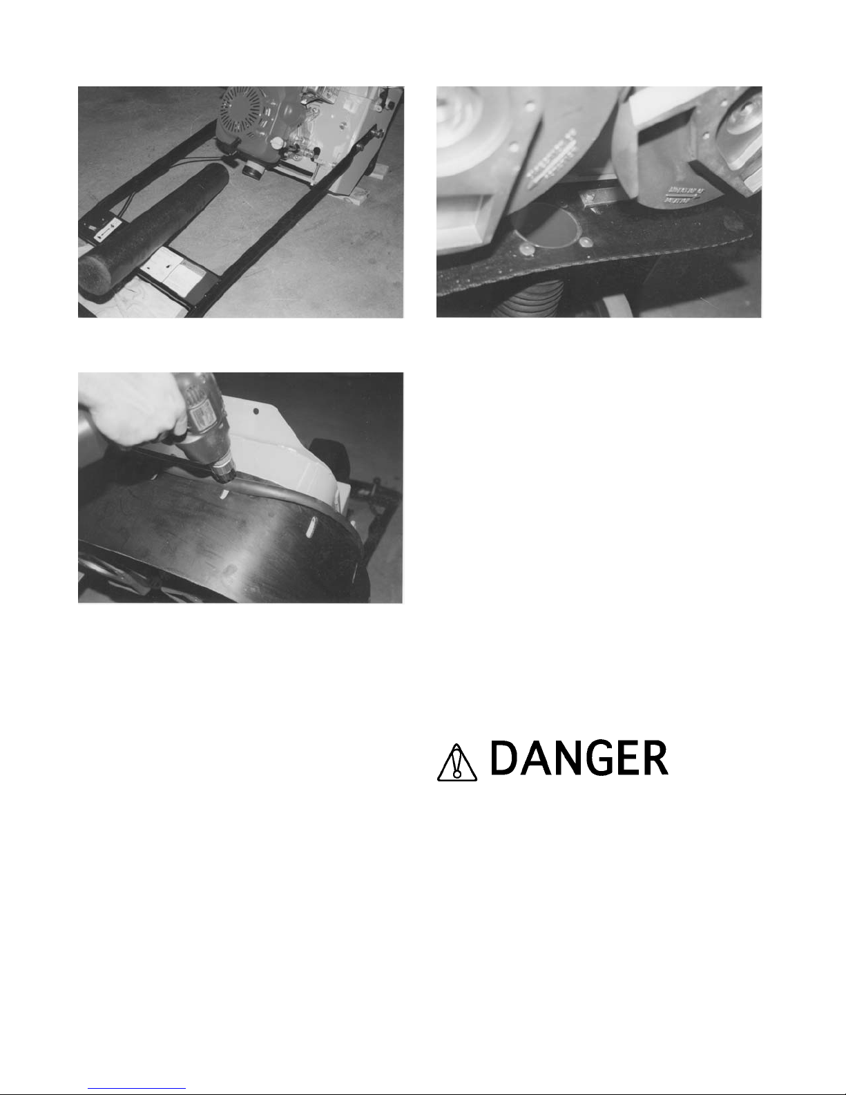
FIGURE 1
FIGURE 2
5) Using the 1/2 inch wrenches, the PN SG24-0350
rubber skirt is attached to the middle support member
of the main frame. Proper installation will have the
hose attach fitting that is riveted to the skirt facing the
rear of the machine. The notches in the rubber skirt
are provided as a means to compensate for multiaccessory attachment wear (if applicable). Adjust the
location of the rubber skirt to provide the same
clearance as with the PN SG24-0230 rubber skirt. The
PN SG24-0370 skirt straps provide additional support
for the rear skirt assembly. Properly secure with the PN
15050700 cap screws and PN 53050000 self locking
nuts, FIGURE 3.
FIGURE 3
6) Assemble the two each, PN 56480000 hose clamps
over the PN SG24-0380 vacuum hose. Install the
vacuum hose over the vacuum hose attach fittings.
Determine that the configuration minimizes potential
kinks or depressions which can reduce the airflow.
Secure the hose clamps tight with the screwdriver.
7) The PN SG24-1000 Safety and Dust Shield
Assembly Kit can be removed by reversing the above
procedure and reinstalling the original PN SG24-0220
bumper.
8) Return the Surface Grinder to its normal operating
position.
9) If the Surface Grinder is powered by an engine,
reconnect the engine spark plug wire. If powered by an
electric motor and the machine is to be used
immediately, reconnect the extension cord or Surface
Grinder to the power source. Determine that the
ON/OFF switch located on the operator handle is in the
OFF position.
UNEXPECTED MACHINE START UP CAN RESULT
IN PROPERTY DAMAGE AND/OR PERSONAL
INJURY.
SG24 GRINDER FORM GOM3259601, VERSION 1.2, AUTHORIZATION: DVR, PAGE: 13
Page 16

Before Starting the Engine
FILLING THE ENGINE CRANKCASE WITH OIL.
Applications: SG24/G Series and SG24/GHP
Surface Grinder
Note: The SG24/GHP Surface Grinder is shipped with
oil in the engine crankcase and with the Propane
cylinder empty. Units are test run to insure that the
Propane conversion components are functioning
properly. Regular gasoline powered units are selected
at random at the factory and also test run. These units
are shipped with oil in the engine crankcase. Fuel is
drained from the fuel tank and will be marked
accordingly by factory personnel.
Tools Required:
1 each, small, clean funnel
The SG24/G Series Surface Grinder is available
equipped with a variety of industrial quality, gasoline
and diesel engines. Engines are not normally
preserviced at the factory (see note above) and will
require the addition of oil in the crankcase before being
placed in service. Consult the material supplied by the
engine manufacturer for the engine that has been
ordered with your Surface Grinder. Carefully review
this material to become familiar with specific operating
characteristics, recommendations and service
requirements.
1) Determine the location(s) of both the oil filler and oil
drain plug(s).
2) Wipe oil, dust and accumulated dirt from the filler
plug area.
3) Using the funnel, fill the engine crankcase with a
high grade motor oil. Consult the material supplied by
the engine manufacturer for proper amount, weight
and service classification.
4) Replace the oil filler plug and tighten. Wipe off any
excess oil spilled on the engine crankcase and Surface
Grinder.
5) Do not operate the engine unless proper oil level is
maintained as per the material supplied by the engine
manufacturer.
FILLING THE SG24/G SERIES ENGINE FUEL TANK.
Tools Required:
1 each, small, clean funnel
NEVER MIX OIL WITH GASOLINE. FOUR CYCLE
ENGINES ARE NOT DESIGNED TO BE OPERATED
WITH OIL MIXED WITH THE GASOLINE.
1) Determine the location of the fuel tank filler cap.
2) Carefully clean the filler cap and surrounding area to
insure that no dirt or debris falls into the fuel tank.
Remove the filler cap.
3) Using the funnel, fill the fuel tank with fresh, clean
fuel according to the specifications outlined in the
material supplied by the engine manufacturer. Do not
overfill the tank or spill any fuel. If the fuel tank
incorporates a screen mesh to prevent debris from
falling into the tank, do not remove to increase the fill
rate. Replace the filler cap. Wipe away any excess
spilled fuel.
MANY FUELS ARE EXTREMELY FLAMMABLE. DO
NOT SMOKE NEAR THE FUEL TANK. DO NOT FILL
THE FUEL TANK WITH THE ENGINE RUNNING OR
IF IT IS HOT. ALLOW AMPLE TIME BETWEEN
EACH REFUELING FOR THE ENGINE TO COOL.
FILLING THE SG24/GHP PROPANE CYLINDER.
The SG24/GHP Surface Grinder is shipped from the
factory with a Propane conversion kit for the Honda
GXV340 engine and supplied with a standard 20 lb
capacity Propane cylinder. The Propane conversion is
performed by knowledgeable personnel licensed
and/or certified to perform the conversion. A copy of the
original licensing certificate is shipped with each
machine. If the original certificate becomes destroyed
or lost, contact the Customer Service Department for a
duplicate. There is no charge for this service.
Empty Propane cylinders should always be filled
according to established, industry standards by
SG24 GRINDER FORM GOM3259601, VERSION 1.2, AUTHORIZATION: DVR, PAGE: 14
Page 17

qualified personnel. Cylinders should be tested for
structural integrity according to industry standards
and/or local code requirements by qualified personnel
only.
IMPROPER USE, HANDLING AND MAINTENANCE
OF THE PROPANE CYLINDER CAN RESULT IN
PROPERTY DAMAGE AND/OR PERSONAL INJURY.
INSPECT THE CYLINDER, VALVE, FITTINGS,
HOSES AND HARDWARE FOR DAMAGE BEFORE
AND AFTER EACH USE. REPLACE ANY
QUESTIONABLE COMPONENT WITH A FACTORY
APPROVED REPLACEMENT ONLY. DO NOT
ALLOW ANY PERSONNEL TO OPERATE A
PROPANE CONVERTED ENGINE UNTIL PROPER
AND/OR ADEQUATE INSTRUCTION HAS BEEN
GIVEN WITH FULL COMPREHENSION.
PROPANE IS AN EXPLOSIVE GAS. DO NOT
SMOKE OR INTRODUCE AN OPEN FLAME IN OR
NEAR THE PROPANE CYLINDER AT ALL TIMES
WHEN FILLING, OPERATING/UTILIZING THE
SURFACE GRINDER OR PERFORMING ANY
MAINTENANCE.
Operation
THEORY OF OPERATION.
Application: All Models
The SG24 Series Surface Grinders operate on the
principle of various multi-accessory attachments being
utilized at rotational speeds to make direct contact with
a work surface. Various types of multi-accessory
attachments are secured to recesses provided in two,
counterrotating, aluminum discs located on the bottom
of the machine. The specific type of multi-accessory
attachment utilized during the grinding process directly
affects the type of material removed, the material
removal rate and the resulting flatness and
smoothness of the surface.
The grinding process is directly controlled by these
conditions:
1) The use of a suitable mechanism (multi-accessory
attachment) of proper design and configuration to grind
the work surface and remove material while delivering
acceptable service life.
2) Sufficient static weight supporting the multiaccessory attachment to allow it to effectively
penetrate the work surface and remove material.
3) Adequate horsepower capable of propelling the
multi-accessory attachment against the work surface
to deliver acceptable productivity rates.
Since no two materials are exactly alike, no two work
surface materials can be penetrated and removed by
the exact same method. The nature of the grinding
process, along with operator experience, skill and
common sense, would suggest that efficient and
productive material removal is a matter of trial and
error. Combinations of multi-accessory attachment
type, condition, and feed rate are direct factors that will
also determine the overall success of the job
application.
MULTI-ACCESSORY ATTACHMENTS AND
APPLICATIONS.
Application: All Models
While individual multi-accessory attachment design
and configuration may vary, basic operational
characteristics are identical: impact upon a work
surface material and remove a percentage of the
material. This common operational characteristic has
led to the development of the following popular multiaccessory attachments:
Grinding Stones
Grinding stones are available in a number of grades,
including: C06 extra coarse, C10 coarse, C24
medium, C80 fine and C120 super fine grade. All
stones incorporate silicon carbide as the abrasive
medium and employ a clay binder as the matrix
material. Vitrified type stones utilize an oven baking
process that produces greater service life over other
manufacturing processes. As the clay material wears
away, it exposes new, sharp, edges of the imbedded
silicon carbide material. All stones have the identical 2"
x 2" X 4" dimensions and are secured to the machine
by the use of a hardwood wedge, FIGURE 4.
SG24 GRINDER FORM GOM3259601, VERSION 1.2, AUTHORIZATION: DVR, PAGE: 15
Page 18

FIGURE 4
The designation system for the grinding stones utilizes
a system similarly utilized for most abrasive products:
the larger the number, the finer the grain structure and
usually, the smoother the resulting finish.
a) The C06 and C10 coarse grade stones are the most
popular utilized stones and result in maximum material
removal rates. They are utilized for general grinding
and the removal of trowel marks, high spots and rough
sections on concrete surfaces. The average service life
is approximately 4 to 10 hours.
b) The C24 medium grade stone will result in lower
material removal rates. It is utilized for finer finish
grinding of concrete and rough grinding on terrazzo
and other types of stone floor configurations. The
average service life is approximately 6 to 10 hours.
c) The C80 fine grade stone will result in still lower
material removal rates. It is utilized for polishing
concrete and medium grinding on terrazzo and other
types of stone floor configurations with a water/slurry
mixture only. The average service life is approximately
8 to 20 hours.
d) The C120 super fine grade stone will result in the
lowest material removal rates. It is utilized for final
polishing on terrazzo and other types of stone floor
configurations with a water/slurry mixture only. The
average service life is approximately 40 to 75 hours.
Tungsten Carbide Grinding Block
This multi-accessory attachment is most often utilized
on larger concrete grinding projects where increased
production and service life are required. The block
utilizes tungsten carbide balls approximately 1/16 inch
diameter that are deposited in a molten matrix material
during the manufacturing process at a controlled rate.
The end effect is a multi layer deposit of tungsten
carbide balls in the matrix material. As the softer matrix
material wears with use, it exposes a new layer of fresh
tungsten carbide balls to continue the grinding
process. The tungsten carbide grinding block is
considerably more aggressive than the C10 silicon
carbide grinding stone. With the ability to renew itself
during usage, the normal life expectancy for this
accessory can approach several hundred hours. The
nominal dimensions for the tungsten carbide grinding
block is 2" x 2" x 4" and is secured to the machine with
a hardwood wedge, FIGURE 5.
FIGURE 5
Scarifier Blocks
These multi-accessory attachments are comprised of
flails and spacer washers secured in a rigid steel case,
FIGURE 6. Rotation of the two multi-accessory discs
causes the flails to impact against the work surface
with a variety of results. Scarifier blocks are secured to
the machine with hardwood wedges.
Several factors directly affect the selection of a flail
design for a specific job application:
a) The type and amount of material to be removed from
the work surface. Materials of higher yield and tensile
strengths along with the actual volume of material to be
removed will generally be the first factors under
consideration.
b) Purchase cost versus service life. The original
purchase cost of plain, heat treated steel flails must be
compared against the substantially higher costs of the
tungsten carbide insert flails. In turn, these costs must
be compared to anticipated service life. All flails will
eventually wear to the point of requiring replacement.
SG24 GRINDER FORM GOM3259601, VERSION 1.2, AUTHORIZATION: DVR, PAGE: 16
Page 19

The amount of unproductive time spent to replace worn
flails on a job can be substantially greater than the
actual replacement cost of many flails. It then becomes
a balance between purchase cost, productivity, service
life and labor cost.
c) Surface finish and texture. The finest grained
surface finish available from the scarifying process is
comparable to a "swept or broomed" like finish. If a
smooth, flat finish is desired, the scarifying process
must be followed with a grinding or polishing type
process. Many job requirements may call for large
amounts of material to be removed, but followed with
additional specifications requiring a finer surface finish
or texture. Many times these jobs dictate the use of an
aggressive flail configuration because of productivity
and cost considerations. Less aggressive flail
configurations can then be utilized for the final finishing
sequence. Generally speaking, the more aggressive
the flail configurations, the more coarse the resulting
finish and texture.
Many flail configurations are available to meet a wide
variety of job applications and surface material
specifications. To give additional perspective to each
configuration, a rating system of 1 to 10 (10 being
highest) has been devised.
FIGURE 6
Star Flail
The star flail is manufactured from high carbon steel
that is thoroughly hardened for additional service life. It
is highly effective for light cleaning or scarifying and
delivers a finer surface finish texture, FIGURE 7.
Suggested applications:
1) Removal of thin coatings and encrusted
accumulations.
2) Cleaning concrete and asphalt surfaces.
3) Removing thick material build-ups of greases,
paints, oils, vegetable powders and some resins from
floors.
4) Light scarifying prior to the application of coatings,
toppings or sealers.
FIGURE 7
COST 1
PRODUCTIVITY 3
SERVICE LIFE 1
The star flail should be replaced when the outside
diameter is worn to approximately 1-5/16 inch or the
inside diameter elongates to approximately 3/4 inch.
Beam Flail
The beam type flail is manufactured from high carbon
steel that is thoroughly hardened for additional service
life. It is highly effective for scabbling or scarifying and
delivers medium to coarse surface finish texture,
FIGURE 8.
SG24 GRINDER FORM GOM3259601, VERSION 1.2, AUTHORIZATION: DVR, PAGE: 17
Page 20
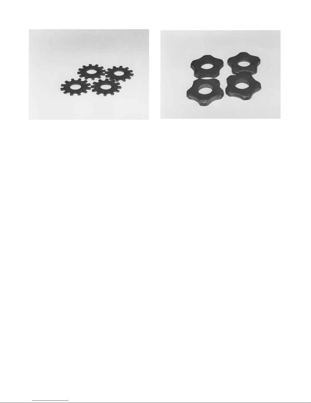
FIGURE 8
Suggested applications:
1) Medium duty asphalt and concrete scarifying.
2) Descaling steel decks.
3) Removing thick material build-ups of greases,
paints, oils, vegetable powders and some resins from
floors.
4) Dried, fully cured, carpet and tile adhesive removal.
COST 1
PRODUCTIVITY 5
SERVICE LIFE 2
The beam flail should be replaced when the outside
diameter is worn to approximately 1-5/16 inch or the
inside diameter elongates to approximately 3/4 inch.
Pentagonal Flail
The pentagonal type flail is manufactured from high
carbon steel that is throughly hardened for additional
service life. Each section of the five sided design
features a small, tungsten carbide insert that is held in
position with copper brazing. It is highly effective for
scabbling or scarifying and delivers medium to coarse
finish texture, FIGURE 9.
FIGURE 9
Suggested applications:
1) Heavy duty asphalt and concrete scarifying.
2) Heavy duty descaling of steel decks.
The pentagonal flail is designed for more aggressive
and rapid removal of a surface in comparison to the
beam flail. The addition of the tungsten carbide inserts
contributes to its long service life and higher production
rates. The use of tungsten carbide is also the main
reason for the cost differential between it and the other
flails. The design configuration yields a rather coarse
surface finish and texture. For many job applications,
this finish and texture will be satisfactory. Some
applications may require an additional smoothing
process. If the resulting surface finish is too coarse to
meet specifications, it can be smoothed with the use of
the star or beam flail.
COST 10
PRODUCTIVITY 8
SERVICE LIFE 10
The pentagonal flail should be replaced when two
successive tungsten carbide inserts break off or the
inside diameter elongates to approximately 3/4 inch. In
service, the flail body will wear much faster than the
tungsten carbide inserts. The copper brazing used to
weld the inserts into the body can fail and an insert
break off. The flail can still be used in service. It will just
wear a little faster and more uneven in that particular
area. As a general rule, a pentagonal flail can be
utilized until body wear will no longer support the
tungsten carbide inserts.
SG24 GRINDER FORM GOM3259601, VERSION 1.2, AUTHORIZATION: DVR, PAGE: 18
Page 21
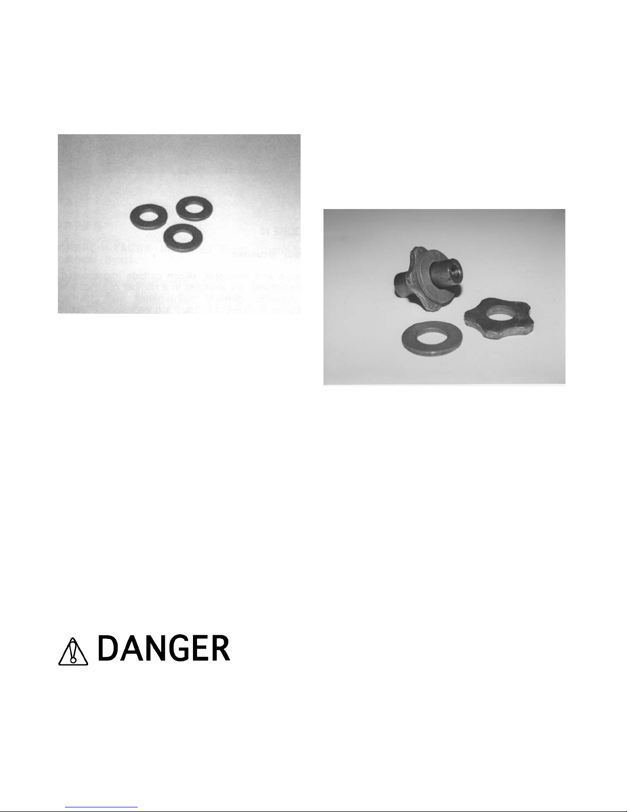
Spacer Washer
Spacer washers are stamped from high carbon steel
and heat treated for additional service life, FIGURE
10.
FIGURE 10
Spacer washers serve the following function:
1) Reduces the number of flails required to be mounted
on the scarifier block, thus reducing purchase and
operational costs.
2) Arrange the flails in a sequence or pattern that
minimize "blind" or "open" spots. Normally, at least one
spacer washer is inserted between two consecutive
flails. A scarifier block set up with only star, beam or
pentagonal flails will not penetrate the work surface at
satisfactory rates. This configuration will minimize the
hammering or impact action of the flails.
Variances in material thickness and manufacturing
processes can affect the final thickness of both flails
and spacer washers. Because of this occurrence, trial
and error is important for assembling flails and spacer
washer on the scarifier block. By mixing and matching
flails and spacer washers of specific thicknesses, the
required number of components can be assembled on
a block in a minimum amount of time.
USE ONLY FACTORY SUPPLIED SPACER
WASHERS ON THE SCARIFIER BLOCK. OTHER
WASHER TYPES AND/OR CONFIGURATIONS CAN
PRODUCE ABNORMAL WEAR AND ELONGATION,
RESULTING IN COMPLETE SEPARATION FROM
THE SCARIFIER BLOCK. INADVERTENT SPACER
WASHER SEPARATION CAN LEAD TO PROPERTY
DAMAGE AND/OR PERSONAL INJURY.
Scarifier Block Bushing
Scarifier block bushings are designed to be discarded
whenever the flails are replaced, FIGURE 11. Normal
wear should be uniform about the bushing
circumference.
FIGURE 11
Uneven bushing wear would suggest the following
problems:
1) Inadequate free play exists between the flails/spacer
washers and the scarifier block case. If the flails and
spacer washers do not have complete freedom of
movement, they will not be capable of properly rotating
about the scarifier block bushing. The result is bushing
wear usually confined to two locations that are 180
degrees apart. Variances in flail and spacer washer
thicknesses affect free play when assembled on the
scarifier block. Because free play is also created during
the scarifying process due to actual flail and spacer
washer wear, a certain amount of "tightness" can
sometimes be tolerated without affecting the service
life of the bushings and flails. The specific amount of
"tightness" can usually be determined through trial and
error. If the flails and spacer washers appear too tight
on the scarifier block, remove an appropriate flail or
washer and reassemble the block. If a short,
operational test indicates normal component wear
patterns, the apparent problem has been solved. A
general rule for consideration: it is better to have the
flails and spacer washers a "little too loose than a little
too tight".
SG24 GRINDER FORM GOM3259601, VERSION 1.2, AUTHORIZATION: DVR, PAGE: 19
Page 22
2) Mixing both worn and new flails on the scarifier
block. Proper flail action against the work surface
material requires that the flails be of the same
approximate dimensions. Flails with various inside and
outside dimensions will not impact the work surface
material with the same intensity and deliver the same
results. Flail bushing wear is directly proportional to the
amount of force it must supply against each individual
flail. When a bushing can no longer supply adequate
force against the flails, it will break, allowing the flails to
be hurdled against the inside of the Surface Grinder
frame. The more aggressive flails require greater
forces to keep them contained on the block. These
forces, in turn, create faster and/or uneven bushing
wear rates.
Because scarifier bushings are a critical component of
the actual scarifying process, it is important that each
bushing be inspected on a regular basis to determine
proper structural integrity.
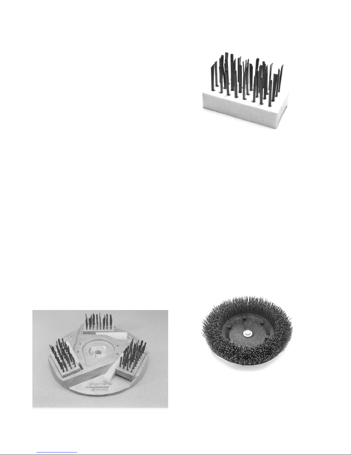
Wire Brushes
Typical applications include light scarifying and
cleaning of concrete, asphalt, steel and tile surfaces.
Wire brushes are secured to the machine with
hardwood wedges, FIGURE 12.
Wire brushes are available in a number of flat wire
sizes and resulting configurations. With continuous
use, the flat wire will take a "set" that can limit
effectiveness and overall productivity, FIGURE 13. For
best results, flat wire brushes should be rotated end for
end in the aluminum multi-accessory discs a minimum
of once for every one hour of operation. External
weight applied to the Surface Grinder will not normally
increase productivity rates and only accelerate flat wire
wear rates.
FIGURE 12
FIGURE 13
Floor Brushes
Eleven inch diameter, silicon carbide impregnated,
floor brushes are available in a number of styles and
designs for general maintenance and cleaning
projects, FIGURE 14. They are especially effective
cleaning soiled concrete floors with the addition of
water soluble solvents. These types of brushes are
directly mounted to the multi-accessory discs with the
included 1/2 inch x 2 inch long Grade 5 cap screws. A
kidney shaped drive plate is provided on the back side
of the brush. This drive plate fits into a recess provided
in the multi-accessory disc, FIGURE 15. To maximize
bristle service life, it is recommended that the silicon
impregnated brushes be rotated between multiaccessory discs a minimum of once for every one hour
of operation.
FIGURE 14
SG24 GRINDER FORM GOM3259601, VERSION 1.2, AUTHORIZATION: DVR, PAGE: 20
Page 23
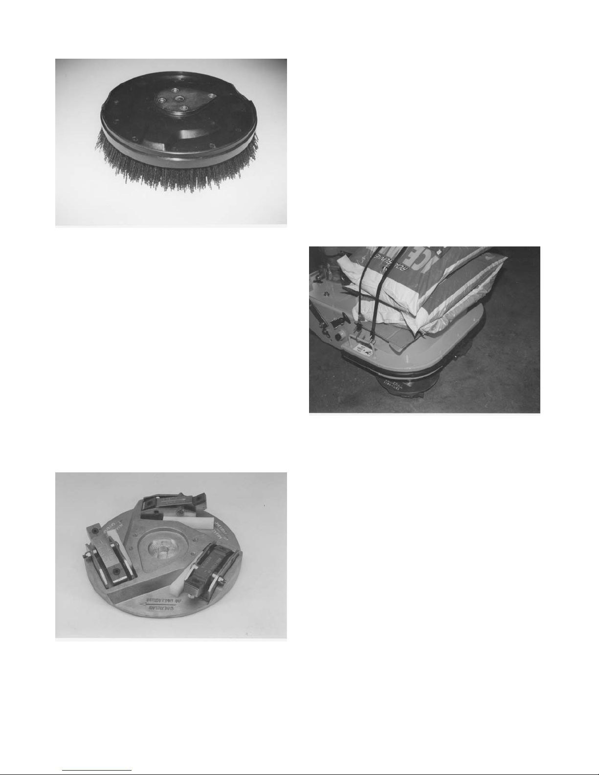
FIGURE 15
SCRAPE-R-TACH® Industrial Floor Coatings
Removal System
This multi-accessory attachment is designed to
remove many urethanes, epoxies, paints, mastics and
other, similar material accumulations from concrete
floor surfaces, FIGURE 16. Each assembly utilizes two
tungsten carbide inserts set at a precise angle. The
rotating inserts "cut and shave" against the work
surface material with a "scraping" action that removes
materials with highly productive results. To increase
the effectiveness of the inserts, the scraper block
design incorporates a Lord® type rubber mount that
helps absorb damaging shocks while allowing the
inserts to more easily follow local variations in the
surface contour. Units are secured to the machine with
hardwood wedges.
FIGURE 16
The productivity of the product is directly dependent
upon the yield and tensile strength of the material
being removed. Material thickness has also shown to
have a direct effect on overall productivity. For
example, the SCRAPE-R-TACH system is a highly
productive method for removing thick paint
accumulations from factory floors. Production rates of
up to several hundred square feet per hour can be
realized. However, many thin film ( ie: 5 mill thickness
and thinner) urethane coatings present a much more
difficult removal problem. Since removal rates are also
directly affected by applied down force, up to 300 lbs of
external weight can be added to the Surface Grinder to
increase productivity. Cement blocks or stacked bags
of cement make excellent weights and can be secured
with "bungy" cords or other means with the provided
holes in the top cover, FIGURE 17.
FIGURE 17
Each insert provides 8 scraping edges. As an edge
becomes dull and worn, the insert can be turned and
reinstalled to expose a new, sharp edge, FIGURE 18.
When all 4 edges of one side become worn and dull,
the insert can be turned over to expose an additional 4
edges.
Many materials such as adhesives, rubber deposits
and mastics have the tendency to extrude or smear
rather than shear from the concrete floor material. The
occurrence is also aggravated by higher ambient
temperatures. This problem can be significantly
reduced with the addition of various amounts of water
or a water saturated, fine sand combination placed on
the floor. The use of the Part Number SG24-1000
Safety and Dust Shield Assembly with the Surface
Grinder is highly recommended to contain the
water/sand slurry mixture from damaging surrounding
walls and other vertical surfaces, FIGURE 19.
SG24 GRINDER FORM GOM3259601, VERSION 1.2, AUTHORIZATION: DVR, PAGE: 21
Page 24
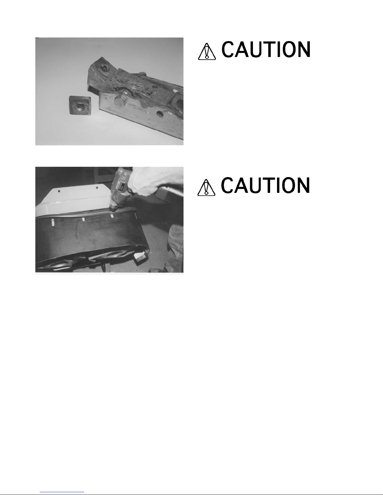
FIGURE 18
FIGURE 19
To index the tungsten carbide insert, proceed as
follows:
Tools required:
1 each, 5/32 Allen wrench
1 each, 7/16 inch wrench
1) Clean the SCRAPE-R-TACH unit with a suitable
safety solvent to remove excess material build-up.
Remove as much foreign material as possible from the
female hexagon socket area of the cap screw. This will
allow the wrench to make full contact and maximize the
torque transfer to the cap screw.
Follow all safety precautions for the safety solvent.
2) Remove the cap screw from the unit. Clean the
newly exposed areas of the insert and SCRAPE-RTACH unit with the safety solvent. Clean and inspect
the threaded holes found in older units for excess wear.
New style SCRAPE-R-TACH units feature a through
hole design.
3) Index the insert to expose a new edge. Reinstall the
cap screw (lock washer and hexagon nut on new style
units) and apply a torque value that properly seats the
insert firmly against the body of the unit.
An insufficient seating torque value will allow the
insert to become loose from the unit body,
resulting in premature component wear and
improper scraping action. An excessive torque
value will strip the threads of the cap screw or unit
body.
4) Determine that the unit body is free to rotate about
the 5/16 inch diameter cap screw that retains the body
to the unit. A body that does not freely rotate indicates
that a material build-up exists between the rubber
mount and retaining cap screw exits. This build-up
must be removed by disassembling the body from the
unit and cleaning all contact areas with the safety
solvent, FIGURE 20.
The SCRAPE-R-TACH system is designed to be
installed with the edge of the tungsten carbide inserts
facing the direction of rotation. Markings are provided
to indicate proper direction of rotation.
SG24 GRINDER FORM GOM3259601, VERSION 1.2, AUTHORIZATION: DVR, PAGE: 22
Page 25

FIGURE 20
Installing the SCRAPE-R-TACH system with the
tungsten carbide inserts facing opposite the
rotation direction will not deliver satisfactory
material removal rates and result in premature
component wear requiring early replacement.
Multi-Segmented, Dry Diamond Disc
Many times increased concrete removal rates can be
achieved with the use of multi-segmented, dry
diamond discs, FIGURE 21. These discs are designed
to operate dry or can also be utilized with water. If the
wet option is chosen, an external source for providing
water must be devised. No provision for water use is
provided with the Surface Grinder. Typical discs are
approximately 10 inches in diameter and feature up to
20 diamond segments that are welded or brazed to
each assembly.
To install the multi-segmented, dry diamond discs, the
standard, aluminum, multi-accessory discs are first
removed from the Surface Grinder. The diamond discs
fasten directly to the gimbal heads with 3/8 inch
diameter x 1 inch long Allen head cap screws, FIGURE
22. The rear wheel assembly is then placed in the
lowest position to compensate for the thickness
variance of the diamond disc, FIGURE 23.
FIGURE 21
To maximize the service life of the diamond segments,
its is recommended that the blades be rotated between
gimbal heads a minimum of once for every 8 hours of
operation.
FIGURE 22
Diamond Segment Block
The diamond insert block is designed to compliment
the multi-segmented diamond disc where a quick
changeover feature to other attachments is desired.
Diamond segments are retained into a steel block
assembly and deliver up to 5 times greater productivity
rates than the silicon carbide stones, FIGURE 24. The
design resists clogging while delivering a conservative
service life up to 15 times longer than the stones.
Diamond is the ideal choice for larger concrete removal
projects and the removal of epoxies, paints and many
thin film coatings.
SG24 GRINDER FORM GOM3259601, VERSION 1.2, AUTHORIZATION: DVR, PAGE: 23
Page 26
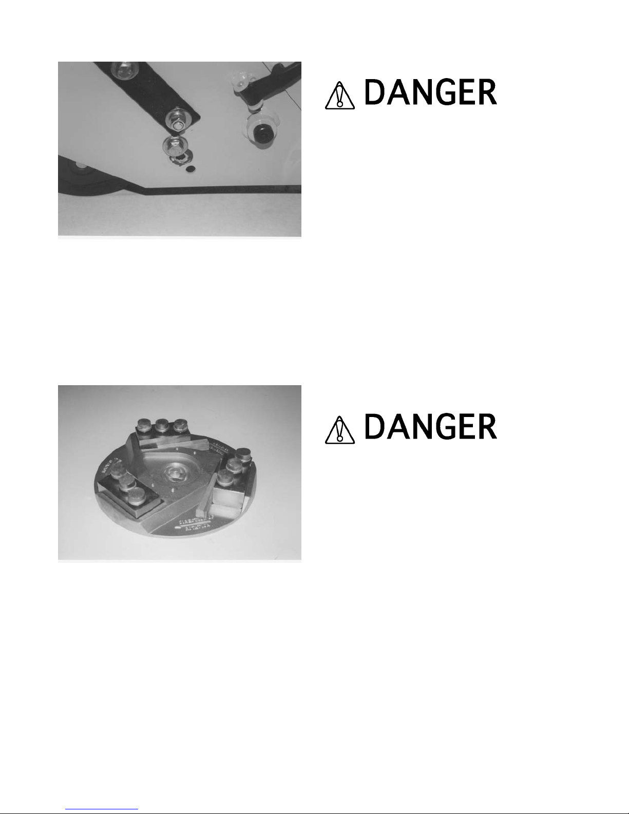
FIGURE 23
The concept is especially useful for removing a thin
layer of concrete in final preparation for a new coating
application. Can be used in both wet and dry job
applications. Worn inserts are easily replaced in a
matter of seconds. Service life is dependent upon
many variables, but can approach 35,000 square feet
per set, making it a cost efficient solution for many job
applications.
FIGURE 24
INSTALLING A MULTI-ACCESSORY ATTACHMENT
(not including multi-segmented, dry diamond
discs) IN THE COUNTERROTATING DISCS.
Application: All Models
Tools required:
1 each, small hammer
Parts required:
6 each, PN SG24-1800 Mounting Wedge
WHEN INSTALLING A MULTI-ACCESSORY
ATTACHMENT ON THE SURFACE GRINDER
ALWAYS WEAR THE APPROPRIATE SAFETY
EYEWEAR AND APPAREL TO MINIMIZE THE
POTENTIAL FROM FLYING DEBRIS. FLYING
DEBRIS CAN RESULT IN PROPERTY DAMAGE
AND/OR PERSONAL INJURY.
1) If the Surface Grinder is powered by an engine,
disconnect the spark plug wire. If powered by an
electric motor, properly disconnect the extension cord
or Surface Grinder from the power source
2) Tilt the Surface Grinder back until the operator
handle comes in contact with the surface. The Surface
Grinder may not be in a stable position in this
configuration. To minimize the possibility of property
damage and/or personal injury, properly secure an
appropriate weight to the handle for added stability.
Other means can also be utilized to support the frame
and provide proper machine stability. Appropriate
wheel chocks are also recommended, FIGURE 25.
EXERCISE EXTREME CAUTION WHEN WORKING
NEAR OR UNDER THE SURFACE GRINDER WITH
THE OPERATOR HANDLE TILTED BACK IN THE
SERVICE POSITION. IF THE SURFACE GRINDER IS
NOT POSITIONED IN A STABLE CONFIGURATION,
WITH ADEQUATE COUNTERWEIGHT PROPERLY
SECURED, UNEXPECTED MOVEMENT CAN
ALLOW THE SURFACE GRINDER TO FALL BACK
TO THE WORK SURFACE. THE RESULT CAN BE
PROPERTY DAMAGE AND/OR PERSONAL INJURY.
SG24 GRINDER FORM GOM3259601, VERSION 1.2, AUTHORIZATION: DVR, PAGE: 24
Page 27

FIGURE 25
3) Mount the multi-accessory attachment into the slots
provided in the multi-accessory discs. If the attachment
is directional in design, determine that its mounting
position in the disc allows for proper operation.
4) Force an SG24-1800 Mounting Wedge into the area
between the multi-accessory attachment and the
inside rib of the aluminum disc by hand. The straight
side of the mounting wedge contacts the multiaccessory attachment. The angled side of the
mounting wedge contacts the rib of the disc, FIGURE
26. An improper mounting configuration is depicted in
FIGURE 27.
FIGURE 26
FIGURE 27
DO NOT OPERATE THE SURFACE GRINDER WITH
THE SG24-1800 MOUNTING WEDGES IN AN
IMPROPER MOUNTING CONFIGURATION.
MOUNTING A WEDGE BETWEEN THE MULTIACCESSORY ATTACHMENT AND THE OUTSIDE
RIB OF THE ALUMINUM DISC CAN ALLOW THE
WEDGE TO COME IN DIRECT CONTACT WITH A
VERTICAL WALL AND/OR FLOOR OBSTRUCTION.
SUCH OCCURRENCE CAN RESULT IN LOSS OF
MACHINE CONTROL, PROPERTY DAMAGE
AND/OR PERSONAL INJURY.
BEFORE OPERATING THE SURFACE GRINDER
WITH ANY MULTI-ACCESSORY ATTACHMENT,
DETERMINE THAT NO PORTION OF THE
ATTACHMENT AND/OR MOUNTING WEDGE
EXTENDS BEYOND THE NORMAL PERIMETER OF
THE ALUMINUM DISC.
5) Using the hammer, strike the wider side of the
mounting wedge with controlled, direct blows to firmly
seat the multi-accessory attachment into the aluminum
disc. Usually one or two direct blows will be sufficient
to properly retain the attachment.
Do not apply excessive impact force to the
mounting wedge to cause splitting. Once the multiaccessory attachment is seated in the aluminum
disc, further impact force on the wedge will not
increase the seating force.
SG24 GRINDER FORM GOM3259601, VERSION 1.2, AUTHORIZATION: DVR, PAGE: 25
Page 28

Improper seating force created by an excessive
blow to the mounting wedge will not allow the
attachment to properly release from the aluminum
disc if direct contact with a foreign object is made.
Such occurrence can result in property damage
and/or personal injury. The correct seating force
for a specific job application is that which is
sufficient to retain the attachment, yet still allows it
to release from the aluminum disc when direct
contact with a foreign object is made.
6) Determine that the multi-accessory attachment is in
full contact with the aluminum disc. If not in proper
contact, refer to REMOVING A MULTI-ACCESSORY
ATTACHMENT (not including multi-segmented, dry
diamond blades) FROM THE COUNTERROTATING
DISCS for proper removal procedures.
7) Return the Surface Grinder to its normal operating
position.
8) If the Surface Grinder is powered by an engine,
reconnect the engine spark plug wire. If powered by an
electric motor and the machine is to be used
immediately, reconnect the extension cord or Surface
Grinder to the power source. Determine that the
ON/OFF switch located on the operator handle is in the
OFF position.
UNEXPECTED MACHINE START UP CAN RESULT
IN PROPERTY DAMAGE AND/OR PERSONAL
INJURY.
REMOVING A MULTI-ACCESSORY ATTACHMENT
(not including multi-segmented, dry diamond
discs) FROM THE COUNTERROTATING DISCS.
Application: All Models
Tools required:
1 each, small hammer
1 each, drift punch or small, pry bar
WHEN REMOVING A MULTI-ACCESSORY
ATTACHMENT FROM THE SURFACE GRINDER,
ALWAYS WEAR APPROPRIATE SAFETY
EYEWEAR AND APPAREL TO MINIMIZE THE
POTENTIAL FROM FLYING DEBRIS. FLYING
DEBRIS CAN RESULT IN PROPERTY DAMAGE
AND/OR PERSONAL INJURY.
1) If the Surface Grinder is powered by an engine,
disconnect the spark plug wire. If powered by an
electric motor, disconnect the extension cord or
Surface Grinder from the power source.
2) Tilt the Surface Grinder back until the operator
handle comes in contact with the surface. Follow the
instructions for this procedure as outlined in
INSTALLING A MULTI-ACCESSORY ATTACHMENT
(not including multi-segmented, dry diamond blades)
IN THE COUNTERROTATING DISCS.
3) The multi-accessory attachment can be removed by
both the use of a drift punch or small, pry bar. If utilizing
the drift punch, strike the narrow end of the mounting
wedge with controlled, direct blows until the
attachment is released from the aluminum disc. If
utilizing the pry bar, position the bar between the
aluminum disc and the attachment. Use controlled,
direct blows to the bar in order to force the attachment
loose from the aluminum disc, FIGURE 28.
FIGURE 28
SG24 GRINDER FORM GOM3259601, VERSION 1.2, AUTHORIZATION: DVR, PAGE: 26
Page 29

Do not utilize excessive force when removing a
multi-accessory attachment with the pry bar.
Excessive force can result in damage to the
aluminum disc. Proper removal techniques by both
methods will result in minimal damage to the
aluminum disc.
4) Return the Surface Grinder to its normal operating
position.
5) If the Surface Grinder is powered by an engine,
reconnect the spark plug wire. If powered by an electric
motor and the machine is to be used immediately,
reconnect the extension cord or Surface Grinder to the
power source. Determine that the ON/OFF switch
located on the operator handle is in the OFF position.
UNEXPECTED MACHINE START UP CAN RESULT
IN PROPERTY DAMAGE AND/OR PERSONAL
INJURY.
TRANSPORTING THE SURFACE GRINDER.
Application: All Models
The Surface Grinder has an operational weight that
prohibits one person from loading and/or unloading it
alone by conventional, physical efforts.
DO NOT ATTEMPT TO LIFT THE SURFACE
GRINDER UP INTO A TRANSPORTATION VEHICLE
WITH THE USE OF ONE PERSON ALONE. DO NOT
ATTEMPT TO LOWER THE SURFACE GRINDER
FROM A TRANSPORTATION VEHICLE WITH THE
USE OF ONE PERSON ALONE. LIFT AND/OR
LOWER THE SURFACE GRINDER ONLY BY THE
USE OF A POWER TAILGATE UNIT, A SUITABLE
HOIST UNIT OF PROPER CAPACITY AND/OR
CONFIGURATION OR BY THE USE OF A PROPER
QUANTITY OF PERSONNEL IN PROPER
PHYSICAL CONDITION.
1) A lifting bail device can be used to facilitate lifting by
a mechanical device incorporating a chain and suitable
attachment device. The location of the lifting bail may
not always locate the exact position of the center of
gravity for the Surface Grinder. Lifting handles are also
provided on both sides of the transmission case.
These handles can be utilized by personnel whenever
lifting/lowering the Surface Grinder or as attachment
points for a chain sling whenever a suitable hoisting
device is utilized, FIGURE 29.
EXERCISE EXTREME CAUTION WHEN UTILIZING
A MECHANICAL DEVICE FOR LIFTING THE
SURFACE GRINDER. UTILIZE THE MECHANICAL
DEVICE IN ACCORDANCE TO BOTH ITS STATED
STATIC AND DYNAMIC LOADING ENVELOPES. DO
NOT UTILIZE THE MECHANICAL DEVICE UNTIL
THIS INFORMATION IS PROPERLY KNOWN AND
UNDERSTOOD BY ALL APPLICABLE
PERSONNEL. FAILURE TO PROPERLY UTILIZE
THE MECHANICAL DEVICE CAN RESULT IN
PROPERTY DAMAGE AND/OR PERSONAL INJURY.
2) When transporting the Surface Grinder on a motor
vehicle, the fuel tank breather vent (if so equipped)
must be completely closed to eliminate the accidental
seepage of fuel and resulting potential fire and
environmental hazards. If the engine is Propane
converted, the cylinder should be removed from the
Surface Grinder and all valves, hoses, fittings and
related hardware be inspected for proper security and
leaks. Transport the Propane cylinder in accordance to
all local, State and Federal regulations. Properly
secure and store the Propane cylinder to minimize the
possibility of property damage and/or personal injury.
3) To minimize the possibility of damage to the Surface
Grinder, always transport in its normal, upright position.
All equipment must be secured in/on vehicles with
suitable strapping or tie-downs. Personnel should not
be transported in the same compartment as equipment
and fuel supplies. Consult applicable OSHA, AGA,
CGA, etc. regulations for the proper transportation of
Propane and other, flammable gases.
ADJUSTING THE OPERATOR HANDLE HEIGHT.
Application: All Models
The SG24 Series Surface Grinder incorporates a
handle that can be adjusted to compensate for
variances in operator heights. Three adjustment
SG24 GRINDER FORM GOM3259601, VERSION 1.2, AUTHORIZATION: DVR, PAGE: 27
Page 30

heights are provided. Correct handle height can
increase overall machine productivity and reduce
operator fatigue.
FIGURE 29
Tools Required:
1 each, 3/4 wrench or suitable alternative.
1) Using the wrench, loosen the 1/2 inch hexagon nuts
from the stud assemblies that retain the handle to the
main frame.
2) Using the wrench, remove the 1/2 inch cap screws
that retain the handle in position on the main frame.
EXERCISE EXTREME CAUTION WHEN REMOVING
THE RETAINING CAP SCREWS FROM THE MAIN
FRAME. WHEN THE FINAL CAP SCREW IS
REMOVED, THE HANDLE IS PROVIDED WITH NO
EXTERNAL SUPPORT AND WILL IMMEDIATELY
DROP TO THE FLOOR. SUCH OCCURRENCE CAN
RESULT IN PROPERTY DAMAGE AND/OR
PERSONAL INJURY.
3) Reposition the operator handle in the desired
location that aligns the hole in the handle with the
threaded hole in the main frame. Replace the 1/2 inch
hexagon cap screws and properly tighten with the
wrench, FIGURE 30.
4) Using the wrench, properly tighten the 1/2 inch
hexagon nuts on the stud assemblies that retain the
handle to the main frame.
FIGURE 30
STARTING THE SG24/E SERIES ELECTRICALLY
POWERED SURFACE GRINDER ON THE JOB SITE.
1) Position the Surface Grinder on a flat and level
surface of firm foundation.
2) Determine that the ON/OFF switch located on the
operator handle is in the OFF position.
UNEXPECTED MACHINE START UP CAN RESULT
IN PROPERTY DAMAGE AND/OR PERSONAL
INJURY.
3) Select the appropriate operating voltage for the
electric motor. The motor is designed to operate from
a clean, 20 ampere, 115 VAC, 60 Hz nominal or a
clean, 10 ampere, 230 VAC, 60 Hz nominal power
source. A clean power source refers to the amperage
available on the individual electrical circuit selected.
Additional electrical products already utilizing the same
circuit will reduce the available amperage, resulting in
starting and operational difficulties.
A voltage switch (115/230 VAC, 60 Hz) is provided on
the motor. For added security, the voltage switch can
be locked in position with a combination or keyed lock
with an extended shank length, FIGURE 31.
SG24 GRINDER FORM GOM3259601, VERSION 1.2, AUTHORIZATION: DVR, PAGE: 28
Page 31

Operating the Surface Grinder from a power
source of improper voltage and amperage will
result in unrepairable damage to the electric motor
and related controls.
FIGURE 31
4) Providing proper voltage and amperage levels to the
electric motor is essential to obtain maximum
productivity and service life. Low voltage and
amperage levels will cause the motor to overheat. The
motor is equipped with automatic thermal protection
device that will stop it before major internal damage
can result. After the motor has cooled to an acceptable
temperature level, the switch must be manually
activated to restart, FIGURE 32.
To minimize the voltage drop to the motor, all extension
cords should be copper stranded, 8 AWG or larger. A
NEMA 6-20R twist lock type receptacle is provided with
the SG24/E Series Surface Grinder as a standard
accessory. The twist lock feature allows the extension
cord to be pulled by the Surface Grinder without
becoming detached. Wire the NEMA 6-20R receptacle
to the appropriate extension cord that will be coupled
to the NEMA 6-20P plug provided on the Surface
Grinder, FIGURE 33.
FIGURE 32
FIGURE 33
PROPERLY INSPECT ALL EXTENSION CORDS
AND WIRING DEVICES FOR STRUCTURAL
INTEGRITY. DO NOT UTILIZE A CORD WITH A
WORN OR CUT OUTER JACKET MATERIAL. DO
NOT UTILIZE A CORD WITH EXPOSED INNER
WIRES OR INSULATION MATERIAL. DO NOT
UTILIZE A CORD THAT HAS BEEN REPAIRED
WITH ELECTRICAL TAPE. USE OF AN EXTENSION
CORD OF IMPROPER STRUCTURAL INTEGRITY
CAN RESULT IN PROPERTY DAMAGE AND/OR
PERSONAL INJURY.
SG24 GRINDER FORM GOM3259601, VERSION 1.2, AUTHORIZATION: DVR, PAGE: 29
Page 32

ALL ELECTRICAL WIRING MUST BE INSTALLED
AND/OR APPROVED IN ACCORDANCE TO LOCAL
ELECTRICAL CODES AND PRACTICES. AN
IMPROPER WIRING INSTALLATION CAN RESULT
IN PROPERTY DAMAGE AND/OR PERSONAL
INJURY.
5) Determine that the power outlet to be utilized is
properly grounded. This can be accomplished with
proper testing equipment and procedures. If there are
any questions regarding the suitability of a specific
power outlet, contact the Customer Service
Department for assistance BEFORE utilizing the
Surface Grinder. There is no charge for this service. A
qualified electrician can also be consulted. If a 115
VAC power outlet is selected, it is recommended that a
properly tested, externally mounted, ground fault circuit
interrupter (GFCI) be utilized at all times as an
additional safety precaution. Ground fault circuit
interrupters are not available for operation on 230 VAC,
FIGURE 34.
FIGURE 34
FOR MAXIMUM PROTECTION AGAINST A FAULT,
ALWAYS CONFIGURE THE GROUND FAULT
CIRCUIT INTERRUPTER TO BE PLUGGED INTO
THE EXTENSION CORD. A CONFIGURATION WITH
THE GROUND FAULT CIRCUIT INTERRUPTER
PLACED BETWEEN THE POWER SOURCE AND
THE EXTENSION CORD WILL NOT AFFORD
MAXIMUM PROTECTION AGAINST A POTENTIAL
FAULT.
6) Couple the NEMA 6-20R receptacle and the NEMA
6-20P plug together.
7) Grasp the operator handle with firm gripping. When
starting the electric motor, apply a down force directly
to the operator handle to help reduce the amount of
machine weight against the work surface. Turn the
ON/OFF switch to the ON position. Reduce the amount
of applied down force on the operator handle as the
electric motor attains its operational speed.
When operating on 115 VAC, the electric motor will
require additional starting time to help compensate for
the additional starting amperage requirement. This
time is usually within two seconds of activating the
ON/OFF switch.
8) The SG24/E Series electrically powered Surface
Grinder is not equipped with a centrifugal clutch
assembly. The electric motor is directly coupled to the
multi-accessory discs by a V-belt/spur gear
transmission.
AS SOON AS THE ELECTRIC MOTOR HAS
STARTED, THE OPERATOR MUST BE IN A
POSITION TO ASSUME DIRECT AND FULL
CONTROL OF THE SURFACE GRINDER. FAILURE
TO ASSUME DIRECT AND FULL CONTROL CAN
RESULT IN PROPERTY DAMAGE AND/OR
PERSONAL INJURY.
9) The SG24/E Series electrically powered Surface
Grinder is stopped by moving the ON/OFF switch
located on the operator handle to the OFF position. For
safety considerations, it is also recommended that the
extension cord be disconnected from both the Surface
Grinder and electric power source whenever the
Surface Grinder is not in use on the job site.
STARTING THE SG24/G SERIES GASOLINE
POWERED SURFACE GRINDER ON THE JOB SITE.
1) Position the Surface Grinder on a flat and level
surface of firm foundation.
2) Refer to the material supplied by the engine
manufacturer for the correct starting, operation and
stopping procedures.
SG24 GRINDER FORM GOM3259601, VERSION 1.2, AUTHORIZATION: DVR, PAGE: 30
Page 33

3) The SG24/G Series Surface Grinder is equipped
with a centrifugal clutch assembly. The clutch is
designed to engage at approximately 2400 RPM
engine speed. Normal operation of the clutch will allow
the engine to operate at its designated idle speed
without the multi-accessory discs rotating. If the multiaccessory discs rotate below the designated engine
idle speed, do not continue to operate the Surface
Grinder until the problem has been properly corrected.
Consult the Customer Service Department for specific
information. There is no charge for this service.
AS SOON AS THE CENTRIFUGAL CLUTCH
ASSEMBLY BECOMES ENGAGED, THE
OPERATOR MUST BE IN A POSITION TO ASSUME
DIRECT AND FULL CONTROL OF THE SURFACE
GRINDER. FAILURE TO ASSUME DIRECT AND
FULL CONTROL CAN RESULT IN PROPERTY
DAMAGE AND/OR PERSONAL INJURY.
DO NOT OPERATE A GASOLINE ENGINE IN
CLOSED SPACES WITHOUT PROPER
VENTILATION. GASOLINE ENGINES PRODUCE
CARBON MONOXIDE FUMES. BREATHING
CARBON MONOXIDE FUMES CAN RESULT IN
PROPERTY DAMAGE AND/OR PERSONAL INJURY.
EXCESSIVE LEVELS OF CARBON MONOXIDE CAN
CAUSE DEATH.
4) Stop the engine in accordance with the instructions
as described in the material supplied by the engine
manufacturer.
PROCEDURES FOR THE SAFE HANDLING OF
PROPANE.
PROPANE IS AN EXPLOSIVE GAS THAT CAN
RESULT IN PROPERTY DAMAGE AND/OR
PERSONAL INJURY IF IMPROPERLY
TRANSPORTED, HANDLED AND UTILIZED. DO
NOT SMOKE OR INTRODUCE AN OPEN FLAME IN
THE VICINITY OF A PROPANE CYLINDER OR THE
SURFACE GRINDER AT ANY TIME. CONSULT
APPLICABLE DEPARTMENT OF
TRANSPORTATION AND OSHA REGULATIONS
PERTAINING TO THE USE OF PROPANE AND
PROPANE CONVERTED EQUIPMENT.
1) PERFORM ALL SERVICE WORK ON THE
SURFACE GRINDER IN AN OPEN OR WELL
VENTILATED AREA. NEVER ALLOW PROPANE
GAS TO ESCAPE IN A CLOSED AREA. PROPANE
IS HEAVIER THAN STANDARD AIR AND MAY
SETTLE IN LOW AREAS.
2) NEVER PERFORM ANY CUTTING, WELDING OR
REPAIR PROCESS THAT INTRODUCES AN OPEN
FLAME AND/OR SPARKS IN THE VICINITY OF THE
PROPANE CONVERSION SYSTEM.
3) HANDLE THE PROPANE CYLINDER
CAREFULLY. DO NOT DRAG OR DROP THE
CYLINDER. SUCH ACTION CAN RESULT IN
PROPERTY DAMAGE AND/OR PERSONAL INJURY.
4) INSTALLATION, MAINTENANCE AND REPAIR
WORK SHOULD BE ACCOMPLISHED BY
QUALIFIED SERVICE PERSONNEL.
5) NEVER TEST FOR SYSTEM LEAKS WITH AN
OPEN FLAME. ALWAYS USE SOAP SUDS OR AN
APPROVED LEAK DETECTOR.
6) DO NOT FILL A CYLINDER THAT IS NOT
PROPERLY LABELED FOR USE WITH PROPANE.
7) DO NOT FILL A CYLINDER THAT DOES NOT
HAVE A CURRENT AND/OR VALID HYDROTEST
DATE PROPERLY STAMPED ON ITS SURFACE.
EXAMPLE OF A PROPANE EMERGENCY PLAN.
Operators of the SG24/GHP Surface Grinder are
advised to design and implement a Propane
emergency plan in the event that the Propane cylinder,
hoses, connections or engine conversion components
develop leaks which allow the Propane to escape into
the atmosphere. Propane is an extremely flammable
gas that can cause property damage and personal
injury.
SG24 GRINDER FORM GOM3259601, VERSION 1.2, AUTHORIZATION: DVR, PAGE: 31
Page 34

THE FOLLOWING INFORMATION IS INTENDED TO
PROVIDE A BASIS FOR A PLAN AND IS NOT
INTENDED TO BE ALL INCLUSIVE. THE KEY
WORDS WILL BE ARRANGED TO SPELL OUT THE
WORD PROPANE.
1) PROPANE EMERGENCY. Instruct all personnel to
shout out the warning PROPANE EMERGENCY,
followed by the location. Example: Propane
emergency, warehouse 2.
2) REPEAT THE CALL. Upon hearing the warning,
each personnel should repeat the warning.
3) OFF WITH ALL UTILITIES. Personnel nearest the
utilities should pull all main switches and close all
related valves.
4) PHONE THE FIRE DEPARTMENT. Give the
location, specific details of the emergency and
directions to the location site. Do not hang up until the
fire department has the complete information it
requires. Carbon dioxide and dry chemical fire
extinguishers may be used. NEVER UTILIZE
CARBON TETRACHLORIDE FIRE
EXTINGUISHERS.
5) ALL TOOLS OFF. Immediately turn off all air,
hydraulic and electrically powered tools and machines.
6) NO VEHICLES MOVE. No vehicles, even if
electrically powered are allowed to operate. Shut down
all vehicle accessories, including two-way radios.
7) EVACUATE NOW. Have all personnel walk to the
nearest exit away from the direction of the emergency
area.
STARTING THE SG24/GHP PROPANE CONVERTED
SURFACE GRINDER ON THE JOB SITE.
1) Position the Surface Grinder on a flat and level
surface of firm foundation.
2) Inspect the Propane cylinder, all hoses, fittings and
conversion components for visible damage and the
potential for leaks. Leaks can be detected by applying
a soap and water mixture to connections with a non
metallic (spark proof) brush.
USE OF A METALLIC AND/OR IMPROPER TYPE
BRUSH CAN PRODUCE SPARKS. SUCH
OCCURRENCE CAN BE THE IGNITION SOURCE
OF AN EXPLOSION, RESULTING IN PROPERTY
DAMAGE AND/OR PERSONAL INJURY.
3) Determine that the Propane cylinder is properly
fastened and secured in the mounting cradle.
AN IMPROPERLY SECURED PROPANE CYLINDER
CAN BE THE CAUSE OF DAMAGED/LEAKING
FITTINGS, HOSE AND OTHER COMPONENTS,
RESULTING IN PROPERTY DAMAGE AND/OR
PERSONAL INJURY.
4) Open the Propane cylinder valve.
5) Move the engine throttle control lever to the 1/4
open position.
6) Propane converted, gasoline engines do not require
the addition of choke for the starting procedure. An
engine choke control mechanism is not provided on the
converted engine.
7) Depress both the regulator and filter buttons for one
second, FIGURE 35.
8) Start the engine by pulling on the recoil starter
handle. The engine will normally start within 1 or 2
pulls. If the engine fails to start, repeat Steps 7 and 8
until starting is accomplished.
9) The SG24/GHP Propane converted Surface Grinder
is equipped with a centrifugal clutch assembly. The
clutch is designed to engage at approximately 2400
RPM engine speed. Normal operation of the clutch will
allow the engine to operate at its designated idle speed
without the multi-accessory discs rotating. If the multiaccessory discs will not stop rotating at the lowest
engine idle speed, do not continue to operate the
Surface Grinder. Contact the Customer Service
Department for specific information. There is no charge
for this service.
SG24 GRINDER FORM GOM3259601, VERSION 1.2, AUTHORIZATION: DVR, PAGE: 32
Page 35

FIGURE 35
AS SOON AS THE CENTRIFUGAL CLUTCH
ASSEMBLY BECOMES ENGAGED, THE
OPERATOR MUST BE IN A POSITION TO ASSUME
DIRECT AND FULL CONTROL OF THE SURFACE
GRINDER. FAILURE TO PROPERLY ASSUME
DIRECT AND FULL CONTROL CAN RESULT IN
PROPERTY DAMAGE AND/OR PERSONAL INJURY.
DO NOT OPERATE A GASOLINE ENGINE IN
CLOSED SPACES WITHOUT PROPER
VENTILATION. GASOLINE ENGINES PRODUCE
CARBON MONOXIDE FUMES. BREATHING
CARBON MONOXIDE FUMES CAN RESULT IN
PROPERTY DAMAGE AND/OR PERSONAL INJURY.
EXCESSIVE LEVELS OF CARBON MONOXIDE CAN
CAUSE DEATH.
10) The SG24/GHP Surface Grinder is stopped by
moving the engine throttle control lever to the STOP
position.
11) Close the Propane cylinder valve.
12) Inspect the Propane cylinder, all hoses, fittings and
conversion components for visible damage during use
and the potential for leaks. Replace any questionable
component with a factory approved replacement only.
If the Surface Grinder and/or an individual
component/accessory does not appear to be
functioning properly, STOP and do not further
operate the Surface Grinder until the proper
corrective action has been completed. If there are
any questions regarding the proper operation of
the Surface Grinder, contact the Customer Service
Department BEFORE further utilization. There is no
charge for this service.
COUNTERACTING THE PROPANE
REFRIGERATION EFFECT.
The combination of a high Propane flow rate and
relatively small cylinder size (20 lbs.) can produce a
sudden and drastic reduction in heat output and/or
engine stoppage even though a substantial quantity of
Propane remains in the cylinder.
Propane in the cylinder is in a liquid state. It must be
vaporized before it can be utilized in the internal
combustion process. But vaporization requires the
absorption of heat energy and the source of this energy
has an important bearing upon the operation of the
Surface Grinder.
Since the Propane is enclosed inside the cylinder, the
pressure rises. It rises until it reaches a limit for that
temperature. This local pressure, referred to as the
vapor pressure, is what delivers the Propane vapor to
the engine. Vapor pressure is a variable entity. It
decreases as ambient temperature decreases and
increases as ambient temperature increases. If the
temperature of the Propane becomes too low,
insufficient pressure will be available to operate the
Surface Grinder. This can especially happen if the
Surface Grinder is operated in very cold climates.
The problem is that Propane actually cools itself. There
are two factors that can affect Propane temperature.
The first factor is ambient, or the surrounding air
temperature. The second factor has to do with the
absorption of heat energy when liquid Propane
vaporizes. As the Propane inside the cylinder begins to
vaporize it actually robs or reduces the temperature of
the Propane that remains. Each pound of Propane
requires 185 BTU just to change states from a liquid to
a vapor. The effect is to cool the remaining Propane.
SG24 GRINDER FORM GOM3259601, VERSION 1.2, AUTHORIZATION: DVR, PAGE: 33
Page 36

The cooling process is known as the refrigeration
effect. If it continues long enough and proceeds fast
enough, the Propane temperature and pressure will fall
so low that continued operation of the Surface Grinder
can be impossible, even with a full cylinder. Frost often
forms on the outside of the cylinder as a warning that
excessive refrigeration is occurring.
Fortunately, the refrigeration effect can be
counterbalanced by a flow of heat energy into the
cylinder from warmer, ambient air. This occurrence is
referred to as convection heating. It can replace much
of the heat energy lost in the course of vaporizing the
Propane, thus effectively slowing the cooling process.
In many cases, convection heating works well enough
to effectively counterbalance the refrigeration effect,
but there are still a number of external factors that can
reduce efficient convection.
The first factor is that the surface area of liquid
Propane inside the cylinder decreases with usage. A
decreasing amount of liquid surface area available for
convection heating produces an increase in the
refrigeration effect and increased Propane cooling.
Let's take the example of a filled cylinder. At first, the
Propane temperature drops rapidly as the vaporizing
Propane robs the heat energy of the remaining liquid
supply. However, the colder Propane causes heat to
flow into the cylinder from the warmer, ambient air. The
process remains almost steady state until the heat
transfer area (dictated by the amount of liquid Propane
inside the cylinder) is substantially reduced. At that
time, the heat inflow is reduced and accelerates the
cooling process of the Propane until the vaporization
rate can no longer be maintained.
Another factor that aggravates the refrigeration effect
is increasing the flow rate. Operating the engine at a
higher speed requires a higher fuel flow rate. Propane
cooling is in directly proportional to the vaporization
rate. Many times this rate can not be counteracted by
convection heating. The process drastically reduces
the amount of fuel made available to the engine.
Frost accumulation on the cylinder can also impede the
efficiency of heating convection. Use of the Surface
Grinder in high humidity areas can also create the
formation of frost on the cylinder. The high water vapor
content of humid air comes in direct contact with the
colder exterior surface of the cylinder and locally
freezes. Frost creates an insulation blanket
surrounding the cylinder that effectively prevents heat
energy transfer or convection heating necessary to
counterbalance the refrigeration effect.
While frost is an enemy, wind actually is an ally. Direct
exposure to forced convection in the form of wind
flowing over the cylinder creates a boundary layer. The
boundary layer substantially increases the amount of
convection heating.
There are several other tips that can be demonstrated
to reduce refrigeration effect.
a) Keep the cylinder filled, especially in cold weather.
Never allow the Propane level to fall below 1/3 of its
rated capacity.
b) Whenever possible, always store cylinders in a
warm storage area.
c) The Propane conversion kit includes a vaporizer to
assist proper flow rates during operation in cold,
ambient temperatures.
d) Watch for and avoid the formation of frost on the
cylinder. Keep the cylinder fully exposed to the
surrounding ambient air. Do not cover or protect the
cylinder so as to become obstructed.
e) Whenever possible, keep the cylinder exposed into
the prevailing wind. This will significantly increase the
heat transfer rate and overall utilization time from the
cylinder.
OPERATING THE SURFACE GRINDER ON THE
JOB SITE.
Application: All Models
THE GRINDING PROCESS PRODUCES
EXCESSIVE NOISE, VIBRATION AND FLYING
DEBRIS. ALL OPERATORS AND WORK
PERSONNEL IN THE VICINITY OF THE SURFACE
GRINDER MUST WEAR APPROPRIATE SAFETY
EYE WEAR AND HEARING PROTECTION
DEVICES. OTHER SAFETY APPAREL AND/OR
PROCEDURES, DEEMED NECESSARY BY
SUPERVISORY PERSONNEL MUST ALSO BE
WORN AND/OR PRACTICED BY ALL
APPROPRIATE PERSONNEL.
SG24 GRINDER FORM GOM3259601, VERSION 1.2, AUTHORIZATION: DVR, PAGE: 34
Page 37

EXERCISE EXTREME CAUTION WHEN
OPERATING THE SURFACE GRINDER IN THE
VICINITY OF DECK INSERTS, PIPES, COLUMNS,
OPENINGS, LARGE CRACKS, UTILITY OUTLETS
OR ANY OBJECT PROTRUDING FROM THE
SURFACE. CONTACT WITH SUCH OBJECTS CAN
LEAD TO LOSS OF MACHINE CONTROL,
RESULTING IN PROPERTY DAMAGE AND/OR
PERSONAL INJURY.
DO NOT OPERATE A GASOLINE ENGINE IN
CLOSED SPACES WITHOUT PROPER
VENTILATION. GASOLINE ENGINES PRODUCE
CARBON MONOXIDE FUMES. BREATHING
CARBON MONOXIDE FUMES CAN RESULT IN
PROPERTY DAMAGE AND/OR PERSONAL INJURY.
EXCESSIVE LEVELS OF CARBON MONOXIDE CAN
CAUSE DEATH
1) The Surface Grinder incorporates counterrotating
discs for mounting a wide variety of multi-accessory
attachments. The counterrotating action results in a
"self propelled" effect that substantially enhances
machine control and reduces fatigue as long as the
multi-accessory attachment does not come in direct
contact with a protruding obstruction from the floor.
Direct contact with such an obstruction can result in
rapid and jerky directional movement of the machine.
In most operating situations, direct contact with a
protruding obstruction from the floor will result in the
multi-accessory attachment becoming dislodged from
the counterrotating disc. This occurrence is intended to
protect the Surface Grinder from excessive damage
and allow the operator to remain in proper control of
the machine.
ALWAYS MAINTAIN PROPER CONTROL OF THE
SURFACE GRINDER. IF AN OPERATOR LOOSES
CONTROL OF THE MACHINE, A "RUNAWAY"
SURFACE GRINDER CAN RESULT IN PROPERTY
DAMAGE AND/OR PERSONAL INJURY. BECAUSE
OF THE UNIQUE OPERATING CHARACTERISTICS
OF THE SURFACE GRINDER, THERE IS NO
PROVISION FOR THE ELECTRIC MOTOR/ENGINE
TO AUTOMATICALLY STOP IF THE OPERATOR
FAILS TO MAINTAIN PROPER CONTROL.
WHEN OPERATING THE SURFACE GRINDER ON
ABOVE GROUND FLOOR LEVELS, EXERCISE
EXTREME CAUTION TO PREVENT LOSS OF
CONTROL THAT COULD ALLOW THE MACHINE
AND/OR OPERATOR TO FALL DOWN TO LOWER
LEVELS. SUCH AN OCCURRENCE CAN RESULT IN
PROPERTY DAMAGE AND/OR PERSONAL INJURY.
2) Productivity rates with the various multi-accessory
attachments can be increased with the addition of
external weight being applied to the area over the
counterrotating discs, FIGURE 36. Maximum allowable
external weight is 300 lbs. Exceeding this figure can
result in permanent structural damage to the Surface
Grinder. Provisions for securing the weight by the
means of strapping or other, appropriate methods is
provided.
FIGURE 36
DO NOT OPERATE THE SURFACE GRINDER
WITHOUT ALL EXTERNAL WEIGHT PROPERLY
SECURED TO THE MAIN FRAME. A SUDDEN
CHANGE IN MOVEMENT OR DIRECTION CAN
ALLOW THE UNSECURED WEIGHT TO FALL OFF
THE SURFACE GRINDER, RESULTING IN LOSS OF
SG24 GRINDER FORM GOM3259601, VERSION 1.2, AUTHORIZATION: DVR, PAGE: 35
Page 38
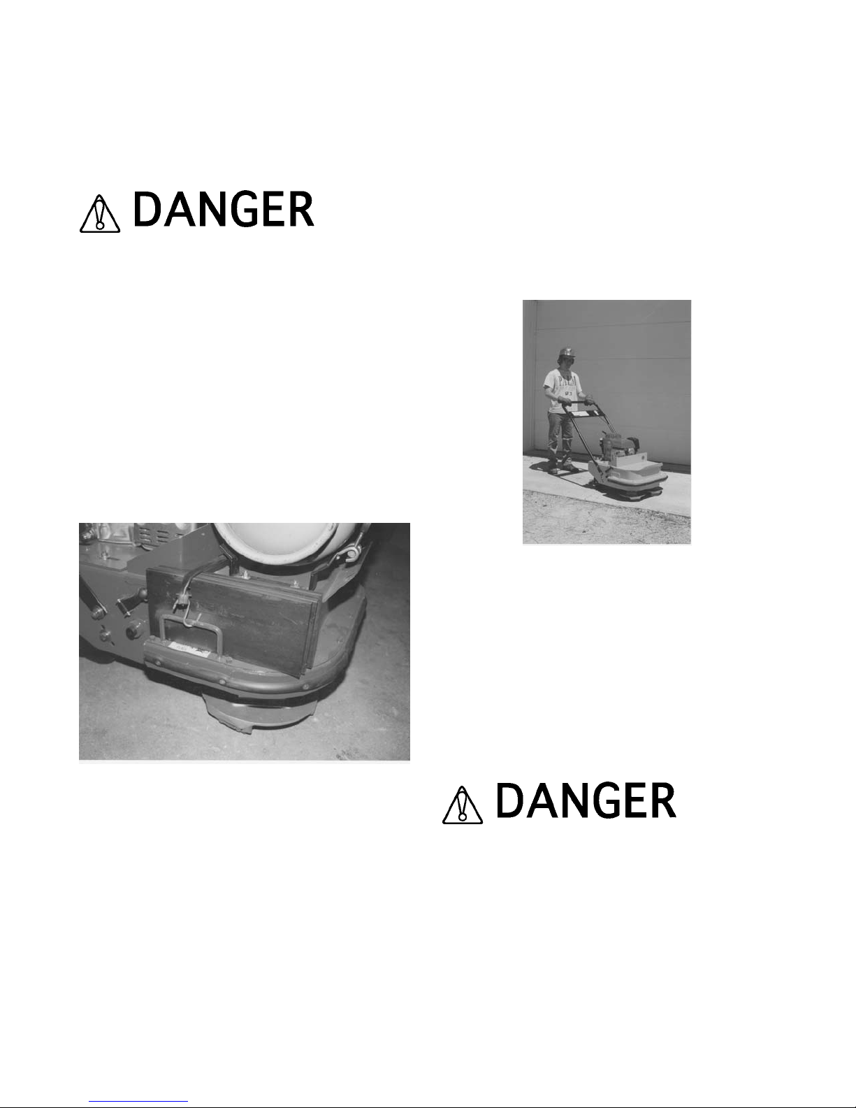
MACHINE CONTROL, PROPERTY DAMAGE
AND/OR PERSONAL INJURY. THIS PROCEDURE IS
ESPECIALLY IMPORTANT WHEN OPERATING THE
SURFACE GRINDER ON FLOORS AND/OR
SURFACES ABOVE GROUND LEVEL.
DO NOT OPERATE THE SG24/GHP PROPANE
CONVERTED SURFACE GRINDER WITH WEIGHT
APPLIED DIRECTLY UPON THE PROPANE
CYLINDER. PROPERTY DAMAGE AND/OR
PERSONAL INJURY CAN RESULT. IF EXTERNAL
WEIGHT IS REQUIRED, POSITION IT AROUND THE
CYLINDER AREA AND PROPERLY SECURE AS
ABOVE, FIGURE 37.
3) Proper operator posture and stance will enhance
operational safety and overall productivity, FIGURE 38.
For most job applications, operate the engine at
maximum, governed speed. Consult the material
supplied by the engine manufacturer and the
Specifications section for specific information.
FIGURE 37
4) The wide variety of potential work surface materials
along with the corresponding variety of job site
environments, makes it impossible to develop a
standardized operating procedure for the Surface
Grinder. Use of the Surface Grinder will require
constant trial and error testing until satisfactory results
are achieved. Experience gained over time and
common sense will help minimize the amount of
necessary testing. Many factors will directly affect the
operating parameters and/or techniques utilized for a
specialized job application. Some of these factors
include:
a) Work surface material yield and tensile values. As a
general rule, these values will determine material
removal rate per unit of time. Materials with high yield
and tensile values will characteristically resist/limit
material penetration. For such materials, the accepted
procedure is to make a number of multiple passes over
the work surface rather than attempt to make a single,
deep pass. The net effect is to actually increase
productivity: more material removed in less time. Other
added benefits to this technique are decreased
vibration, less operator fatigue and increased
component service life.
FIGURE 38
b) Higher material removal rates can sometimes be
achieved by making a series of shallow passes 90
degrees to each other to form a waffle like pattern. This
technique is especially useful when removing deeper
accumulations of rubber, paint, dirt debris, etc. from
industrial floors.
5) The grinding process on many work surface
materials can produce sparks, dust and other foreign
particle contamination.
SPARKS PRODUCED BY THE ACTIONS OF MULTIACCESSORY OPTIONS AGAINST THE WORK
SURFACE (FOR EXAMPLE: STRIKING ANCHOR
BOLTS) MAY COME IN CONTACT WITH
MATERIALS THAT CAN RESULT IN A FIRE AND/OR
EXPLOSION. THIS OCCURRENCE CAN RESULT IN
PROPERTY DAMAGE AND/OR PERSONAL INJURY.
SG24 GRINDER FORM GOM3259601, VERSION 1.2, AUTHORIZATION: DVR, PAGE: 36
Page 39

THE CREATION OF DUST AND OTHER FOREIGN
PARTICLE CONTAMINATION FROM THE
OPERATIONAL PROCESS CAN RESULT IN
PROPERTY DAMAGE AND/OR PERSONAL INJURY.
FOR SUCH OPERATING CONDITIONS, ALWAYS
WEAR A NIOSH/MSHA APPROVED DUST/MIST
RESPIRATOR. CONSULT APPLICABLE OSHA
REGULATIONS FOR SPECIFIC INFORMATION.
6) Dust and other particle contamination can be
controlled by the following methods:
a) The Surface Grinder is equipped with a 1-1/2, 2 or 3
inch outside diameter vacuum tube adaptor located at
the rear of the machine. An industrial type vacuum
system and front shield assembly can be attached to
the Surface Grinder to remove/control dust and other
particle contamination from the work surface. A hose
clamp is sometimes required to properly secure the
vacuum hose to the vacuum tube, FIGURE 39.
FIGURE 39
ALWAYS UTILIZE A VACUUM SYSTEM DESIGNED
TO OPERATE WITHIN THE SPECIFIC JOB SITE
REQUIREMENT. DUST MATERIAL CAN MEET
CLASS II OR CLASS III SPECIFICATIONS OF THE
NATIONAL ELECTRIC CODE® FOR HAZARDOUS
LOCATION CLASSIFICATIONS. CONSIDERATION
MUST ALSO BE GIVEN TO THE CREATION OF
HAZARDOUS TYPE MATERIALS REQUIRING
SPECIFIC DISPOSAL PROCEDURES. DETERMINE
THAT THE VACUUM SYSTEM IS PROPERLY
DESIGNED TO OPERATE WITHIN THESE
ATMOSPHERES. CONSULT CURRENT NATIONAL
ELECTRIC CODE®, OSHA AND ENVIRONMENTAL
PROTECTION AGENCY REGULATIONS FOR
SPECIFIC INFORMATION.
b) Water/sand slurry mixture applied directly to the
work surface can be an effective method of reducing
the effects of grinding and other material removal
processes. This method can be a productive
alternative when removing adhesives containing
asbestos. A negative effect of this method is that the
water/sand slurry mixture can be classified as a
hazardous material, requiring proper disposal
procedures.
7) Normal usage of the Surface Grinder will allow the
build-up and accumulation of work surface materials
on interior surfaces. It is highly recommended that both
the interior and exterior surfaces be properly cleaned
after the completion of each usage.
Failure to properly clean the interior surfaces of
the Surface Grinder can result in dried material
build-up and accumulation directly affecting
bearing service life.
EXERCISE EXTREME CAUTION WHEN UTILIZING
ANY SOLVENT TO REMOVE ACCUMULATED
MATERIALS FROM THE SURFACES OF THE
MACHINE AND RELATED COMPONENTS. MANY
SOLVENTS ARE FLAMMABLE. DO NOT SMOKE
OR INTRODUCE FLAME IN THE WORK AREA.
PROVIDE ADEQUATE VENTILATION AND WEAR
PROPER SAFETY APPAREL.
PROPERLY DISPOSE OF ALL ACCUMULATED
MATERIALS PER OSHA AND ENVIRONMENTAL
PROTECTION AGENCY CODES AND
REGULATIONS. MANY ACCUMULATED
SG24 GRINDER FORM GOM3259601, VERSION 1.2, AUTHORIZATION: DVR, PAGE: 37
Page 40

MATERIALS CAN BE CLASSIFIED AS
HAZARDOUS AND REQUIRE PROPER DISPOSAL
PROCEDURES. CONTACT THE APPLICABLE
GOVERNMENT AND/OR PRIVATE AGENCIES FOR
SPECIFIC INFORMATION.
8) On job applications where the work process creates
a considerable amount of loose material, it can
become almost impossible to determine proper
material removal depths and the extent of work already
accomplished. The problem can be compounded if a
vacuum system is not utilized. Loose material should
be removed by sweeping or other, appropriate
processes and the Surface Grinder utilized until
conditions again warrant removing the accumulated
material.
STOPPING THE SG24/E SERIES ELECTRICALLY
POWERED SURFACE GRINDER.
Stopping the Surface Grinder is accomplished by
moving the ON/OFF switch located on the operator
handle to the OFF position. For safety considerations,
it is also recommended that the extension cord be
disconnected from both the Surface Grinder and
electric power source whenever the Surface Grinder is
not in use on the job site.
STOPPING THE SG24/G SERIES GASOLINE
POWERED SURFACE GRINDER.
1) Stopping the Surface Grinder is accomplished by
moving the engine throttle lever to the idle speed
position (depicted by the turtle). Machines powered by
Honda engines can then be stopped by further moving
the engine throttle lever until the ignition system is
grounded.
2) Machines powered by other engines may utilize a
separate ON/OFF ignition switch. If so equipped, turn
the switch to the OFF position. Consult the material
supplied by the engine manufacturer for specific
information.
STOPPING THE SG24/GHP PROPANE
CONVERTED SURFACE GRINDER
1) Stopping the Surface Grinder is accomplished by
moving the engine throttle control lever to the idle
speed position (depicted by the turtle). Machines
powered by Honda engines can be then stopped by
further moving the engine throttle control lever until the
ignition system is grounded. Consult the material
supplied by the engine manufacturer for specific
information
2) Turn the Propane cylinder valve to the completely
closed position.
3) Inspect the Propane cylinder, all hoses, fittings and
conversion components for visible damage during use
and the potential for leaks. Replace any questionable
component with a factory approved replacement only.
OPERATIONAL PARAMETERS AND TECHNIQUES
FOR THE SG24 SERIES SURFACE GRINDER.
Application: All Models
Early Age Grinding
Early age grinding is an alternative to floating and
troweling. It gets it name from the fact that the concrete
is ground at an early age, after it has set but before it
has gained much structural strength. The process
usually involves the following steps:
1) Normal screeding of the floor.
2) Smoothing the floor surface with a skip float.
3) Cover the floor with polyethane sheeting.
4) Removing the sheeting and grinding the floor down
a uniform depth of approximately 1/32 inch within 24 to
48 hours of the initial pouring.
The C06 and C10 silicon carbide grinding stones are
usually used for the process, although the multi
segmented, dry diamond blades can be use as an
alternative with substantially greater productivity rates.
The main benefit of early age grinding is that it
eliminates late work in cold weather. With ordinary
finishing methods, a slab cast in the morning of a cold
weather day might not get finished troweled until very
late at night. With grinding, the construction crew is
able to leave the job at the end of a normal work day
and return 1 or 2 days later to finish the job. Early age
grinding may not reduce the total number of work
hours, but it usually eliminates the need for work at
overtime rates, which can substantially increase total
project costs.
One side benefit of early age grinding is that the
process demands less skill than conventional floating
and troweling. This makes it an attractive process
where skilled crew personnel may not be available. It is
also an excellent procedure for concrete floors that will
be eventually covered by carpet or an applied coating.
SG24 GRINDER FORM GOM3259601, VERSION 1.2, AUTHORIZATION: DVR, PAGE: 38
Page 41

Definitions of Floor Flatness and Levelness
The terms flatness and levelness have poorly
understood meanings in everyday speech, but have
important distinctions in floor construction.
Flatness is defined as planarity or lack of curvature. A
more simple definition is that a flat floor is smooth and
free of bumps and dips. An unflat floor is bumpy and
wavy. Levelness is defined as horizontality or lack of
slope. A level floor is horizontal. A floor that is unlevel
is sloped or tilted.
A floor can be flat, but still not level. Some floors are
specifically designed to be unlevel; they can be
intentionally sloped for drainage considerations. Very
few, if any, floors are specifically designed to be unflat.
Unfortunately, many turn out that way. Flatness and
levelness are both desirable, but have different
implications for the floor user. Flatness is critical where
the user's main concern is the behavior of wheeled
type vehicles. Levelness is critical where the user's
main concern is with fixed structures such as shelving,
racks and the placement of machine tools.
Exceptions exist, but for most users, flatness is more
important than levelness. The reasoning is that fixed
equipment can be shimmed or adjusted to
compensate. However, it is not as easy to adapt a
wheeled vehicle to a floor that is not flat enough to
allow for proper action.
Flatness and levelness also have different implications
for the floor contractor. Flatness is determined mainly
by finishing methods. Levelness is determined mainly
by the side forms.
Defined Versus Random Traffic Patterns
Floors are subject to two kinds of traffic patterns:
defined and random. On a defined traffic floor, vehicle
movement is confined to fixed paths. On a random
traffic floor, vehicles are free to roam, though inevitably,
some traffic patterns are used more than others.
The distinction is important because the two kinds of
traffic demand different methods of measuring surface
regularity. On a defined traffic floor, a continuous (or
nearly continuous) profile in each of the paths can be
measured. But where traffic is random, the possible
travel paths are infinite in number. What usually results
is statistical sampling; selected points or lines are
checked and assumed that they represent the whole
floor surface.
The highest degree of surface regularity is found
among the defined traffic floors. Defined traffic floors
allow the designer and contractor to focus on a limited
number of critical areas. When a defined traffic floor is
out of tolerance, it is relatively easy to identify the
defects for correction---usually by employing a grinding
process.
How to Define Surface Regularity
Since the middle 1980s, new methods of defining
surface regularity have been adopted as national
standards. Older methods will continue to be utilized,
although they are less effective. The following methods
will be discussed:
1) The F number system for random traffic floors
2) The TR34 system for defined traffic floors
Both methods are not of equal value. For random traffic
floors, F numbers provide the most complete and
consistent system. For defined traffic floors, the TR34
system is superior.
The F number system utilizes a pair of numbers to
define surface regularity. The flatness number, Ff, is
based upon the curvature over a horizontal distance of
24 inches. The levelness number, Fl, is based upon the
floor slope over a horizontal distance of 10 feet. The
standard test for F numbers is specified in ASTM
E1155 and/or most recent version.
With both Ff and Fl, higher numbers mean greater
surface regularity. Though the scale ranges from zero
to infinity, almost all floors have F numbers between 10
and 100 for both flatness and levelness. Since the
scale is linear, an Ff50 floor is exactly twice as flat as
an Ff25 floor.
Most F number specifications are written in a two tier
format. The overall F numbers apply to the floor taken
as a whole. The local F numbers apply to each
individual slab and are usually only one half to two
thirds the overall values.
The overall F numbers are not just simple averages.
ASTM E1155 covers how to combine F numbers.
The two tier format encourages contractors to achieve
good surface regularity while allowing for minor
defects. The attempt is to pour the entire floor to the
specified overall F numbers. If, for instance, the
construction crew has a bad day and fails to meet the
specified overall numbers for the slab, the slab can still
SG24 GRINDER FORM GOM3259601, VERSION 1.2, AUTHORIZATION: DVR, PAGE: 39
Page 42

be accepted provided it meets the specified local
numbers. Such an occurrence serves as a warning to
the crew that it must strive for a better performance on
later slabs, so as to bring the overall F numbers up to
the specified values. If a slab fails to meet even the
specified local numbers, it must be repaired or
replaced, but such failures seldom occur if all parties
understand what is expected from the start.
Designers are not obligated to use this two tier format.
Some designers specify a single F number pair (Ff and
Fl) which applies to each individual slab. But this also
raises the risk that slabs will be rejected.
FIGURE 40 depicts the overall and minimum F
numbers for various floor classes. The floor
classification is from the American Concrete Institute.
Although the F number system is only a few years old,
it offers these advantages:
a) The system controls both flatness and levelness.
b) There is a standard test method.
c) The system recognizes the statistical nature of
profile testing on random traffic floors.
d) The system is infinitely variable.
FIGURE 40
One of the major limitations of the F number system is
that it does not control the surface regularity at joints.
Because joints are statistical anomalies, the standard
test method forbids measurements within 24 inches.
The designer specifying by F number has two methods
to accommodate the problem. The first solution is to
locate joints at locations where surface regularity is not
important. The second solution is to design
specifications for the joints themselves.
The TR 34 Tolerances for Defined Traffic Floors
The TR 34 System divides defined traffic floors into
three categories:
a) Superflat
b) Category 1
c) Category 2
For each category, the TR 34 System specifies limits
for three properties:
Property 1 is the difference in elevation between two
points 12 inches apart, measured in the direction of
vehicle traffic. This is the levelness tolerance.
Property 2 is the difference in slope over 24 inches
measured in the direction of vehicle traffic. This is the
flatness tolerance. It is identical as the 24 inch
curvature utilized in the F number system.
Property 3 is the difference in elevation between
opposite points in the left and right wheel path,
measured perpendicular to the direction of vehicle
traffic. As with Property 1, it is a levelness tolerance.
The TR 34 System specifies different values for
Property 3 depending upon whether the distance
between left and right wheel paths is more or less than
5 nominal feet.
The Superflat category is intended for very narrow
aisle warehouses where the highest standards are
required. Category 1 is suggested for very narrow aisle
warehouses where the vertical lift height is between 26
and 43 feet. Category 2 is for very narrow aisle
warehouses where the vertical lift height is under 26
feet and the use of low rise, automatically controlled
vehicles. No matter which category of surface
regularity is specified, it is accomplished by measuring
elevations on 12 inch centers. This is very similar to an
F number survey, but with an important distinction. In
an F number survey, the elevation profiles are made on
the floor at random. With the TR 34 System, the survey
measurements are made on the actual paths of the
vehicles that will utilize the floor.
Improving the Wear Resistance of Concrete Floors
by Grinding with the SG24 Series Surface Grinder
Poor wear resistance can often be traced back to a
surface that is weaker than underlying levels of the
pour. This occurrence can result from bad finishing
techniques, improper curing or early freezing.
SG24 GRINDER FORM GOM3259601, VERSION 1.2, AUTHORIZATION: DVR, PAGE: 40
Page 43

Where surface weakness is a problem, grinding can be
a solution. The process is similar to the early age
technique. The grinding depth is typically 1/16 to 1/8
inch. A large project should not be attempted until a
small test area has proven that the technique will
produce the desired results. Usually only a square yard
of floor is ground with the normal wear tests performed.
Repair costs can be minimized by grinding only those
floor areas that accommodate traffic. For example, in a
pallet rack warehouse, it may be necessary to grind
only the aisle areas and not under any of the racks.
The grinding process can adversely affect the surface
regularity. Where specific properties are important, it
may be necessary to survey the floor during the
grinding process to ensure that flatness and levelness
specifications are maintained.
Cleaning Concrete Floors to Improve the Wear
Resistance with the SG24 Series Surface Grinder
Clean concrete floors have a longer service life than
dirty, poorly maintained floors. Loose debris produces
three-bodied wear by allowing particles to roll between
the traffic and the floor surface. With some types of
debris, especially when lodged in vehicle wheels, wear
can be immediate and severe.
The SG24 Series Surface Grinder can be utilized with
a number of multi accessories to clean and extend
concrete floor service life. The SCRAPE-R-TACH®
floor coatings removal system readily removes food, oil
and rubber accumulations from high traffic floor areas.
The Clean Sweep™ silicon impregnated, rotary
brushes along with a biodegradable detergent applied
to floors removes ground in dirt and debris from shop
and industrial floors. Dry diamond segmented discs
and blocks can be utilized to remove surface
imperfections.
Service
PREVENTATIVE MAINTENANCE CHECK LIST.
Application: All Models
The normal operation of the Surface Grinder produces
extreme dirt and dust, along with levels of random
vibration. Before operating the Surface Grinder, the
following service list should be accomplished. This list
is for reference only and is not intended to be all
inclusive. Other subject areas can be added at the
discretion of the owner(s) and/or operator(s):
1) Check all fasteners for proper torque values. If a
fastener requires retorquing, consult a torque chart for
proper value. Properly discard and replace any worn
fastener with a factory approved, replacement part
only.
2) Check the V-belts for wear. Adjust or replace as
necessary. Check pulleys for wear and proper
alignment. Many loose materials created as a result of
operating processes can be extremely abrasive.
3) Keep the Surface Grinder clean. Wash the unit after
each use. Keep loose materials from accumulating
around engine cooling fins. Determine that the interior
sections of the frame are free of material build-ups.
Such build-ups can restrict the operating process and
present a potential safety hazard. Clean and remove
any material build-up from the Surface Grinder after
each use.
4) Engine service life can be extended with proper air
cleaner maintenance. Consult the material supplied by
the engine manufacturer for specific information.
5) Check for proper oil level. Always use clean, high
quality engine oil. Change oil as required. Consult the
material supplied by the engine manufacturer for
specific information.
6) Remove material accumulations from the exterior
surfaces of the electric motor. The electric motor is a
totally enclosed, fan cooled (TEFC) design. Keep the
fan fins clear of material accumulations to enhance air
flow over the motor exterior for cooling purposes.
SG24 GRINDER FORM GOM3259601, VERSION 1.2, AUTHORIZATION: DVR, PAGE: 41
Page 44

DO NOT PERFORM PREVENTATIVE
MAINTENANCE CHECKS WITH THE ENGINE OR
ELECTRIC MOTOR RUNNING. STOP THE POWER
SOURCE AND DISCONNECT THE SPARK PLUG
OR EXTENSION CORD BEFORE PERFORMING
ANY MAINTENANCE TO THE SURFACE GRINDER.
IF GASOLINE ENGINE POWERED, RECONNECT
THE SPARK PLUG BEFORE RESTARTING THE
ENGINE. IF ELECTRIC MOTOR EQUIPPED, TURN
THE ON/OFF SWITCH TO THE OFF POSITION
BEFORE RECONNECTING THE EXTENSION
CORD. IMPROPER PROCEDURES CAN RESULT IN
PROPERTY DAMAGE AND/OR PERSONAL INJURY.
CHECKING V-BELT TENSION AND ALIGNMENT.
Application: All Models
Proper V-belt tension and alignment are essential for
smooth transmission of horsepower and extended
service life. Improper tension and alignment will
accelerate V-belt wear and contribute to decreased
productivity. The V-belt is tensioned at the factory with
the maximum recommended tension force. Check the
belt tension at least two times during the first day of
operation as there will normally be a rapid decrease in
belt tension until it has been run in. Check the belt
tension every eight hours of operation thereafter and
maintain tension within the recommended range. The
correct operating tension for a V-belt drive is the lowest
tension at which it will not slip under peak load
conditions.
Tools Required:
1 each, 16 inch minimum length straightedge
1 each, 10 lbs minimum capacity, tension scale or belt
tension tool
1) If the Surface Grinder is powered by an engine,
disconnect the spark plug wire. If powered by an
electric motor, disconnect the extension cord or
Surface Grinder from the power source.
2) Position the Surface Grinder on a suitable work
bench with the V-belts approximately at waist level.
3) Remove the rubber latches and slide the belt guard
away from the engine/electric motor until it clears the
catch mechanism. If the Surface Grinder is equipped
with a Propane converted engine, determine that the
Propane cylinder valve is closed before uncoupling the
hose. Remove the belt guard from the main frame.
Clean the inside of the belt guard with an appropriate
solvent. Check for signs of wear and damage.
Observe all applicable safety precautions for the
solvent.
4) Check the belt tension using the spring scale or belt
tension tool midway between the engine clutch pulley
and the transmission pulley. Belt tension should
measure approximately 0.22 inch at 3-1/4 to 4-3/8
lbs. measured force range, FIGURE 41. If tension is
within specifications, proceed to Step 5. If tension is
not within specifications, refer to INSTALLING A
REPLACEMENT V-BELT for specific information.
FIGURE 41
5) Belt alignment is checked with the straightedge.
Place the straightedge squarely against the
transmission pulley. Properly aligned pulleys should
also place the straightedge squarely against the
engine/motor pulley. Remove the straightedge and
rotate the engine pulley 120 degrees, FIGURE 42.
Recheck alignment with the straightedge. Repeat the
process until the engine/motor pulley is rotated a full
360 degrees. Maximum allowable misalignment is + 1/32 inch. If pulley alignment is not within
specifications, refer to INSTALLING A
REPLACEMENT V-BELT for specific information.
6) Install the belt guard to the main frame. Determine
that all safety related decals affixed to the belt guard
SG24 GRINDER FORM GOM3259601, VERSION 1.2, AUTHORIZATION: DVR, PAGE: 42
Page 45
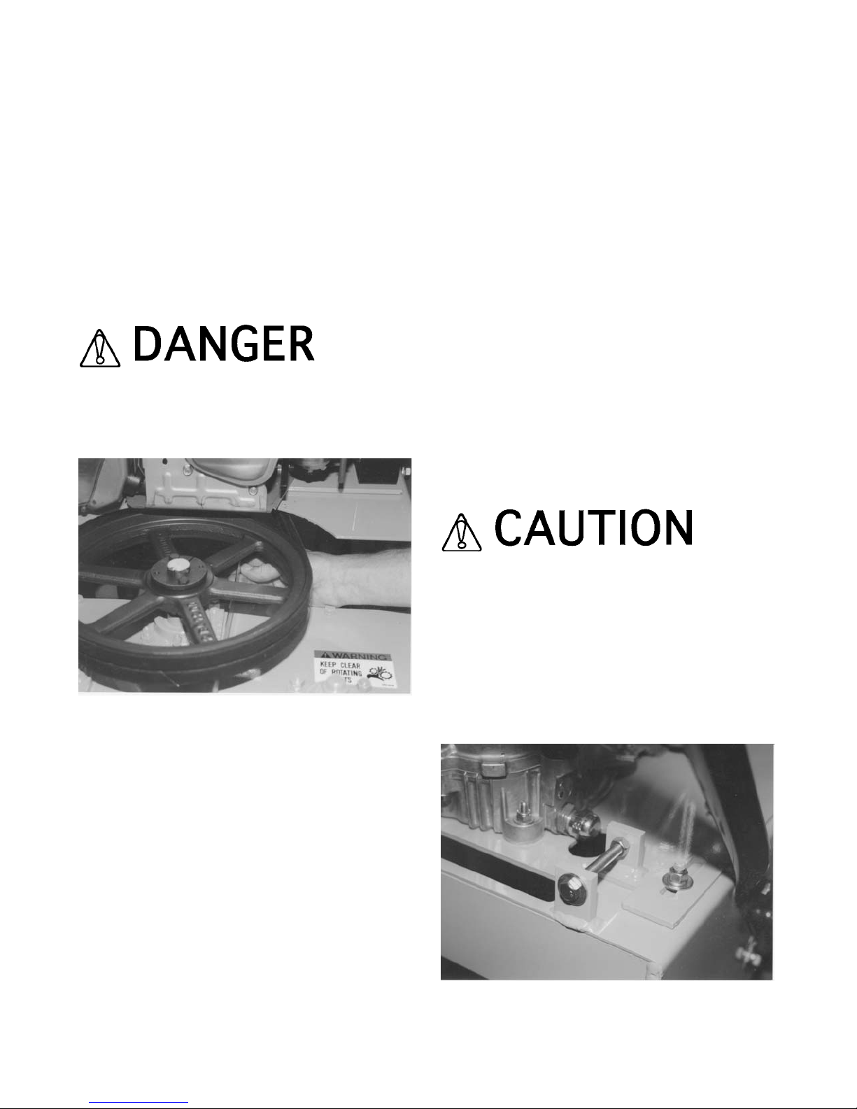
are fully readable. If any decal is not fully readable,
replace with a factory approved, replacement part only.
If the Surface Grinder is equipped with a Propane
converted engine, properly install the Propane cylinder
and recouple the hose.
7) If the Surface Grinder is powered by an engine,
reconnect the engine spark plug wire. If powered by an
electric motor and the machine is to be used
immediately, reconnect the extension cord or Surface
Grinder to the power source. Determine that the
ON/OFF switch located on the operator handle is in the
OFF position.
UNEXPECTED MACHINE START UP CAN RESULT
IN PROPERTY DAMAGE AND/OR PERSONAL
INJURY.
FIGURE 42
INSTALLING A REPLACEMENT V-BELT,
CENTRIFUGAL CLUTCH OR PULLEY.
Application: As Specified
Tools Required:
1 each, 7/16 wrench
2 each, 1/2 wrenches
1 each, 9/16 wrench
1 each, 5/32 Allen wrench
1 each, 16 inch minimum length straightedge
1 each, 10 lbs minimum capacity, tension scale or belt
tension tool
1 each, torque wrench, 35 ft lbs (47 Nm.) capacity with
7/16 inch and 9/16 inch sockets
1 each, belt tension tool
Parts Required:
2 each, PN B50 V-belt (if required)
1 each, PN SG24-0520 Pulley Assembly (if required)
1 each, Pulley Assembly (if required):
PN SG24-0510 (50Hz only)
PN SG24-0500 (60Hz only)
1 each, PN SG24-0320 Centrifugal Clutch Assembly (if
required)
1) Position the Surface Grinder on a suitable work
surface with the V-belts approximately at waist level.
2) If the Surface Grinder is equipped with a Propane
converted engine, determine that the Propane cylinder
valve is closed before uncoupling the hose. Remove
the rubber latches and slide the belt guard away from
the engine/electric motor until it clears the catch
mechanism. Remove the belt guard from the main
frame. Clean the inside of the belt guard with an
appropriate solvent. Check for signs of wear and
damage. Secure in a proper storage area.
Observe all applicable safety precautions for the
solvent.
3) Using the 1/2 inch wrenches, loosen the
engine/motor mounting plate cap screws.
4) With the same wrenches, rotate the engine take-up
cap screws counterclockwise to loosen the V-belts and
allow the engine/electric motor to slide toward the front
of the main frame, FIGURE 43.
FIGURE 43
SG24 GRINDER FORM GOM3259601, VERSION 1.2, AUTHORIZATION: DVR, PAGE: 43
Page 46
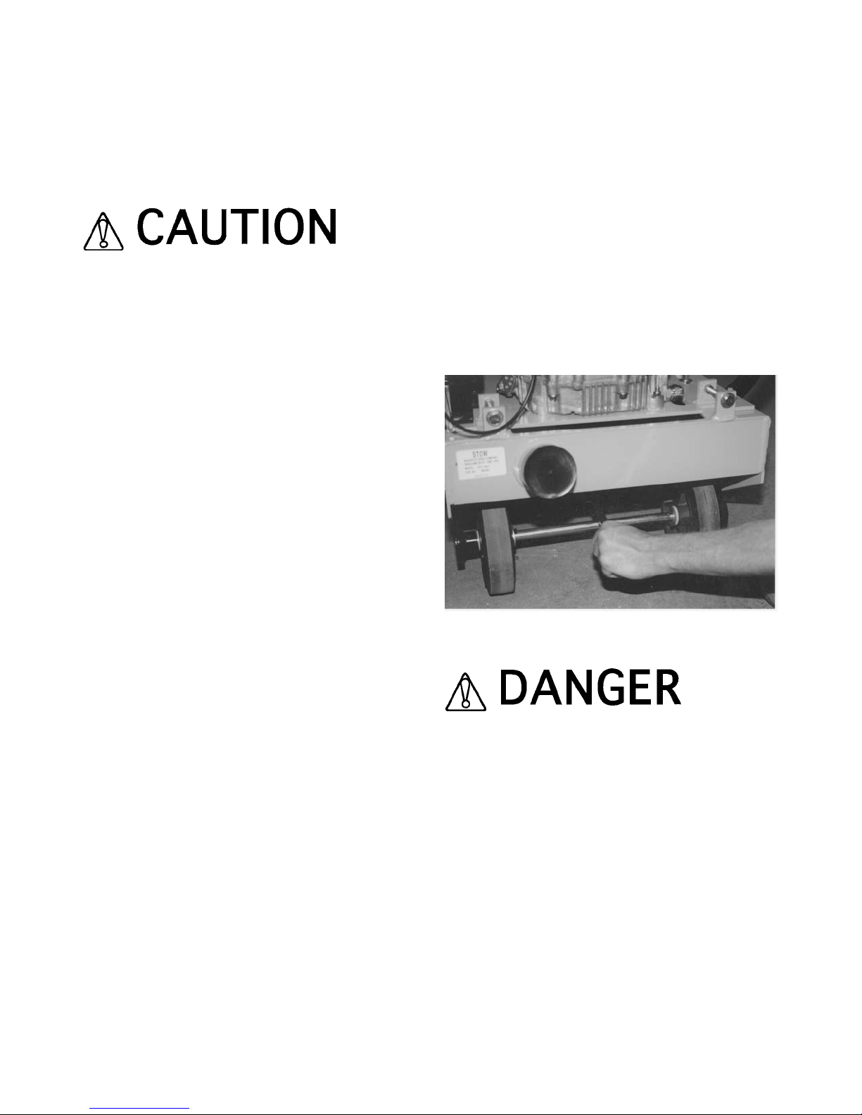
5) Remove the worn V-belts. Inspect the
engine/electric motor and transmission pulleys for
wear and damage. Install the replacement belts, PN
B50 in pairs. The Surface Grinder utilizes two V-belts.
Always install replacement belts in matched pairs.
Never replace just one of the V-belts.
Do not operate the Surface Grinder with only one
V-belt installed. One V-belt is not capable of
transmitting proper horsepower and torque levels
to the multi-accessory discs.
a) Do not install replacement belts if the pulleys have
excessively worn grooves. Such pulleys should be
replaced to insure proper belt fit. Operating the V-belts
in worn pulley grooves will accelerate wear, reduce
horsepower and torque levels and significantly reduce
component service life.
b) A V-belt should never be forced over a pulley. More
belts are broken from this cause than from actual
failure in service.
c) Keep the belts as clean and free of foreign material
as possible. Do not use belt dressing.
6) The centrifugal clutch assembly utilized on both the
gasoline engine powered and Propane converted
Surface Grinders is designed to deliver an extended
service while requiring minimal service. However, long
term use of the Surface Grinder can allow the
accumulation of fine dusts and powders within the
clutch assembly. These dusts and powders can
dramatically reduce the capacity of the the clutch drum
bearing, resulting in the following operational
characteristics:
a) When operating the engine at idle speed, the
centrifugal clutch assembly will not fully disengage,
allowing the multi accessory discs to rotate at low
speed.
b) When the engine is advanced to and/or from the idle
speed position, erratic machine movement or
"grinding" and "thrashing" noises from the clutch area
are detected.
In many cases, clutch assembly removal, a cleaning of
the bearing surfaces, and reassembly will solve the
problem.
7) Rotate the take-up cap screws clockwise until the Vbelts have enough tension to not allow them to fall off
the centrifugal clutch and/or pulleys.
8) Using the 9/16 inch wrench, remove the retaining
cap screw from the engine crankshaft. Using the 5/32
inch Allen wrench, loosen the two set screws located
near the snap ring. The clutch can now be removed
from the engine crankshaft. FIGURE 44.
9) The centrifugal clutch is comprised of a rotor/shoe
assembly, a drum/pulley assembly, a thrust washer
and retaining snap ring.
a) Using the snap ring pliers, remove the snap ring
from the clutch assembly, FIGURE 45.
FIGURE 44
WEAR SAFETY EYEWEAR AND OTHER
APPROPRIATE APPAREL WHEN DISASSEMBLING
THE CENTRIFUGAL CLUTCH ASSEMBLY.
CAUTION ALL ONLOOKERS REGARDING THE
POTENTIAL FOR FLYING DEBRIS. FAILURE TO
EXERCISE PROPER SAFETY PRECAUTIONS CAN
RESULT IN PROPERTY DAMAGE AND/OR
PERSONAL INJURY.
SG24 GRINDER FORM GOM3259601, VERSION 1.2, AUTHORIZATION: DVR, PAGE: 44
Page 47
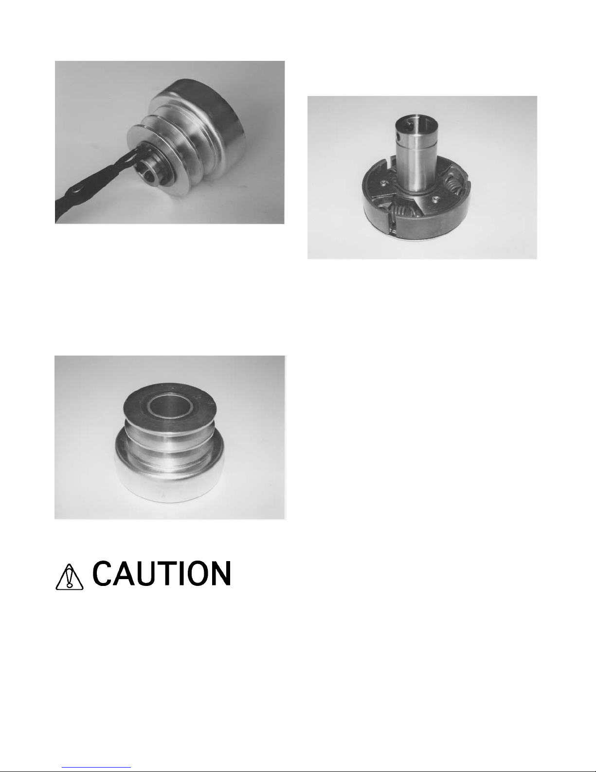
FIGURE 45
b) Disassemble the rotor/shoe assembly and
drum/pulley assemblies. Clean each component with
an appropriate safety solvent. Pay special attention to
the inside diameter bore of the drum/pulley assembly
bearing. Inspect for signs of excessive wear and
damage which can allow the rapid formation of foreign
material accumulation, FIGURE 46.
FIGURE 46
Observe all applicable safety precautions for the
solvent.
c) The clutch rotor springs and shoes are relatively
maintenance free and should deliver many hours of
trouble free operation before complete replacement is
required. Severely discolored springs and shoes are
signs of excessive clutch slippage caused by improper
operation techniques, FIGURE 47.
FIGURE 47
10) Reassemble the components in reverse order and
install the clutch assembly on the engine crankshaft
with the pulley facing toward the engine.
11) Reinstall the V-belts to the transmission and clutch
pulleys and tighten as outlined in CHECKING V-BELT
TENSION AND ALIGNMENT.
REPLACING THE LORD® TYPE ELASTOMERIC
MOUNTS ON THE MULTI-ACCESSORY DISCS.
Application: All Models
Lord® type elastomeric rubber mounts are utilized to
allow each multi-accessory disc to maintain full contact
with the work surface. The rubber mounts afford a
constant flex rate for each multi-accessory disc
throughout its service life. The rubber compound is
resistive to the effects of ultraviolet radiation and most
common chemicals encountered when operating the
Surface Grinder .
During the manufacturing process, the rubber mounts
are pressed into specially machined cavities in the disc
mounting plates. Under normal usage and job
applications, the Lord® type rubber mounts will deliver
appropriate performance for the expected service life
of the Surface Grinder. However, an attachment
mounted in the multi-accessory disc that directly
strikes a vertical floor obstruction with sufficient impact
force can cause one or more of the mounts to become
separated from the mounting plate. This occurrence
will not allow the multi-accessory disc to maintain full
contact with the work surface. This occurrence is also
SG24 GRINDER FORM GOM3259601, VERSION 1.2, AUTHORIZATION: DVR, PAGE: 45
Page 48

intended to protect the transmission gears and
bearings from costly damage and the operator from an
impact force that could cause personal injury.
Tools Required:
1 each, 5/16 Allen wrench
2 each, 5/8 wrenches
1 each, arbor press of sufficient capacity and stability
Parts Required:
PN J-6250-2 Elastomeric Mount (as required)
1 container each: PN 80 Installation Lubricant (or
approved equivalent)
1) If the Surface Grinder is powered by an engine,
disconnect the spark plug wire. If powered by an
electric motor, disconnect the extension cord or
Surface Grinder from the power source.
2) Position the Surface Grinder on a suitable work
bench with the multi-accessory discs at waist level.
3) If the Surface Grinder is equipped with a Propane
converted engine, determine that the Propane cylinder
valve is closed before uncoupling the hose. Remove
the rubber latches and slide the belt guard away from
the engine/electric motor until it clears the catch
mechanism. Remove the belt guard from the main
frame. Clean the inside of the belt guard with an
appropriate safety solvent. Check for signs of wear and
damage. Secure in a proper storage area.
Observe all applicable safety precautions for the
solvent.
4) Tilt the Surface Grinder back until the operator
handle comes in contact with the surface. The surface
Grinder may not be in a stable position in this
configuration. To minimize the possibility of property
damage and/or personal injury, apply an appropriate
weight to the handle to stabilize the Surface Grinder,
FIGURE 48. Other means can also be utilized to
support the frame and provide proper machine stability.
Appropriate wheel chocks are recommended. Follow
the instructions for this procedure as outlined in
INSTALLING A MULTI-ACCESSORY ATTACHMENT
(not including multi-segmented, dry diamond blades)
IN THE COUNTERROTATING DISCS.
5) Utilizing the Allen wrench, remove the affected
aluminum multi-accessory disc (if still attached) from
the Surface Grinder.
6) Utilizing the 9/16 inch wrenches, remove the cap
screws that retain the Lord® rubber mounts to both the
mounting plate and transmission shaft.
FIGURE 48
7) Inspect the appropriate cavities in the mounting
plate for wear and damage. Any nick or burr must be
remove by the use of an appropriate file, followed by
the use of 240 grit sandpaper FIGURE 49.
FIGURE 49
8) Apply the installation lubricant to the exterior surface
of the elastomeric mount to minimize damage when
pressing into the mounting disc. If the factory supplied
lubricant is not available, an acceptable alternative is
the use of common liquid soap.
SG24 GRINDER FORM GOM3259601, VERSION 1.2, AUTHORIZATION: DVR, PAGE: 46
Page 49

Do not install an elastomeric mount without the
use of an approved lubricant. Installation without
an approved lubricant can produce tares in the
mount, resulting in substandard operational
performance and service life.
9) Support the elastomeric mount, socket and
mounting plate as depicted in FIGURE 50. The
mounting plate must be suspended from the arbor
press to allow the mount to clear when the pressing
process is completed. A short section of 1-1/2 inch
inside diameter steel tubing can be utilized for this
purpose. Using the arbor press, apply a steady force
in a straightline direction to the mount until it fully
penetrates the cavity in the mounting disc. Do not
attempt to push the elastomeric mount through the
mounting disc with excessive force. Damage to the
elastomeric mount will result.
10) Reassemble the mounting discs to the
transmission shaft.
11) Reassemble the mounting plate to the mounting
disc.
12) Reassemble the aluminum multi-accessory disc to
the mounting plate.
13) Check to determine that the replacement
elastomeric mounts allow for proper position of the
aluminum multi-accessory disc. If the elastomeric
mounts are not properly positioned, they will require
removal and reinstallation. The removal process can
produce tares and abrasions in the mount that will
require a new replacement.
FIGURE 50
LUBRICATION REQUIREMENTS.
Application: All Models
Parts Required:
1 each, standard grease gun filled with one of the
following: ESSO Beacon 325, Shell Alvania
#2, Chevron SRI, or equivalent
1 each, container of dry film lubricant
1) Lubricate the caster wheel bearings with a dry film
lubricant only. Dry film lubricants dry immediately upon
contact. Use sparingly. Excess lubricant will attract the
fine grained, powdered materials described and
directly affect bearing service life.
Do not lubricate the caster wheels with any type of
grease material. Grease will attract foreign material
accumulations that can accelerate bearing wear.
2) The transmission gears are supported by extra
capacity, ball bearing units. Bearings are lubricated at
the time of manufacture and do not require additional
servicing when placing the unit in initial service. Zerk
grease fittings can promote improper service
schedules and an excessive amount of over
lubrication. Excess grease escaping from around the
bearing insert seals will attract foreign material
accumulations that can drastically shorten seal service
life. Excessive amounts of grease in the bearing race
cavity can actually increase friction and resulting heat
increases that can also dramatically shorten bearing
service life.
3) The transmission gears are lubricated at the time of
assembly with approximately 24 ounces of Lubriplate
GR132 grease or equivalent. This lubricant has an EP
additive to better allow it to cling to the gears. The
transmission should not require additional lubrication
or the lubrication to be changed until service work to
the gears is performed.
4) Standard bearing greasing intervals will range from
once every 8 hour work day to approximately once
every work week. Always maintain sufficient grease
around the circumference of the bearing insert to
provide its self-aligning feature and prevent the
formation of corrosion.
5) Do not apply belt dressing materials to the V-belts
SG24 GRINDER FORM GOM3259601, VERSION 1.2, AUTHORIZATION: DVR, PAGE: 47
Page 50

for the purpose of minimizing slippage. These products
typically attract foreign material accumulations that can
accelerate component wear. Excessive V-belt slippage
can be eliminated with proper V-belt tension and
alignment.
ELECTRIC MOTOR SERVICE.
Application: SG24/E Series Surface Grinder
The electric motor is capable of operating for many
years with a reasonably small amount of maintenance.
Before attempting to service the motor, disconnect the
Surface Grinder from the power source. Clean the
motor surfaces periodically, preferably with a vacuum
cleaner. Heavy accumulations of dirt and lint will result
in overheating and premature failure of the motor.
The electric motor is equipped with higher capacity ball
bearings and under normal service and ambient
temperatures, should not require relubrication for many
years. If you feel that the motor requires relubrication,
contact the local representative of the motor
manufacturer for specific information.
The seals utilized with the motor are intended to deliver
a longer service life in a concrete dust environment.
When replacing the seals, utilize only components
meeting the original factory specifications.
ENGINE SERVICE.
Application: SG24/G Series and SG24/GHP Surface
Grinder.
Consult the material supplied by the engine
manufacturer for specific service and maintenance
information regarding:
1) muffler
2) spark plug
3) air filter system
4) carburetor adjustment
5) ignition system
6) short and long term storage
7) maximum governed speed
8) emission standards
Keep this information stored with the Operator's
Manual for the Surface Grinder so it will always be
available for use when the engine requires service or
maintenance. A properly maintained engine will add
considerably to the service life and overall productivity
of the Surface Grinder.
Troubleshooting
ELECTRIC MOTOR
.
Application: SG24/E Series Surface Grinder.
MOTOR FAILS TO START
ON/OFF switch in the OFF position. Turn the switch to
the ON position.
Improper voltage selection. Determine the available
voltage value from the power source. Move the voltage
selection switch located on the motor to the proper
selection.
Surface Grinder and/or extension cord is not plugged
into the power source. Determine that all electrical
connections have been properly made. The NEMA 620 Series cap and receptacle set is of a twist lock
configuration and requires a twist motion to ensure a
proper connection.
Improper extension cord size and capacity. Operate
the Surface Grinder with copper stranded, 8 AWG or
larger extension cords. Improper extension cord size
and capacity will result in significant heat rise and
corresponding voltage and amperage drop.
Thermal protection device activated. To protect the
motor against heat related damage, an automatic
thermal protection switch is provided near the voltage
selection switch. High operating temperatures will
activate the switch and shut the motor off. After the
motor has cooled to an acceptable temperature level,
depress the switch to restart.
MOTOR LOSES POWER
Improper extension cord size and capacity. Replace
with cords meeting the required specifications.
Excessive extension cord length. Even with proper
extension cord size and capacity, excessive cord
length can reduce the available voltage and amperage
to the motor. Measure the available voltage to the
motor where the extension cord connects to the
Surface Grinder with a voltmeter. Reduce the
extension cord length as required to achieve the
minimum voltage operating specification as required
by the motor manufacturer.
Insufficient available voltage and amperage at the
power source. Measure the available voltage at the
SG24 GRINDER FORM GOM3259601, VERSION 1.2, AUTHORIZATION: DVR, PAGE: 48
Page 51

power source (usually a receptacle) with a voltmeter. If
the available voltage is below the minimum operating
specification as required by the motor manufacturer,
utilize an alternative power source.
Improper motor cooling. See ELECTRIC MOTOR
SERVICE.
Excessive load to the motor. See OPERATING THE
SURFACE GRINDER ON THE JOB SITE.
ENGINE.
Application: SG24/G Series and SG24/GHP
Propane Converted Surface Grinders
ENGINE FAILS TO START
Ignition switch in OFF or cut off position. Place switch
in the ON position or move throttle control lever to the
ignition operational position.
Incorrect carburetor/fuel ignition system adjustment.
See Service section.
Air filter blocked. See Service section.
Ignition wire to spark plug loose or disconnected.
Reconnect.
Application: SG24/G Series Surface Grinder
Fuel supply exhausted. Refill the fuel tank.
Application: SG24/GHP Propane Converted
Surface Grinder
Propane cylinder valve closed. Open valve.
Propane cylinder empty. Refill cylinder.
Spark plug fouled. Replace spark plug.
Improper priming technique. See STARTING THE
SG24/GHP PROPANE CONVERTED SURFACE
GRINDER ON THE JOB SITE.
ENGINE LOSES POWER
Incorrect carburetor/fuel injection adjustment. See
Service section.
Excessive carbon accumulation in combustion
chamber. See Service section.
Excessive material build-up around the cooling fins.
See Service section.
Application: SG24/G Series and SG24/GHP
Propane Converted Surface Grinders
Water in fuel supply. Drain and replace fuel.
Fuel tank breather vent closed (if so equipped). Open
vent.
Air filter blocked. See Service section.
Application: SG24/GHP Propane Converted
Surface Grinder
Propane cylinder valve closed. Open valve.
OPERATIONAL PROBLEMS.
Application: All Models
UNEVEN MULTI-ACCESSORY ATTACHMENT WEAR
Incorrect installation of the attachment in the aluminum
disc. See INSTALLING A MULTI-ACCESSORY
ATTACHMENT ON THE COUNTERROTATING
DISCS.
Worn or damaged gimbal head Lord® rubber mounts.
Replace mounts.
Accumulation of foreign material on the multiaccessory attachment. Clean and/or replace the
attachment components as necessary.
Flails and spacer washers are mounted too tight on the
scarifier frame. Remove and/or replace flails and
spacer washers. See MULTI-ACCESSORY
ATTACHMENTS AND APPLICATIONS.
EXCESSIVE JUMPING ON THE WORK SURFACE
Incorrect installation of the attachment in the aluminum
counterrotating disc. See INSTALLING A MULTIACCESSORY ATTACHMENT ON THE
COUNTERROTATING DISCS.
Worn or damaged gimbal head Lord® rubber mounts.
Replace mounts.
Loose gimbal head fasteners. Retorque fasteners as
required.
SG24 GRINDER FORM GOM3259601, VERSION 1.2, AUTHORIZATION: DVR, PAGE: 49
Page 52

ACCELERATED V-BELT WEAR
Misaligned and/or improperly tensioned pulleys.
Readjust pulleys and V-belt. See Service section.
Worn pulleys. Replace pulleys as required. See
INSTALLING A REPLACEMENT V-BELT OR PULLEY.
Improper V-belt. Replace with a name brand B50
series V-belt. Never replace a single belt. Always
replace both V-belts at the same time in matched sets.
See INSTALLING A REPLACEMENT V-BELT OR
PULLEY.
ACCELERATED BEARING WEAR AND/OR FAILURE
Misaligned and/or improperly tensioned pulleys.
Readjust pulleys and V-belts. See Service section.
Bent transmission input or output shaft. Replace
affected shaft(s).
Improper lubrication. See LUBRICATION
REQUIREMENTS.
UNEVEN GRINDING ACTION
Excessive material build-up on the caster wheel face
surface. Remove material.
Excessive caster wheel bearing wear. Replace the
caster wheel. Excessive axle wear. Replace axle.
Flails and/or spacer washers are mounted too tight on
the scarifier frame. Remove and/or replace flails and
spacer washers. See MULTI ACCESSORY
ATTACHMENTS AND APPLICATIONS.
Mixing new and worn flails, silicon carbide stones, etc.
Remove and replace with components of the same,
approximate size and diameter. See MULTI
ACCESSORY ATTACHMENTS AND APPLICATIONS.
Storage
Application: All Models
Proper procedure for long term storage of the Surface
Grinder will protect it against the effects of corrosion
and damage. If the Surface Grinder is not to be
operated for a period of 30 days or more, proceed to
store as follows:
1) Clean all accumulated foreign material from the
Surface Grinder utilizing an appropriate safety solvent.
Observe all applicable safety precautions for the
solvent.
2) Follow the procedure as outlined in the material
supplied by the engine manufacturer describing long
term storage for the engine.
3) Check all visible parts for wear, breakage or
damage. Order any part required to make the
necessary repair. This will avoid a needless delay
when operating the Surface Grinder at next use.
4) Apply a dry film lubricant to all exposed metal
components to prevent the formation of rust.
5) Store the Surface Grinder inside. If the Surface
Grinder must be stored outside, protect it with a
suitable covering.
Specifications
FRAME.
STRUCTURE Unitized, welded steel plate.
DRIVE REDUCTION SYSTEM B50 Series
belt/pulley/spur gear
transmission.
MAXIMUM GRINDING WIDTH 24 inches (610 mm).
OVERALL MACHINE WIDTH 27-1/2 inches (699 mm).
SG24 GRINDER FORM GOM3259601, VERSION 1.2, AUTHORIZATION: DVR, PAGE: 50
Page 53

OVERALL MACHINE LENGTH 3 inches (1346 mm).
TYPICAL OPERATOR HANDLE HEIGHT 40 inches
(1066 mm).
VACUUM CLEANER CONNECTION 1 -1/2 inch
(51 mm), 2 inch (51 mm) or
3 inch (76 mm) diameter.
GENERAL.
SG24/E BASIC WEIGHT 250 lbs (114 kg).
SG24/G BASIC WEIGHT 300 lbs (136 kg).
SG24/GHP BASIC WEIGHT 350 lbs (159 kg).
SG24/E ELECTRIC MOTOR 2 hp, 3450 RPM, 16.8
amperes @ 115 VAC, 60 Hz, or 8.4 amperes @ 230
VAC, 60 Hz, switchable when the motor is not in
operation. The electric motor requires a clean (no other
electric products on the same circuit) 20 ampere
capacity circuit to properly function on 115 VAC, 60 Hz
or 10 ampere capacity circuit to properly function on
230 VAC, 60 Hz.
SG24/G ENGINE 11 hp (82 kw) nominal, industrial
quality, 4 cycle engine, 3450 RPM nominal maximum
governed speed.
SG24/GHP ENGINE 11 hp (82 kw) nominal, industrial
quality, 4 cycle engine, 3450 RPM nominal maximum
governed speed, converted for use with Propane. The
BTU content of Propane reduces the effective
horsepower by approximately 20 per cent.
SG24 GRINDER FORM GOM3259601, VERSION 1.2, AUTHORIZATION: DVR, PAGE: 51
Page 54

SG24 GRINDER FORM GOM3259601, VERSION 1.2, AUTHORIZATION: DVR, PAGE: 52
Left Blank
Page 55

SG24 GRINDER FORM GOM3259601, VERSION 1.2, AUTHORIZATION: DVR, PAGE: 53
Service Parts Section
SG24 Series Surface Grinder
Page 56

SG24 GRINDER FORM GOM3259601, VERSION 1.2, AUTHORIZATION: DVR, PAGE: 54
Gearbox Assembly
SG24 Series Surface Grinder
Page 57

SG24 GRINDER FORM GOM3259601, VERSION 1.2, AUTHORIZATION: DVR, PAGE: 55
Reference
Number
PART
NUMBER
DESCRIPTION QTY
1
2
3
4
5
6
7
8
9
10
11
12
13
14
15
16
17
18
19
20
21
22
23
24
25
26
27
28
29
30
31
32
33
SG24-0010
SG24-0020
FHSF205-16G
16060000
18060000
15050600
16050000
SG24-0030
5160-98
SG24-0050
63041400
SG24-0060
17120000
59120001
SG24-0070
SG24-0080
SG24-0100
SG24-0280
2BK120H
HX1
15040600
63041000
B50
SG24-0210
SG24-0220
27040500
35R
2633
SG24-0040
SP8-5030
SP8-5050
SP8-5040
SG24-5010
Frame, Main
Cover, Transmission
Bearing, Flange
Washer, Lock, 3/8”, Plated
Nut, Hexagon, 3/8-16 UNC, Plated
Screw, Cap, 5/16-18 UNC x 3/4”, Plated, Grade 5
Washer, Lock, 5/16”, Plated
Shaft
Ring, Snap
Spacer, Long
Key, Square, 1/4” x 1/4” x 1-7/8”
Gear
Washer, Flat, 3/4”, Plated
Nut, Hexagon, Jam, Nylock®, 3/4-16 UNF
Shaft
Spacer, Medium
Gear
Pin, Double Roll, 1/4” x 1-3/4”
Pulley
Bushing, Tapered
Screw, Cap, 1/4-20 UNC x 3/4”, Plated, Grade 5
Key, Square, 1/4” x 1/4” x 1-1/4”
Belt, V Type
Cover, V-Belt
Bumper, Rubber
Screw, Cap, Countersunk, 1/4-20 UNC x 5/8”
Fastener, Cover
Plug, Hole
Spacer, Short
Decal, Warning
Decal, Warning
Decal, Warning
Decal, General
1
1
6
24
24
12
12
2
2
3
2
2
2
2
1
1
1
1
1
1
2
1
2
1
1
9
2
4
2
2
2
1
1
Gearbox Assembly
SG24 Series Surface Grinder
Page 58

SG24 GRINDER FORM GOM3259601, VERSION 1.2, AUTHORIZATION: DVR, PAGE: 56
Gearbox Assembly
SG24 Series Surface Grinder
[Used Starting With Serial Number 25853]
Page 59

SG24 GRINDER FORM GOM3259601, VERSION 1.2, AUTHORIZATION: DVR, PAGE: 57
Reference
Number
PART
NUMBER
DESCRIPTION QTY
1
2
3
4
5
6
7
8
9
10
11
12
13
14
15
16
17
18
19
20
21
22
23
24
25
26
27
28
29
30
31
32
33
34
35
36
37
38
39
40
41
42
SG24-0010
SG24-0020
FHSF205-16G
16060000
18060000
15050600
16050000
SG24-0030
5160-98
SG24-0050
63041500
SG24-0060
17120000
59120001
SG24-0070
SG24-0080
SG24-0100
SG24-0280
2BK120H
HX1
15040600
63041000
B50
SG24-0210
SG24-0220
27040500
35R
2633
SG24-0040
SP8-5030
SP8-5050
SP8-5040
SG24-5010
SG24-0330
15043200
SP8-0590
SG12-0120
18040000
16040000
SG12-0130
SG24-0410
SP8-5061
Frame, Main
Cover, Transmission
Bearing, Flange
Washer, Lock, 3/8”, Plated
Nut, Hexagon, 3/8-16 UNC, Plated
Screw, Cap, 5/16-18 UNC x 3/4”, Plated, Grade 5
Washer, Lock, 5/16”, Plated
Shaft
Ring, Snap
Spacer, Long
Key, Square, 1/4” x 1/4” x 1-7/8”
Gear
Washer, Flat, 3/4”, Plated
Nut, Hexagon, Jam, Nylock®, 3/4-16 UNF
Shaft
Spacer, Medium
Gear
Pin, Double Roll
Pulley
Bushing, Tapered
Screw, Cap, 1/4-20 UNC x 3/4”, Plated, Grade 5
Key, Square, 1/4” x 1/4” x 1-1/4”
Belt, V Type
Cover, V-Belt
Bumper, Rubber
Screw, Cap, Countersunk, 1/4-20 UNC x 5/8”
Fastener, Cover
Plug, Hole
Spacer, Short
Decal, Warning
Decal, Warning
Decal, Warning
Decal, General
Manifold Block
Screw, Cap, 1/4-20 UNC x 4”, Plated, Grade 5
Grease Fitting, Straight, 1/8 NPT
Connector, Grease, 1/8 NPT
Nut, Hexagon, 1/4-20 UNC, Plated
Washer, Lock, 1/4”, Plated
Connector, Grease
Hose, Grease Line
(Cut To Length Required, See Diagram Page)
Decal, Grease
1
1
6
24
24
12
12
2
2
3
2
2
2
2
1
1
1
1
1
1
2
1
2
1
1
9
2
4
2
2
2
1
1
1
2
2
6
2
2
6
REF
1
Gearbox Assembly
SG24 Series Surface Grinder
[Used Starting With Serial Number 25853]
Page 60
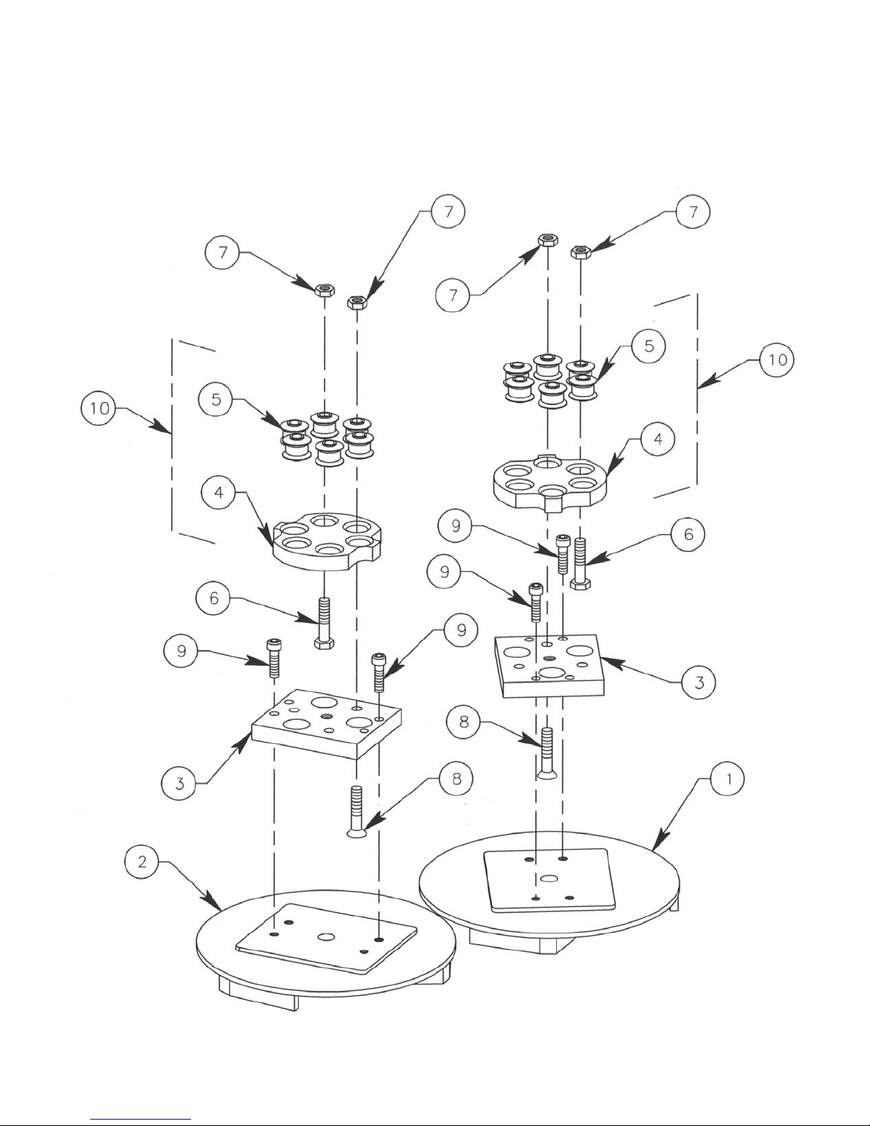
SG24 GRINDER FORM GOM3259601, VERSION 1.2, AUTHORIZATION: DVR, PAGE: 58
Multi-Accessory Disc Assembly
SG24 Series Surface Grinders
Page 61

SG24 GRINDER FORM GOM3259601, VERSION 1.2, AUTHORIZATION: DVR, PAGE: 59
Reference
Number
PART
NUMBER
DESCRIPTION QTY
1
2
3
4
5
6
7
8
9
10
SG24-0140
SG24-0150
SG24-0130
SG24-0120
J-6250-2
15071600
53070000
27071800
60061200
SG24-0120-A
Disc, Multi-Accessory, LH
Disc, Multi-Accessory, RH
Bar, Mounting
Disc, Mounting
Mount, Rubber, Lord® Type
Screw, Cap, 7/16-14 UNC x 2”, Plated, Grade 5
Nut, Hexagon, Locking, 7/16-14 UNC, Plated
Screw, Countersunk, 7/16-14 UNC x 2-1/4”
Screw, Socket, 3/8-16 UNC x 1-1/2”, Plated
Disc. Mounting Assembly
(Included Qty 6 of J-6250-2 and Qty 1 of SG24-0120)
1
1
2
2
12
6
12
6
8
2
Multi-Accessory Disc Assembly
SG24 Series Surface Grinders
Page 62

SG24 GRINDER FORM GOM3259601, VERSION 1.2, AUTHORIZATION: DVR, PAGE: 60
Axle Cradle Assembly
SG24 Series Surface Grinder
Page 63

SG24 GRINDER FORM GOM3259601, VERSION 1.2, AUTHORIZATION: DVR, PAGE: 61
Reference
Number
PART
NUMBER
DESCRIPTION QTY
1
2
3
4
5
6
7
8
9
10
11
12
SG24-0190
SG24-0260
SG24-0200
20031200
17120000
18100000
17100000
FF-838-1
62121200
17080000
16080000
15081000
Arm, Swing
Wheel
Axle, Plated
Pin, Roll, 3/16” x 1-1/2”
Washer, Flat, 3/4”, Plated
Nut, Hexagon, 5/8-11 UNC, Plated
Washer, Flat, 5/8”, Plated
Bearing, Oilite®
Bolt, Shoulder, 3/4-10 UNC x 1-1/2”
Washer, Flat, 1/2”, Plated
Washer, Lock, 1/2”, Plated
Screw, Cap, 1/2-13 UNC x 1-1/4”, Plated
2
2
1
4
2
2
2
2
2
2
2
2
Axle Cradle Assembly
SG24 Series Surface Grinder
Page 64

SG24 GRINDER FORM GOM3259601, VERSION 1.2, AUTHORIZATION: DVR, PAGE: 62
Operator Handle Assembly
SG24/G Series Surface Grinder
[Equipped With Gasoline Engine]
Page 65

SG24 GRINDER FORM GOM3259601, VERSION 1.2, AUTHORIZATION: DVR, PAGE: 63
Reference
Number
PART
NUMBER
DESCRIPTION QTY
1
2
3
4
5
6
7
8
9
10
11
12
13
SG24-0160
SG24-0170
34030500
15081200
18080000
53030001
17080000
16080000
SG24-0170-020
SG24-0170-030
SG24-5020
SG24-5040
KIC-172
Handle, Operator
Lever, Throttle Control, With Cable and Knob
Screw, Socket, #10-32 UNF x 5/8”, Plated
Screw, Cap, 1/2-13 UNC x 1-1/2”, Plated, Grade 5
Nut, Hexagon, 1/2-13 UNC, Plated
Nut, Hexagon, Nylock®, #10-32 UNF, Plated
Washer, Flat, 1/2”, Plated
Washer, Lock, 1/2”, Plated
Cable, Throttle, Complete
Knob, Throttle, Control
Decal, Throttle
Sign, Quik-Tips
Ring, Kick-Out
1
1
2
2
2
2
4
4
1
1
1
1
2
Handle Assembly
SG24/G Series Surface Grinder
[Equipped With Gasoline Engine]
Page 66

SG24 GRINDER FORM GOM3259601, VERSION 1.2, AUTHORIZATION: DVR, PAGE: 64
Engine Mounting Assembly
SG24/G Series Surface Grinder
[Equipped With Gasoline Engine]
Page 67

SG24 GRINDER FORM GOM3259601, VERSION 1.2, AUTHORIZATION: DVR, PAGE: 65
Reference
Number
PART
NUMBER
DESCRIPTION QTY
1
2
3
4
5
6
7
8
9
10
11
12
13
14
15
16
17
18
19
20
GXV340
SG24-0110
SG24-0320
SG24-0315
SG24-0300
63042000
31050500
17070000
16070000
15071200
15051400
17050000
16050000
18050000
15050801
18060000
17060000
CS8-0470
16060000
SG24-0317
Engine, Honda
Mount, Gasoline Engine
Clutch, Centrifugal, With Pulley, Complete
Adapter, M20 x 7/8-14 UNF
Cap, 37° Flare, Female, Drilled
Key, Square, 1/4” x 1/4” x 2-1/2”
Screw, Set, Cup Point, 5/16-18 UNC x 5/16”
Washer, Flat, 7/16”, Plated
Washer, Lock, 7/16”, Plated
Screw, Cap, 7/16-14 UNC x 1-1/2”, Plated, Grade 5
Screw, Cap, 5/16-18 UNC x 1-3/4”, Plated, Grade 5
Washer, Flat, 5/16”, Plated
Washer, Lock, 5/16”, Plated
Nut, Hexagon, 5/16-18 UNC, Plated
Screw, Cap, 5/16-24 UNF x 1”, Plated, Grade 5
Nut, Hexagon, 3/8-16 UNC, Plated
Washer, Flat, 3/8”, Plated
Screw, Cap, 3/8-16 UNC x 3-1/2”, Full Thread, Plated
Washer, Lock, 3/8”, Plated
Seal, Adapter
1
1
1
1
1
1
2
1
1
1
2
2
3
2
2
6
6
2
4
1
Engine Mounting Assembly
SG24/G Series Surface Grinder
[Equipped With Gasoline Engine]
Page 68

SG24 GRINDER FORM GOM3259601, VERSION 1.2, AUTHORIZATION: DVR, PAGE: 66
Operator Handle Assembly
SG24/E And SG24/E3HP Series Surface Grinders
[Equipped With Electric Motor]
Page 69

SG24 GRINDER FORM GOM3259601, VERSION 1.2, AUTHORIZATION: DVR, PAGE: 67
Reference
Number
PART
NUMBER
DESCRIPTION QTY
1
2
3
4
5
6
7
8
9
10
11
12
13
14
15
16
17
18
19
20
21
22
23
24
25
26
SG24-0160
HUB-1390
SP8/E-0100
SG24-0090
HUB-2321
SG24/E3HP-0020
CG-5050
CWV-1007
37030400
16040000
18040000
16030000
18030000
15040400
17080000
16080000
18080000
15081200
801
HUB-1222
SG24/E3HP-0450
SG24/E3HP-0460
HUB-2323
SG24/E3HP-0010
53030000
60030500
SG24-0390
86060000
SG24/E-5040
KIC-172
Handle, Operator
Housing, Switch (Used On SG24/E only)
Cable
Cable
Plug, Male (2 hp Motor Only)
Plug, Male (3 hp Motor Only)
Relief, Strain (Used On SG24/E only)
Clamp, Cable
Screw, Pan Head, #10-32 UNF x 1/2”, Plated
Washer, Lock, 1/4”, Plated
Nut, Hexagon, 1/4-20 UNC, Plated
Washer, Lock, Number 10, Plated
Nut, Hexagon, 10-32 UNF, Plated
Screw, Cap, 1/4-20 UNC x 1/2”, Plated, Grade 5
Washer, Flat, 1/2”, Plated
Washer, Lock, 1/2”, Plated
Nut, hexagon, 1/2-13 UNC, Plated
Screw, Cap, 1/2-13 UNC x 1-1/2”, Plated, Grade 5
Nut, Bulkhead (Included With Reference Number 6)
(Used On SG24/E only)
Switch
(Used On SG24/E)
(Used On SG24/E3HP50 only)
(Used On SG24/EHP60 only)
Receptacle, Female
(Used On SG24/E only)
(Used On SG24/E3HP50 and SG24/E3HP60)
Nut, Hexagon, Nylock®, #10-24 UNC, Plated
(Used On SG24/E3HP50 and SG24/E3HP60)
Screw, Socket Head, #10-24 UNC, Plated
(Used On SG24/E3HP50 and SG24/E3HP60)
Guard, Switch
Nut, Hexagon, Flange, 3/8-16 UNC, Plated
Sign, Quik-Tips
Ring, Kick-Out
1
1
1
1
1
1
2
2
2
2
2
2
2
2
4
4
2
2
Ref.
1
1
1
1
1
2
2
1
4
1
2
Operator Handle Assembly
SG24/E And SG24/E3HP Series Surface Grinders
[Equipped With Electric Motor]
Page 70

SG24 GRINDER FORM GOM3259601, VERSION 1.2, AUTHORIZATION: DVR, PAGE: 68
Electric Motor Mounting Assembly
SG24/E And SG24/E3HP
Series Surface Grinder
[Equipped With Electric Motor]
Page 71

SG24 GRINDER FORM GOM3259601, VERSION 1.2, AUTHORIZATION: DVR, PAGE: 69
Reference
Number
PART
NUMBER
DESCRIPTION QTY
1
2
3
4
5
6
7
8
9
10
11
12
13
14
15
16
17
18
SG24-0250
121173.00
121360.00
SG24-0500
SG24-0510
63031600
CG-3150
15050800
17050000
16050000
18050000
CS8-0470
31050500
801
17060000
16060000
18060000
002922
SP8-5070
SP8/E5HP-5020
Mount, Electric, Motor
Motor, Electric, 2 HP, 115/230 VAC
(Used On SG24/E Only)
Motor, Electric, 3 HP, 230 VAC, 50/60 HZ
(Used On SG24/E3HP50 and SG24/E3HP60 Only)
Pulley
(Used On SG24/E & SG24/E3HP 60 HZ Only)
Pulley
(Used On SG24/E3HP 50 HZ Only)
Key, Square, 3/16” x 3/16” x 2”
Relief, Strain
Screw, Cap, 5/16-18 UNC x 1”, Plated
Washer, Flat, 5/16”, Plated
Washer, Lock, 5/16”, Plated
Nut, Hexagon, 5/16-18 UNC, Plated
Screw, Cap, 3/8-16 UNC x 3-1/2, Full Thread, Plated
Screw, Set, Cup Point, 5/16-18 UNC x 5/16”
Nut, Bulkhead (Included With Reference Number 6)
Washer, Flat, 3/8”, Plated
Washer, Lock, 3/8”, Plated
Nut, Hexagon, 3/8-16 UNC, Plated
Switch, Toggle, 115/230 VAC Selection
(Used On SG24/E Only)
Decal, Warning (Used On SG24/E Only)
Decal, Warning
(Used On SG24/E3HP50 and SG24/E3HP60 Only)
1
1
1
1
1
1
1
6
6
6
6
2
1
Ref.
6
4
6
1
1
1
Electric Motor Mounting Assembly
SG24/E And SG24/E3HP
Series Surface Grinder
[Equipped With Electric Motor]
Page 72

SG24 GRINDER FORM GOM3259601, VERSION 1.2, AUTHORIZATION: DVR, PAGE: 70
Propane Conversion Assembly
SG24/GHP Series Surface Grinder
[Equipped With Propane Converted Engine]
Page 73

SG24 GRINDER FORM GOM3259601, VERSION 1.2, AUTHORIZATION: DVR, PAGE: 71
Reference
Number
PART
NUMBER
DESCRIPTION QTY
1
2
3
4
5
6
7
8
9
10
11
12
13
14
15
16
17
18
19
20
21
22
23
24
25
26
27
28
29
30
31
5550
TB-4
SG24-0210
SG24-0290
7141M
7141F
149F-6-4
4401-6S
FC321-06
3865
HC8346
15040500
VFF30-2-4
17060000
TB-2-60
16060000
18060000
36060800
SB-200-26
56100000
33SB
AF4-66
11SB
2247-4-4S
501-123
T60-G
506-009
2F-256
2F-158
650-002
SG24-5060
Cylinder, Propane
Bracket, Mounting, Propane Cylinder
Cover, V-Belt
Bracket, Mounting, Propane Valves
Adapter
Connecter
Fitting, 90°
Fitting, HP Straight
Hose
Valve, Relief
Fitting
Screw, Cap, 1/4-20 UNC x 5/8”, Plated, Grade 5
Fuelock, Filter, Vacuum
Washer, Flat, 3/8”, Plated
Toggle
Washer, Lock 3/8”, Plated
Nut, Hexagon, 3/8-16 UNC, Plated
Screw, Truss Head, 3/8-16 UNC x 1”, Plated
Grommet
Clamp, Hose, 5/8”
Nipple, Hose
Backcheck, Vacuum
Nipple, Hose
Elbow
Hose, Fuel
Regulator, Fuel
Hose, Vacuum
Spud
Fitting
Cap, Vacuum
Decal, Propane Starting Instruction
1
1
1
1
1
1
2
1
1
1
1
4
1
2
1
6
6
4
1
2
1
1
1
1
1
1
1
1
1
2
1
Propane Conversion Assembly
SG24/GHP Series Surface Grinder
[Equipped With Propane Converted Engine]
Page 74
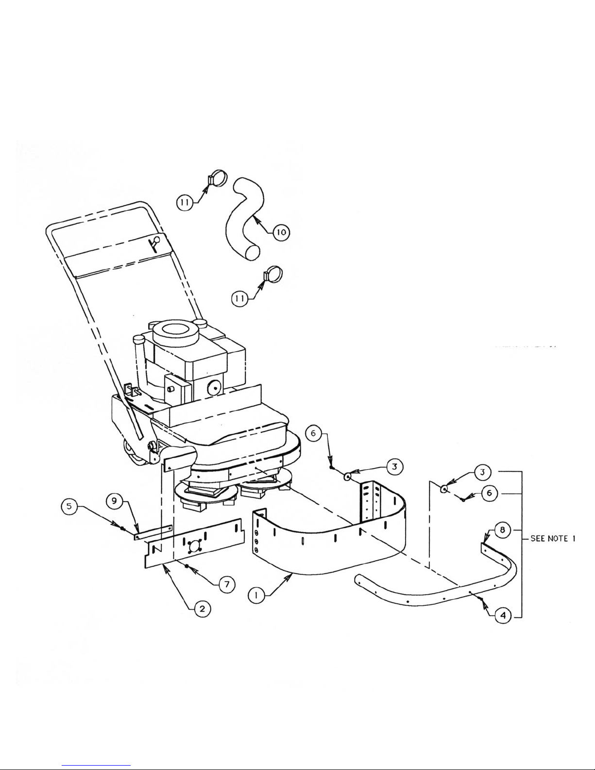
SG24 GRINDER FORM GOM3259601, VERSION 1.2, AUTHORIZATION: DVR, PAGE: 72
Replacement Parts Diagram/Installation
Safety And Dust Shield Assembly
SG24 Series Surface Grinder
Page 75

SG24 GRINDER FORM GOM3259601, VERSION 1.2, AUTHORIZATION: DVR, PAGE: 73
Reference
Number
PART
NUMBER
DESCRIPTION QTY
1
2
3
4
5
6
7
8
9
10
11
SG24-0230
SG24-0350
49040000
27040800
15050700
15040700
53050000
SG24-0220
SG24-0370
SG24-0380
56480000
Skirt, Grinder
Skirt, Assembly
Washer, Fender 1/4”
Screw, Countersunk 1/4-20 UNC x 1”, Plated
Screw, CAP 5/16-18 UNC x 7/8”, Plated
Screw, CAP 1/4-20 UNC x 7/8”, Plated
Nut, Hex 5/16-18 UNC, Nylock®, Plated
Bumper, Rubber
Strap, Support
Hose, Vacuum
Clamp, Hose
1
1
2
9
4
2
4
1
2
1
2
Replacement Parts Diagram/Installation
Safety And Dust Shield Assembly
SG24 Series Surface Grinder
NOTE:
1) Optional installation: Install Skirt (item 1) with either (9) countersunk cap screws (item 4) and reinstall
Bumper (item 8) or with (9) washers (item 3) and (9) hex head cap screws (item 6)
2) Install Hose (item 10) to 3” OD tube welded to Grinder and to tube on Skirt (item 2) with hose clamps
(items 11)
Page 76
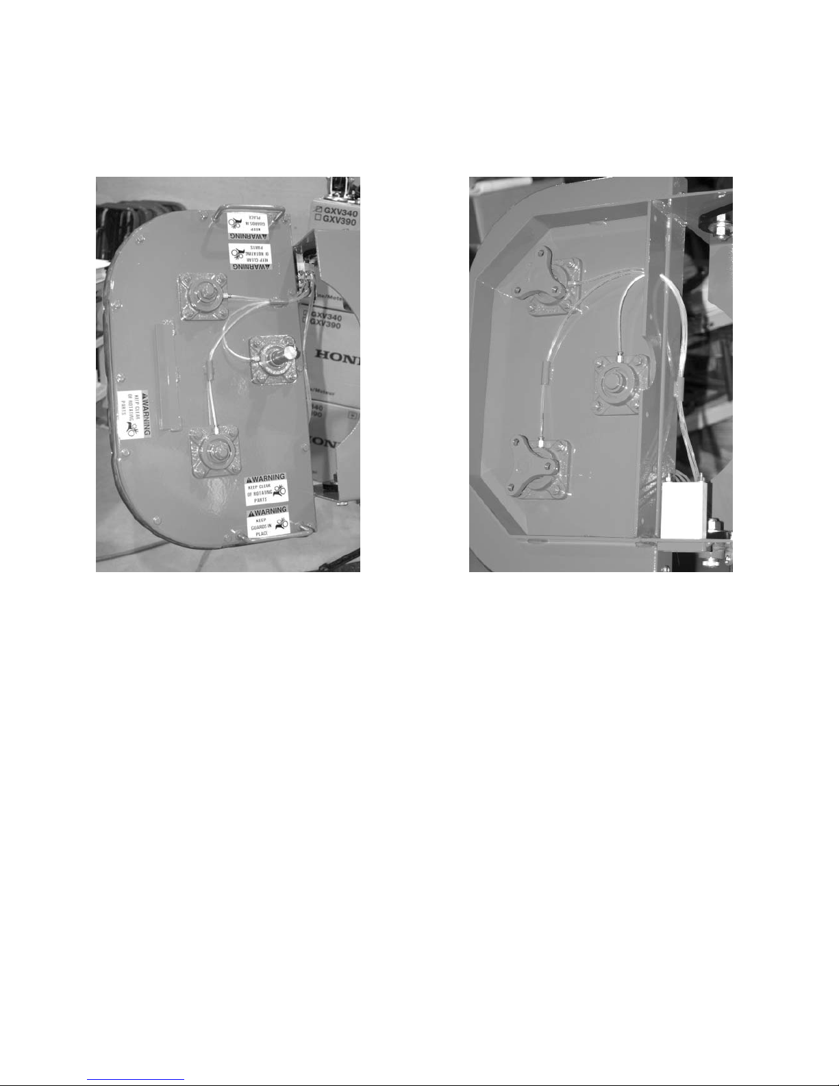
SG24 GRINDER FORM GOM3259601, VERSION 1.2, AUTHORIZATION: DVR, PAGE: 74
Lubrication Diagram
SG24 Series Surface Grinder
Top of the SG24
Dual head Surface Grinder
Bottom of the SG24
Dual head Surface Grinder
Page 77
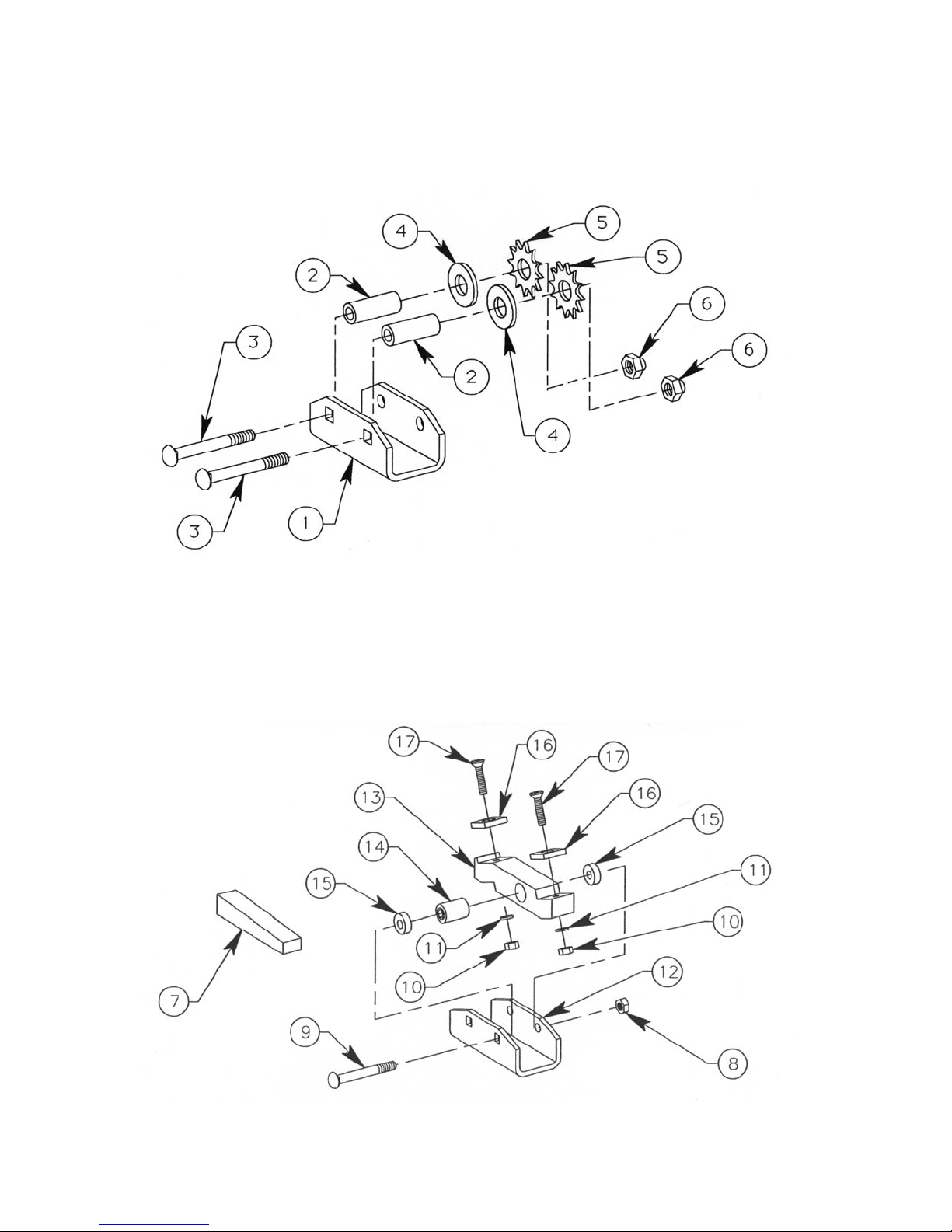
SG24 GRINDER FORM GOM3259601, VERSION 1.2, AUTHORIZATION: DVR, PAGE: 75
Cutter Assembly SCRAPE-R-TACH
®
Coating Removal System
SG24 Series Surface Grinders
Scarifier Assembly
SG24 Series Surface Grinders
Page 78

SG24 GRINDER FORM GOM3259601, VERSION 1.2, AUTHORIZATION: DVR, PAGE: 76
Cutter Assembly SCRAPE-R-TACH
®
Coating Removal System
SG24 Series Surface Grinders
Reference
Number
PART
NUMBER
DESCRIPTION QTY
7
8
9
10
11
12
13
14
15
16
17
SG24-1800
53050000
87052000
18040000
16040000
SG24-1900-010
SG24-1900-020
J-2005-2
SG24-1900-040
SG24-1900-030
27041000
Wedge, Plastic
Nut, Hexagon, 5/16-18 UNC, Nylock
®
, Plated
Bolt, Carriage, 5/16-18 UNC x 2-1/2”, Plated, Grade 5
Net, Hexagon, 1/4-20 UNC, Plated
Washer, Lock, 1/4, Plated
Housing
Holder, Insert
Mount, Rubber
Spacer
Insert, Tungsten Carbide
Screw, Countersunk, 1/4-20 UNC x 1-1/4”
1
1
1
2
2
1
1
1
2
2
2
Scarifier Assembly
SG24 Series Surface Grinders
Reference
Number
PART
NUMBER
DESCRIPTION QTY
1
2
3
4
5
6
7
SG24-1900-012
SG24-1600-020
87052000
SG24-4000
SP8-3000
SP8-3100
SP8-3200
53050000
SG24-1800
Housing
Bushing
Bolt, carriage, 5/16-18 UNC x 2 1/2” UNC, Plated, Grade 5
Washer, Flat, 5/8”, Heat Treated, Plated
Flail, Star, Heat Treated Steel
Flail, Beam, Heat Treated Steel
Flail, Pentagonal, Carbide Tipped
Nut, Hexagon, 5/16-18 UNC, Nylock
®
, Plated
Wedge, Plastic
*QTY(12) Required with SP8-3000 and SP8-3100, Flails
*QTY(8) Required with SP8-3200 Flails
**QTY(12) Required with SP8-3000 and SP8-3100, Flails
**QTY(8) Required with SP8-3200 Flails
1
2
2
*
**
**
**
2
1
Page 79
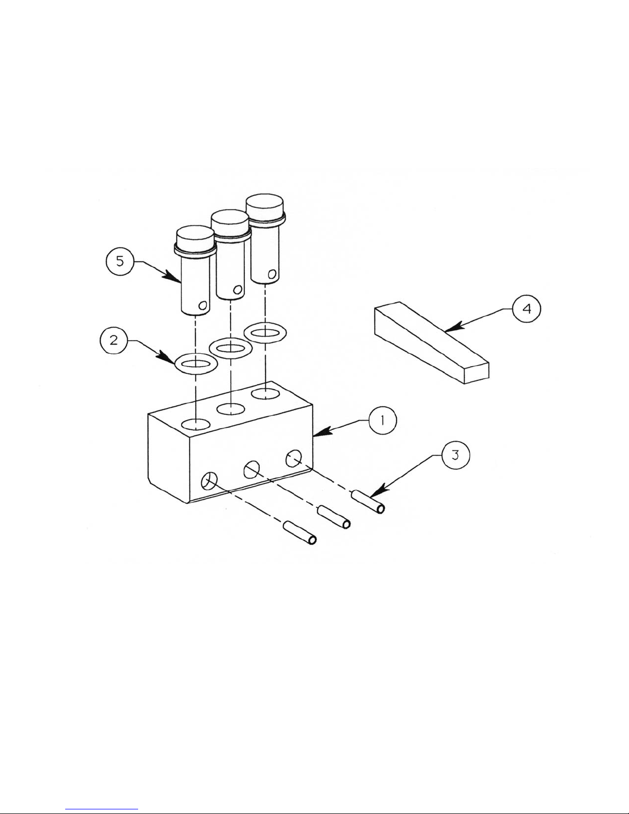
SG24 GRINDER FORM GOM3259601, VERSION 1.2, AUTHORIZATION: DVR, PAGE: 77
Grinding Block Assembly DIAM-A-TACH
®
Diamond Grinding System
SG24 Series Surface Grinders
Page 80

SG24 GRINDER FORM GOM3259601, VERSION 1.2, AUTHORIZATION: DVR, PAGE: 78
Reference
Number
PART
NUMBER
DESCRIPTION QTY
1
2
3
4
5
SG24-2101-010
SG24-2101-030
83040901
SG24-1800
SG24-2100-020
SG24-2101-020
SG24-2102-020
SG24-2103-020
SG24-2104-020
Block
“O” Ring
Pin, Retaining (Stainless Steel)
Wedge, Plastic
Pin, Diamond, Purple Identification Color
(40-50 Grit, For Aggress Grinding Use)
Pin, Diamond, Yellow Identification Color
(40-50 Grit, For General Purpose Use)
Pin, Diamond, Black Identification Color
(40-50 Grit, For Epoxy Morta and Ashpalt Use)
Pin, Diamond, Green Identification Color
(40-50 Grit, For Green Conrete And Asphalt Use)
Pin, Diamond, Red Identification Color
(40-50 Grit, For Final Grinding/Polishing Use)
1
3
3
1
3
3
3
3
3
Grinding Block Assembly DIAM-A-TACH
®
Diamond Grinding System
SG24 Series Surface Grinders
 Loading...