

Page 1
OPERATOR'S GUIDE
FOOD CHOPPER
MODELS: SD-50, MC-50, MC-100, SD112, MC112
CONTENTS
Safety ............................................................... 2 Attachments .................................................……….. 10
General Description.......................................... 3 Troubleshooting ………............................................. 11
Unpacking and Assembly................................. 4 Lubrication and Maintenance ....................…………. 12
Cleaning ........................................................... 5 Parts Replacement and Service ...................………. 12
Electrical Requirements ................................... 8 Replacement Parts ......…............................………… 13
Operation ........……...….................................... 9
10 16.96
Page 2

SAFETY
RECOGNIZE SAFETY INFORMATION. When you see this
symbol on your machine or in this manual, be alert to the
potential for personal injury,
Follow the recommended precautions and safe operating
practices.
UNDERSTAND SIGNAL WORDS. DANGER, WARNI NG
and CAUTION appear with the safety -alert symbol in this
manual and on safety labels on the machine to identify the
level of hazard seriousness.
DANGER indicates a hazard that WILL result in severe
personal injury or death.
WARNING indicates a hazard or unsafe practice which
COULD result in severe personal injury or death.
CAUTION indicates hazards or unsafe practices which
COULD result in minor personal injury or equipment
damage.
READ ALL INSTRUCTIONS
Read this operator's manual before using the m achine.
Failure to follow the instructions provided could result in
personal injury or equipment damage.
KEEP OUT OF REACH OF CHILDREN
This chopper is intended for commercial use only.
Operators must be 18 years of age or older.
DO NOT FEED FOOD BY HAND.
Always use the foodpusher.
Always place the product to be ground on the tray.
DO NOT OPERATE IF DAMAGED
Do not operate this chopper with a damaged cord or plug, or
if the chopper has been dropped or damaged in any
manner. Contact the nearest factory -authorized service
center for examination, repair or adjustment. (Refer to the
service center list included in the Owner's Information
Packet.)
Do not allow the cord to touch hot surfaces.
Do not allow the cord to hang over the edge of a table or
counter.
Do not allow the cord near cutting board.
DO NOT LEAVE CHOPPER UNATTENDED.
UNPLUG CHOPPER
Set the switch to OFF and unplug the chopper from the
outlet when not in use and before cleaning or removing
jams.
KEEP MACHINE AWAY FROM WATER
Do not let machine base stand in water.
Do not immerse the chopper in water or any other liquid.
ATTACHMENTS
Do not use attachments not recommended by the
manufacturer.
Follow the manufacturer's instructions for use of
attachments.
SAVE THESE INSTRUCTIONS.
Keep this booklet in a convenient location for future
reference.
2
01.15.96
Page 3
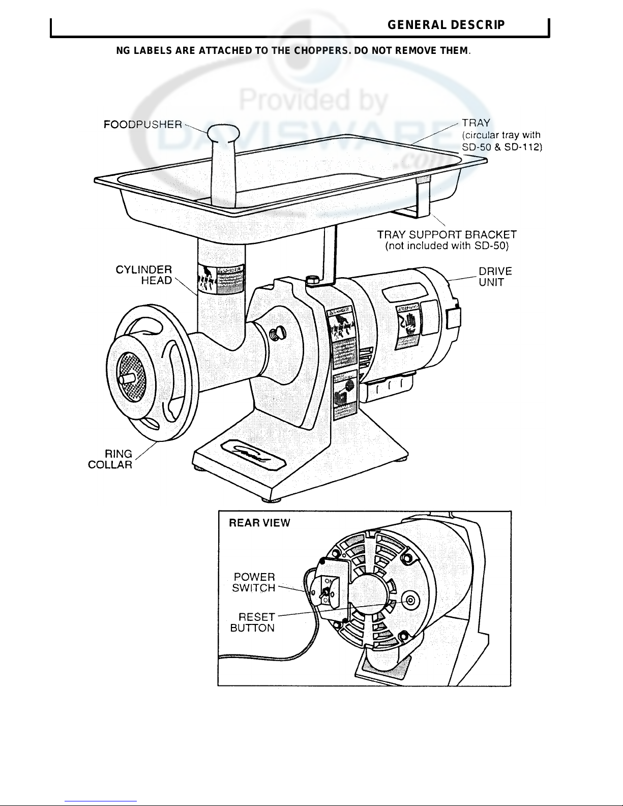
GENERAL DESCRIPTION
THESE WARNING LABELS ARE ATTACHED TO THE CHOPPERS. DO NOT REMOVE THEM .
3
01 15.96
Page 4

UNPACKING AND ASSEMBLY
the body by turning the bolt counter
-
clockwise.
UNPACKING
Inspect the shipping carton and its contents for shipping damage. If
you detect shipping damage to any of the contents of the carton,
notify your carrier.
The chopper is shipped in four parts: (1) chopper drive unit,
(2) cylinder head assembly, (3) tray, (4) tray support
bracket.
NOTE: Model SD-50 does not require a tray support bracket.
1. Open the carton and take out the tray, the tray support
bracket and the foodpusher.
2. Remove the foam insert, and take out the cylinder head and
the chopper drive unit.
If there are any parts missing notify us immediately at 1-800-251-
4232.
The chopper should be thoroughly cleaned and sanitized before
using to ensure sanitary conditions. (See Cleaning Sect ion.)
ASSEMBLY
CAUTION: The chopper should be installed
on a level counter top strong enough to safely
support its weight.
Tray Support Bracket
1. Remove the tray support bolt and lockwasher from the top of
2. Place the tray support bracket over the hole in the top of the
chopper (with the bracket top towards the back of the motor).
3. Replace the lockwasher and support bolt and tighten by turning
the bolt clockwise with an adjustable wrench.
4
01,1596
Page 5

DISASSEMB
LY FOR CLEANING
Clean and sanitize the chopper before using the first time. after each
use, and before grinding different types of food products. Follow
company, local and state health/sanitation codes.
WARNING: Set the power switch to OFF, and unplug the
chopper before cleaning or handling.
Do NOT use caustic or abrasive cleaners.
Do NOT spray cleaning materials or water toward the switch case,
reset button, or motor cooling opening
Remove the tray by lifting upward.
CLEANING
Cylinder Head Assembly
1. Loosen the ring collar by turning a quarter turn counter-clockwise.
2. Loosen the thumbscrew by turning three turns counter-clockwise.
3. Remove the cylinder head by pulling it forward.
4. Loosen the ring collar by turning three turns counter-clockwise.
5. Push the feedscrew shaft forward into the cylinder head.
5
Page 6

1. Wash all surfaces and parts of the cylinder head assembly with
CLEANING ... continued
6. Unscrew and remove the ring collar.
7. Remove the cutter plate, knife and feedscrew.
WASH ALL SURFACES
hot, soapy water and a clean cloth. Dry thoroughly.
NOTE: Do not let the feedscrew soak in water, as this would damage the
fiber material in the fiber washer on the feedscrew.
2. Wash the tray in hot, soapy water with a clean cloth.
3. Wipe the tray bracket, body and motor with a clean, moist cloth.
Dry thoroughly.
4. Lightly coat the feed screw, cutter plate, knife, and inside the
cylinder head and ring collar with a light non-toxic mineral oil.
REASSEMBLY
Cylinder Head Assembly
1. Insert the cylinder head into the front cover, seating the pin into
the hole in the cover.
2. Lock in place by turning the thumbscrew clockwise until tight.
3. Insert the feedscrew into the cylinder, being sure that the square
on the feedscrew is fully seated in the square opening in the
output gear.
NOTE: Be sure fiber washer is in place. (See Maintenance Sec tion.)
6
Page 7

4. Place the knife over the feedscrew stud, being sure that the
it clockwise.
square opening in the knife is fully seated in the feedscrew stud.
NOTE: The sharp edge of the knife MUST FACE OUTWARD.
5. Place the cutter plate onto the feedscrew stud in front of the
knife, being sure the groove in the plate fits over the pin in the
cylinder head.
6. Place the ring collar on the cylinder head, tightening it by turning
CLEANING …. continued
NOTE: Do not overtighten the ring collar. Binding or excessive wear to
the internal parts will occur if the ring collar is too tight.
7. Place the tray on the tray support bracket with the spout seated
in the cylinder head.
7
Page 8

ELECTRICAL REQUIREMENTS
Plug the processor into a properly grounded three-prong outlet. DO NOT
use an extension cord.
Use a 115 Volt, A.C., 60 Hz power source, as indicated on the Data Plate
on the back of the unit. To operate the unit on other voltages, the
processor must be returned to the factory for modification.
All electrical connections must be made in compliance with all applicable
local electrical codes, as well as the latest edition of the National
Electrical Code (NFPA 70).
OPERATION
CUTTER PLATE SELECTION
Standard cutter plate
The chopper is equipped with a general purpose 3/16" hole size cutter
plate, recommended for grinding meat, poultry and fish products for a
medium coarse texture.
NOTE: A finer texture may be achieved by grinding the product a
second time using the same cutter plate.
Other cutter plates available
1/8": Second grinding of meat, poultry and fish products for a fine
texture.
3/16": General purpose (See above description.).
5/16": Second grinding of meat , poultry and fish products for a very
coarse texture.
3/8": First grinding of meat, poultry and fish products.
1/2", 5/8" and 3/4": Fruit and vegetable grinding (tomatoes,
salsa, relishes, etc).
NOTE: For the most efficient use of the chopper, use the appropriate cutter plate for the application.
Cutter plate and spare parts information are on Pages 13-15.
Clean and sanitize the chopper before using the first time, after each use, and before grinding different
types of food products. Follow company, local and state health/sanitation codes.
8
Page 9

fine texture, replace the cutter plate with a smaller hole size for the
OPERATION
CAUTION: Do not grind products that contain bone.
Be sure tray is in place before operating chopper.
1. Remove any bone and excess gristle from meat, poultry and fish
products; cut product to be ground into pieces no larger than 2".
and place them on the tray.
2. Plug the power cord into a grounded three-prong outlet (See
Electrical Requirements, Page 8.), and set the power switch to
ON.
OPERATION . . . continued
DANGER: Always use the foodpusher. Do not feed food by
hand or with any other utensil.
4. Using the foodpusher, feed pieces into the cylinder head.
If the product requires a finer texture, repeat the process. For a very
second grinding.
5. Set the power switch to OFF and unplug cord.
Clean the chopper after each operation (See Cleaning Section.).
9
Page 10

ATTACHMENTS
SAUSAGE TUBE
Operation
1. Grind the sausage product to the desired texture (The general
purpose 3/16" cutter plate is recommended. See Operation
Section.)
2. Add desired seasonings to the ground product and mix
thoroughly.
3. Remove the ring collar, cutter plate and knife. Reinstall the cutter
plate. (Do not reinstall the knife.)
4. Place the sausage tube in the ring collar and place the ring collar
on the cylinder head and tighten.
5. Rub a small amount of vegetable oil on the tube.
NOTE: When sausage casings are used they must first be properly cleaned.
Fill the sausage casings as follows:
1. Tie a knot in one end of a desired length of casing. Slide the other
end over the tube, pushing the entire length of the casing onto the
tube.
10
Page 11

NOTE: Be sure that meat is firmly packed into the cylinder head. Air
spaces will result in air bubbles in the sausage links.
2. Using the foodpusher, feed the sausage product into the cylinder
head, easing off the casing as it fills, taking care not to overfill.
3. Tie a knot in the finished end of the filled casing. Pinch and twist
the sausage into links.
TROUBLESHOOTING
WARNING: Set the power switch to OFF, and unplug
the machine before attempting to disassemble any part
of the chopper for troubleshooting.
Motor strains when starting:
The ring collar may be too tight.
Loosen the ring collar.
Meat does not feed easily through the cylinder head:
The pieces are too large.
Cut the product to be ground into smaller pieces.
ATTACHMENTS . . . continued
Excess juices build up in head when chopping fish, fruits,
vegetables or other watery products:
The drain hole in the bottom of the head is clogged.
Set the power switch to OFF and unplug the machine. Remove the
cylinder head, disassemble and clean out the drain hole.
Reassemble, plug in the machine, set the power switch to ON, and
continue processing the product.
Motor stalls or stops while operating
The cylinder head has blockage due to bone or excessive gristle
and the motor is overloaded.
Your chopper is equipped with a manual reset thermal overload
protection device. Should overloading of the motor occur, the overload
device shuts the motor off. Set the power switch to OFF, unplug the
machine, dissassemble the cylinder head, and remove excess gristle.
Reassemble. To reset the overload device, push the red manual reset
button (located on the rear of the motor), and plug the machine in.
Set the power switch to ON, and continue processing the product. If
gristle continues to block the cylinder head, use a larger hole size
cutter plate.
11
Page 12

TROUBLESHOOTING ... continued
Meat appears to be stringy:
Knife and/or cutter plate may be dull.
Replace with a new knife and cutter plate.
Meat appears to be mushy:
The ring collar may be too tight.
Loosen the ring collar.
NOTE: If meat has a watery texture, and the resulting product appears
mushy, cut the product into smaller pieces.
The cutter plate hole size is too small.
Set the power switch to OFF, unplug the machine, disassemble,
and remove the cutter plate. Reassemble, using a larger hole
size cutter plate. Set the power switch to ON, and continue
processing the product.
LUBRICATION AND MAINTAINENCE
LUBRICATION
This unit has been permanently lubricated. Do not add oil or grease.
MAINTENANCE
1. After prolonged use, the knife and cutter plates may become dull
and should be replaced. (See Troubleshooting Section.)
2. After prolonged use, the fiber washer may become worn and
loose, which could result in damage to the cylinder head
assembly. Remove and replace the fiber washer.
PARTS REPLACEMENT AND SERVICE
PARTS REPLACEMENT
Use the replacement parts list on Pages 13-16 and the parts
distributors list included in the Owner's Information Packet to order
spare parts. Specify the model and serial numbers, part number
and part name.
SERVICE
For repair consult the factory -authorized service center list included in
the Owner's Information Packet for the closest service center.
12
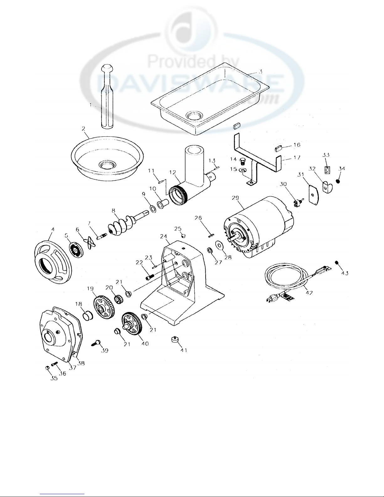
Page 13

REPLACEMENT PARTS PRICE LIST
MODELS: SD-50/MC-50/SD112/MC-112
**
**
**
**
**
**
**
6
7
8
9
10
11
12
**
13
14
15
16
17
18
19
20
21
22
23
24
*
25
26
27
28
Effective: October
1,1997
(Replacing Models: SD-33/MC-33/MC-40/MC-75)
QTY. LIST
KEY
NO. PART NO. NAME: DESCRIPTION MACH. EACH
PER PRICE
QTY. LIST
KEY
NO. PART NO. NAME: DESCRIPTION MACH. EACH
PER PRICE
1 06-MC-1010 FOODPUSHER ……..................................... 1
2 30-MC-6043 TRAY:ALUMINUM, CIRCULAR ............... 1
3 04-MC-6042 TRAY.-SS, #12 CHOPPERS.....……............. 1
4 30-MC-1003 RING COLLAR:#12...................…............... 1 75.00
5 09-MC-5062 PLATE:3/16, #12 ......................……............. 1
OPTIONAL CUTTER PLATES
09-MC-5061 PLATE:1/8, #12 .........................……............ 1
09-MC-5063 PLATE:1/4, #12 ..........................…............... 1
09-MC-5064 PLATE:5/16, #12 ........................…............... 1
09-MC-5065 PLATE:3/8, #12 …......................................... 1
09-MC-5067 PLATE:1/2, #12 ..........…............................... 1
09-MC-5068 PLATE:5/8, #12 .......................….................. 1
09-MC-5069 PLATE:3/4, #12 ............…............................. 1
09-MC-514 KNIFE:#12............................…...................... 1 19. 00
08-MC-732 STUD:FEEDSCREW, #12 .......…….............. 1 9.00
30-MC-6023 FEEDSCREW ASSY:#12..........…................. 1 118.00
(INC:7&8)
06-MC-869 FIBER WASHER:#12..............…................... 1 1.00
08-MC-535 BUSHING:THRUST HEAD, #12 ....…......... 1 9.00
08-MC-531 GROOVED PIN:TYPE H 5/32 X 3/4…......... 1 2.00
30-MC-6045 HEAD ASSY:#12.............................….......... 1 243. 00
(INC: 10-13)
30-MC-012B HEAD ASSY COMPLETE:#12........…......... 1 ***
(INC:4-13)
30-12CG-CT COMPLETE CUTTING GROUP:#12 …....... 1
(INC:1,2&4-13)
08-MC-530 GROOVED PIN:TYPE H 5/16 X 3/4.…........ 1 2.00
08-MC-499 SCREW:HXHD 1/2 -13X3/4 ............….......... 1 2.00
08-MC-698 WASHER:LOCK SPLIT, 1/2" .….................. 1 1.00
06-MC-5713 BUMPER.................................……................ 2 2.00
30-MC-498 TRAY SUPPORT BRKT ASSY…. ................ 1 42.00
(INC:16& 17)
08-MC-561 BUSHING:OUTPUT GEAR, #12 COVER….1 9.00
30-MC-6003 OUTPUT GEAR ASSY:#12...................….... 1 81.00
09-MC-6004 MOTOR PINION .................................…...... 1 25.00
08-MC-707 BUSHING:GEARBOX.........................…...... 3 6.00
08-BC-72 SCREW:SCKT HD 3/8 -16 X 1.............…...... 4 1.00
08-MC-4544 GROOVED PIN:TYPE H 3/16 X 7/8....…. .... 2 2.00
30-MC-6000 BASE ASSY........................................…….... 1 355.00
(INC:21,23,24&41)
30-MC-5125 GREASE.................................……................ 1 16.00
06-MC-6012 HOLE PLUG ...........................…....................1 1.00
08-MC-6014 KEY:MOTOR SHAFT..............….................. 1 2.00
06-MC-6029 GASKET:MOTOR SHAFT …...…................ 1 4.00
06-MC-6031 SLINGER:MOTOR SHAFT ......…................. 1 2.00
MOTORS
29 30-MC-6049 MOTOR ASSY:1/2HP, 120V.........…............ 1 459.00
(INC:26-34,42&43)
02-MC-6068 THERMAL PROTECTOR:#CEJ53CB… ...... 1 67.00
*** 02-MC-500 THERMAL PROTECTOR:#CEJ54DB…...... 1 67.00
1/2 HP
*** 02-MC-330 THERMAL PROTECTOR:#CEG51GB…..... 1 67.00
1/3 HP
*** 02-MC-750 THERMAL PROTECTOR:#CEG67GD…..... 1 67.00
3/4 HP
02-MC-6066 CAPACITOR:400-480MF, 120V.........…...... 1 32.00
*** 02-MC-7205 CAPACITOR:161-193MF, 120V.........…...... 1 20.00
1/2 & 1/3 HP
* 08-SM-1219 BEARING:KNIFE PULLEY (6203) .....…..... 2 3.00
* 02-MC-1294 SPRING SET STARTING SWITCH ...…...... 1 2.00
29 30-MC-6010 MOTOR ASSY: 1 HP, 120V.................…..... 1 632.00
(INC:26-34,42 & 43)
02-MC-6069 THERMAL PROTECTOR:#CEJ51CB .….... 1 67.00
02-MC-7500 CAPACITOR:540-648 MF, 120V, 3/4 HP ….1 32.00
* 08-SM-1219 BEARING:KNIFE PULLEY (6203) .......…... 2 37.00
* 02-MC-1294 SPRING SET STARTING SWITCH ....…..... 1 2.00
30 05-6-1501 SWITCH:TOGGLE, 120V.....................…..... 1 16.00
31 02-MC-6067 PLATE:SWITCH MTG. .........................….... 1 13.00
*** 02-MC-6056 HOUSING:SWITCH (CENTURY MOTOR)..1 12.00
32 05-6-4581 GUARD:TOGGLE SWITCH....................…...1 2.00
33 12-6-1779 LABELON/OFF .............................…............ 1 1.00
34 06-6-2192 RUBBER BOOT : TOGGLE SWITCH…....... 1 2.00
35 06-MC-6012 HOLE PLUG ....................................….......... 5 1.00
36 08-MC-584 S CREW:SCKT HD 1/4 -20 X 7/8 SS …......... 5 1.00
37 30-MC-6001 COVER ASSY:#12..........................…........... 1 207.00
(INC:18,21 & 37)
38 06-MC-6011 GASKET:COVER..........................…............ 1 13.00
39 08-MC-519 THUMBSCREW............................…............ 1 13.00
40 30-MC-605A INTERMEDIATE GEAR ASSY .....….......... 1 102.00
41 06-MC-1059 FOOT W/STUD.............................…............. 4 5.00
42 02-MC-5519 CORDSET .....................................……......... 1 18.00
43 02-MC-458 STRAIN RELIEF .............................….......... 1 3.00
* 09-MC-574 SAUSAGE TUBE:#12 ……........................... 1 N/C
* 12-6-1760 LABELCORDSET WARNING..........…........ 1 N/C
* 12-MC-6063 LABELSAFETY (CHOPPERS) ........…........ 1 N/C
* 12-MC-6065 LABELSAFETY (CHOPPERS) ...…............. 1 N/C
* 12-MC-6071 LABELCHOPPER HEAD ASSEMBLY….... 1 N/C
* 12-SM-1755 LABELELECTRICAL WARNING .......….... 1 N/C
* 12-SM-1756 LABELREAD SAFETY INSTRUCTIONS…1 N/C
* Not pictured.
** Refer to current equipment Price List for pricing of these items.
*** Century/Gould motor parts.
_________________________________________________________________________________________________________________________________________________________10.06.97
General Slicing/Red Goat Disposers •1152 Park Ave • P.O.Box 428 •Murfreesboro, Tennessee 37133-0428 •(615)893-4820
Page 14
Page 15

Effective: October
1, 1997
REPLACEMENT PARTS PRICE LIST
**
**
**
**
**
**
**
**
**
**
**
**
**
**
30-MC
-
MODEL: MC-100
QTY. LIST
KEY
PER PRICE
NO. PART NO. NAME: DESCRIPTION MACH. EACH
1 06-MC-1010 FOODPUSHER ......................................………. 1
2 04-MC-6044 TRAY:SS, #22 CHOPPERS....................………. 1
* 30-MC-6043 TRAY:ALUMINUM, CIRCULAR ..............………. 1
3 30-MC-4539 RING COLLAR:#22. ................................……….. 1 97.00
4 09-MC-4542 PLATE:3/16, #22 .....................................………. 1
09-MC-4541 PLATE:1/8, #22 .......................................……… 1
09-MC-4543 PLATE:1/4, #22 .......................................……… 1
09-MC-4544 PLATE:5/16, #22 .....................................……… 1
09-MC-4545 PLATE:3/8, #22 .......................................……… 1
09-MC-4546 PLATE:1/2, #22 .......................................……… 1
09-MC-4547 PLATE:5/8. #22 .......................................……… 1
09-M04548 PLATE:3/4, #22 .......................................……… 1
5 09-MC-4540 KNIFE:#22. ..............................................………. 1
6 08-MC-4543 STUD:FEED SCREW, #22 .....................………. 1 21.00
7 30-MC-4538 FEEDSCREW ASSY:#22........................………. 1 197.00
8 06-MC-4547 FIBER WASHER:#22..............................……….. 1 2.00
9 08-MC-4548 BUSHINQ:THRUST, #22 HEAD .............………. 1 9.00
10 08-MC-4544 GROOVED PIN:TYPEH 3/16X7/8………………. 1 2.00
11 30-MC-6046 HEAD ASSY:#22. ....................................………. 1 342.00
30-MC-022B HEAD ASSY COMPLETE:#22................………. 1
30-22CG-CT COMPLETE CUTTING GROUP:#22 ......……… 1
12 08-MC-4546 GROOVED PIN:TYPEH 3/8X3/4.........…………. 1 2.00
13 06-MC-5713 BUMPER.................................................………. 2 2.00
14 30-MC-6024 TRAY SUPPORT BRKT ASSY...............………. 1 46.00
15 08-MC-499 SCREW:HXHD 1/2-13X3/4 ...................……….. 1 2.00
16 08-MC-698 WASHER:LOCK SPUT, 1/2" ..................………. 1 1.00
17 08-MC-4560 BUSHING:OUTPUT GEAR, #22 COVER ………. 1 13.00
18 30-MC-6017 OUTPUT GEAR ASSY:#22. .........………............ 1 87.00
19 09-MC-6004 MOTOR PINION ..........................………........... 1 25.00
20 08-MC-707 BUSHING:GEARBOX. .................………............ 3 6.00
21 08-BC-72 SCREW:SCKT HD 3/8-16 X 1......………............ 4 1.00
OPTIONAL CUTTER PLATES
(INC:6 & 7)
(INC:9-12)
(INC:3-12)
(INC:1.2A&3-12)
(INC:13&14)
QTY. LIST
KEY
PER PRICE
NO. PART NO. NAME: DESCRIPTION MACH. EACH
22 08-MC-4544 GROOVED PIN:TYPE H 3/16X7/8………… 2 2.00
23 30-MC-6000 BASE ASSY............................................……. 1 355.00
(INC:20,22,23 & 40)
30-MC-5125 GREASE .............................……..................... 1 16.00
24 06-MC-6012 HOLE PLUG ................................……........... 1 1.00
25 08-MC-6014 KEY:MOTOR SHAFT..................…............... 1 2.00
26 06-MC-6029 GASKET:MOTOR SHAFT ..........…............... 1 4.00
27 06-MC-6031 SUNGER:MOTOR SHAFT .........……............ 1 2.00
28 30-MC-6010 MOTOR ASSY: 1 HP, 120V..........…............. 1 632.00
(INC:26-34,42&43)
02-MC-6069 THERMAL PROTECTOR:#CEJ51CB …...... 1 67.00
*** 02-MC-1000 THERMAL PROTECTOR:#CEJ53DD …...... 1 67.00
02-MC-7500 CAPACITOR:540-648 MF, 120V........….........1 32.00
*** 02-MC-7502 CAPACITOR: 189-227 MF, 120V.............….. 1 3.00
08-SM-1219 BEARING:KNIFE PULLEY (6203) ..........…. 2 3..00
02-MC-1294 SPRING SET STARTING SWITCH………... 1 2.00
29 05-6-1501 SWITCH:TOGGLE, 120V........................…... 1 16.00
30 02-MC-6067 PLATE:SWITCH MTG. ............................…... 1 13.00
*** 02-MC-6056 HOUSING:SWITCH (CENTURY MOTOR).. 1 12.00
31 05-6-4581 GUARD:TOGGLE SWITCH....................…... 1 2.00
32 12-6-1779 LABELON/OFF ......................................…… 1 1.00
33 06-6-2192 RUBBER BOOT: TOGGLE SWITCH ......…. 1 2.00
34 06-MC-6012 HOLE PLUG ...........................................…… 5 1.00
35 08-MC-584 SCREW:SCKT HD 1/4 -20 X 7/8 SS………… 5 1.00
36 30-MC-6016 COVER ASSY:#22..................................……. 1 192.00
(INC:17,20&36)
37 06-MC-6011 GASKET:COVER....................................…… 1 13.00
38 08-MC-519 THUMBSCREW......................................…… 1 13.00
39
INTERMEDIATE GEAR ASSY ...............…. 1 102.00
40 06-MC-1059 FOOT W/STUD.......................................…… 4 5.00
41 02-MC-5519 CORDSET ..............................................…… 1 18.00
42 02-MC-458 STRAIN RELIEF .....................................….. 1 3.00
* 09-MC-4580 SAUSAGE TUBE:#22 .............................….. 1 **
* 12-6-1760 LABELCORDSET WARNING................….. 1 N/C
* 12-MC-6063 LABEL-SAFETY (CHOPPERS) ..............…. 1 N/C
* 12-MC-6065 LABELSAFETY(CHOPPERS) ..............…… 1 N/C
* 12-MC-6071 LABEL-CHOPPER HEAD ASSEMBLY...… 1 N/C
* 12-SM-1755 LABELELECTRICAL WARNING ...........… 1 N/C
* 12-SM-1756 LABEL-READ SAFETY INSTRUCTIONS .. 1 N/C
* Not pictured.
** Refer to current equipment Price List for pricing of these items.
*** Call factory for Century/Gould motor parts.
General Slicing/Red Goat Disposers •1152 Park Ave • P.O. Box 428 • Murfreesboro, Tennessee 37133-0428 • (615) 893-4820
10.06.97
Page 16

 Loading...