

Page 1

Elite Steam Residential Steam Humidifiers
User manual
Page 2
We wish to save you time and money!
We can assure you that the thorough reading of this manual will guarantee correct
installation and safe use of the product described
WARNINGS
BEFORE INSTALLING OR HANDLING THE HUMIDIFIER PLEASE CAREFULLY READ AND FOLLOW THE INSTRUCTIONS AND SAFETY STANDARDS
DESCRIBED IN THIS MANUAL AND ON THE LABELS ATTACHED TO THE Elite Steam.
CAUTION: ALWAYS DISCONNECT THE MAIN POWER BEFORE
Elite Steam produces non-pressurized steam by means of electrodes immersed in the water contained in the plastic steam generator cylinder. Electric current
passes through the water between the electrodes, heating the water into steam, which is then used to humidify the air.
The quality of the water used affects the operation of this unit, so the Elite Steam may be supplied with untreated water, as long as this is drinkable and not
softened or demineralized. The water converted into steam is automatically replaced through an electric fill valve. Periodically, based on the water quality ,
the unit will also drain some water to dilute the build-up of minerals in the steam generator and thus extend its life. This humidifier has been designed
exclusively to directly humidify rooms or ducts, using a distribution system. The installation, use and maintenance operations must be carried out according to
the instructions contained in this manual and on the labels applied internally and externally.
IMPORTANT: BEFORE beginning installation:
• Check for shipping damage to cartons. Mark the shipping waybill accordingly.
• Open cartons and check for any hidden damage. Mark the shipping waybill accordingly.
• Check packing slip to ensure all items have been received. Notify General Filters of any shortages or damaged parts. You must notify General
Filters within 5 working days of any shortages.
The conditions of the environment and the power supply voltage must comply with the specified values listed on the data label in the humidifier.
All other uses and modifications made to the humidifier that are not authorized by the manufacturer are considered incorrect, and the manufacturer
assumes no liability for the consequences of any such unauthorized use.
Please note that the humidifier contains powered electrical devices and hot surfaces.
All service and/or maintenance operations must be performed by qualified personnel who are aware of the necessary precautions and are capable of
performing the operations correctly.
Disconnect the humidifier from the main power supply before accessing any internal parts.
The humidifier must be installed in accordance with all local and national standards.
The humidifier is made of metallic and plastic parts. All parts must be disposed of according to the local and national standards for waste disposal.
WARNING: Your humidifier requires water to operate. Do NOT mount it above materials or machinery that could be damaged if a leak occurs. Carel
assumes no responsibility for consequential or inconsequential damage as a result of any leaks.
OPENING OR SERVICING THE HUMIDIFIER!
Disposal of the parts of the humidifier:
standards on waste disposal. Warranty on materials: 2 years (from the date of production, excluding the consumable parts).
the humidifier is made up of metallic and plastic parts. All parts must be disposed of according to the local
3
Page 3

CONTENTS
1. How The Elite Steam Works ..................................................................................................................7
2.
Models............................................................................................................................................8
Installation ......................................................................................................................................9
3.
3.1 Positioning ...................................................................................................................................9
3.2 Mounting ....................................................................................................................................10
3.3 Plumbing ....................................................................................................................................11
3.4 Steam distribution.........................................................................................................................12
3.5 Power wiring...................................................................................................... ..........................14
3.6 Control wiring ............................................................................. .... ....... .... ........ ........ .... ..............15
3.7 Wiring Connections:.......................................................................................................................16
Start-Up.........................................................................................................................................17
4.
4.1 Startup Checklist...................................................... ............................................... .... ..................17
4.2 The Elite Steam Controller...............................................................................................................17
4.3 Starting Elite Steam.......................................................................................................................18
4.4 Starting with a new cylinder................................................................................... ..........................18
Operating Elite Steam........................................................................................................................18
5.
5.1 Displaying Information....................................................................................................................18
5.2 Changing The Maximum Production.....................................................................................................18
5.3 Activating Manual Drain...................................................................................................................18
5.4 Resetting the hour counter.................................................. .... .........................................................18
E2 Humidistat ..............................................................................................................................19
5.5
5.6 Alarms .......................................................................................................................................20
Trouble-Shooting ..............................................................................................................................21
6.
Maintenance....................................................................................................................................22
7.
7.1 Periodic checks.............................................................................................................................22
7.2 Cylinder maintenance.....................................................................................................................22
7.3 Replacement Parts ....................................................................... .................................................23
8.
Technical Specifications......................................................... .............................................................24
5
Page 4
1. How The Elite Steam Works
Elite Steam is an electrode humidifier. It produces steam for humidification by passing electric current through the water in the steam plastic generator cylinder
between metal electrodes. There are no heating elements. Steam output is directly proportional to the conductivity of the water, and the amount of electrode
immersed in the water.
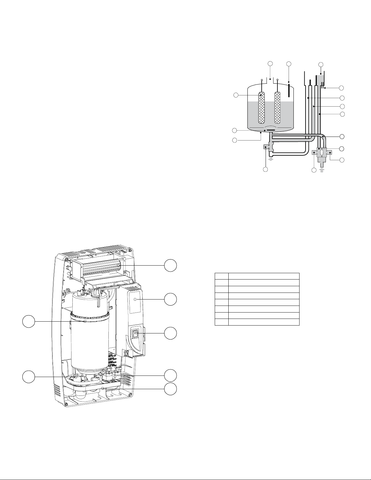
On a call for humidity, the Elite Steam controller will open the water fill valve (1) and allow water to
enter the cylinder. A flow restrictor (2) prevents the unit from filling too quickly or with too much
pressure. The water flows up the fill tube (3) and into the fill cup (7). Water then flows over the dam
in the fill cup (7), which creates a 1” air gap to prevent backflow of contaminated water into the feed
lines, and through the fill tube (4) and into the bottom of the steam cylinder (11). Any backflow or
overflow of water travels through the overflow hose (5) to the drain.
10
As the water fills the cylinder, it will reach the electrodes (10) and current will begin to flow. As the
water continues to fill the cylinder, the current will increase, and this is monitored by an amperage
transformer connected to one of the power wires (9) and located on the electronic controller. When
the desired current is reached, the fill valve will close (1) and the water will then begin to warm and
produce steam. If the water reaches the cylinder full probes (8) prior to reaching the desired current
level, the fill valve (1) will be closed to prevent overflow and the drain valve (13) will be opened to
12
11
drain away some water so as to move the water apart from the cylinder’s top. If the current rises too
much as the water fills the cylinder, the drain valve (13) will be activated to drain away some water
and reduce the current flow to acceptable levels. Note that, any time the drain valve is activated, the
tempering valve (14) will be opened for tempering the hot drained water down to 140 °F / 60 °C in
accordance to local and national standards.
Periodically, based on the incoming water conductivity, the unit will open the drain valve (13) and drain some water to reduce the mineral concentration.
A strainer (12) in the cylinder helps to prevent mineral debris from jamming the drain valve (13).
In case Elite Steam remains powered but idle, i.e. without producing steam, for more than 72 hours (3 days), the cylinder will be emptied to not have stagnant water
inside.
If there is no water in the cylinder, there will be no current flow and no steam production. The electrodes do not burn out, but they will eventually become completely
coated with mineral and the cylinder will then need to be replaced or cleaned.
9
13
8
7
6
5
4
3
15
2
14
1
Fig. 1.a
2
No. Description
1 Steam generator cylinder
2 Room blower/manifold (optional)
3
3 User interface/display
4 On/Off, SET buttons
5 Fill & tempering valves
6 Fill & drain connections
1
4
7
5
7 Drain valve
Tab. 1.a
6
Fig. 1.b
7
Page 5

2. Models
There are two basic models for steam distribution:
Duct Injection Direct Room Discharge
Fig. 2.a Fig. 2.b
Elite Steam comes in two capacities and voltages:
DS35 Duct Steam Injection, 35 gallons per day, (12 Lbs per h ou r ), 220 -240 V.
RS35 Room Steam Discharge, 35 gallons per day, (12 Lbs per hour), 220-240V.
DS20A Duct Steam Injection, 20 gallons per day, (7 Lbs per hour), 220-240V.
RS20A Room Steam Discharge, 20 gallons per day, (7 Lbs per hour), 220-240V.
DS15 Duct Steam Injection, 15 gallons per day, (5.5 Lbs per hour), 115-120V.
RS15 Room Steam Discharge, 15 gallons per day, (5.5 Lbs per hour), 115-120V.
8
Page 6
3. Installation
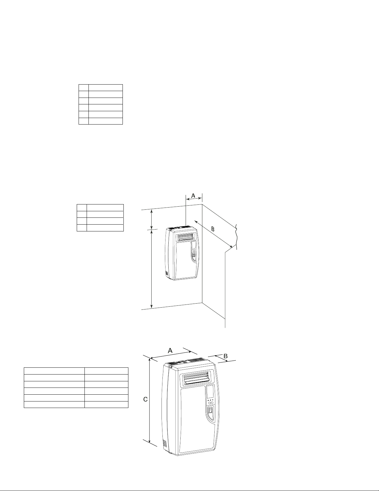
3.1 Positioning
The Elite Steam has been designed for wall mounting and, since it is an atmospheric steam humidifier, should be placed close to the point where the steam will be
used, to minimize the steam hose length (and the amount of condensate). Cer tain clearances must be maintained around the unit for safety and maintenance.
Duct Injection
A 6” (150 mm)
B 6” (150 mm)
C 6” (150 mm)
D 6” (150 mm)
E 24” (600 mm)
F max. 0.2°
Tab. 3.a
Direct Room Discharge
A 6” (150 mm)
B 36” (900 mm)
C 72” (1800 mm)
D 24” (600 mm)
Unit Dimensions: Duct and Room Units:
Fig. 3.a
D
Tab. 3.b
C
Fig. 3.b
A 13.5“ (341 mm)
B 8.1“ (204 mm)
C 23.7“ (600 mm)
Weight empty 18 lbs (8 kg)
Weight packaged 22 lbs (10 kg)
Weight installed with water 26 lbs (12 kg)
Tab. 3.c
Fig. 3.c
9
Page 7
3.2 Mounting
3.2.1 Removing the front cover
The front cover is secured by four screws located at the four corners
of the unit. Use a phillips head screwdriver to remove the four cover
screws. Then simply pull the front cover away from the back part of
the unit. Return it in reverse order.
Be careful not to over-tighten the screws.
Fig. 3.d Fig. 3.e
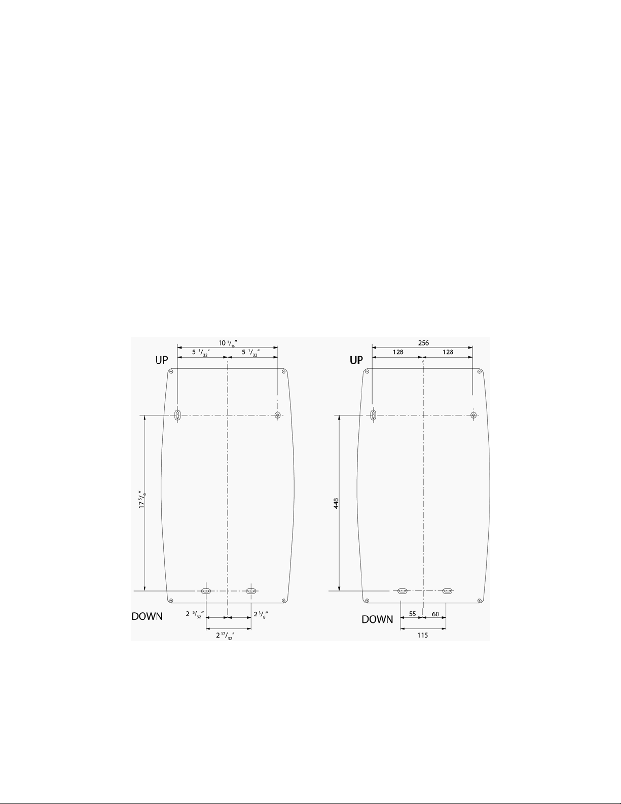
3.2.2 Fastening to the wall
Drill the wall according to the drilling template supplied; then secure Elite Steam firmly to the wall by the screws and anchors supplied.
Fig. 3.f
10
Page 8

3.3 Plumbing
3.3.1 Water supply
The Elite Steam must be supplied with COLD potable water (not softened or demineralized) having the following characteristics:
Instant flow rate: 0.12 gpm / 0.45 L/min
Connection: 1/4” O.D. Compression
Temperature limits: 34 to 104°F / 1 to 40 °C
Pressure limits: 15 to 116 psi / 1 to 8 bar
Hardness limits: <= 400 ppm CaCO3
Conductivity: 125 to 1250 µS/cm (micromhos)
Tab. 3.d
Fig. 3.g
The water feed line should be 1/2” copper, PVC or poly tubing run to within 3 feet of the humidifier, then bushed down to 1/4” O.D. poly to make the final connection
to the 1/4” O.D. compression fitting supplied with the unit. WARNING: WE RECOMMEND TO USE A SOFT POLY HOSE TO ABSORB THE WATER HAMMERING
IN ORDER TO AVOID DAMAGE TO THE FILL VALVE. The water line may be routed through the back or through the bottom of the unit. With poly tubing, an insert
should be used to support the tubing and prevent leaks. The fitting then threads onto the fill valve inlet located on the bottom of the humidifier. Note that there is a
strainer built into the fill valve fitting underneath the unit, which will require periodic cleaning, so be sure to allow clearance for access.
NOTE: softened water should NOT be used as it is generally corrosive to the electrode plating.
3.3.2 Water drain
The Elite Steam also requires connection to a drain. The drain line may be routed out the back of the unit or the bottom of the unit using the included angle fitting.
The drain water characteristics are:
Drain rate per hour: 0.7 gph / 2.6 L/h
Instant drain rate: 1.3 gpm / 5 L/min
Connection: 1-1/4” / 33 mm nominal diameter
Typical temperature: 140°F / 60 °C
Fig. 3.h
The drain line can be 1-1/4” schedule 40 PVC or CPVC, 1-1/4” copper, or 1-1/4” Polypropylene. In all cases, the drain tube is slipped over the drain outlet on the
bottom of the humidifier. It is not glued or otherwise attached to the humidifier, so it must be supported by itself.
If 1-1/4” schedule 40 PVC or CPVC is used, then a coupling should be used between the drain line and unit drain.
The Elite Steam includes a drain tempering valve that opens whenever the drain valve opens and flushes cool feed water into the drain line to insure that the drain
water temperature never exceeds 140 °F / 60 °C.
NOTE: Drain line must be trapped under the unit to prevent flash steam from condensing in the uni t cabinet.
11
Page 9

3.4 Steam distribution
3.4.1 Duct steam injection
The maximum allowed duct static pressure is 2 in WC.
The Elite Steam duct injection models include a plastic duct injection nozzle:
A 1.24” (31.5 mm)
B 1.96” (50 mm)
C 2.20” (56 mm)
D 2.26” (57.5 mm)
E 3.93” (100 mm)
F 0.31” dia. (8 mm)
G 0.86” dia. (22 mm)
H 1.18” dia. (30 mm)
I 0.47 or 0.87” (12 or 22 mm)
Or a stainless steel duct distributor:
Fig. 3.i
Fig. 3.l
To install the distributor pipes:
1. Cut a round hole in the side of the duct to match the steam pipe and condensate return.
2. Apply silicone sealant to the mounting plate and insert the pipe through the hole and secure it with 4 sheet metal screws.
3. Connect the steam and condensate hoses using the hose clamps supplied.
(Note: end support bracket supplied only with 36” and longer distributors.)
IMPORTANT: allow 2 feet of straight duct downstream of the distributor pipes for evaporation of the steam. Always allow 2 feet upstream. Turbulent air flow may require longer lengths.
3.4.2 Return Condensate Connection
The return condensate from the distribution manifold or the Thru-wall blower unit shall be returned through the knockout on top of the humidifier and be inserted into
the hole located on the top of the fill cup. See Fig. 3.k
.
Fig. 3.k
12
Page 10

3.4.3 Steam Hoses
NINETY PERCENT (90%) OF ALL OPERATION PROBLEMS ARE CREATED BY IMPROPER STEAM PIPING FROM THE HUMIDIFIER UNIT TO THE DUCT
DISTRIBUTOR PIPES. To avoid these problems, remember one simple fact when running the steam hose: steam naturally flows up hill, and condensate naturally
flows down hill. Run the steam hose or piping to av oid any kinks, sharp elbows, or low spots that could colle ct or restrict the flow of steam to the distributor pipe, or
the flow of condensate back to the humidifier. Support the hose adequately to avoid sags.
The following diagrams are to provide you with some guidelines. If you have a situation you are unsure of, please contact the factory for instructions.
IMPORTANT: Maximum length of rubber steam hose
2-45° elbows instead of 90°s.
Hose size = 7/8” (22 mm).
Hose size = 1-1/4” (30 mm).
Fig. 3.m
is 10 feet. Insulated copper tubing may be up to 20 feet. In all cases, minimize sharp bends and elbows – use
13
Page 11

3.5 Power wiring
Check that the power supply voltage to be connected matches the value indicated on the rating plate inside the
electrical panel.
Insert the power and ground connection cables into the electrical panel compartment using the strain reliefs
supplied, and connect to the terminals. An external fused disconnect must be installed.
All wiring must be in accordance with local, state and national electric codes.
NOTE: to avoid unwanted interference, the power cables should be kept separate from any control wiring.
All wiring must be in accordance with local, state and national electric codes.
Fig. 3.n
Model Code
DS15 110Vac 50/60Hz 5.5 2.5 1.86 16.88 AWG10 25
RS15 110Vac 50/60Hz 5.5 2.5 1.86 16.88 AWG10 25
DS20A 230Vac 50/60Hz 7 3.2 2.36 10.27 AWG12 20
RS20A 230Vac 50/60Hz 7 3.2 2.36 10.27 AWG12 20
DS35 230Vac 50/60Hz 12 5.4 4.05 17.61 AWG10 25
RS35 230Vac 50/60Hz 12 5.4 4.05 17.61 AWG10 25
NOTE: Tolerance allowed on main voltage = -15% to +10%
Fig. 3.o
Connect the wiring ground wire to the unit’s chassis ground, located just behind the power wiring terminal block.
Fig.3.p
Power supply
(single phase)
Steam Output
(lbs/hr)
Steam Output
(kg/h)
Connect power wires to the power terminal block located at the bottom left of the control module.
.
POWER
(kW)
CURRENT
(A)
EXTERNAL POWER WIRES EXTERNAL FUSE (A)
14
Page 12

3.6 Control wiring
Elite Steam allows connection of any simple or automatic humidistat, and safety devices such as high-limit
humidistat, air flow proving switch, and remote on/off.
3.6.1 Select Signal Type
REMARK: Select the proper type of control signal by the keyboard before
Proceed as follows:
1. Switch Elite Steam off.
2. Keep pressed both buttons, “reset/sel” and “drain”, and switch Elite Steam back on until the display shows
00 and the spanner
blinks; then release the 2 buttons.
Keep pressed “reset/sel” until the display shows 02. WARNING: do NOT confirm any value higher than 04. In
case, press “reset/sel” until the display goes back to the normal operating mode and restart from step 1.
3. Press “drain” (min. 1 second) to confirm: the display shows “P1” for 1 second and then P1’s current value;
set
will be displayed beside.
4. By pressing “reset/sel” the value of P1 will loop between 0 and 1: 0 = humidistat; 1 = external 0-10 Vdc
modulating signal
5. Press “drain” (min. 1 second) when done to confirm the new value of P1 and exit to the normal operating
mode.
6. Switch Elite Steam off: you can now proceed with connecting the control wiring.
Thread the control wiring through the bottom of the unit, and the strain relief (see photo at top of previous page), and then up the side of the control module to the top
right wiring terminal blocks.
Connect the control wiring to the control wiring terminal blocks found at the top right side of the control module.
3.6.2 Connect the E2 Humidistat for On/Off Operation:
1. Remove the humidistat from the base, squeeze the louvered base at the top and bottom.To remove the
humidistat from the wall, lift up on the humidistat and pivot top away from wall
2. Before wall mounting, please remove the gasket.
3. Before return air duct mounting, please remove the breakout piece.
4. If return air duct mounting, route wires between humidistat and base
5. Mount the sensor outside the house. Do not mount on South side of the house or in direct sunlight.
Place at least 4 feet away from any exhaust vent. If in air intake, place 1 foot or closer to outside wall.
Place at least 6” higher than possible snow. Do not route sensor wire near high voltage wires.
6. Connect the GND-IN terminals on the humidifier to the HUM terminals on the E2 Humidistat. Connect
the GND-24V terminals to the ACL-CAN terminals on the E2 humidistat.
Fig. 3.r
connecting the control wiring.
Fig. 3.q
15
Page 13

3.6.3 Modulating Operation:
Connect an external 0-10 Vdc modulating input between terminals IN-GND.
Connect any Safety Switches (high-limit, air flow switch, remote on/off) in series to terminals AB-AB. If no safety switches are used, then a jumper must be installed
between AB-AB. DO NOT apply any voltage to AB-AB.
3.6.4 Safety and High Limit Switches
Remove the jumper between terminals AB-AB and connect any simple high-limits, air flow switch, and remote contacts in series to terminals AB-AB; otherwise, if no
such dry contacts are available, the jumper must remain in place between terminals AB-AB. DO NOT apply any voltage to AB-AB.
3.7 Wiring Connections:
Terminals Input/Output Type Description
N1-GND-N2 NTC NTC air proving sensor
AB-AB 24 V Bridge Remote On/Off, Safety Switches
IN-GND 24 V Bridge Humidistat
NC-C-NO Dry contact Alarm relay
NO-C Dry contact External fan relay
24-GND 24 VAC Power for external humidistat
3.7.1 Wiring diagram of controller
Fig. 3.s
16
Page 14

4. Start-Up
IMPORTANT WARNINGS:
1. Before starting, check that the humidifier is in perfect condition, that there are no water leaks and that the electrical parts are dry;
2. Do not connect power if the humidifier is damaged or even partially wet!
When installation is completed, flush the supply pipe for around 10 minutes by piping water directly into the drain, without sending it into the humidifier;
this will eliminate any scale or residues that may cause foam when boiling.
4.1 Startup Checklist
Before starting the humidifier, the following should be checked:
Water is connected, the line has been flushed, and external valves are open.
Drain is connected, run to an open drain, and has a trap under the unit.
Electricity is connected in accordance with instructions, local codes and data labels in the unit.
The power fuses are installed and intact.
All control wiring is done and tested.
Airflow switch is wired to open on air flow loss.
Hi-limit humidistat is wired to open on humidity rise above set point.
Unit wires have been checked to make sure they and all connectors are tight from shipping.
The steam hose(s) are run correctly with no sags or kinks and sloped properly according to the manual.
Condensate hoses are run correctly with no sags or kinks and sloped properly according to the manual.
4.2 The Elite Steam Controller
The Elite Steam controller features a comprehensive information display that shows the operation of the system at a glance:
1. Display is % of nominal capacity
2. Maintenance required
3. Display is amperage (default)
4. Steam is being produced
5. Cylinder filling
6. Foaming
7. Cylinder full
8. Cylinder draining
9. LEDs indicate: power (yellow), operation (green) and alarms (red)
10. Drain button for manual draining of cylinder and confirming parameter values
11. ON/OFF button
12. Reset button to reset alarms and access parameters
13. Level of output: 33%, 66%, 100%
14. Fan relay is activated
14
13
1
2
3
4
5
6
7
8
9
1012
17
11
Fig. 4.a
Page 15

4.3 Starting Elite Steam
• Insure that the external power is turned on.
• Push the top part of the On/Off button so that the I part is in. The yellow Power LED will be lit. The Elite Steam is now ready to operate.
• When there is a call for humidity, Elite Steam will close its power relays and send power to the electrodes in the plastic steam generator. The green
Operation LED will light, indicating that operation has begun.
4.4 Starting with a new cylinder
When starting with a new cylinder, you should activate the cylinder cleaning function as follows:
1. Switch Elite Steam off.
2. Keep pressed both buttons, “reset/sel” and “drain”, and switch Elite Steam back on until the display shows 00 and the spanner blinks; then release the
two buttons.
3. Keep pressed “reset/sel” until the display shows 04.
WARNING: do NOT confirm any value higher than 04. In case, press “reset/sel” until the display goes back to the normal operating mode and restart from step
4. Press “drain” (min. 1 second): the cleaning starts.
During the cleaning, the electrodes are powered and water is filled in until it touches the high-level sensor OR the phase current equals 20 A, whichever occurs first.
After either of the events is detected, the boiler is fully discharged with the electrodes un-powered (the drain valve and the drain tempering valve are activated for 3
minutes). Warming the filling water helps washing out any mould release or dirt.
When starting the unit with a new or empty cylinder, it may take a significant amount of time (hours) for the unit to build up enough mineral concentration to reach
rated capacity. This time can be shortened by the addition of Alka-Seltzer or salt (teaspoon) through the steam outlet on top of the cylinder.
5. Operating Elite Steam
5.1 3.1 Displaying Information
By pressing the “reset/sel” button for 2 seconds, the display will loop from amperage to production in % of the maximum production to the hour counter and back to
amperage:
A
⇒ ⇒
%
⇒ ⇒
⇒ ⇒
A
1. Amperage: it is the value of the current that flows through the water making it boiling off (default display)
2. Production %: it is the current production expressed as a percentage of the nominal production
3. Hour counter: it is expressed in tens; for instan c e, when the display shows 13 the real hour value will be between 130 and 139 hours. Note that the hour
counter increment rate is proportional to the steam flow: e.g., in case the steam flow is 40% of the nominal value, the hour counter increment rate will be 40%
and after 100 hours of production the hour counter will show 4 which stands for 40 hours.
5.2 Changing The Maximum Production
The maximum production can be adjusted between 20% to 100% of the nominal production in steps of 5% in order to suit the environment characteristics:
1. Switch Elite Steam off.
2. Keep pressed both buttons “reset/sel” and “drain” and switch Elite Steam back on: the display shows 00 and the spanner
blinks; then release the two
buttons.
3. Keep pressed “reset/sel” until the display shows 01. WARNING: do NOT confirm any value higher than 04. In case, press “reset/sel” until the display goes
back to the normal operating mode and restart from step 1.
set
4. Press “drain” (min. 1 second) to confirm: the display shows “P0” for 1 second and then P0’s current value;
will be displayed beside.
5. By pressing “reset/sel” the value of P0 will loop from 20% to 100% in steps of 5%
6. Press “drain” (min. 1 second) when done to confirm the new value of P0 and exit to the normal operating mode.
5.3 Activating Manual Drain
Press and hold the “drain” button on the front of the unit until the cylinder is drained.
5.4 Resetting the hour counter
The hour counter should be reset every time the cylinder is changed in order to reset and restart the ineternal maintenance timer:
1. Switch Elite Steam off.
18
Page 16

2. Keep pressed both buttons “reset/sel” and “drain” and switch Elite Steam back on: the display shows 00 and the spanner
blinks; then release the two
buttons.
3. Keep pressed “reset/sel” until the display shows 03. WARNING: do NOT confirm any value higher than 04. In case, press “reset/sel” until the display goes
back to the normal operating mode and restart from step 1.
4. Press “drain” (min. 1 second) to confirm: the hour counter will be reset at once and Elite Steam will go back to the normal operating mode.
5.5 Using the E2 Humidistat
Press to select OFF, MANUAL or AUTO mode (if outdoor sensor is connected).
OFF mode: The humidifier is turned off.
MANUAL mode: The E2 will work to maintain the single humidity selected. You can set your desired humidity level by pressing
. The humidifier will turn ON or OFF according to your manual setting. (The humidifier will operate when the measure d relative
humidity falls more than 2% below the set point.) Humidity will have to be lowered when weather is colder or if condensation is
suspected.
Suggested Setting Outdoor Temperatures
15% -20˚F -29˚C
20% -10˚F -23˚C
25% 0˚F -18˚C
30% +10˚F -12˚C
35% +20˚F - 7˚C
40% +30˚F - 1˚C
AUTO mode: The E2 will automatically raise the humidity as the outdoor temperature increases. This provides the highest possible
humidity. The E2 will automatically lower the humidity as temperatures drop. This minimizes the risk of condens ation on cold surfaces
like windows. You can adjust the Auto Humidity Index Set Point from 0 (low) to 10 (high) by pressing
or . The Humidity Index is
based on the outdoor temperature and indoor humidity. The humidifier will switch ON/OFF according to th e calculated auto humidity
index set point. Lower Index settings are for older homes with less insulation and vapor barriers. Higher Index settings are for newer
homes with complete vapor barriers, triple pane windows and high R-value insulation. If condensation occurs reduce Index setting by 2
points until condensation stops.
NOTE If the outdoor temperature sensor fails, flashes and the unit will default to MANUAL mode.
• To toggle between indoor / outdoor temperature and indoor humidity: Press
.
• To change the temperature unit: Press °C / °F.
• To set the temperature / humidity offset in MANUAL or AUTO mode:
1. Simultaneously press
2. Use
3. Press
or to change the setting (-3 to 3).
and simultaneously or wait 5 seconds to confirm and move onto the next setting.
and when viewing the temperature or humid ity reading.
• Lo or Hi will flash on the display when:
MEASURE
LO HI
MENT
Indoor temp. Below
Outdoor
temp.
o
0
C
o
F)
(32
Below -
o
40
C (-
o
F)
40
Humidity Below
10%
Above
o
99
F(37oC)
Above
o
50
C
o
(122
Above
90%
F)
• If power is lost, current settings are retained.
WARNING:
Do not allow excess humidification. Excess humidity can cause condensation and enabl e mold and mildew growth.
or
19
Page 17

5.6 Alarms
In the event of an alarm, the red alarm LED will flash, the alarm relay will close, and the alarm code will flash in the display. Multiple alarms will flash in sequence,
alternating with the main display. Pressing the sel button for 2 seconds will reset the alarms, although still active alarms will cont inue to display.
Display Description Action Notes
E0 Control board configuration not valid Unit disabled Turn off, check control board, reprogram
E1 High current alarm Unit disabled Turn off, check connections, check cylinder (no
E2 Low production, low supply water
conductivity or excessive foam/limescale in
the cylinder
E3 Cylinder lifetime expired (1200 hours) Press “reset/sel” key for 1 seconds to reset. The warning will be
E4 Fill alarm, unable or slow fill
(current does not increase within timeout)
E5 Drain alarm, unable to drain
(current does not decrease within timeout)
E6 Cylinder exhausted
(critical performance detected)
E7 Foam detected Press “reset/sel” key for 1 seconds to reset If it continues, do some cleaning cycles (read chap.
E8 Cylinder lifetime expired (2000 hours) Reset the hour counter (read chap. Resetting the hour counter”) Change the cylinder.
E9 High controller temperature (above 176 °F /
80 °C)
Unit disabled.
Press “reset/sel” key for 1 seconds to reset.
displayed 50 hrs later until the hour counter is reset and the
cylinder replaced.
Press “reset/sel” key for 1 seconds to reset, otherwise the warning
will be reset automatically every 10 minutes until the supply water
is available again.
Press “reset/sel” key for 1 seconds to reset Check drain valve and drain connection
The warning is automatically reset if Elite Steam can produce the
demand, otherwise turn off and then on.
The warning is automatically reset if the temperature decreases
below 176 °F / 80 °C.
limescale bridges between electrodes, no electrodes
short-circuited)
Check supply water conductivity (too low?), replace
the cylinder.
Change cylinder (not urgent)
Check water supply and fill valve; check drain valve
for leakage
Change cylinder (urgent)
“Starting with a new cylinder”)
Check the ambient temperature, replace the
controller.
20
Page 18

6. Trouble-Shooting
problem causes solutions
The humidifier does not turn on 1. no electrical power
2. on/off switch of the humidifier in position 0 (open)
3. control connectors improperly connected
4. blown fuses
5. transformer failure
1. check the safety devices upstream from the humidifier and the
presence of power
2. close the switch on the panel: position I
3. check that the connectors are properly inserted in the terminal block
4. check the condition of fuses
5. check that the proper voltage is connected and turned on
The humidifier does not start operation 1. remote ON/OFF contact open
The humidifier fills with water without producing
steam
The humidifier wets the duct 1. the distributor is not installed correctly (too near the
The humidifier wets the floor below 1. the humidifier drain is blocked
2. the humidistat has not been connected correctly
3. humidistat failure
4. control signal not compatible with the type set
5. value measured by the sensor/s higher than the
corresponding set point
1. high steam back pressure
2. fill valve strainer clogged
3. mineral in the fill cup
4. drain solenoid valve leaking
top of the duct or the condensate return is blocked)
2.system over-sized
3.humidifier active when the fan in the duct is off
2. the supply water or overflow circuit has leaks
3. the condensate drain pipe does not bring the water
back to the drain pan
4. the steam hose is not properly fastened to the cylinder
Water in the cylinder turns black 1. minerals in the cylinder have overconcentrated and
Heavy arcing occurs within hours of startup 1. The feed water contains large amounts of Iron,
Humidifier continuously fills and drains without
producing steam
problem causes solutions
are deteriorating the electrodes.
Copper or other conductive contaminants.
1. Mineral has bridged between the electrodes.
2. There is back pressure from the steam hoses or duct.
3. The flow regulator in the fill valve is broken or out
of place.
4. Water conductivity is very high.
5. Water is foaming excessively.
1. close ON/OFF contacts
2. check the external connection
3. replace the humidistat
1. check that the steam hose is not kinked or sagging, trapping
condensate
2. clean the fill valve strainer
3. clean the fill cup
4. check for voltage at the drain solenoid valve and/or drain solenoid
replacement
1. check that the steam distributor is installed correctly
2. decrease the steam production set on the control
3. check the connection of the device (flow switch or differential
pressure switch) slaving the humidifier to the ventilation in the duct
1. clean the drain assembly and pan
2. check the entire water circuit
3. check the correct position of the condensate drain hose in the drain
pan
4. check the fastening of the hose clamps on the steam outlet
1. Check for sags & kinks that could trap condensate in the steam
hoses that could cause a back pressure on the cylinder.
2. Check the duct static pressure.
3. Check the fill valve and inlet strainer.
4. Check the drain valve operation.
5. Correct installation problems and replace cylinder.
1. Contact the factory for an optional drain timer to force additional
drains to control the minerals.
2. If you are using a softener, check the salt being used. If it contains
any additives, discontinue use, flush all lines and convert to pure salt
or unsoftened water.
3. Check the electrodes in the cylinder to be sure they were not
damaged in shipping.
1. Clean or replace the cylinder.
2. Check the steam hoses for kinks or gullies that might be trapping
condensate.
3. Replace the fill valve.
4. Consider using a mix of demineralized water with raw water.
5. Check cylinder - replace if exhausted. If feed water contains silica
or nitrates, install a 1 micron water filter.
21
Page 19

7. Maintenance
7.1 Periodic checks
• After one hour of operation: Check that there are no significant water leaks.
• Every fifteen days or no more than 300 operating hours: Check operation, that there are no significant water leaks and the general condition of the
cylinder. Check that during operation there is no arcing between the electrodes.
• Every three months or no more than 1000 operating hours: Check operation, that there are no significant water leaks and, if necessary, replace the
cylinder. Check that there are no blackened parts of the cylinder. If there are blackened parts of th e cylin der, che ck the co n d i tion o f the electrod es,
and if necessary replace the cylinder.
• Annually or no more than 2500 operating hours: Replace the cylinder.
CAUTION: ALWAYS DISCONNECT THE MAIN POWER BEFORE DOING MAINTENANCE!
CAUTION: always disconnect the main power before touching the cylinder in the event of leaks, as current may flow through the water.
7.2 Cylinder maintenance
The life of the cylinder depends on a number of factors, including: the amount and type of mineral in the water, the correct use and sizing of the humidifier, and the
output, as well as careful and regular maintenance.
IMPORTANT WARNINGS
The humidifier and its cylinder contain live electrical components and hot surfaces, and therefore all service and/or maintenance operations must be performed by
expert and qualified personnel, who are aware of the necessary precautions. Before performing any operations on the cylinder, check that the humidifier is
disconnected from the power supply. Remove the cylinder from the humidifier only after having drained it completely using the manual “drain” button or procedure.
Check that the model and the power supply voltage of the new cylinder correspond to the data on the rating label.
7.2.1 Replacing the cylinder
IMPORTANT WARNING: the cylinder may be hot. Allow it to cool before touching it or use protective
gloves.
To replace the cylinder:
• completely drain the cylinder by pressing and holding the “drain” button until the cylinder is empty;
• turn the humi di fier off and disconnect the main power;
• remove the cover;
• duct version:
o remove the steam hose from the cylinder;
o flip up the cylinder holding bracket and lift the cylinder out of the unit;
• room version:
o undo the 2 bolts of the embedded fan;
o flip up the cylinder holding bracket;
o disconnect the distributor from the cylinder and lift the cylinder out of the unit;
• disconnect the electrical connections from the top of the cylinder;
• install the new cylinder in the humidifier by performing the previous operations in reverse.
WARNING: Electrical connections to the cylinder must be tight or possible fire hazard may result.
Threaded nuts on power wires must be connected with 22 to 29 inch-pounds of torque (2.5 to 3.3 Nm).
Fig. 7.a
7.2.2 Maintenance of the other plumbing components
IMPORTANT WARNINGS:
• External power must always be disconnected when performing any maintenance on the humidifier.
• When cleaning the plastic components do not use detergents or solvents;
• Scale can be removed using a solution of Lime-A-Way
Cleaning the fill valve:
After having disconnected the cables and the hoses, remove the valve and check the condition of the inlet filter; clean if necessary using the same cleaning solution
as for the steam cylinder and a soft brush.
Cleaning the drain valve:
Remove the valve body, clean if necessary using the same cleaning solution as for the steam cylinder and a soft brush.
Cleaning the drain pan:
Clean the pan of any mineral deposits and check that the water flows freely from the pan to the drain at the drain valve.
Cleaning the supply, fill, overflow pipes:
Check that these are clear and clean or replace if necessary.
IMPORTANT WARNING: after having replaced or checked the plumbing, check that components have been reconnected correctly with the proper seals. Re-start
the humidifier and perform a number of cleaning cycles (from 2 to 4, read chap. “Starting with a new cylinder”), then check for any water leaks.
®
, CLR®, or 5% phosphoric acid, then rinse with water.
22
Page 20

7.3 Replacement Parts
Item Part No. Description
1 See the table below Steam generator cylinder
2
7549 35-17 Internal cables kit
3 7551 35-18 On/off switch
4
5 7544 35-19 Blower filter
6 7536 35-20 Internal steam distributor for room blower
7
8
9 7442 35-21Ninety-degree drain adapter
7548 35-22 Fill cup
7553 35-25 Cover holding screws
Cylinders
(item 1)
7523 5.5 lbs/h 2.5 kg/h 110 Low and Normal 125-1250 15-14 Steam Cylinder
7508A 7 lbs/h 3.2 kg/h 230 Normal 350-1250 20-14A Steam Cylinder
7524 12 lbs/h 5.4 kg/h 230 Normal 350-1250 35-14 Steam Cylinder
7543 12 lbs/h 5.4 kg/h 230 Low 125-350 35-15 Steam Cylinder Low Conductivity
7552
Rated steam flow Vac 1-phase Supply water conductivity (µS/cm) Description
35-16 Internal filter and gasket valid for all cylinders
7532 15-1 Control module 110 VAC 1-phase
7533 35-1 Control module 230 VAC 1-phase
7534 15-2 Room blower assembly 110 VAC 1-phase
7535 35-2 Room blower assembly 230 VAC 1-phase
7537 15-3 Fill/tempering valve 110 VAC 1-phase
7538 35-3 Fill/tempering valve 230 VAC 1-phase
7539 15-4 Drain valve 110 VAC 1-phase
7541 35-4 Drain valve 230 VAC 1-phase
7546 35-23 Internal hoses kit for room versions
7547 35-24 Internal hoses kit for duct versions
Fig. 7.b
23
Page 21

8. Technical Specifications
Steam flows, VAC, kW 5.5 lbs/hr (2.5 kg/h): 110 VAC 1-phase 50-60 Hz, 1.86 kW
Steam pressure 39.37 in WC / 980 Pa For duct only
Dimensions (mm ) 24” x 14” x 8”
Weight empty/packaged/installed with water 18/22/26 lbs.
IP class IP20
Electrode power cables 14 AWG
Power relays 2 x 30 Amp on board
Ground connection Faston
Input water type Potable water no demin. or softened water
Conductivity range 125-1250 µS/cm Special cylinders for cond. < 350
Water fill connection 1/4” O.D. Compression Adapter to ¾” FPS
Water fill - instant flow 0.09 – 0.12 gpm
Drain connection 33 mm O.D. Adjustable from horizontal to vertical.
Drain water temp < 140°F
Drain flow Max 1.3 gpm
Embedded fan flow 71 cfm
7 lbs/hr (3.2 kg/h): 230 VAC 1-phase 50-60 Hz, 2.36 kW
12 lbs/hr (5.4 kg/h): 230 VAC 1-phase 50-60 Hz, 4.05 kW
(Height x Width x Depth)
(600 x 341 x 204 mm)
(8/10/12 kg)
(0.35 – 0.45 l/min)
May be from back or bottom of unit.
drain tempering device
(< 60°C)
(max 5 l/min)
Direct Room Discharge Only
(120 m³/hr)
Limited Warranty
DS, RS and CS Humidifiers, if properly registered by the return of the attached warranty registration to General Filters, Inc., are warranted to the consumer
against defects in materials and workmanship for a period of two years from the date of installation, so long as the product has been installed and operated in
accordance with all appropriate manuals and wiring diagrams. Replacement or routinely replaceable parts such as steam cylinders and gaskets, are not
covered by this limited warr anty or any other warranties. Any other defective parts will be repaired without charge except for removal, reinstallation and
transportation costs. To obtain repair service under this limited warranty, the consumer must send the defective part to General Filters, Inc.
THERE ARE NOT EXPRESS WARRANTIES COVERING THIS HUMIDIFIER OTHER THAN AS SET FORTH ABOVE. THE IMPLIED WARRANTIES OF
MERCHANTABILITY AND FITNESS FOR A PARTICULAR PURPOSE ARE LIMITED IN DURATION TO TWO YEARS. THE MANUFACT URER ASSUMES
NO LIABILITY IN CONNECTION WITH THE INSTALLATION OR USE OF THIS PRODUCT, EXCEPT AS STATED IN THE LIMITED WARRANTY. THE
MANUFACTURER WILL IN NO EVENT BE LIABLE FOR INCIDENTAL OR CONSEQUENTIAL DAMAGES.
This limited warranty gives you specific legal rights, and you may also have other rights which vary from state to state. Some states do not allow either
limitations on implied warranties, or exclusions from incidental or consequential damages, so the above exclusion and limitation may not apply to you.
Any questions pertaining to this limited warranty should be addressed to General Filters, Inc. General Filters, Inc. has elected not to make available the
informal dispute settlement mechanism which is specified in the Magnuson-Moss Warranty Act.
General Filters, Inc. Canadian General Filters, Inc.
43800 Grand River 39 Crockford Blvd.
Novi, MI 48375-1115 Scarborough, ON M1R 3B7
www.generalfilters.com
www.cgfproducts.com
Notes
24
 Loading...