

Page 1

OPERATOR’S MANUAL
Safety, Operation & Service Information
RIP-R-STRIPPER Floor Covering Stripper
Model: FCS16
Form: GOM4240301EU, Version 1.0, Original Instructions
• Do not discard this manual.
• Keep manual readily available for reference during operation or when servicing product.
• Before operation, read and comprehend operator manual content.
• Customer Service: 001 507 451 5510
• Customer Service Telefax: 001 507 451 5511
Note: There is no charge for Customer Service.
Internet Address: http://www.generalequip.com
•
Email: general@generalequip.com
•
Mailing Address:
•
General Equipment Company, 620 Alexander Dr. S.W., P.O. Box 334, Owatonna, MN 55060, USA
EUROPEAN REPERESENTATIVE
• Customer Service: ( + 31) 5 23 63 82 86
• Internet Address: http://www.eurogate-international.com
Email: info@eurogate-international.com
•
• Mailing Address: Eurogate International, Galilieistraat 6, 7701 SK Dedemsvaart, The Netherlands
Product covered by this manual complies with mandatory requirements o f 2006/42/EC.
Copyright 2016, General Equipment Company, All rights reserved.
Page 2
FCS16 RIP-R-STRIPPER FLOOR COVERING STRIPPER
Symbol
Meaning
Symbol
Meaning
Warning,
Material
Warning,
Material
OPERATIONAL DISCLAIMER
specific floor covering from any specific work surface.
damage, personal injury and/or death.
FORM GOM4240301EU, VERSION 1.0
TABLE OF CONTENTS
1 INTRODUCTION ……………………….…………… 1
2 SAFETY SYMBOLS………………………..……….. 1
3 SAFETY INSTRUCTIONS ………….……………… 1
4 MACHINE SPECIFICATIONS ………….………….. 3
5 STANDARD PRODUCT & ACCESSORIES ……... 3
6 MACHINE SET-UP .……………………….………… 4
7 APPLICATION THEORY & TECHNIQUES ……… 5
8 OPERATING INSTRUCTIONS ………….…………. 7
9 MAINTENANCE INSTRUCTIONS ………………… 8
10 TROUBLESHOOTING ……………………………… 8
11 STORAGE ……………………………………………. 9
12 END OF LIFECYCLE ……………………………….. 9
13 DECLARATION OF CONFORMITY ………………. 9
Wear Ear
Protection
Wear Eye
Protection
Wear
Protective
Gloves
Wear Safety
Shoes
Wear Breathing
Protection
Disconnect
From Power
No Open
Flame
No Smoking
No Active
Mobile Phone
No Food Or
Drink
Flammable
Explosive
Warning, Toxic
Material
Warning,
Electricity
Warning, Body
Entrapment
Warning, Sharp
Element
Warning, Floor
Level Obstacle
Warning, Drop
Off
Warning, Slippery
Surface
1 INTRODUCTION
Congratulations on your decision to purchase a General Equipment light
construction product. From our humble beginnings in 1955, it has been a
continuing objective of General Equipment Company to manufacture
equipment that delivers uncompromising value, service life and investment
return. Because of this continuous commitment for excellence, many products
bearing the General name actually set the standard by which competitive
products are judged.
When you purchased this product, you also gained access to a team of
dedicated, knowledgeable, support personnel that stand willing and ready to
provide field support assistance. Our team of sales representatives and inhouse factory personnel are available to ensure each General product delivers
the intended performance and product s afety you expect. Our personnel can
readily answer your questions or concerns regarding proper applications,
service requirements and w ar ra nt y rela ted pr oblem s .
The RIP-R-STRIPPER is intended for use in removing VCT and linoleum tiles,
soft sheet materials (PVC, rubber, linoleum, etc.), glued carpet, adhesives,
mastics and material residues from dry wood and cement surfaces in a
nonexplosive atmosphere. It is not intended to remove ceramic tile. The
machine is operated by one adult of proper operator e xperience/skill/ common
sense, height, weight, strength and physical condition.
If you have any questions or concerns about this product, please feel free to
contact our European Representative or Customer Service Department during
normal business hours using the contact information located on the front cover
of this manual.
Sincerely,
The General Equipment Team
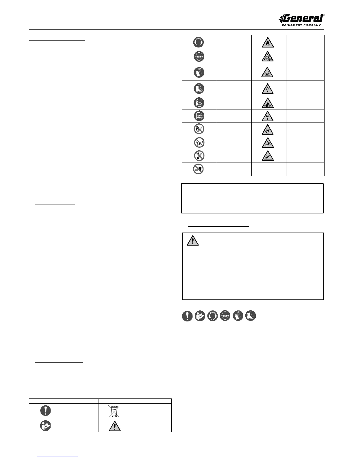
2 SAFETY SYMBOLS
The following safety alert symbols identify important safety messages in this
manual. When you see these symbols, be alert to the possibility of personal
injury and carefully read the message that follows. Always utilize correct blades
or extension cords for use with the RIP-R-STRIPPER.
SAFETY SYMBOLS & MEANINGS
Action
Required
Read Manual
English-EN 1
No Trash
Containers
General Warning
The manufacturer of this RIP-R-STRIPPER makes no warranty or
guarantee it is merchantable and/or suitable for a specific job application
and that it will have the capability and power required to remove any
3 SAFETY INSTRUCTIONS
• These safety instructions provide guidelines to promote safety
and efficiency with the RIP-R-STRIPPER.
• No warranty, guarantee or representation is made by
manufacturer as to abs olute c or r ect ne ss or suf fic ie nc y of an y
information or statement.
• Safety instructions are intended to deal with common practice s
and condition s en countered in use o f RIP-R-STRIPPER and are
not intended to be all inclusive.
• Not following instructions in this manual can result in property
BEFORE OPERATING
1. BEFORE operating RIP-R-STRIPPER, read this manual and view
applicable Safety/Operational Video to familiarize each operator with
correct operating procedures.
2. Visually inspect RIP-R-STRIPPER per MAINTENACE INSTRUCTIONS
STEPS 5 through 9 of this manual.
3. Determine RIP-R-STRIPPER is in original, factory configuration and has
4. Always start and stop RIP-R-STRIPPER according to instructions to
Physical Exertion/Body Strain
Operating RIP-R-STRIPPER requires proper physical stamina, mental
alertness and is strenuous. Take work breaks to maintain stamina an d
alertness. If you have condition(s) that might be aggravated by strenuous work,
check with doctor BEFORE operating.
not been modified in any manner. If questions arise about possible
modifications, contact the European Representative or Customer Service
Department BEFORE utilization. There is no charge for this service.
minimize possibilit y of un e xpect ed or u nc o ntr oll ed blade/accessory
movement. Know how to stop unit in an emergency.
Page 3
FCS16 RIP-R-STRIPPER FLOOR COVERING STRIPPER
FORM GOM4240301EU, VERSION 1.0
Vibration
Prolonged use of RIP-R-STRIPPER (or other, similar machines) exposes
operator to vibrations which may produce Whitefinger Disease (Raynaud's
Phenomenon). Continuous and regular users should closely monitor condition
of hands and fingers. After each pe riod of use, exercise to restore normal blood
circulation. If any symptoms appear, seek medical advice immediately.
Noise
RIP-R-STRIPPER and actual floor covering removal process creates exposure
to high noise emission levels that can result in hearing loss or damage. Hearing
protection is required while operating or when near operating equipment.
Continuous and regular operators should have their hearing checked regularly.
Clothing
Clothing must be sturdy, snug fitting, but allow complete freedom of movement.
Never we ar loose fitting jackets, scarves, neckties, jewelry, flared or cuffed
pants or anything that could become caught on controls or moving parts.
Properly secure eyeglasses, hearing aid devices and other medical related
devices. Wear long pants to protect legs. Protect hands and improve grip with
heavy duty, nonslip gloves. Wear and properly lace sturdy boots with nonslip
soles. Steel-toe d safet y sh oes ar e mandatory. Wear approved safety hard hat
where there is dang er of head injuries and/or appr ove d bre at hing mask where
danger of airborne foreign particulate contamination is present.
Flying Debris
Floor covering removal process can result in flying debris. Eye protection and
appropriate safety apparel is required when near or operating RIP-RSTRIPPER. DO NOT operate unit with onlo okers or animals close by.
Back Care & Proper Lifting Procedures
Operators will be required to lift RIP-R-STRIPPER as demanded by specific job
applications. When lifting, three or more people are required. Maximum lifting
weight per person is 23 Kg (50.7 lbs) per NIOSH standards. Utilize proper lifting
techniques to minimize fatigue and back-related injuries.
TRANSPORTATION
1. When transporting RIP-R-STRIPPER, remove extension cord and store.
Remove accessory blade from machine and store per INSTALLING &
REMOVING ACCESSORY BLADES in MACHINE SET-UP section of this
manual when in following operating conditions:
a) To and from jobsite.
b) Longer distances while being repositioned on jobsite.
c) Traversing up and down stairways.
d) Performing maintenance and/or repairs.
e) Lifting/lowering from transportation vehicle.
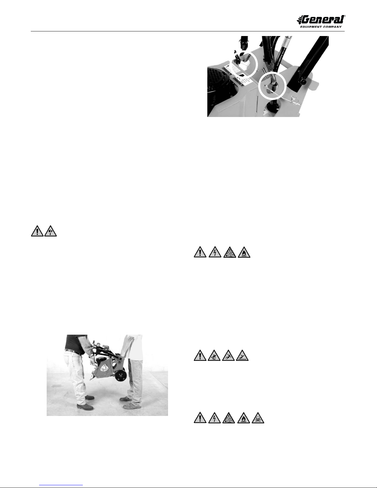
2. To use personnel to lift/lower machine, use handles as shown and/or side
handles near rear of unit. FIGURE 1
FIGURE 2
NOTE: This location may not always be the exact center of gravity for the
machine. DO NOT use lift device until device limitations and operation are
understood by all applicable personnel.
4. To reduce storage area and minimize damage, transport RIP-RSTRIPPER in normal upright position with operator handle folded relative
to main frame. Refer to MACHINE SET-UP section of this manual.
a) DO NOT allow operator handle and main frame direct contact
with each other while transporting. Provide proper protection
between RIP-R-STRIPPER components and vehicle.
b) DO NOT drop unit directly against exciter plate. Provide
support block under main frame to prevent direct contact
and/or damage to exciter plate and related components.
5. All equipment must be secured in/on vehicles with suitable strapping or
tie downs.
DETERMINATION OF POTENTIAL SUBSURFACE HAZARDS IN
PROPOSED FLOORING REMOVAL LOCATION(S)
RIP-R-STRIPPER operator handle grips are constructed of non-metallic
composite material and do not guarantee operators will be properly insulated
from contact with charged electrical cables. RIP-R-STRIPPER and related
accessories are not classified as insulated.
BEFORE attempting to remove any floor covering materials, identify/mark all
potential subsurface hazards in proposed flooring removal location(s). Many
utilities/other agencies will perform these tasks at minimal or no cost.
Subsurface hazards may include, but may not be limited to the following:
1. Buried debris, rotted timbers or wood planking.
2. Buried pressurized pipelines (e.g. natural gas, propane, etc.)
3. Buried electrical cables.
DETERMINATION OF POTENTIAL ABOVE SURFACE HAZARDS IN
PROPOSED FLOORING REMOVAL LOCATION(S)
FIGURE 1
3. To use mechanical device to lift/lower machine, attach chain and suitable
attachme nt device to lifting bail area behind electric motor. FIGURE 2
English-EN 2
Normal RIP-R-STRIPPER use is on level surfaces. Avoid other surface
conditions which can be dangerous. Special care must be exercised on
slippery, and/or difficult/uneven surfac e s. Watch for cracks, high spots/other
surface irregularities or drop offs to lower floor levels. Remove any trip/fall
hazard BEFORE operating RIP-R-STRIPPER. Keep proper footing and
balance at all times.
OPERATIONAL HAZARDS
1. RIP-R-STRIPPER is designed to substantially enhance machine control
and reduce operator fatigue provided accessory tool does not directly
contact larger, protruding obstructions (anchor bolts, pipes, nail heads,
columns, openings, large cracks, utility outlets, material variances, etc., or
any objects protruding from work surface). Such contact can result in
rapid and jerky movement of machine and/or loss of machine control.
Page 4

FCS16 RIP-R-STRIPPER FLOOR COVERING STRIPPER
FRAME STRUCTURE
Unitized, welded steel plate.
DRIVE SYSTEM
Random orbit, direct shaft mount.
NUMBER
RUBBER MOUNTS
4
NUMBER BLADE
OSCILLATIONS
1440 per minute
WIDTH
368 mm (14-1/2 inches)
OPERATOR HANDLE
WIDTH
584 mm (23 inches)
TRANSPORT LENGTH
711 mm (28 inches)
OPERATING LENGTH
864 mm (34 inches)
TRANSPORT HEIGHT
584 mm (23 inches)
OPERATING HEIGHT
1067 mm (42 inches) maximum handle
extension.
WEIGHT
59.9 Kg (132 lbs), with external weig ht , less
blade.
EXTERNAL WEIGHT
6.3 Kg (14 lbs) each
ELECTRIC MOTOR
246W (0.33 HP), 1440 RPM, 5.5 full loaded
capacity circuit to properly function.
EXTENSION CORDS
Minimum rating for non-manufacturer supplied
a maximum cord length of 25 m.
OPERATING
ENVIRONMENTS
Non-hazardous type locations.
REQUIRED NUMBER
OF OPERATORS
1
Description
North America
Europe
Model
FCS16
Noise Level
73 db
Vibration Level
13 m/s²
FORM GOM4240301EU, VERSION 1.0
2. The floor covering material removal process can produce sparks, dusts
and other foreign particle contamination that can result in fire and/or
explosion depending on existing jobsite conditions.
3. Many covering materials, adhesives or mastics can contain asbestos and
other chemicals that are known to cause physical harm and/or affect the
environment.
4. Excessive water, and/or other conductive materials on work surface can
result in electrocution of operator and/or other personnel.
Preventive Measures :
• Operator must maintain physical and mental alertness. Be prepared for
unexpected blade contact with protrudi ng anchor bolts, etc. and be
capable to sense level of machine control they have.
• DO NOT operate RIP-R-STRIPPER on jobsite where kickback forces can
allow body parts to come in direct contact with vertical wall, foundation or
other support type structures. Maintain a safe and reasonable distance
from these structures.
• Maintaining proper operating stances is one of the most IMPORTANT
and EFFECTIVE procedures to control kickback. Refer to OPERATOR
STANCES in OPERATING INSTRUCTIONS section of this manual for
more information.
• Remove water and/or conductive materials by industry-approved and/or
accepted practice BEFORE removing floor covering. Determine RIP-RSTRIPPER is properly grounded and extension cords are free of cuts.
Abrasions and/or exposed cable strands.
• Dust and other particle contamination can be controlled by use of
appropriate industrial-type vacuum system to remove/control dust and
other particle contami n atio n from wo rk surfac e .
4 MACHINE SPECIFICATIONS
NOISE & VIBRATION EMISSIONS
RIP-R-STRIPPER POWER SOURCE
The RIP-R-STRIPPER is designed to operate from a clean, 10 ampere, 220
VAC, 50 Hz, nominal power source. Clean power refers to amperage available
from individual electrical circuit selected.
Additional electrical products already using same circuit will reduce available
amperage resulting in starting/operational difficul ties. Check proper voltage and
amperage levels i n addi ti on to po w er s ource being properly groun de d.
Proper voltage and amperage to electric motor is essential for maximum
productivity and service life. Low voltage and amperage will cause motor to
overheat and can cause unrepairable damage to motor and related controls. An
improperly grounded circuit increases risk of electric shock. A qualified
electrician may need to be consulted.
NOTE: Motor is equipped with automatic thermal protection, stopping
motor before major internal damage occurs. If this situation occurs and
motor has properly cooled, motor reset switch must be manually activated
to restart. FIGURE 4
amperes @ 220 VAC, 50 HZ, thermally
protected. Motor requires clean (no other
electric products on same circuit) 10 ampere
extension cords, HO5VVF (3 x 1.5 mm²) up to
FIGURE 3
ELASTOMERIC
English-EN 3
FIGURE 4
5 STANDARD PRODUCT & ACCESSORIES
Refer to FIGURE 3 for overview description of standard components included
in machine. Included in shipment for FSC16 RIP-R-STRIPPER should be the
following:
1 each, Model FCS16 RIP-R-STRIPPER
1 each, Adjustable s ection of operator handle
1 each, 102 mm wide straight blade, part # FCS16-1100
1 each, 254 mm wide straight blade, part # FCS16-1300
1 each, Final inspection form
1 each, Safety and operational DVD
Page 5

FCS16 RIP-R-STRIPPER FLOOR COVERING STRIPPER
Part #
Description
Weight
(in Kg)
FCS16-1100
Blade, straight, 102
0,2
FCS16-1200
Blade, angled, 152
ONLY.
0,9
FCS16-1300
Blade, straight, 76 mm
0,2
FCS16-1500
Blade, scoring, 203
surfaces ONLY.
0,2
FCS16-1600
Blade, scoring, 203
surfaces ONLY.
0,2
FCS16-1900
Blade, straight, 406
beveled edge.
0,9
FCS16-0230
Block, weight
6,3
FCS16-0260
T-Handle Hex Key,
0,1
FORM GOM4240301EU, VERSION 1.0
ACCESSORIES
NOTE: All blades are for use in general purpose projects on both wood and
cement surfaces unless otherwise designated.
mm x 152 mm, dual
bevel edged.
mm wide, single
beveled edge. For use
on cement surfaces
x 254 mm wide, single
beveled edge.
mm wide, beveled
edge FACING UP.
For removing glued
carpet, and sheet type
linoleum, rubber, PVC,
etc., from cement
mm wide, beveled
edge FACING DOWN.
For removing glued
carpet, and sheet type
linoleum, rubber, PVC,
etc., from WOOD
mm wide, with support
bracket, single
4.7 mm (3/16 inch)
6 MACHINE SET-UP
Open shipping carton immediately upon receipt. Remove RIP-R-STRIPPER
from carton. Visually inspect contents for freight damage and/or missing parts.
If shipping damage is evident, contact delivering carrier immediately to arrange
for an inspection of dam a ge by their claims representative. DO NOT DESTROY
OR DISCARD SHIPPING CARTON UNTIL INSTRUCTED BY AUTHORIZED
REPRESENTATIVE OF CARRIER OR FACTORY. If missing parts are
detected, notify your deal e r who will as si st you in obtaining them.
NOTE: If ordered with RIP-R-STRIPPER, optional blades and accessories can
be shipped separately or included in shipping carton.
NOTE: RIP-R-STRIPPER is shipped from factory with operator handle
assembly uninstalled to main frame. All lubrication fittings are lubricated at
factory and will not require further servicing until first scheduled maintenance.
INSTALLING ADJUSTABLE OPERATOR HANDLE
Installation of adjustable portion of operator handle will require a level work
surface of appropriate size and height.
1. Unfold lower portion of operator handle from storage position and insert
ball-detent pins through operator handle and main frame. Check balldetent pins are inserted to fully expose ball detent and properly lock in
position to prevent unexpected handle movement. FIGURE 5
English-EN 4
FIGURE 5
2. Remove threaded handle knobs from low er, fi xe d porti on of op er at o r
handle in STEP 1.
3. Install adjustable portion of operator handles into fixed portion with
adjustment slots pointing back toward operator to prevent inadvertent
separation from fixed handle portion. Check handles slide freely once
installed. FIGURE 6
4. Reinstall threaded knobs, adjust handles to desired height then finger
tighten knobs to secure handles firmly in place. FIGURE 6
FIGURE 6
5. To readjust handle height, loosen threaded knobs approximately 13 mm
(1/2 inch), adjust handle to desired height then finger tighten knobs to
secure handles firmly in place.
6. Inspect all fasteners for looseness. Tighten as necessary.
7. Determ i ne all components of RIP-R-STRIPPER allow for proper function
as stated in this operator manual.
INSTALLING & REMOVING ACCESSORY BLADES
Tools required:
1 each, 4 mm (5/32 inch) T-handled Allen wrench provided with ma c hin e.
1 each, blade appropriate for job ap pl ication.
1. Turn RIP-R-STRIPPER ON/OFF power switch to OFF position.
Disconnect extension cord of RIP-R-STRIPPER from power sou rce .
Disconnect extension cord from switch box of RIP-R-STRIPPER.
2. Unfold operator handles from storage position and lock in place to main
frame with ball-detent pins. Refer to FIGURE 5.
3. Loosen knobs, fully extend adjustable portion of operator handles and
retighten knobs to firmly lock in place. Refer to FIGURE 6.
4. Tilt RIP-R-STRIPPER back until operator handles contact floor. Apply
appropriate weight to handle and chock wheels to stabilize to prevent
unexpected movement and/or falling of machine. Other methods can be
used to appropriately support/stabilize machine. FIGURE 7
Page 6

FCS16 RIP-R-STRIPPER FLOOR COVERING STRIPPER
FORM GOM4240301EU, VERSION 1.0
NOTE: DO NOT substitute different fastener for factory supplied cap screw to
prevent operational problems during flooring removal.
10. Store T-handled blade wrench in storage location provided on machine.
Remove any additional adjus ti ng/ t igh te ni ng wrenches BEFORE operatin g
RIP-R-STRIPPER.
11. If RIP-R-STRIPPER is to be placed back into service immediately lower
machine so blade rests on floor then reverse procedure in Step 1 under
INSTALLING & REMOVING ACCESSORY BLADES. If not being placed
back into immediate service, refer to STORAGE INSTRUCTIONS section
of this manual.
FIGURE 7
5. If existing blade is present in machine, reinstall protective edge covering
(if originally supplied with blade) to prevent injury and protect blade edge.
6. Using T-handle wrench, loosen cap screws securing blade clamp. DO
NOT fully remove screws or blade clamp.
7. Remove existing blade and properly store. If installing new blade
proceed to STEP 8 below. If no blade is to be reinstalled, proceed to
STEP 9 below.
8. Slide new accessory blade between blade clamp and excit er pla te unti l
blade contacts blade stop on back side of blade clamp. If present, DO
NOT remove protective blade edge covering if machine is not used
immediately. FIGURE 8 is for illus trative purposes showing blade stop on
back side of blade c lamp.
FIGURE 8
NOTE: Accessory blades less than 152.4 mm (6 inches) wide are
centered between cap screws. Blades wider than 152.4 mm (6 inches)
provide slots that locate/slide around cap screw shank.
NOTE: Blades are provided with a protective finish. When not in use,
protect and store blades appropriately to prevent rust damage.
9. Tighten cap screws using only the T-handle wrench provided/store d on
machine. DO NOT use any other tool or apply impact force to screws.
Wrench is designed to keep body parts a safe distance from blade edge
and provide proper seating when tightening screws. FIGURE 9
7 APPLICATION THEORY & TECHNIQUES
The RIP-R-STRIPPER operates on principle of acc ess ory blades attached to
an exciter plate oscillating with random orbit al acti o n to remove a variety of
floor covering materials from work surfaces. Accessory blades used will affect
type of materials to be removed, material removal rate(s) and resulting
smoothness of work surface.
Floor covering removal process is directly controlled by:
1. Blade t ype, cut ti ng ed ge bevel direction, angle and sharpness.
2. Sufficient machine weight and/or down force as provided by operator to
accessory blade to effectively penetrate and remove floor covering
material.
3. Adequate force exerted against RIP-R-STRIPPER by operator to push
accessory blade against floor covering material to deliver acceptable
productivity rates.
4. Type, density, thickness and adhesion of adhesives, mastics, thinsets
and type of floor covering material.
5. No two floor covering materials are exactly alike, no two floor covering
materials can be removed b y exac t sam e method and overall operator
feed rates vary. The floor covering removal process, alon g wit h ope rat or
experience, skill and common sense, suggests flooring removal is a
matter of trial and error and dire ctl y det erm ines overall success of the job
application.
ACCESSORY BLADE TYPES & APPLICATIONS
RIP-R-STRIPPER blades are fabricated from high carbon steel, precision
machined and marked for use on either cement or wood surfaces. Blade cutting
edge bevel direction is important for floor removal performance and preventing
damage to flooring substrates.
NOTE: On cement surfaces, blade beveled cutting edge is positioned facing
up. FIGURE 10
FIGURE 9
English-EN 5
FIGURE 10
Page 7

FCS16 RIP-R-STRIPPER FLOOR COVERING STRIPPER
FORM GOM4240301EU, VERSION 1.0
NOTE: On wood surfaces, blade beveled cutting edge is positioned faci ng
down allowing blade to skim over versus gouging or digging into surface.
FIGURE 11
FIGURE 11
Individual accessor y bla de de si gn will vary, but basic operation al
characteristics are identical: orbit al oscillation against floor surface and remove
floor covering material. This common operational characteristic through
extensive testing has led to use of the following popular configurations:
Angled Mastic Removal Blade
Blade removes a wide variety of adhesives, mastics and mate ri al residues from
cement surfaces only. Beveled cutting edge faces down. Refer to FIGURE 11.
Use on wood surfaces will damage substrate material. The steeper blade angle
increases penetration to shear and scrape materials from surface. FIGURE 12
FIGURE 12
Straight Beveled Cutting Edge Blade
Blade removes a wide variety of VCT and linoleum tiles along with general
material removal from concrete and wood surfaces. Some blades feature two
cutting edges. Beveled edge faces up for cement surfaces. Beveled edge faces
down for wood surfaces. Specific blades are available for removing floor
covering materials from either cement or wood surfaces. FIGURE 13
FIGURE 13
NOTE: Blade can be mounted offset for material removal under kick panels,
cabinets and other inaccessible areas. Blade stiffener is included and must be
used to minimize blade deflection. FIGURE 14
FIGURE 14
Straight Beveled Scoring Blades
Blade removes glued type carpet and soft sheet type (PVC, rubber, linoleum,
etc.) materials from cement and wood surfaces. Cutting wings score floor
covering material to aid removal. Specific part numbers are available for
removing covering materials from either cement or wood surfaces. Always
mounted with cutting wings pointing up to prevent damage to work surface.
FIGURE 15
FIGURE 15
FLOOR COVERING REMOVAL TECHNIQUES
The combination of factors makes it impossible to develop standardized RIP-RSTRIPPER removal techniques and will require trial and error until satisfactory
results are achieved. Experience gained over time, along with common sense,
will help minimize the amou nt of necessary testing.
1. Specific type and/or density of adhesives, mastics and thinset materials
that bond floor coverings to work surface plus variety of floor covering
materials and jobsite conditions can affect removal rates. Many factors
directly affect operating parameters and/or techniques utilized for special
job applications.
a) Many adhesives/mastics remain flexible in fully cured state
and are usually darker or black in color.
b) Adhesives/mastics that become dried and non-fle xi ble wh en
fully cured are usually yellowish/opaque in color and require
less effort to remove than darker types.
2. Adhesive/mastic densities or thicknesses vary due to work surface
application rates directly affecting bond strength. Due to these variations,
accessory blade angle may need to be adjusted to optimize removal
rates. As general rule the following is true:
a) Thinner adhesives (i.e.-amount used), require a lower
accessory blade angle relative to work surface.
b) Thicker adhesives (i.e.-amount used), require a higher
accessory blade angle relative to work surface.
3. In general, for thinner adhesives (i.e.–amount used), lower shear force is
required to remove and increases fl oor covering removal rates . The
accepted procedure is to decrease effective blade width plus determine
optimal blade angle rela tive t o work su r face.
English-EN 6
Page 8

FCS16 RIP-R-STRIPPER FLOOR COVERING STRIPPER
FORM GOM4240301EU, VERSION 1.0
4. In general, for thicker ad hesives (i.e.-amount used), higher shear force is
required to remove and decreases floor covering removal rates. The
accepted procedure is to increase effective blade width plus determine
optimal blade angle rela tive t o work su r face.
5. Higher material removal rates can sometimes be achieved by making
passes 90 degrees to each other forming a waffle-like pattern. Technique
is especially useful when removing deeper accumulations of rubber-like
materials, material residues and dirt/debris from industrial floors.
13. Keep feet comfortable distance apart for stability – shoulder width, one
foot in front of the other.
14. Operator must always stand behind machine when in use.
8 OPERATING INSTRUCTIONS
RIP-R-STRIPPER SET-UP ON JOBSITE
1. Position RIP-R-STRIPPER on a suitable work surface.
2. Determine RIP-R-STRIPPER ON/OFF swit ch is in OFF posit i on an d is
not connected to power source.
3. Raise operator handles to work position per INSTALLING ADJUSTABLE
OPERATOR HANDLES in MACHINE SET-UP section of this manual.
4. Install accessory blade pe r p roc ed ures in INSTALLING & REMOVING
ACCESSORY BLADES in MACHINE SET-UP section of this manual.
5. Adjust adjustable portion of operator handle height near waist level.
Loosen threaded knobs 13 mm (1/2 inch), slide handles to desired height
then finger tighten knobs to secure handles in place.
6. Connect extension cord to main power cord of RIP-R-STRIPPER.
FIGURE 16
F IGURE 17
NOTE: Using improper operator stance (FIGURE 18):
a) Reduces operator control and balance.
b) Increases operator fatigue.
c) Increas es ri sk of prope rty damage and/or person al inj ur y.
FIGURE 16
NOTE: If additional e xtens i on cord is required, connect addi ti on al e xte nsi o n
cord to remaining end of first extension cord.
NOTE: Inspect each extension cord BEFORE use. DO NOT use cord with worn
or cut outer jacket, repaired with electrical tape and/or improper functioning
twist-lock connection device.
7. Connect extension cord to power source.
8. Position end of accessory blade on work surface with blade edge facing
away from operator.
PROPER OPERATOR STANCE (FIGURE 17):
9. Adjust adjustable portion of operator handle height near waist level.
10. Grasp handle grips firmly. Always hold operator handl e firm l y with both
hands. Wrap fingers and thumbs around handle grips. Wear gloves to
improve grip.
11. Attempt to keep wrists and forearms inline to operator handles as much
as feasible. Proper wrist position during removal process can minimize
and/or reduce stress and strain related damage potential to this body
area, plus, operator control can be enhanced and fatigue reduced.
12. Keep upper body as vertical as poss i ble.
NOTE: Proper and improper operator stances depicted in this operator manual
are not all inclusive.
15. Grasp handle grip firmly in one hand and apply down force on handle to
reduce load on blade while still in contact with work surface. Turn RIP-RSTRIPPER ON/OFF switch mounted midway up operator handles to ON
position with other hand. Exciter plate begins mov em ent when mo tor
starts. Once motor achieves operating speed remove down force on
handle.
NOTE: Motor will not resta rt if po wer is lost then comes back on. Machine OFF
button must be pushed first to restart. DO NOT operate machine if machine
ON/OFF switch and/or red electric motor reset button is not functioning properly
to prevent unexpected machine start-up, loss of control and/or “runaway”
machine. There is no automatic shut off feature on the machine.
16. Using proper operator stance, push forward with both hands on operator
handle to begin floor covering removal process.
NOTE: DO NOT use extension cord to move RIP-R-STR IPPE R or pul l pl ug
from receptacle. Damage to cord can result. Keep cord clear of machine,
accessory blade, heat, oil, sharp edges or moving parts. If extension cord
becomes entangled about RIP-R-STRIPPER and/or operator turn machine
ON/OFF switch to OFF position immediately.
17. As job progresses/flooring removal conditions change, without turning
machine off, adjust Back-Saver™ Blade Control system on-the-fly for
appropriate blade posi ti on . To ope rat e, tur n lev er cl ock wi se to decrease
blade angle and counterclockwise to increase blade angle. Refer to
FLOOR COVERING REMOVAL TECHNIQUES in APPLICATION
THEORY & TECHNIQUE section of this manual for more information on
blade angle. FIGURE 19
FIGURE 18
English-EN 7
Page 9

FCS16 RIP-R-STRIPPER FLOOR COVERING STRIPPER
FORM GOM4240301EU, VERSION 1.0
STOPPING RIP-R-STRIPPER
21. Turn RIP-R-STRIPPER ON/OFF switch to OFF position between each
use or when moving from one major section of work surface to another.
22. Disconnect extension cord from power source. Never leave RIP-RSTRIPPER connected to power source and unattended.
23. Disconnect extension cord from machine.
9 MAINTENANCE INSTRUCTIONS
FIGURE 19
18. RIP-R-STRIPPER comes with an external, front mounted weight to apply
accessory blade down force. Depending on and material being removed,
an additional weight may be required and attached using longer carriage
bolts. FIGURE 20 & FIGURE 21
FIGURE 20
FIGURE 21
NOTE: DO NOT exceed maximum nu m ber of wei gh t bl ock s to pr ev e nt
permanent structural damage to RIP-R-STRIPPER. Each external weight bl ock
weighs 6.3 Kg (14 lbs). Maximum allowable number of external blocks is three
or 19.0 Kg (42 lbs).
NOTE: DO NOT operate RIP-R-STRIPPER without all weight blocks properly
secured to main frame to prevent weight from falli ng off or loss of ma c hin e
control especially when operating on above ground floors/work surfaces.
19. Consistently remove loose flooring material to determine proper material
removal depths and extent of work completed. Lack of proper vacuum
system and/or broom use can increase problem.
NOTE: Properly dispose of all accumulated floor covering materials according
to international and local environmental regulations.
20. RIP-R-STRIPPER normal use creates material build-up on machine. It is
highly recommende d all e xpose d internal/external surfaces be properly
cleaned after each use plus, adjust wheel scraper clearance to minimize
build-up on wheels. Refer to MAINTENANCE INSTRUCTIONS sectio n of
this manual for more information.
For routine maintenance, the following information should be followed at
minimum once per week or 40 hours of use for maximum performance and
return on investment unless otherwise indicated. Information is for reference
only and is not intended to be all inclus i ve.
1. Use factory approved replacement parts/accessories only for
maintenance and repair.
2. All maintenance/repairs not described in this operator manual must be
done by a dedicated service center following a specific service/repair
manual.
3. STOP RIP-R-STRIPPER BEFORE performing maintenance and service
per STOPPING RIP-R-STRIPPER in OPERATING INSTRUCTIONS
section of this manual.
4. Remove ac c essory blade per INSTAL LING & REMOVING ACCESSORY
BLADE in MACHINE SET-UP section of this manual.
5. Inspect for loose or broken parts. Inspect each blade for sharpness and
cracking. Inspect all fasteners, individual parts, operator controls and
safety devices for proper function. Tighten fasteners as nec es sa r y.
Replace any worn or damage d p art or ass em bl y.
6. Remove all loose material accumulations, dirt and grease on
internal/external surfaces, breaker body and cooling vents to prevent
safety hazards, poor performance and reduced service life. Use vacuum
as necessary to remove most accumulation then use safety type solvent
for final RIP-R-STRIPPER cleaning.
NOTE: Electric motor is fully enclosed, fan cooled design (TEFC). Keep fan fins
clear of material accumulations for proper air flow/cooling.
NOTE: Properly dispose of all accumulated floor covering materials according
to international and local environmental regulations.
IMPORTANT: Use safety type solvent. DO NOT use thinner, benzene, or
other volatile solvents that will attack rubber/plastic components when cleaning
RIP-R-STRIPPER. Provide adequate ventilation. Dispose of rags/solvents per
international and local regulations.
7. Inspect RIP-R-STRIPPER ON/OFF and red, electric motor reset switch
for proper function. If dama ge d or worn , repl ac e.
8. Inspect operator handle grips are free of moisture, pitch, oil or grease and
are not cracked, damaged or worn. If full of dirt or pitch, clean. If loose,
damaged and/or wor n or end cap s are m i ssi ng, repl ac e .
9. Inspect operator handle for structural integrity, cracks or abrasions.
10. Inspect all safety and operation decals for proper condition. If any decal
becomes damaged and/or unreadable, replace.
10 TROUBLESHOOTING
NOTE: If troubleshooting information does not correct situation, all
maintenance/repairs not described in this operator manual must be done by a
dedicated service center following a specific service/repair manual.
English-EN 8
Page 10

FCS16 RIP-R-STRIPPER FLOOR COVERING STRIPPER
Possible Cause
Correction
ON/OFF switch located on
operator handle in OFF position.
Turn to ON position.
Thermal protection switch
activated.
Allow motor to cool. Push red button
on motor to reset.
Operator handle cord plug to
Inspect for damage and proper
cord to extension cord.
No power received from power
source.
Consult qualified electrician for proper
voltage and ampere output.
Improper extension cord
Determine all connecti ons pr od uce a
increase cord cross-sectional size.
Motor loses power.
Check power source for correct
voltage and amperage.
High operating temperatures.
Disconnect machine from power
necessary using appropriate solvent.
Possible Cause
Correction
Retaining clamp screws loose.
Clean blade clamp area, retighten
screws.
Worn or damaged accessory
blade.
Replace blade.
Worn or damaged elastomeric
mounts.
Replace mounts.
Possible Cause
Correction
Misaligned jackscrew bearing.
Loosen and realign.
Bent jackscrew.
Replace jackscrew and flexible joint
assembly.
Possible Cause
Correction
Incorrect blade installation.
See INSTALLING & REMOVING
ACCESSORY BLADES this manual.
Damaged exciter plate.
Replace plate.
Damaged elastomeric rubber
mount(s).
Replace mounts.
Bent blade.
Replace blade.
Possible Cause
Correction
Incorrect blade installation.
See INSTALLING & REMOVING
ACCESSORY BLADES this manual.
Improper blade angle.
Readjust blade angle.
Possible Cause
Correction
Blade beveled edge orientation
Change orientation. Refer to
APPLICATIONS section this manual.
Bent accessory blade.
Replace blade.
Excessive material build-up on
Remove material. Readjust wheel
mm (.03/.06 inch).
Excessive axle shoulder-type cap
screw wear.
Replace cap screw.
FORM GOM4240301EU, VERSION 1.0
MOTOR WILL NOT START OR LOOSES POWER
electric breaker not connected.
connection (if applica bl e) .
ACCELERATED EXCITER SHAFT BEARING WEAR AND/OR FAILURE
connection configuration. Connect
closed circuit. Reduce length and/or
source. Allow to cool. Determine
motor fan blades are clean of foreign
material accumulations. Clean as
2. Remove ac c essory blade per INSTALLIN G & REMOVING ACCESSORY
BLADES in MACHINE SET-UP section of this manual. Store to prevent
damage or rust.
3. Clean RIP-R-STRIPPER per MAINTENANCE INSTRUCTIONS section of
this manual.
4. Inspect all visible parts for wear, breakage or damage per
MAINTENANCE INSTRUCTIONS section of this manual.
5. Apply a dry film lubricant to all exposed metal components, including
accessory blade, to prevent rust formation.
6. Block bottom of main frame to prevent damage to exciter plate and
elastomeric rubber mounts.
7. Store RIP-R-STRIPPER inside. If RIP-R-STRIPPER must be stored
outside, protect it with a suitable covering.
12 END OF LIFECYCLE
If the machine comes to the end of its lifecycle, destruction of the machine must
be conducted according to international and local environmental regulations.
DIFFICULTY OPERATING BACK SAVER™ BLADE CONTROL SYSTEM
UNEVEN ACCESSORY BLADE WEAR
EXCESSIVE JUMPIING ON WORK SURFACE
UNEVEN FLOOR COVERING MATERIAL REMOVAL
incorrect for type work surface.
caster wheel face surface.
ACCESSORY BLADE TYPES &
scraper to wheel gap setting: 0.8/1.5
13 DECLARATION OF CONFORMITY
We, General Equipment Company, 620 Alexander Drive SW, P.O. Box 334,
Owatonna, MN 55060, USA declare under our sole responsibility that the
portable floor covering stripper product: FCS16
To which this declaration relates is in conformity with the following standards or
standardization documents:
- EN-ISO 12100:2010
According to the provisions of the European directive:
- 2006/42/EC
Manufactured at: Owatonna, Minnesota 55060, USA
Beginning with serial num b er: 141071
Signature: Dennis Von Ruden
Position: President
Date: April 4, 2016
11 STORAGE
LONG TERM STORAGE
Procedure for long term storage of RIP-R-STRIPPER will protect it against
effects of corrosion and damage. If RIP-R-STRIPPER is not to be operated for
a period of 30 days or more, proceed to store as follows:
1. STOP RIP-R-STRIPPER per STOPPING RIP-R-STRIPPER in
OPERATING INSTRUCTIONS section of this manual.
English-EN 9
 Loading...