

Page 1
PCT2236B
Please read this manual carefully and thoroughly before using this product.
COMBINATION
CONTACT/
NON CONTACT
LASER TACHOMETER
USER’S MANUAL
Page 2

TABLE OF CONTENTS
Introduction . . . . . . . . . . . . . . . . . . . . . . . . . . . . . . . . . 3
Key Features . . . . . . . . . . . . . . . . . . . . . . . . . . . . . . . . 4
Safety Instructions . . . . . . . . . . . . . . . . . . . . . . . . . . . 4
What’s in the Case. . . . . . . . . . . . . . . . . . . . . . . . . 4 – 5
Product Overview . . . . . . . . . . . . . . . . . . . . . . . . . . . . 6
Setup Instructions . . . . . . . . . . . . . . . . . . . . . . . . . . . . 7
Install Batteries . . . . . . . . . . . . . . . . . . . . . . . . . . 7
Operating Instructions . . . . . . . . . . . . . . . . . . . . 7 – 15
Simulate Making, Storing and
Recalling RPM Measurements
in Contact Mode. . . . . . . . . . . . . . . . . . . . . . 7 – 10
Measuring Rotating Speeds
in Contact Mode. . . . . . . . . . . . . . . . . . . . . 11 – 12
Measuring Linear Speeds . . . . . . . . . . . . . . . . . 12
Measuring Surface Dimensions . . . . . . . . 12 – 13
Making RPM Measurements in
Non-Contact Mode. . . . . . . . . . . . . . . . . . . 13 – 15
Storing and Recalling RPM Measurements
in Non-Contact Mode. . . . . . . . . . . . . . . . . . . . . 15
Specifications . . . . . . . . . . . . . . . . . . . . . . . . . . 16 – 17
Maintenance Tips . . . . . . . . . . . . . . . . . . . . . . . . . . . 18
Warranty Information. . . . . . . . . . . . . . . . . . . . . 18 - 19
Return for Repair Policy . . . . . . . . . . . . . . . . . . . . . . 19
2
Page 3

INTRODUCTION
Thank you for purchasing General Tools & Instruments’
PCT2236B Combination Contact/Non-Contact Laser
Tachometer. Please read this user’s manual carefully and
thoroughly before using the instrument.
The PCT2236B is a general-purpose instrument that can
measure the rotational speed of a motor’s or generator’s
spinning shaft using either a contact or non-contact technique.
In non-contact measurement mode, the instrument bounces a
laser beam off a piece of reflective tape that has been affixed to
the shaft and uses an integrated photocell to count the number
of reflections produced per minute. In contact measurement
mode, the instrument uses dedicated fittings that measure the
speed of the shaft by rotating along with it. In contact mode, the
PCT2236B also can measure the linear speed of a moving
surface (such as a conveyor belt or the circumference of a
wheel) and the dimensions of stationary objects.
In both operating modes, measurements are displayed in real
time on a 0.7 in. (18mm) high backlit liquid-crystal display and
stored in memory. Up to 96 measurements of rpm or linear
speed can be stored, indexed and recalled, along with the last
value, the minimum value and the maximum value of a series.
In non-contact mode, the tachometer can measure the speeds
of shafts spinning at up to 99,999 rpm. In contact mode, the
instrument can measure rotational speeds from 0 to 20,000 rpm,
linear speeds from 5cm/min (2 in./min) to 2km/min (6,562
ft./min), and lengths from 5cm to 10km (2 in. to 6.2 miles).
The PCT2236B is powered by four “AA” batteries (included) or
an optional 6V AC/DC adapter.
3
Page 4

KEY FEATURES
• Measures rotational speeds using contact or non-contact
technique
• Autoranging is automatic
• Includes fittings for measuring the speed of a rotating shaft and
the linear speed of a conveyor
• Wide measurement range and high resolution
• Backlit 0.7 in. (18mm) high display supports work in low light
• Stores and indexes up to 96 measurements
• Memorizes the last, minimum and maximum values of a series
of measurements
• Also measures any dimension of a stationary object, in meters
• One-handed operation
• Auto power off function extends battery life
SAFETY INSTRUCTIONS
Spinning shafts and fast-moving conveyor belts can be
dangerous. When using the tachometer, take care not to let your
fingers, hands, hair or clothing make contact with moving parts.
LASER WARNING NOTE!
Do not point laser directly at eye.
Use caution around reflective surfaces.
Keep out of reach of children.
WHAT’S IN THE CASE
The PCT2236B comes fully assembled in a carrying case
along with the following accessories (see Figure 1):
4
•
Page 5

• Three rubber fittings—called
rpm adapters
—for making
contact with the end of a rotating shaft of a motor or
generator. Two have cone-shaped rubber tips that fit into a
hollowed (concave) end of a metal shaft; one (B) has a large
cone compatible with a 1/2 in. diameter shaft, the other (J)
has a smaller cone that fits
into shafts 1/4 in. across. The
third (K) fitting has its own
hollowed end; it is designed
to fit over a 1/4 in. diameter
shaft with a flat or slightly
convex end.
• One rubber/plastic fitting (the
surface speed wheel A) for
making contact with a
surface in linear motion. The
surface speed wheel has a
1/8 in. slot into which moving
wire, cable or rope fits snugly.
• Three 24 in. (6mm) long
strips of 1/2 in. (12mm) wide
adhesive reflective tape
• Three spare Phillips head
screws
• Four “AA” batteries
• This user’s manual
5
Fig. 1
1/2" RUBBER RPM ADAPTER
INSERTED IN BLACK PLASTIC SLEEVE
SURFACE
SPEED
WHEEL
1/4" RUBBER
RPM ADAPTER
RPM ADAPTER WITH HOLLOWED END
FOR 1/4" DIAMETER SHAFTS WITH
FLAT OR CONVEX END
(A)
(B)
(K)
(J)
Page 6
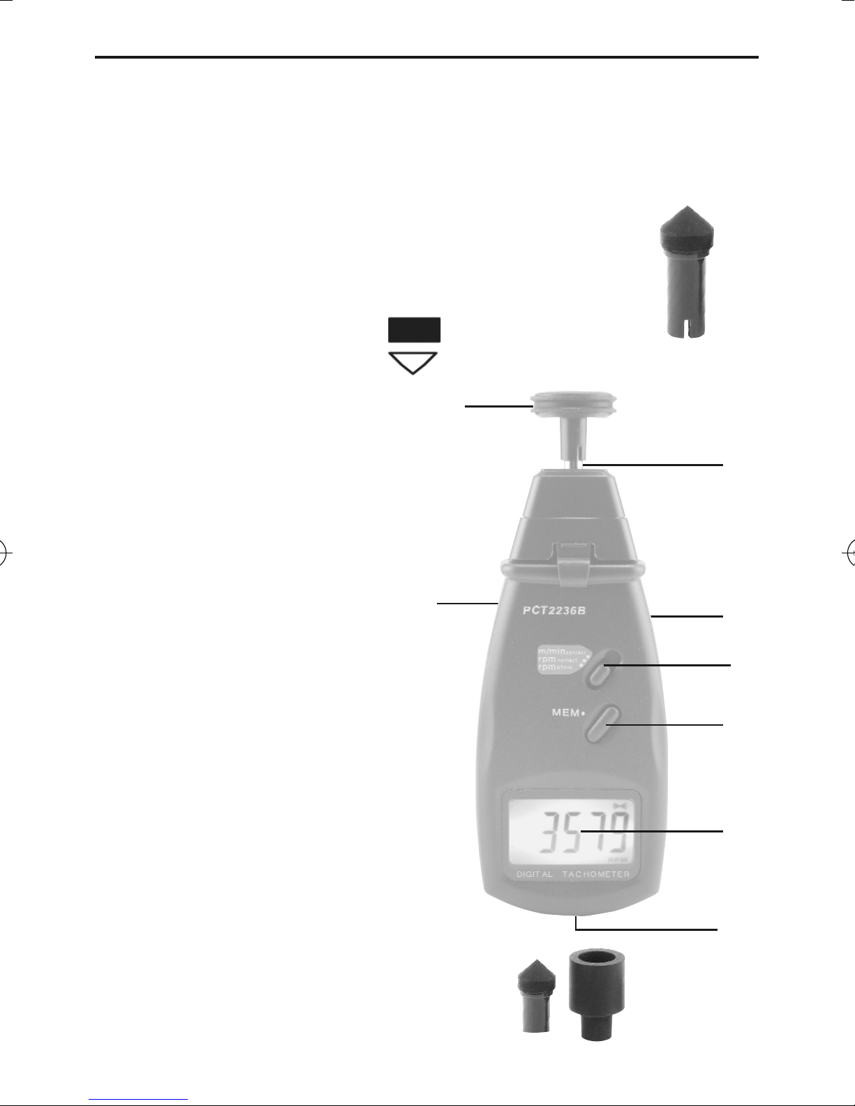
PRODUCT OVERVIEW
Figure 2 shows all of the controls and indicators and other
physical features of the PCT2236B. Familiarize yourself with
their names and locations before continuing.
A. Surface Speed Wheel
B. 1/2" Rubber RPM Adapter
(shown inserted
in plastic sleeve)
C. Tachometer Shaft
D.
Measurement
Button
(on right side)
E. Function Switch, labeled
“
m, m/min, rpm
”
F.
MEM
Button
G. Display Window
H. Battery Compartment Cover
(in back)
I. Jack for 6-V AC/DC Adapter
(on left side)
J. 1/4" Rubber RPM Adapter
K. 1/4" Rubber RPM Adapter
with hollowed end
L. Refelctive Tape (on spinning
motor or generator shaft)
M. Reflected Laser Light
(to internal photosensor)
Fig. 2. The PCT2236B’s
controls and indicators
and other physical features
6
SURFACE
SPEED WHEEL
C
D
E
F
G
H
K
J
I
B
L
M
A
Fig. 2
1/2" RPM ADAPTER
INSERTED IN BLACK
PLASTIC SLEEVE
Page 7

SETUP INSTRUCTIONS
INSTALL BATTERIES
To gain access to the battery compartment, remove the
Phillips head screw securing its cover in the back of the
instrument (callout H of Fig. 2). Slide the cover down and away
from the unit. Then install four “AA” batteries in the correct
orientation, using the polarity marks on the inside of the
compartment as a guide. Don’t forget to install the batteries
over the ribbon, which makes it easier to remove them later.
Replace the battery compartment cover, tucking the end of the
ribbon under it, and secure it with the Phillips head screw.
OPERATING INSTRUCTIONS
SIMULATE MAKING, STORING AND RECALLING RPM
MEASUREMENTS IN CONTACT MODE
Before using the PCT2236B on actual equipment, General
suggests that you familiarize yourself with the way the
instrument measures, stores and recalls speeds by spinning
the tachometer’s shaft by hand. By simulating readings you
can expect to see in practice, you will safely gain expertise
that will save you time later.
To get started, make sure the black plastic sleeve (see
Fig. 1 (B) ) is installed on the tachometer’s shaft (callout C of
Fig. 2), with the slot of the sleeve over the shaft’s metal pin.
Cradle the tachometer in your right hand. Move the function
switch (callout E of Fig. 2) to either the “
m/min
” or “
rpm
”
position. Then press the
Measurement button o
n the right
side of the instrument (callout D of Fig. 2) with your right
7
Page 8

thumb. Note that this illuminates the display window. The
display should show “0”, either with the letters “
rpm
” directly
below it or with the letters “
m/min
” below it to the left,
depending on the position of the function switch.
To simulate a speed measurement
, keep the tachometer
cradled in your right hand and spin its shaft by “flicking” it
with the middle two fingers on your left hand while pressing
the
Measurement button with your right thumb. Note how
the display tracks the force of yo
ur flicks, and also how the
instrument powers off whenever the
Measurement button
if released (this “dead man switch” feature extends batt
ery
life considerably).
To simulate storing measurements
, keep the
Measurement button dep
ressed with your right thumb while
you make three simulated speed measurements, as follows:
• Flick the shaft with your left index finger once. Store the
displayed reading by pressing the
MEM button w
ith your
left thumb.
• Flick the shaft again to make another simulated
measurement. Store this reading by pressing the
MEM
button
aga
in.
• Flick the shaft a third time and store the third reading as
well by pressing the
MEM button.
After simulating and storing three measurements, release
the
Measurement button
and do not press it again until
instructed to.
8
Page 9

To simulate recalling stored measurements
, press the
MEM
button once and hold it. This illuminates the display,
which now shows the highest of the three readings you have
just stored. Note that if you continue
holding the
MEM button,the display
alternates between showing the highest
value and the letters “
UP
”, signifying the
maximum speed.
Also note that releasing the
MEM button
pow
ers off the display and the instrument.
Now press the
MEM button twice and
hold it. This again illuminates the display,
but now it shows the last reading you stored, indicated by and
alternating with the letters “
LA
”.
Finally, press the
MEM button th
ree times and hold it. This
retrieves the slowest of the three speeds you measured and
stored. This value is shown alternating with the letters “
dn
”,
signifying the minimum speed.
To try out other memory-related features,
you can now press the
Measurement
button o
n the right side. Now press the
MEM button
once, twice and three times (holding it in each
time) and note from the display that all three of your stored
measurements have been erased (indicated by “
0.0
” readings
for
UP, dn
and
LA
). You can confirm this by pressing and holding
the
MEM button until
the display begins counting down from
20. When the count reaches 0, the display immediately switches
to showing the letters “
AN
” on the left side and a number (in
this case, “0”) on the right. (The letters “
AN
” are an
abbreviation for the Ancient Greek word for “recall.”)
9
Page 10

To complete this simulation exercise and put your new
expertise to the test, make and store a set of five simulated
measurements by hand-spinning the tachometer’s shaft and
using the
MEM button. Then
, remembering not to press the
Measurement button, press
and hold the
MEM button as
ma
ny times as needed to make the display go into countdown
mode.
Note that because you have stored five measurements, the
display will read “
AN 5
” once the countdown reaches zero. If
you release the
MEM
button and th
en press and hold it again,
the display will first read “1” and then the value of the first of
the five measurements you stored. If you release the
MEM
button
an
d then press and hold it again, the display will then
show “2”, followed by the value of your second measurement.
Release, press and hold again, and the display will show “3”,
followed by the value of your third measurement. By repeating
this sequence, you can retrieve up to 96 measurements in the
order in which they were stored. Once all of the stored
measurements have been displayed, the tachometer will
return to the mode in which pressing the
MEM
button once,
twice or three times calls up the minimum, maxim
um and
last values of the set of measurements you have stored.
With this simulated experience under your belt, you can now
confidently measure the rotational speed of a spinning motor or
generator shaft, or the linear speed of virtually any conveyor
belt.
10
Page 11

MEASURING ROTATING SPEEDS IN CONTACT MODE
To measure the speed of a rotating shaft
, first make sure
that the black plastic sleeve (see Fig. 1 (B) ) is installed on the
tachometer’s shaft (callout C of Fig. 2), with the slot of the
sleeve over the shaft’s metal pin. To measure the speed of a
motor’s or generator’s shaft with a hollowed (concave) end,
determine which of the two supplied cone-tipped rpm
adapters (see Fig. 1) fits more snugly in the hollow. Push the
flat end of that adapter into the end of the plastic sleeve. Then
slide the function switch on the front panel (callout E of Fig.2)
to the “
rpm
” position.
Cradle the tachometer in your right hand. While pressing the
Measurement
button on the right side of the instrument with
your right thumb, gently push the cone-tipped end of the rpm
adapter into the cavity at the end of the spinning motor or
generator shaft whose speed you wish to measure. Take care
to keep the two shafts aligned. When the displayed reading
has stabilized, and while keeping the
Measurement button
depressed with your right thumb, press the
MEM button
on
the front panel with your left thumb to store the measurement.
Make and store as many measurements as you wish, using
the lessons learned during the simulation exercise.
If the end of the shaft whose speed you want to measure is
flat or slightly convex and has a diameter of 0.25 in, locate the
rubber fitting with a 1/4 in. diameter hole at its wider end.
Insert the narrow end of this fitting into the black plastic
sleeve on the instrument’s shaft. Make sure the function
switch is set to “
rpm
”. Then, while cradling the tachometer in
your right hand, carefully push the other end of the fitting
11
Page 12

around the end of the motor or generator shaft. Take care to
line up the shafts of the equipment and the tachometer. Using
the
Measurement
and
MEM buttons
, make and store as
many readings of rotational speed as you wish.
MEASURING LINEAR SPEEDS
To measure the linear speed of a conveyor belt
, remove
the plastic sleeve and any rubber fitting inserted in it from the
tachometer’s metal shaft. Locate the surface speed wheel and
install it on the tachometer’s shaft, sliding the slot in the
wheel’s stem over the tachometer shaft’s metal pin.
Set the function switch to the “
m/min” position
. Then,
cradling the tachometer in your right hand, press the edge of
the surface wheel against the moving object whose linear
speed you wish to measure. Note that the circumference of
the wheel has a 1/8-in.-wide slot into which wire, cable or
rope of that diameter fits snugly.
Taking care to keep the tachometer perpendicular to the
moving conveyor, use the function and
MEM buttons
to make
and store as many measurements of linear speed as you wish.
Linear speed measurements of moving objects obtained by
placing them in contact with the outer diameter of the surface
speed measurements are accurate as displayed. However, to
compensate for the smaller inner diameter of the wheel within
its slot, measurements made by placing wire, cable or rope
within the slot should be multiplied by 0.9.
MEASURING SURFACE DIMENSIONS
The PCT2236B can also serve as a metric ruler. To operate it in
that mode, move the function switch to the “m” position and
12
Page 13

install the surface speed wheel directly onto the instrument’s
metal shaft.
Cradling the tachometer in your right hand and pressing and
holding the
Measurement button
, roll the wheel across
the length, width or depth of the object you wish to measure.
The displayed value represents the dimension measured, in
meters. Measurements made in this mode of operation cannot
be stored, and disappear from the display when the
Measurement button
is released.
MAKING RPM MEASUREMENTS IN
NON-CONTACT MODE
To use the PCT2236B to make non-contact rpm
measurements, you must first remove the black plastic
housing at the top of the instrument that covers the laser light
source and lens.
To prepare to remove the housing, first remove the black
plastic sleeve and any rpm adapter attached to it (callout B of
Fig. 2) from the tachometer’s shaft (callout C). Then remove
the Phillips head screw securing the housing via a flange to
the back of the tachometer. Next, carefully lift both plastic
flanges (front and back) that keep the housing in place. Once
you have unsnapped the housing, pull it up and over the
tachometer’s shaft and place it to one side. Note that when
you now press the
Measurement
button, a red laser light
shines out of the top of the PCT2236B.
13
Page 14

Caution
: The Phillips head screws securing both the housing
and the battery compartment cover are not equipped with
retainers, so they are easy to lose. The PCT2236B includes
three spare screws designed to serve both purposes.
To measure the rotational speed of a motor/generator shaft:
1. Identify the target.
Determine whether there is a larger
surface to measure than the shaft itself. If some thing with a
larger diameter (for example, a fan or a wheel of any type)
is attached to the shaft, use any flat part of its surface as
the measurement target instead.
2. Prepare the target.
Either unplug the generator/motor or
make sure that it cannot be turned on remotely or turn on
automatically. Scrape the target area clean enough so a
piece of tape will stick to it. If the target area is naturally
reflective, cover it with black tape or paint.
3. Attach reflective tape to the target.
Cut a 1/2 in. square
piece of reflective tape, remove its backing, and apply it to
the target area.
4. Make the measurement.
Turn on the motor or generator.
Cradling the tachometer in your right hand, move it as close
to the shaft as possible, but no closer than 2 inches away.
Position the instrument so its main axis is aligned with the
end of the shaft. Using your right thumb, press the Measure
button (callout 1-4) while shining the red laser beam on the
reflective tape. Confirm that the tachometer is receiving a
signal by checking that the (( )) Monitor Indicator icon flashes
on the display each time the beam hits the moving tape.
When the display reading stabilizes, release the Measure
button.
14
Page 15

STORING AND RECALLING RPM
MEASUREMENTS IN NON-CONTACT MODE
To store and recall non-contact rpm measurements, use the
same procedures for contact rpm measurements that you
simulated beginning on p. 8.
As in contact measurement mode, in non-contact mode
individual measurements or series of measurements can only
be stored while the
Measurement
button is pressed and held.
When the
Measurement
button is released, the contents of
the instrument’s memory are frozen. When the
Measurement
button is pressed again, the memory’s contents are erased.
15
TWO MEASUREMENT TIPS
1. If your motor/generator’s shaft spins slowly
(i.e., at
less than 50 rpm), getting an accurate reading may
require placing one or more additional squares of
reflective tape on the target. Begin by adding a second
square of tape on the circumference of the target 180º
from the first square (at 6 o’clock relative to 12
o’clock). Then perform Step 4 above, but divide the
display reading by two to account for the presence of
the second square. If the result is still unsatisfactory,
add another two pieces of tape at 3 o’clock and 9
o’clock and perform Step 4, but now divide the display
reading by four.
2. If bright ambient light is preventing the PCT2236B
from receiving the reflected beam, try shading the target.
Page 16

SPECIFICATIONS
Parameter Specification— Specification—
Contact Mode Non-contact mode
Rotational Speed 0 to 20,000 rpm/±0.05% 2.5 to 99,999 rpm/±0.05% of
Measurement Range/Accuracy of reading plus one digit reading plus one digit
Rotational Speed 0.1 rpm for readings below 999.9 rpm; 1 rpm for readings above
Measurement Resolution 1,000 rpm
Linear Speed 5cm/min (2 in./min) N/A
Measurement Range to 2km/min (6,562 ft./min)
Length Measurement Range 5cm to 10km (2 in. to 6.2 miles) N/A
Detection Distance N/A 5 to 50cm (2 to 20 in.)
Sampling Time 0.8 seconds at speeds over 60 rpm
Memory Capacity 96 measurements
Recallable Measurements Maximum, minimum, last values
Page 17

17
SPECIFICATIONS (continued)
Parameter Specification
Microcontroller Single custom chip
Time Base Quartz crystal
Display Type 5-digit yellow-green backlit liquid crystal
Display Height 0.7 in. (18mm)
Dimensions 8.27 x 2.91 x 1.18 in. (210 x 74 x 30mm)
Weight 7.76 oz. (220g), including batteries
Power Source Four “AA” batteries
Current Consumption 65mADC
Operating Temperature Range 32º to 122ºF (0º to 50ºC) @ up to 80% relative humidity
Page 18

MAINTENANCE TIPS
The PCT2236B requires no regular maintenance other than
light cleaning of the housing and display with a soft, dry cloth.
When the text “
LO
” appears on the display, it’s time to change
the PCT2236B’s four “AA” batteries because their total
potential has fallen below 4.5 volts. To do so, follow the Setup
Instructions on p. 7.
Remove the batteries whenever the instrument is expected to
sit idle for an extended period of time (six months or more).
WARRANTY INFORMATION
General Tools & Instruments’ (General’s) PCT2236B
Combination Contact/ Non-Contact Laser Tachometer is
warranted to the original purchaser to be free from defects in
material and workmanship for a period of one year. Subject to
certain restrictions, General will repair or replace this
instrument if, after examination, the company determines it to
be defective in material or workmanship.
This warranty does not apply to damages that General
determines to be from an attempted repair by non-authorized
personnel or misuse, alterations, normal wear and tear, or
accidental damage. The defective unit must be returned to
General Tools & Instruments or to a General-authorized service
center, freight prepaid and insured.
Acceptance of the exclusive repair and replacement remedies
described herein is a condition of the contract for purchase of
this product. In no event shall General be liable for any
incidental, special, consequential or punitive damages,
18
Page 19

or for any cost, attorneys’ fees, expenses, or losses alleged to
be a consequence of any damage due to failure of, or defect in
this product including, but not limited to, any claims for loss of
profits.
RETURN FOR REPAIR POLICY
Every effort has been made to provide you with a reliable
product of superior quality. However, in the event your
instrument requires repair, please contact our Customer
Service to obtain an RGA (Return Goods Authorization) number
before forwarding the unit via prepaid freight to the attention
of our Service Center at this address:
General Tools & Instruments
80 White Street
New York, NY 10013
212-431-6100
Remember to include a copy of your proof of purchase, your
return address, and your phone number and/or e-mail
address.
19
Page 20

GENERAL TOOLS & INSTRUMENTS
80 White Street
New York, NY 10013-3567
PHONE (212) 431-6100
FAX (212) 431-6499
TOLL FREE (800) 697-8665
e-mail: sales@generaltools.com
www.generaltools.com
PCT2236B User’s Manual
Specifications subject to change without notice
©2011 GENERAL TOOLS & INSTRUMENTS
NOTICE - WE ARE NOT RESPONSIBLE
FOR TYPOGRAPHICAL ERRORS.
MAN#PCT2236B 3/22/11
 Loading...