

Page 1
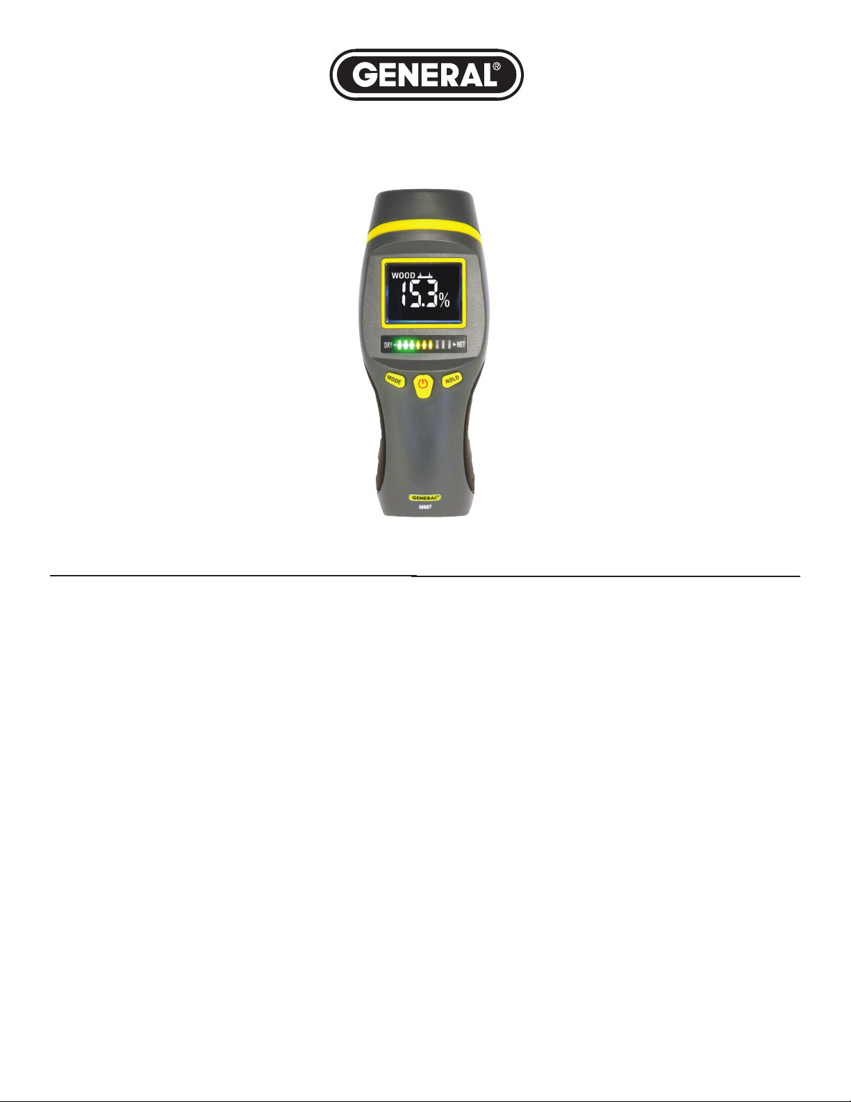
PIN-TYPE LCD MOISTURE METER
WITH TRICOLOR BAR GRAPH
USER’S MANUAL
MM7
ul
ase read
e
Pl
these
ons care
ti
uc
nstr
i
INTRODUCTION
Thank you for purchasing General Tools & Instruments’ MM7
Pin-Type LCD Moisture Meter with Tricolor Bar Graph. Please
read this user’s manual carefully and thoroughly before using
the instrument.
The MM7 is designed for use in woodworking, water damage
restoration, building construction and home renovation.
Examples include:
• Checking for moisture and mold on or below the surface of
carpets and subflooring
• Measuring the moisture content of wood, drywall or cement
board before painting, wallpapering, sealing or treating
• Locating water leaks above ceilings, below floors or behind
walls
• Selecting dry lumber
The MM7 bases its measurements on the relationship between
the moisture content of a material and its electrical conductivity.
The wetter a material, the higher its conductivity.
The two replaceable steel pins at the top of the MM7 serve as
the electrodes of a conductance meter optimized for measuring
moisture content. The meter displays measurements in the unit
%WME (Wood Moisture Equivalent).
For hard materials like wood, the meter’s readings largely reflect
surface moisture content because: 1) Moisture close to a surface
has a greater effect on a reading than moisture deep below it;
and 2) The pins of the MM7 are only 0.3 in. (8mm) long and
f
y an
l
thorou
d
ghl
t.
uc
rod
p
e
g th
n
ore usi
f
e
y b
therefore cannot be driven deep into a hard material. For softer
materials like soil, paper or powders, readings are more likely to
reflect the average moisture level of the material between its
surface and the penetration depth of the pins (normally far less
than 0.3 in.).
The MODE button on the front panel provides a convenient way
to switch between testing wood and building materials. When
the MM7 is powered on, it automatically enters wood
measurement mode.
Below the LCD is a analog bar graph comprising three banks of
different-colored LEDs. The LEDs light up in sync with changes
in the digital readout.
As the test pins are moved around a sample, or moved among
samples, the color of the right-most “lit” LED (green, orange or
red) may change. Any such change indicates a sizable difference
in the moisture content of different areas of the same sample, or
of different samples of wood or building material.
See the Specifications table on page 3 for the different moisture
ranges of wood and building materials indicated by the three
LED bar graph bands.
To extend battery life in both operating modes, the MM7
automatically 1) dims the brightness of its backlit LCD by
one-half after 15 seconds and 2) powers itself off after 1 minute
of inactivity.
The instrument is powered by a “9V”battery (included in the
package).
1
Page 2

PRODUCT OVERVIEW
ig. 1 shows all of the controls, indicators and physical features
F
of the MM7. Fig. 2 shows all possible display indications.
Familiarize yourself with the position and function of all
components before moving on to the Setup Instructions
and Operating Instructions.
Fig. 1.
The controls, indicators and physical features of the MM7
Fig 2. All possible display indications
A. Moisture level readout
B. Indicates operation in wood measurement mode
C. Indicates operation in pin mode
D. Indicates operation in building material measurement mode
E. Low battery charge indication; replace the “9V” battery when
it appears
F. Indicates a held measurement
G. Moisture measurement unit (%WME)
SETUP INSTRUCTIONS
INSTALL BATTERY
Open the battery compartment at the bottom of the meter
(Fig. 1, Callout J) by placing a fingernail in the slot on the right
side of the housing where it meets the compartment door. Push
the tab on the door gently to the left until it pops open. Remove
the “9V” battery from the packaging and slide it into the
compartment “terminals-first”, with the anode (+ terminal) on
the right, as indicated by the markings inside the compartment.
Swing the door back toward its closed position until it snaps
shut.
A. Removable pin cover with fixed calibration-checking resistor
on its underside
B. High-contrast, white-on-black LCD (see Fig. 2)
C. LED bar graph; mirrors reading on LCD
D.
HOLD
button. “Freezes” and releases LCD and LED readouts.
Also used to enable and silence out-of-range alarms.
E. button.
and held
F.
MODE
measurement of wood or building material.
G. Calibration holes sized for the MM7's measurement pins
H. Measurement pin covers
I. Measurement pins
J. Battery compartment
Pressed briefly
for at least 3 seconds, powers the meter off.
button.
Pressed briefly, selects WME% moisture
, powers the meter on.
Pressed
OPERATING INSTRUCTIONS
To power on the meter, press and hold the
Callout E)
follow the same instruction.)
To measure the moisture level of wood or a building material,
power on the meter and remove the pin cover (Fig. 1, Callout A)
by squeezing it gently to pop it off. The LCD will display the word
WOOD
right. Remove the black rubber insulating sleeves from the pins.
To measure wood
Its absolute moisture level will be displayed as a percentage,
with the unit %WME (Fig. 2, Callouts A and G). Simultaneously,
the bar graph LEDs will illuminate to mirror the digital reading.
To measure a building material, press the MODE button to
change the indication on the top line of the LCD from
BLDG
pins into the sample. Its absolute moisture level will be displayed
as a percentage, with the unit %WME. Again, one or more bar
graph LEDs will illuminate to mirror the digital reading.
In wood measurement mode, the available moisture level range
is 5% to 50%. When the level is below 5%, the LCD will show
__ __ __. When it is above 50%, the LCD will show  ̄ ̄ ̄.
In building material measurement mode, the available moisture
level range is 1.5% to 33%. When the level is below 1.5%, the
LCD will show __ __ __. When it is above 33%, the LCD will
show
2
for at least three seconds. (To power off the meter,
(Fig. 2, Callout B) and the pin-mode icon (Callout C) at its
, carefully press the test pins into the sample.
(Fig. 2, Callout D). As with wood, carefully press the test
 ̄ ̄ ̄
.
button (Fig. 1,
WOOD
to
Page 3

Whenever a test sample is determined to be "wet" (above 16%
moisture content for wood, or above 20% for a building
aterial), one or more red LEDs will illuminate and the meter
m
will produce an audible alarm. The alarm will continue to sound
until the test pins are removed from the sample, or moved to a
drier area.
To silence the excessive-moisture alarm or re-enable it,
press and hold the HOLD button for at least three seconds.
To hold a digital reading
, briefly press the HOLD button within
one minute of making the measurement. The LCD will add the
HOLD
word
to the digital reading, and the bar graph LEDs will
“freeze” in their current state (illuminated or not).
MEASUREMENT TIPS
Ideally, your test sample should be at least 3/8 in. thick. That is
the thickness for which the meter is calibrated. If your sample is
too thin, readings may be inaccurate.
Measurements of wood are skewed by two variables: ambient
humidity and the density of the wood species. The best way to
compensate for the effect of these variables is to develop your
own moisture level curves, based on your experience working
with different species of wood on a day-to-day basis.
LED Bands (continued)
uto Power Off Trigger 1 minute of inactivity
A
Low Battery Icon Trigger <7V
Operating Temperature 32° to 104°F (0° to 40°C)
Storage Temperature 14° to 122°F (-10° to 50°C)
Dimensions 6.9 x 2.8 x 2.9 in. (174 x 70 x 74mm)
Weight 5.3 oz. (150g) without battery
Power Source (1) “9V” battery (included)
In building material mode, only green
LEDs indicate that a test area's moisture
ontent is between 1.5% and 16.9%
c
(dry). When only green and orange LEDs
are lit, the area has a moisture content of
17% to 19.9% (medium moisture
content). When green, orange and red
EDs are lit, the area has a moisture
L
content between 20% and 33% (wet).
Replacement Test Pins Available
The MM7’s stainless steel pins are
replaceable. General’s Item #PIN3
contains two pairs of compatible pins,
each 0.3 in. (8mm) long.
CALIBRATING THE METER
Although the MM7 auto-calibrates each time it is powered on,
you can manually check its calibration. Perform a calibration
check whenever the meter cannot produce a reading, or if
multiple measurements of the same sample produce very
different readings.
To manually check calibration, power the meter on and open
and remove the pin cover (Fig. 1, Callout A). Flip the cover over
and insert the test pins into the calibration holes (Fig. 1, Callout
G) through the top of the cover. The LCD should show a value
between 17.3% and 19.3%. If the reading is outside
this range, the MM7 has an accuracy problem. Contact General's
Customer Service to arrange for a replacement.
SPECIFICATIONS
Measurement Ranges 5 to 50% for wood
1.5 to 33% for building materials
Measurement Accuracy ±2% for wood and building material
Measurement Resolution 0.1%
Calibration Check Range 17.3% to 19.3%
Out-of-Range Alarm Levels >16% for wood
>20% for building materials
LCD Size
Bar Graph Composition 3 each green, orange and red LEDs
LED Bands In wood mode, only green LEDs indicate
2 in. (51mm) diagonal, with
three 0.5 in. (13mm) high digits
that a test area’s moisture content is
between 5% and 11.9% (dry). When only
green and orange LEDs are lit, the area
has a moisture content of 12% to 15.9%
(medium moisture content). When green,
orange and red LEDs are lit, the area has
a moisture content between 16% and
50% (wet).
WARRANTY INFORMATION
In the U.S, General warrants its instruments and accessories, and
digital tools against defects in material or workmanship for one year
from the date of purchase unless otherwise stated on the packaging,
manual, and/or marketing materials. General also warrants its nondigital tools products against defects in material or workmanship on
a limited lifetime term. The company will replace or repair the
defective unit, at its option, subject to verification of the defect.
This warranty does not apply to defects resulting from abuse, neglect,
accident, unauthorized repair, alteration, or unreasonable use of the
product.
Any implied warranties arising from the sale of a General product,
including but not limited to implied warranties of merchantability and
fitness for a particular purpose, are limited to the above. General shall
not be liable for loss of use of the product or other incidental or
consequential damages, expenses, or economic loss, or for any claim
of such damage, expenses, or economic loss.
State laws vary. The above limitations or exclusions may not apply
to you.
RETURN FOR WARRANTY CLAIM
Every effort has been made to provide you with a reliable product of
superior quality. To make a warranty claim, please contact our
Customer Service to obtain an RGA (Return Goods Authorization)
number before forwarding the unit via prepaid freight
to the attention of our Service Center at this address:
General Tools & Instruments
75 Seaview Drive
Secaucus, NJ 07094
212-431-6100
Remember to include a copy of your proof of purchase, your return
address, and your phone number and/or e-mail address.
3
 Loading...