

Page 1

DCT 1000
Cable Terminal
Installation Manual
MENUINFOCURSORGUIDE SELECT BYPASS CHANNEL
POWER
Page 2

Graphical symbols and supplement warning marking locations on the bottom of the appliance.
This symbol means that dangerous voltage levels are present within the equipment. These voltages are not
insulated, and may be of sufficient strength to cause serious bodily injury if touched. The symbol may also appear
on schematics.
This symbol calls attention to a critical procedure, or means refer to the instruction manual for opening or service
information. Only qualified service personnel are to install or service the equipment. The symbol may also appear
in text and on schematics.
WARNING:
TO PREVENT FIRE OR SHOCK HAZARD, DO NOT EXPOSE THIS APPLIANCE TO RAIN OR MOISTURE.
CAUTION:
TO PREVENT ELECTRICAL SHOCK, DO NOT USE THIS (POLARIZED) PLUG WITH AN EXTENSION CORD,
RECEPTACLE, OR OTHER OUTLET UNLESS THE BLADES CAN BE FULLY INSERTED TO PREVENT BLADE EXPOSURE.
FCC Compliance: This equipment has been tested and found to comply with the limits for a Class B digital device, pursuant to Part 15 of the
FCC Rules. These limits are designed to provide reasonable protection against harmful interference when the equipment is operated in a
commercial environment. This equipment generates, uses, and can radiate radio frequency energy and, if not installed and used in accordance
with the Installation Manual, may cause harmful interference to radio communications. Operation of this equipment in a residential area is likely
to cause harmful interference in which case the user will be required to correct the interference at his own expense. Any changes or
modifications not expressly approved by General Instrument could void the user’s authority to operate this equipment under the rules and
regulations of the FCC.
Canadian Compliance: This Class B digital apparatus meets all requirements of he Canadian Interference-Causing Equipment Regulations.
Cet appareil numérique de la classe A respects toutes les exigences du Règlement sur le matériel brouilleur du Canada.
Repairs: If repair is necessary, call the General Instrument Repair Facility at 1-800-227-0450 for a Return for Service Authorization (RSA)
number before sending the unit. The RSA number must be prominently displayed on all equipment cartons. Pack the unit securely, enclose a
note describing the exact problem, and a copy of the invoice that verifies the warranty status. Ship the unit PRE-PAID to the following address:
GI Communications
4694 Coffee Port Road
Brownsville, TX 78521
Attn: RSA #___________
NOTE TO CATV SYSTEM INSTALLER: This reminder is provided to call CATV system installer’s attention to Article 820-40 of the NEC that
provides guidelines for proper grounding and, in particular, specifies that the cable ground shall be connected to the grounding system of the
building, as close as possible to the point of cable entry as practical.
Copyright © 1996 by General Instrument Corporation.
All rights reserved. No part of this publication may be reproduced in any form or by any means or used to make any derivative work (such as
translation, transformation or adaptation) without written permission from General Instrument.
General Instrument reserves the right to revise this publication and to make changes in content from time to time without obligation on the part of
General Instrument to provide notification of such revision or change. General Instrument provides this guide without warranty of any kind, either
implied or expressed, including, but not limited, to the implied warranties of merchantability and fitness for a particular purpose. General
Instrument may make improvements or changes in the product(s) described in this manual at any time.
STARFONE and STARVUE II are registered trademarks of General Instrument Corporation.
Music Choice is a trademark of General Instrument Corporation.
TV Guide on Screen, Flip, Browse, Reminder, Lockout, and Channel Manager are trademarks of TV Guide Financial, Inc.
Page 3

Table of Contents
Section 1 Introduction
Features and Options ................................................................................................. 1-1
Using This Manual ...................................................................................................... 1-2
Related Documentation .............................................................................................. 1-3
If You Need Help ......................................................................................................... 1-3
Calling for Repairs ...................................................................................................... 1-3
Section 2 Overview
Front Panel Controls and Displays ............................................................................ 2-1
Rear Panel Connectors ............................................................................................... 2-3
Configuration Options ................................................................................................ 2-5
Remote Controls ......................................................................................................... 2-6
XRC 100 Remote Control ........................................................................................ 2-7
Installing Batteries in Remote Control ...................................................................... 2-7
Section 3 Installation
Before You Begin ........................................................................................................ 3-1
Installing the DCT 1000 ............................................................................................... 3-1
General Configuration Instructions .......................................................................... 3-2
Standard Wiring Cabling Diagrams .......................................................................... 3-2
A/B Switch-out Cabling Diagrams ............................................................................ 3-4
A/B Switch-in Cabling Diagrams .............................................................................. 3-6
Operational Check ...................................................................................................... 3-8
Troubleshooting ...................................................................................................... 3-9
Section 4 Adding a VCR or Stereo Component
Standard VCR Cabling Diagram ................................................................................. 4-1
RF Bypass Switch VCR Cabling Diagrams ................................................................ 4-2
A/B Switch-Out VCR Cabling Diagram ....................................................................... 4-4
A/B Switch-In VCR Cabling Diagram ......................................................................... 4-5
Composite (Baseband) VCR Cabling Diagram .......................................................... 4-6
Stereo System Cabling Diagram ................................................................................ 4-7
DCT1000 Installation Manual
Page 4

ii Table of Contents
Section 5 TV Guide On Screen
Remote Control ............................................................................................................ 5-1
XRC 200 Remote Control ........................................................................................ 5-2
Installing Batteries in Remote Control ...................................................................... 5-2
Quick Tips for the Program Guide .............................................................................. 5-3
Setting Up the Program Guide .................................................................................... 5-3
Confirm Proper Installation ...................................................................................... 5-4
Configure TV Guide On Screen ............................................................................... 5-5
Getting Started with the Program Guide .................................................................... 5-7
Flip .......................................................................................................................... 5-7
Browse .................................................................................................................... 5-7
Listing Menus .......................................................................................................... 5-7
Pay-Per-View .......................................................................................................... 5-7
Messages ................................................................................................................ 5-8
Lockout ................................................................................................................... 5-8
Channel Manager .................................................................................................... 5-8
Timers ..................................................................................................................... 5-8
Help ........................................................................................................................ 5-9
Appendix A Specifications
Appendix B Diagnostics
Accessing Diagnostics ................................................................................................ B-1
Summary of Diagnostic Modes ................................................................................... B-2
d 01: DCT 1000 General Status .............................................................................. B-3
d 02: Out-Of-Band Receiver Status ........................................................................ B-4
Carrier Lock ...................................................................................................... B-5
Packet/Frame Sync ........................................................................................... B-5
Data Activity ...................................................................................................... B-6
EMM Data Activity ............................................................................................. B-6
d 03: In-Band Receiver Status ................................................................................ B-6
Carrier Lock ...................................................................................................... B-7
Reed-Solomon Sync ......................................................................................... B-7
Packet/Frame Sync ........................................................................................... B-7
Adaptive Equalizer Stress ................................................................................. B-8
Data Activity ...................................................................................................... B-8
EMM Data Activity ............................................................................................. B-8
d 04: QAM Receiver Short-Term Error Rate ........................................................... B-8
d 05: QAM Receiver Long-Term Error Rate ............................................................ B-9
d 06: Unit Address .................................................................................................. B-10
DCT1000 Installation Manual
Page 5

Table of Contents iii
d 07: Unit Serial Number ........................................................................................ B-11
d 08: Dena Firmware Version ................................................................................. B-12
d 09: Current-Channel Status ................................................................................. B-13
Decryptor Status Modes ................................................................................... B-14
Purchasable Status ........................................................................................... B-14
d 10: Renewable Security System .......................................................................... B-15
TvPC Required ................................................................................................. B-15
Current Mode .................................................................................................... B-16
TvPC Status ..................................................................................................... B-16
d 11: Upstream Modem Status ............................................................................... B-16
STARVUE II Diagnostics .................................................................................. B-17
STARFONE Diagnostics ................................................................................... B-18
d 12: Application Code Modules ............................................................................. B-20
d 13: Application Expansion Modules ..................................................................... B-20
d 14: Memory Status .............................................................................................. B-21
Figures
Figure 1-1 Front view of the DCT 1000 cable terminal ................................................. 1-2
Figure 1-2 Rear view of the DCT 1000 cable terminal ................................................. 1-2
Figure 2-1 DCT 1000 cable terminal front panel ........................................................... 2-1
Figure 2-2 DCT 1000 cable terminal rear panel ............................................................ 2-3
Figure 2-3 DCT 1000 options ....................................................................................... 2-5
Figure 2-4 XRC 100 remote control .............................................................................. 2-7
Figure 3-1 Standard wiring without a PPV module ........................................................ 3-2
Figure 3-2 Standard wiring with a STARVUE II module ................................................ 3-3
Figure 3-3 Standard wiring with a STARFONE module ................................................ 3-3
Figure 3-4 A/B switch-out without a PPV module ......................................................... 3-4
Figure 3-5 A/B switch-out with a STARVUE II module .................................................. 3-5
Figure 3-6 A/B switch-out with a STARFONE module .................................................. 3-5
Figure 3-7 A/B switch-in without a PPV module ............................................................ 3-6
Figure 3-8 A/B switch-in with a STARVUE II module and the return on cable A
.................................................................................................................... 3-7
Figure 3-9 A/B switch-in with a STARVUE II module and the return on cable B
.................................................................................................................... 3-7
Figure 3-10 A/B switch-in with a STARFONE module .................................................... 3-8
Figure 4-1 Standard VCR cabling ................................................................................. 4-1
Figure 4-2 RF Bypass switch with VCR ........................................................................ 4-2
Figure 4-3 RF Bypass switch with VCR and STARVUE II module ................................ 4-3
Figure 4-4 A/B switch-out with VCR ............................................................................. 4-4
Figure 4-5 A/B switch-in with VCR ............................................................................... 4-5
DCT1000 Installation Manual
Page 6

iv Table of Contents
Figure 4-6 Composite VCR Cabling .............................................................................. 4-6
Figure 4-7 Stereo system cabling ................................................................................. 4-7
Figure 5-1 XRC 200 remote control .............................................................................. 5-2
Figure 5-2 Notice screen .............................................................................................. 5-3
Figure 5-3 Setup screen, with Cable Terminal selected ................................................ 5-4
Figure 5-4 Cable terminal setup screen ........................................................................ 5-4
Figure 5-5 Configuration screen .................................................................................... 5-5
Figure 5-6 Setup screen, with TV Guide On Screen selected ........................................ 5-6
Figure 5-7 TV Guide On Screen Setup ......................................................................... 5-6
Figure B-1 Diagnostics selection OSD display data ....................................................... B-2
Figure B-2 General status LED display ......................................................................... B-3
Figure B-3 General status OSD display data ................................................................. B-3
Figure B-4 Out-of band status LED display ................................................................... B-4
Figure B-5 Out-of-band status OSD display data ........................................................... B-5
Figure B-6 LED indication of no data received ............................................................... B-5
Figure B-7 In-band receiver digital status LED display ................................................... B-6
Figure B-8 In-band receiver digital status OSD display data .......................................... B-7
Figure B-9 Receiver short-term error rate LED display .................................................. B-8
Figure B-10 Receiver short-term error rate OSD display data .......................................... B-9
Figure B-11 Receiver long-term error rate LED display ................................................... B-9
Figure B-12 Receiver long-term error rate OSD display data ........................................... B-10
Figure B-13 Unit address LED display ............................................................................. B-11
Figure B-14 Unit address OSD display data .................................................................... B-11
Figure B-15 Unit serial number LED display .................................................................... B-12
Figure B-16 Unit serial number OSD display data ........................................................... B-12
Figure B-17 Dena firmware version LED display ............................................................. B-12
Figure B-18 Dena firmware version OSD display data ..................................................... B-13
Figure B-19 Decryptor status LED display ....................................................................... B-13
Figure B-20 Decryptor status OSD display data .............................................................. B-14
Figure B-21 Renewable security status LED display ....................................................... B-15
Figure B-22 Renewable security status OSD display data ............................................... B-15
Figure B-23 STARVUE II diagnostics LED display .......................................................... B-17
Figure B-24 STARVUE II diagnostics OSD display data .................................................. B-17
Figure B-25 STARFONE diagnostics LED display ........................................................... B-18
Figure B-26 STARFONE diagnostics OSD display data .................................................. B-18
Figure B-27 Application code modules OSD display data ................................................ B-20
Figure B-28 Application expansion modules OSD display data ........................................ B-20
Figure B-29 Memory status OSD display data ................................................................. B-21
DCT1000 Installation Manual
Page 7

Section 1
Introduction
The DCT 1000 is an analog/digital cable terminal designed to be configurable and upgradeable to
meet the future needs of emerging technologies in the communications industry. The base unit
supports numerous configurations. This manual provides instructions on installing the base
unit and the following options:
n
A/B Switch-out
n
A/B Switch-in
n
RF Bypass Switch
n
STARVUE II Module
n
STARFONE Module
The DCT 1000 operates in the same system with existing analog set-top terminal products.
Existing set-tops are not affected by the new information flowing from the system to the
DCT 1000 cable terminals.
Features and Options
The General Instrument DCT 1000 cable terminal offers the following standard features:
n
54 to 860 MHz integrated tuner
n
RF, video, and audio ports
n
IR Blaster port
n
Data output port
n
Application interface port
n
Switched accessory outlet
Among the optional features available are:
n
STARVUE II and STARFONE modules
n
RF Bypass switch
n
A/B Switch-in
n
A/B Switch-out
n
Audio loop-thru
n
High and low power IR Blaster modules
DCT1000 Installation Manual
Page 8
1-2 Introduction
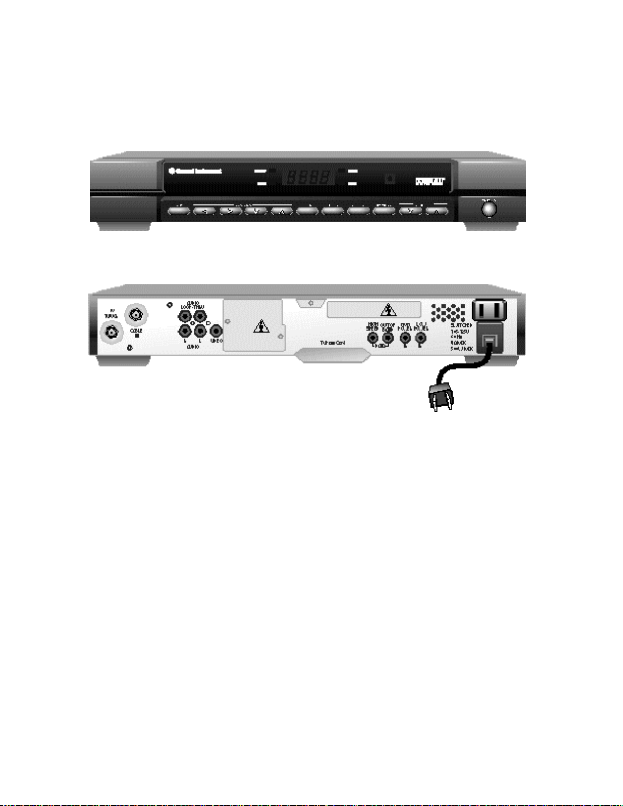
The following illustrations show the front and rear views of the standard unit:
Figure 1-1
Front view of the DCT 1000 cable terminal
Figure 1-2
Rear view of the DCT 1000 cable terminal
Using This Manual
This manual provides instructions for the following tasks necessary to install and configure a
DCT 1000 cable terminal.
Section 1
Section 2
Section 3
Section 4
Section 5
Appendix A
Appendix B
Provides a brief introduction to the product, identifies the information contained in this
manual, lists related documentation, and gives the helpline telephone number and return
procedure.
Describes the DCT 1000 cable terminal and provides an overview of its use. This section
also identifies the front panel displays and switches, and describes the rear panel
connectors.
Provides instructions on how to install a DCT 1000 cable terminal in a subscriber location
and perform operational tests.
Provides instructions on how to connect a VCR or stereo equipment to a DCT 1000 cable
terminal in a subscriber location.
Provides instructions on checking-out operation of TV Guide On Screen (an optional
electronic program guide), and on a few basic operations so that you can introduce your
subscriber to the guide.
Lists technical specifications for the DCT 1000 cable terminal.
Provides instructions on accessing and interpreting the built-in diagnostics.
DCT1000 Installation Manual
Page 9

Introduction 1-3
Related Documentation
Separate instruction manuals are available for associated components. Although these may be
of interest to you, they are not necessary to install or operate the basic DCT 1000 cable terminal.
n
DCT 1000 User Guide, part number 437-011-400
n
XRC 100 Remote Control User Guide, part number 437-053-400
n
A/B In Switch Installation Instructions, part number 437-043-200
n
A/B Out Switch Installation Instructions, part number 437-044-200
n
Starfone Installation Instructions, part number 436-420-202
n
Starvue II Installation Instructions, not yet released
If You Need Help
If you need assistance while working with the DCT 1000 cable terminal, call the General
Instrument Technical Response Center at 1-800-537-7653. The Technical Response Center is
open from 7:30 a.m. to 9:00 p.m. Eastern Standard Time, Monday through Friday. When the
Technical Response Center is closed, emergency service only is available on a call-back basis.
If calling from outside the United States, please use our main switchboard number,
1-215-674-4800, when contacting the Technical Response Center.
Calling for Repairs
If repair is necessary, call the General Instrument Repair Facility at 1-800-227-0450 for a
Return for Service Authorization (RSA) number before sending the unit. The RSA number must
be prominently displayed on all equipment cartons. The Repair Facility is open from 8:00 a.m.
to 5:00 p.m. Central Standard Time, Monday through Friday.
If calling from outside the United States, dial your appropriate international access code, then
dial 52-891-40739, to contact the Repair Facility.
When shipping equipment for repair, follow these steps:
Pack the unit securely.
1 Enclose a note describing the exact problem.
2 Enclose a copy of the invoice that verifies the warranty status.
3 Ship the unit PRE-PAID to the following address:
GI Communications
4694 Coffee Port Road
Brownsville, TX 78521
Attn: RSA #___________
DCT1000 Installation Manual
Page 10

Section 2
Overview
In this section you will find illustrations and tables showing the features of the front and rear
panels of the DCT 1000 cable terminal. Before beginning the installation process, please take
the time to familiarize yourself with the various controls and displays.
Front Panel Controls and Displays
The front panel, illustrated below, contains selection buttons, tuning buttons, various displays,
and the power switch. These controls are designed to provide a minimum, but functional,
capability in the event that the cable terminal remote control is lost or is temporarily out of
service. However, certain functions (for example, those requiring numeric entry) are not
available without a remote control.
Figure 2-1
DCT 1000 cable terminal front panel
See the following table for an explanation of the controls accessible from the front panel (A
through H) and a description of the LEDs (I through M).
DCT1000 Installation Manual
Page 11

2-2 Overview
Key Connector Function
A
B
C
D
E
F
G
H
I
Turns terminal on/off.
Change channel up and down.
Operates the A/B or RF bypass switch.
Selects function options and pay-per-view (PPV)
events, and tunes channels from the electronic
program guide.
Displays main menu.
Displays current channel and program information.
Move cursor in menu and program guide screens.
Displays program guide.
Lights if RF bypass mode is selected.
J
K
L
M
Lights if a message is present.
Normally displays current channel number. In the
diagnostic mode, displays diagnostic codes.
Flashes when an error-free signal is received from the
remote control.
Lights when the unit is on.
DCT1000 Installation Manual
Page 12
Overview 2-3
Rear Panel Connectors
The rear panel of the DCT 1000 cable terminal, displayed in Figure 2-2, contains a switched
power outlet; connectors for video, audio, and RF cabling; data output connectors; IR blaster
output connectors; and an ac power plug. If a pay-per-view (PPV) module is not installed in the
cable terminal’s rear panel, protective plates will cover the opening in the rear panel reserved for
the modules. The protective plate should not be removed in the subscriber location unless you
are installing new hardware in the opening.
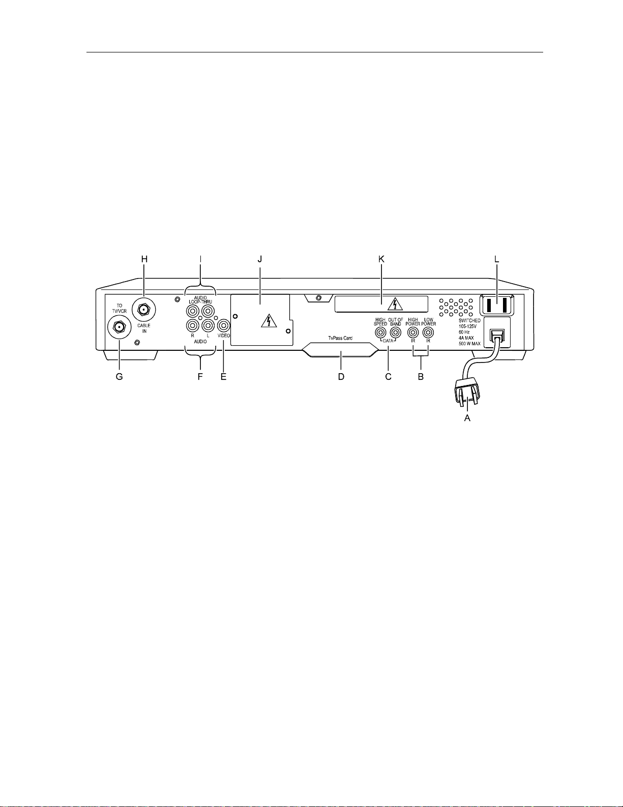
Figure 2-2
DCT 1000 cable terminal rear panel
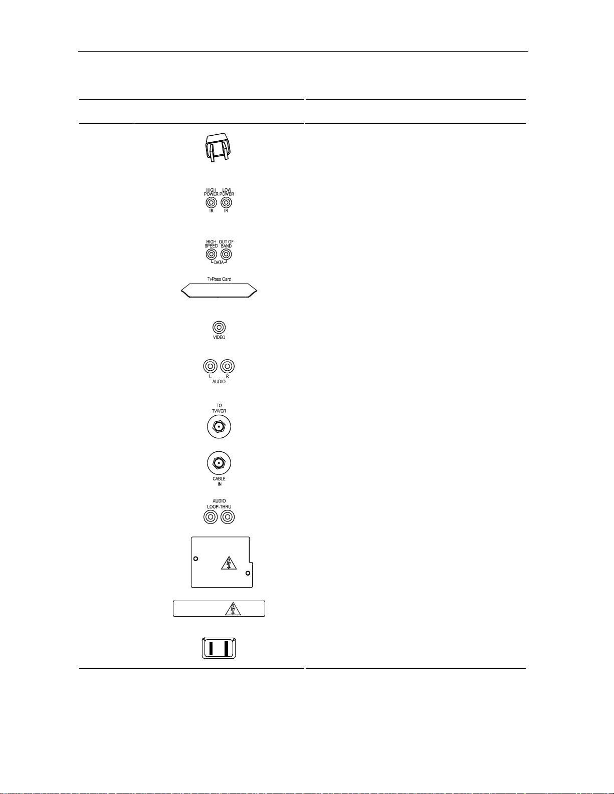
See the following table for the description of each of the rear panel features identified above.
DCT1000 Installation Manual
Page 13
2-4 Overview
Key Connector Function
A
B
C
D
E
F
G
Standard 2-prong polarized plug to connect the
cable terminal to a power source.
Mini phone jacks for connecting an optional IR
Blaster. The high power output is optional.
Mini phone jacks for connecting data output from the
terminal.
This slot is reserved for future use.
The RCA jack used to connect the cable terminal to
a composite (baseband) video TV or a monitor. In
some configurations this jack connects to a VCR.
The left and right audio RCA jacks used for stereo
audio output.
An F-type connector used to connect the cable
terminal to a standard TV or to a VCR.
H
I
J
K
L
An F-type connector used for the coaxial cable input
port.
The optional RCA jacks for looping through audio
from audio equipment.
Covers slot used for STARVUE II and STARFONE
options.
Covers slot reserved for future options.
An ac power outlet that can be configured as a
switched or unswitched outlet.
DCT1000 Installation Manual
Page 14

Overview 2-5
Configuration Options
The DCT 1000 platform supports a variety of configurations. These options allow your company
to offer options tailored to the needs of individual subscribers. Figure 2-3 shows the various
options available for the DCT 1000 platform.
Figure 2-3
DCT 1000 options
DCT1000 Installation Manual
Page 15

2-6 Overview
The following table describes the function of each of the options shown in Figure 2-3.
Optional Module Function
Used in a dual cable system to receive both cables. Please verify the location of
the A and B connectors on your particular A/B switch. They may be reversed.
Used to receive off-the-air signals from an antenna, or used to watch and/or
record channels at the same time.
Allows the cable signal to bypass the cable terminal and go directly to a TV or
VCR. An RF Bypass switch is internal on some DCT 1000 terminals. Before
installing an external switch, verify that the terminal does not have an internal
switch.
Used in a two-way addressable system to send impulse pay-per-view (IPPV)
information to the ACC 4000D or other controller through the return system.
Used in a two-way addressable system to send impulse pay-per-view (IPPV)
information to the ACC 4000D or other controller through the subscriber’s
telephone hookup.
Remote Controls
The basic DCT 1000 uses the XRC 100 remote control. If your system offers an optional
electronic program guide, a different remote control may be required; refer to Section 5, TV
Guide On Screen. The XRC 100 may require programming before use; refer to its user guide for
programming instructions.
DCT1000 Installation Manual
Page 16

XRC 100 Remote Control
Figure 2-4 illustrates the XRC 100.
Figure 2-4
XRC 100 remote control
Overview 2-7
Installing Batteries in Remote Control
Before a remote control can be used, two AA (1.5 volt) alkaline batteries must be installed in it.
Battery access is located on the back of the remote control.
To install batteries in an XRC 100:
Press and slide the battery compartment cover off.
1 Place the batteries in the compartment being careful to observe the correct polarity.
2 Slide the battery compartment cover back into place.
DCT1000 Installation Manual
Page 17

Section 3
Installation
This section provides step-by-step instructions for installing and cabling the cable terminal in
the subscriber’s location. The cabling diagrams shown in this section include the following
configurations, both with and without PPV options (STARFONE and STARVUE II):
n
Standard wiring
n
A/B Switch-out
n
A/B Switch-in
If you are adding a VCR or stereo components to the configuration, see Section 4, Adding a
VCR or Stereo Components, for cabling suggestions.
Before You Begin
Before beginning the installation process, do the following:
n
Look at the TV set or monitor to determine if it is a standard TV or a composite (baseband)
monitor. Make certain you have the correct connecting cables.
n
Make certain you have the correct connecting cables for the audio connectors.
n
Determine if you are going to connect a VCR to the DCT 1000 cable terminal.
n
If the subscriber location requires an A/B switch-in, an A/B switch-out, or a STARVUE II or
STARFONE module, install these options before beginning cabling. Installation of these
units is described in the installation instructions provided with them.
After installation is completed, the cable terminal should be placed on a smooth, flat surface
with no obstructions to interfere with the free flow of air over, under, and around the cable
terminal. Tell the subscriber that nothing should be placed on top of the unit.
Installing the DCT 1000
To install the DCT 1000 in your subscriber’s site:
Refer to the section that describes the cabling for the subscriber’s cable terminal configuration:
standard wiring (page 3-2), A/B switch-out (page 3-4); or A/B switch-in (page 3-6).
1 Follow the general instructions as you do the cabling.
2 Perform the basic operational check beginning on page 3-8 after you successfully install
the cable terminal.
3 Check the troubleshooting suggestions on page 3-9 if you have a problem with the
operational check.
DCT1000 Installation Manual
Page 18

3-2 Installation
General Configuration Instructions
The DCT 1000 cable terminal is available in numerous configurations. The cabling for each
configuration is illustrated in this section. Use these general installation instructions and the
cabling illustrations to install the terminal in the subscriber location.
To install the DCT 1000 cable terminal:
Connect the 75-Ohm coaxial cable drop to the F-type connector that is labeled
RF IN on the
cable terminal.
1 If your configuration includes a STARVUE II module, connect the 75-Ohm coaxial cable
jumper as shown on the appropriate configuration illustration.
2 To connect the video, do one of the following:
For a conventional TV set, use a 75-Ohm coaxial cable with F-type connectors to connect
the cable terminal labeled
TO TV either directly to the input of the TV set or through a
matching transformer to the 300-Ohm input of the set.
For a monitor, use a cable with an RCA connector to connect the cable terminal labeled
VIDEO to the monitor.
3 Plug the TV set into the convenience outlet on the back of the cable terminal.
Standard Wiring Cabling Diagrams
Figure 3-1 illustrates a standard wiring configuration. If the cable terminal has an RF or
telephone return modem, use Figure 3-2 or Figure 3-3) to determine the correct wiring for the
configuration.
Figure 3-1
Standard wiring without a PPV module
DCT1000 Installation Manual
Page 19
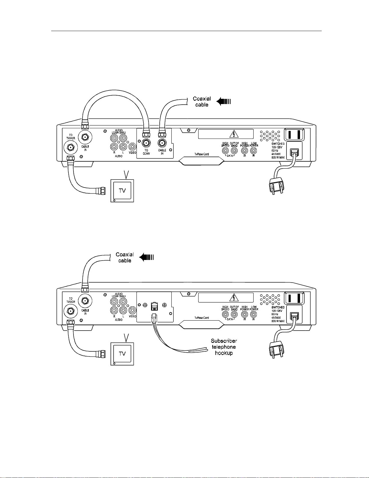
Figure 3-2
Standard wiring with a STARVUE II module
Installation 3-3
Figure 3-3
Standard wiring with a STARFONE module
DCT1000 Installation Manual
Page 20

3-4 Installation
A/B Switch-out Cabling Diagrams
Figure 3-4 illustrates a standard wiring configuration which includes an A/B switch-out. If
the cable terminal has a PPV module, refer to the PPV diagrams (Figure 3-5 and Figure 3-6)
to determine the correct cabling for the configuration.
Figure 3-4
A/B switch-out without a PPV module
DCT1000 Installation Manual
Page 21

Figure 3-5
A/B switch-out with a STARVUE II module
Installation 3-5
Figure 3-6
A/B switch-out with a STARFONE module
DCT1000 Installation Manual
Page 22

3-6 Installation
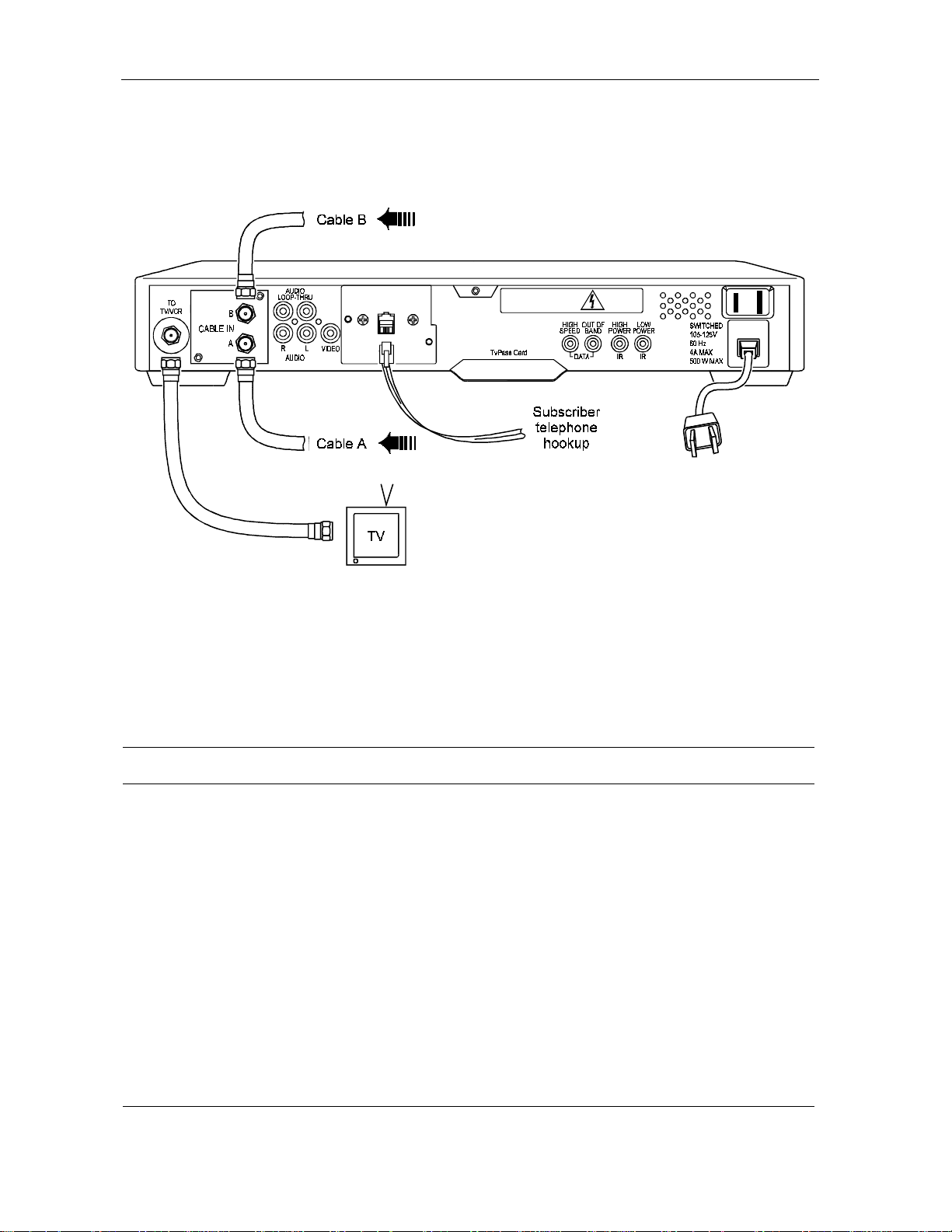
A/B Switch-in Cabling Diagrams
The A/B switch-in is commonly used in dual-cable systems. Figure 3-7 illustrates a standard
configuration that uses an A/B switch-in.
Figure 3-7
A/B switch-in without a PPV module
If the cable terminal is equipped with a PPV module, refer to the PPV diagrams (Figure 3-8,
Figure 3-9, and Figure 3-10) to determine the correct wiring for the configuration. The path
for the return system determines which configuration to choose, the one shown in Figure 3-8
(return on cable A) or the one shown in Figure 3-9 (return on cable B).
DCT1000 Installation Manual
Page 23

Figure 3-8
A/B switch-in with a STARVUE II module and the return on cable A
Installation 3-7
Figure 3-9
A/B switch-in with a STARVUE II module and the return on cable B
DCT1000 Installation Manual
Page 24
3-8 Installation
Figure 3-10
A/B switch-in with a STARFONE module
Operational Check
The operational check tests the communication link between the remote control and the cable
terminal. The procedures verify the terminal’s response to the remote control commands. You
use the remote control to test a basic cable terminal. If the terminal does not operate properly,
refer to the Troubleshooting section.
Testing Procedure Action
Power on 1 Press and release the POWER key to turn on the terminal.
2 Turn on the TV and tune it to the output channel of the cable terminal (channel
3 or 4).
Channel Selection
Volume Control
1 Scan through the channels using the CHANNEL keys on the cable terminal and
CHAN keys on the remote control.
the
2 Tune to several channels by entering the channel number with the numeric
keys on the remote control.
3 Using the TV set volume control, adjust the sound volume to a moderate level.
4 Using the VOL key on the remote control, increase the volume to its upper limit.
5 Again using the VOL key, reduce the volume to its lowest level. Adjust the
volume to a comfortable level using the
6 Press MUTE to turn the sound completely off. Press MUTE again to restore the
sound.
VOL key.
DCT1000 Installation Manual
Page 25

Installation 3-9
Troubleshooting
Occasionally a terminal may fail to operate as described. Follow these suggestions to correct
problems:
n
Press and release operation keys one at a time, firmly and deliberately.
n
Aim the remote control directly at the cable terminal, not the TV or VCR. Be sure there
are no obstructions between the remote control and the cable terminal.
n
Be certain that the TV set is tuned to the output channel of the terminal (channel 3 or 4).
If the channels can be changed with the cable terminal buttons, but not with the remote control
keys, the problem may be a weak remote control battery or the terminal is not initialized
correctly.
DCT1000 Installation Manual
Page 26
Section 4
Adding a VCR or Stereo Component
Depending on the options in the DCT 1000 and the equipment attached to the cable terminal,
there are numerous methods to connect a VCR or stereo equipment. This section gives a few of
the standard configurations.
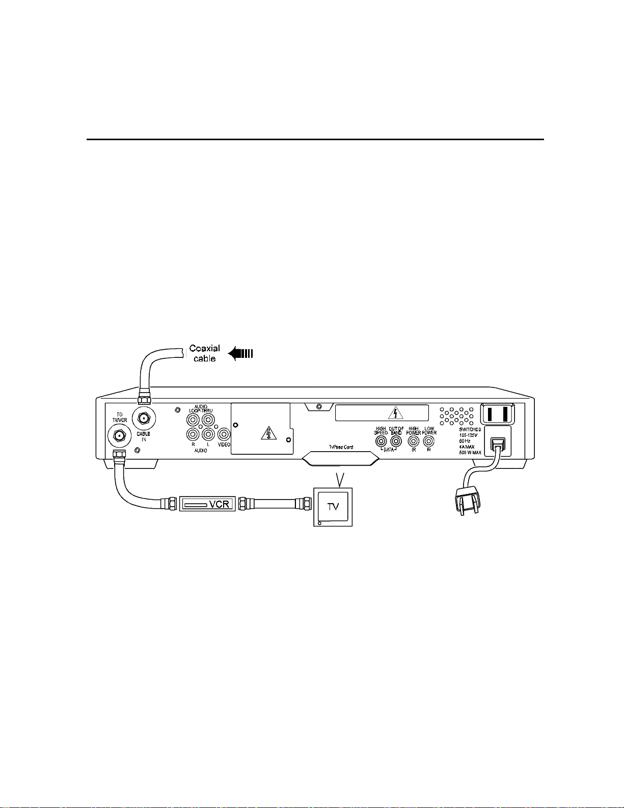
Standard VCR Cabling Diagram
The configuration shown in Figure 4-1 allows recording the same channel being viewed.
Figure 4-1
Standard VCR cabling
DCT1000 Installation Manual
Page 27

4-2 Adding a VCR or Stereo Component
RF Bypass Switch VCR Cabling Diagrams
The configurations shown in Figure 4-2 and Figure 4-3 allow viewing an unscrambled analog
channel directly on a TV while recording another channel through the terminal.
Figure 4-2
RF Bypass switch with VCR
DCT1000 Installation Manual
Page 28
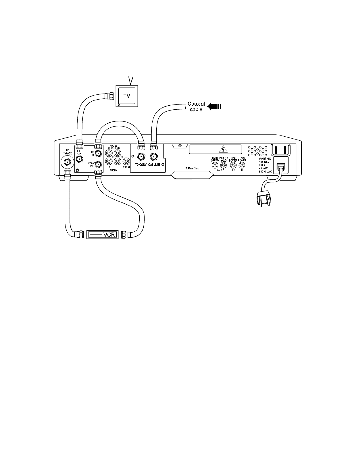
Figure 4-3
RF Bypass switch with VCR and STARVUE II module
Adding a VCR or Stereo Component 4-3
DCT1000 Installation Manual
Page 29

4-4 Adding a VCR or Stereo Component
A/B Switch-Out VCR Cabling Diagram
The arrangement shown in Figure 4-4 allows both the TV and the VCR to receive cable-ready
channels directly.
Figure 4-4
A/B switch-out with VCR
DCT1000 Installation Manual
Page 30

Adding a VCR or Stereo Component 4-5
A/B Switch-In VCR Cabling Diagram
The cabling configuration illustrated in Figure 4-5 allows for one of the following:
n
In the primary configuration (shown in solid lines), mode A tunes the TV to the VCR output
channel and the VCR can record a scrambled or non-scrambled channel. Mode B allows B
cable channels to operate in the same manner.
n
The alternate configuration (indicated by dotted lines), shows an optional placement for a
VCR in either the A or the B side.
Figure 4-5
A/B switch-in with VCR
DCT1000 Installation Manual
Page 31

4-6 Adding a VCR or Stereo Component
Composite (Baseband) VCR Cabling Diagram
The baseband audio and video outputs of the cable terminal are available to connect to a VCR
as displayed in Figure 4-6. The VCR can be cabled to either a standard TV by an F-type
connector or to a TV/monitor with audio and video connectors.
Figure 4-6
Composite VCR Cabling
DCT1000 Installation Manual
Page 32

Adding a VCR or Stereo Component 4-7
Stereo System Cabling Diagram
The configuration shown in Figure 4-7 uses the audio loop-through inputs on the DCT 1000. In
this configuration a subscriber’s CD player and VCR can be played through a stereo receiver.
Figure 4-7
Stereo system cabling
DCT1000 Installation Manual
Page 33

Section 5
TV Guide On Screen
The DCT 1000 supports the TV Guide On Screen electronic program guide. If your cable
company offers this service, this section will help you get TV Guide On Screen up and running
for your subscriber. It also describes a few basic operations to help you introduce the subscriber
to TV Guide On Screen. Refer the subscriber to the TV Guide On Screen Reference Guide for
complete instructions on all the features and their use.
Remote Control
When operating through the TV Guide On Screen program guide, the DCT 1000 uses the
XRC 200 remote control. The XRC 200 may require programming before use; refer to its user
guide for programming instructions.
DCT1000 Installation Manual
Page 34

5-2 TV Guide On Screen
XRC 200 Remote Control
Figure 5-1 illustrates the XRC 200 remote control.
Figure 5-1
XRC 200 remote control
Installing Batteries in Remote Control
Before a remote control can be used, two AA (1.5 volt) alkaline batteries must be installed in it.
Battery access is located on the back of the remote control.
To install batteries in an XRC 200 unit:
Press and slide the battery compartment cover off.
1 Place the batteries in the compartment, being careful to observe the correct polarity.
2 Slide the battery compartment cover back into place.
DCT1000 Installation Manual
Page 35

TV Guide On Screen 5-3
Quick Tips for the Program Guide
n
Use the directional arrows to navigate throughout the guide.
n
Yellow is the highlight color throughout the guide. Any item in the guide that is yellow is
currently highlighted.
n
To select a currently highlighted item, press OK.
n
To return to the previous screen, press LAST. Continue pressing LAST to return to television.
n
Typically, when pressing a key to enter a screen or mode, such as Menu, Browse, Fav, and
Help, pressing the same key will exit that screen or mode.
Setting Up the Program Guide
Once the DCT 1000 cable terminal has been successfully installed as described in Sections 3,
Installation, and Section 4, Adding a VCR or Stereo Components, it will take approximately 5 to
15 minutes for TV Guide On Screen to become functional with listings information for the
current hour. Inform the subscriber that it will take approximately 60 minutes to receive the
listing information for the next 36 hours. Please note that actual download times will be
determined following system testing.
To check the status of TV Guide On Screen, press
MENU on the remote control. If TV Guide On
Screen is not yet available, you will see the screen shown in Figure 5-2:
Figure 5-2
Notice screen
DCT1000 Installation Manual
Page 36

5-4 TV Guide On Screen
Confirm Proper Installation
Once TV Guide On Screen becomes available, follow these easy steps to confirm that it is
functioning properly:
Press
MENU
.
1 Press the Down Arrow to open the Viewer Services section of the menu.
2 Press the Right Arrow to highlight Setup.
3 Press OK. The setup screen shown in Figure 5 will appear:
Figure 5-3
Setup screen, with Cable Terminal selected
4 Highlight Cable Terminal, then press OK. The screen shown in Figure 5-4 will appear:
Figure 5-4
Cable terminal setup screen
DCT1000 Installation Manual
Page 37

TV Guide On Screen 5-5
5 Highlight Review, then press OK. The configuration screen shown in Figure 5-5 will appear.
Review the meaning of the various parts of the screen with the subscriber.
Figure 5-5
Configuration screen
6 After confirming that TV Guide On Screen is functioning properly, press MENU twice to
return to television viewing.
Configure TV Guide On Screen
Once you have confirmed that TV Guide On Screen is functioning properly, go through the
following steps with the subscriber. This will demonstrate to the subscriber how to configure the
guide to suit his or her needs:
MENU.
Press
1 Press the Down Arrow to open the Viewer Services section of the menu.
2 Press the Right Arrow to highlight Setup.
DCT1000 Installation Manual
Page 38

5-6 TV Guide On Screen
3 Press OK. The setup screen shown in Figure 5-6 will appear.
Figure 5-6
Setup screen, with TV Guide On Screen selected
4 Highlight TV Guide On Screen, then press OK. The screen shown in Figure 5-7 will appear.
Review the meaning of the various parts of the screen with the subscriber.
Figure 5-7
TV Guide On Screen Setup
5 Press MENU twice to return to television viewing.
DCT1000 Installation Manual
Page 39

TV Guide On Screen 5-7
Getting Started with the Program Guide
Here are a few things to point out to the subscriber about using TV Guide On Screen. Remind
the subscriber to refer to the TV Guide On Screen Reference Guide.
Flip
The flip bar will appear each time the channel is changed and will disappear after 5 seconds. To
make the flip bar appear or disappear on command, press
Browse
Press BROWSE and then the UP/DOWN arrows to see what’s on other channels without leaving
what you’re watching. Press
OK to tune to a channel seen by browsing. Press the RIGHT/LEFT
arrows to see what’s on at other times. The subscriber can choose to watch something that
comes on later by pressing
OK to set a reminder for it. Press BROWSE again to exit browse mode.
Listing Menus
OK.
Press MENU to view the Main Menu. Within the TV Guide On Screen section, you will see six
different ways that program listings are organized:
by Time, Channel, Title, Movies, Sports and
Children. To access a listing menu, highlight it then press OK.
Within each menu, you may do the following:
n
Highlight a program that is on now, press OK and tune to it.
n
Highlight a program that is on later, press OK and set a reminder for it.
n
Highlight a pay-per-view program, press OK and purchase it.
n
Highlight a program, press LOCK and lock it (locking restricts viewing).
Pay-Per-View
The subscriber can order a pay-per-view program, by following these steps:
Highlight the program title from within the pay-per-view menu or from any of the listing menus,
then press
browsing to the channel.)
1 Highlight the desired start time, then press OK.
2 Highlight Confirm (or enter your four-digit purchase code if you have one set), then press OK.
3 Reminders are automatically set for pay-per-view programs.
OK. (The subscriber can also purchase a pay-per-view program by flipping or
Messages
A yellow envelope in the upper right-hand corner of your screen indicates that you have a
message. To read the message:
Highlight Messages from within the Viewer Services section of the Main Menu, then press
1 Highlight the message, then press OK.
DCT1000 Installation Manual
OK.
Page 40

5-8 TV Guide On Screen
2 After reading the message, the subscriber can highlight either Keep or Delete, then press OK.
Lockout
The subscriber may restrict viewing of certain programs based on its MPAA rating, the channel
it’s on, or even its title. To set a lock:
Highlight Lockout from within the Viewer Services section of the Main Menu, then press
The subscriber may also press
LOCK while watching a program or while highlighting a program
OK.
name in any of the listing menus.
1 The subscriber would then enter his four-digit lockout code, then press OK.
2 To set a lock, highlight the desired rating, channel, or title, then press OK.
3 To remove a lock, highlight the locked criteria, then press OK.
Channel Manager
The Channel Manager can be used to locate and tune to a channel or to set favorite channels.
Highlight Channel Manager from within the Viewer Services section of the Main Menu, then
press
OK.
1 Highlight By Number to organize the list of channels numerically, or By Name to organize
them alphabetically.
2 Highlight a channel then press OK to tune to it.
3 Highlight a channel then press FAV to include/exclude it in the favorite channel list.
Timers
Setting a Timer forces the cable terminal to tune to a particular channel at a particular time.
This is a helpful tool for recording programs while the subscriber is not at home. To set a timer:
Highlight Timers from within the Viewer Services section of the Main Menu, then press
1 Highlight one of the eight Available bars, then press OK.
2 Enter the desired Timer information.
3 When all information is entered and the name of the desired program appears at the bottom
of the screen, press
OK to accept the Timer.
OK.
Help
Pressing the HELP key on the remote brings up helpful information pertaining to the portion of
the guide currently in use. To exit Help, press the
DCT1000 Installation Manual
HELP key again.
Page 41

Appendix A
Specifications
Input Frequency 54 to 860 MHz (excluding data carrier frequency)
HRC/IRC Frequency Assignments Downloadable
Number of Channels 136 carriers per cable, 1 or 2 cables
Analog 1 channel per carrier
Digital More than 1 channel per carrier, content dependent
Dual A/B Cable Switching Optional A/B switch (field upgradeable)
Input Analog Video Level 0 dBmV to +15 dBmV
Input Analog Sound Level –17 dBmV to +2 dBmV
Average Digital Input Level –10 dBmV to +5 dBmV
Data Carrier QPSK modulated carrier
Frequency 75.250 MHz
Bandwidth ± 200 kHz standard FM
Level –15 dBmV
Video S/N 49 dB @ 0 dBmV input level
Output Frequency Accuracy ± 150 kHz
Return Loss
Input 6 dB minimum
Output 8 dB minimum
Spurious Output –57 dBc maximum, in band
Cross Modulation Distortion –56 dB (136 channels, each @ + 15 dBmV)
Composite Second Order Distortion –57 dB (136 channels, each @ + 15 dBmV)
Second Order Distortion –60 dB (136 channels, each @ + 15 dBmV)
Composite Triple Beat Distortion –57 dB (136 channels, each @ + 15 dBmV)
Converter Input Beats (With All Input
Signals)
Hum Modulation Distortion 3 IRE
Output Level 10 to 15 dBmV
–25 dB (136 channels, each @ + 15 dBmV)
Isolation (Input/Output) 70 dB minimum
DCT1000 Installation Manual
Page 42

A-2 Specifications
Differential Phase 10 degrees (maximum)
Scrambling Method Gated sync suppression or dynamic gated sync suppression,
video inversion, audio privacy, Hamlin compatibility
On Screen Display
Screen Size 352 x 480 pixels
Message/Barker Capacity Up to 40 pages (configuration dependent)
Channel Descriptors 4 character, maximum
Mechanical Security Standard: security screws; security pin; uni-chassis
construction
Two-Way Systems Compatibility With addition of STARVUE II, STARFONE, or Network
Module
Operating Environment Range
Temperature 0 to 40 degrees C (32 to 104 degrees F)
Humidity 5 to 95% (non-condensing)
ac Voltage 105 Vac to 125 Vac, 60 Hz
Power Dissipation 45 watts at 115 VAC
Surge Protection Provided on power supply and RF ports
Size 17.13 × 13.25 × 2.75 inches
Weight 10 pounds
DCT1000 Installation Manual
Page 43

Appendix B
Diagnostics
This section describes the diagnostics provided for the DCT 1000 cable terminal. The
diagnostics are designed to confirm proper installation of the DCT 1000. They include
provisions to identify the terminal on the network and to verify communications with the
headend. The diagnostic information is displayed on the terminal’s front panel LEDs and on
the on screen display (OSD).
Accessing Diagnostics
To put the DCT 1000 in the diagnostic mode:
1 Install the DCT 1000.
2 Connect the cable terminal to an ac outlet.
3 Press POWER to turn the cable terminal on.
4 Wait five seconds.
5 Press POWER to turn the terminal off.
6 Within two seconds, press SELECT. The cable terminal is now in the diagnostic state, as
indicated by the appearance of the diagnostics screen (Figure B-1) and the display of d 01
on the front panel LEDs.
7 Use the CHANNEL keys to select the desired diagnostic.
8 Press the CURSOR < or CURSOR > key to execute the selected diagnostic.
9 To exit the diagnostic mode, press POWER.
DCT1000 Installation Manual
Page 44

B-2 Diagnostics
Figure B-1
Diagnostics selection OSD display data
DCT 1000 DIAGNOSTIC SELECTION
01 GENERAL STATUS
02 OOB STATUS
03 IN-BAND STATUS
04 IN-BAND STATUS SHORT-TERM ERROR
RATE
05 IN-BAND STATUS LONG-TERM ERROR RATE
06 UNIT ADDRESS
07 SERIAL NUMBER
08 DENA FIRMWARE VERSION
09 DECRYPTOR STATUS
10 RENEWABLE SECURITY SYSTEM
11 UPSTREAM MODEM STATUS
12 APPLICATION CODE MODULES
13 APPLICATION EXP. MODULE
14 MEMORY CONFIGURATION
Summary of Diagnostic Modes
The following table summarizes the diagnostic modes:
LED Diagnostic LED OSD
d 01 General status of the DCT 1000 X X
d 02 QSPK out-of-band receiver status X X
d 03 64 QAM in-band receiver status/analog channel status X X
d 04 64 QAM short-term error count X X
d 05 64 QAM long-term error count X X
d 06 Unit address X X
d 07 Unit serial number X X
d 08 Dena firmware version X X
d 09 Current channel status X X
d 10 Renewable security system X X
d 11 Upstream modem status X X
d 12 Application code modules X
DCT1000 Installation Manual
Page 45
Diagnostics B-3
LED Diagnostic LED OSD
d 13 Application expansion module X
d 14 Memory configuration X
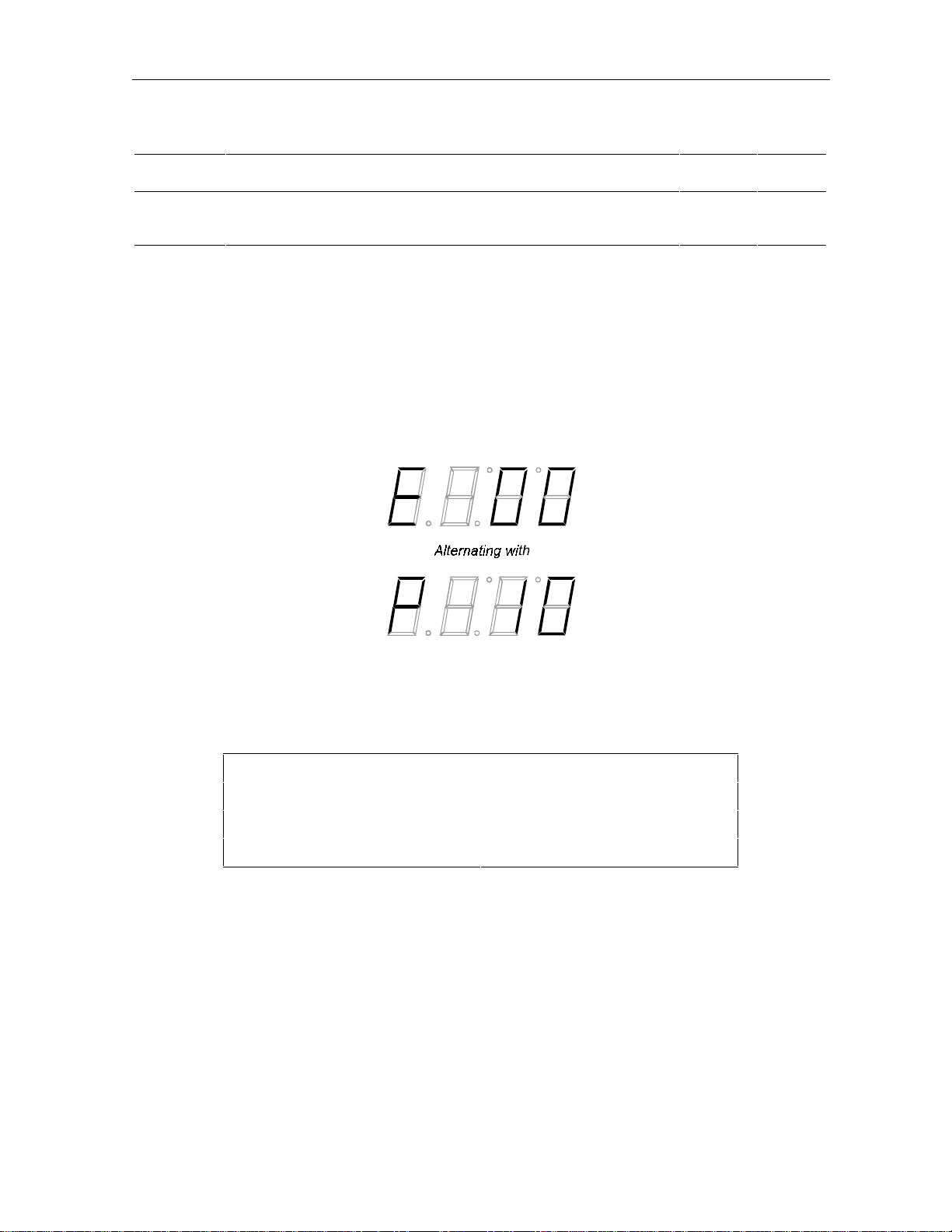
d 01: DCT 1000 General Status
This diagnostic indicates the general status of the terminal. The LED display (Figure B-2)
alternates between the error code and the purchase count. The OSD display (Figure B-3))
shows the error code, a short description of the error, and the purchase count.
Figure B-2
General status LED display
Figure B-3
General status OSD display data
ERROR: E00
NO ERROR
PURCHASES 10
DCT 1000 STATUS
DCT1000 Installation Manual
Page 46

B-4 Diagnostics
Remedy
Not applicable.
Not applicable.
Return unit to repair
center.
Not applicable.
Initialize terminal to clear
the error. If error persists,
return unit for repair.
Return the terminal for
repair.
Return the terminal for
repair.
Return the terminal for
repair.
Not applicable.
Currently, the following error codes are supported:
Error Code On Screen Display Cause
E 00 NO ERROR Indicates normal condition
after initialization.
E 01 to E 06 Not currently defined.
E 07 FAULTY ROM Faulty ROM.
E 08 Not currently defined.
E 09 FAULTY RAM Faulty RAM or dead battery.
Occurs if the battery fails to
keep the RAM alive during
power down. This causes
the terminal to be
disconnected.
E 10 INVALID SERIAL NUMBER Invalid serial number.
E 11 INVALID UNIT ADDRESS Invalid unit address.
E 12 POST Terminal fails power on self
test.
E 13 to E99 Not currently defined.
d 02: Out-Of-Band Receiver Status
This diagnostic indicates the status of the out-of-band receiver. The LED and OSD displays are
shown in Figure B-4 and Figure B-5. The condition of no data received is indicated by the LED
display shown in Figure B-6.
Figure B-4
Out-of band status LED display
DCT1000 Installation Manual
Page 47

Figure B-5
Out-of-band status OSD display data
OUT-OF-BAND DIAGNOSTIC
DATA *
EMM DATA *
CARRIER LOCK YES
PACKET/FRAME SYNC YES
Figure B-6
LED indication of no data received
Diagnostics B-5
Carrier Lock
Carrier lock indicates whether or not the out-of-band receiver is locked to the carrier. LED and
OSD indications are as follows:
LED OSD Status
C YES Carrier locked
u NO Carrier unlocked
Packet/Frame Sync
Packet/frame sync indicates whether the out-of-band receiver is synched to the incoming data
stream. The carrier must be locked before packet boundaries can be detected.
LED OSD Status
P YES Packet/frame synched
u NO Packet/frame unsynched
DCT1000 Installation Manual
Page 48

B-6 Diagnostics
Data Activity
Indicates that a message was received. The indicator will be cleared when this diagnostic mode
is entered and three seconds after the last message is received. The indicator covers all packet
processors regardless of which stream they are monitoring.
LED OSD Status
off blank No data received
on * Data received
EMM Data Activity
Indicates that a message was received on the EMM stream. The indicator will be cleared when
this diagnostic mode is entered, and three seconds after the last message is received.
LED OSD Status
off blank No data received
on * Data received
d 03: In-Band Receiver Status
The DCT 1000 displays the digital diagnostics. If there is no digital carrier, these diagnostics
indicate the carrier is not locked. The LED and OSD displays are shown in Figure B-7 and
Figure B-8.
Figure B-7
In-band receiver digital status LED display
DCT1000 Installation Manual
Page 49

Diagnostics B-7
Figure B-8
In-band receiver digital status OSD display data
IN-BAND DIAGNOSTIC: DIGITAL
DATA *
EMM DATA *
CARRIER LOCK YES
REED/SOLOMON YES
PACKET/FRAME SYNC YES
Carrier Lock
This diagnostic indicates whether or not the in-band receiver is locked to the carrier. The LED
and OSD indications are as follows:
LED OSD Status
C YES Carrier locked
u NO Carrier unlocked
Reed-Solomon Sync
The Reed-Solomon FEC packet sync indicates if the Forward Error Correction hardware is
synched up on FEC boundaries. The carrier must be locked before packet boundaries can be
detected.
LED OSD Status
O YES Reed-Solomon FEC packet sync OK
u NO Reed-Solomon FEC packet unsynched
Packet/Frame Sync
Packet/frame sync indicates the status of the in-band receiver front end.
LED OSD Status
P YES Packet/frame synched
u NO Packet/frame unsynched
DCT1000 Installation Manual
Page 50

B-8 Diagnostics
Adaptive Equalizer Stress
The status of the adaptive equalizer (AE) is indicated as follows:
LED OSD Status
on YES AE is near its operating limit
off NO AE is operating within design parameters
Data Activity
Indicates that a message was received. The indicator will be cleared when this diagnostic mode
is entered and three seconds after the last message is received. The indicator covers all packet
processors regardless of which stream they are monitoring.
LED OSD Status
off blank No data received
on * Data received
EMM Data Activity
Indicates that a message was received on the EMM stream. The indicator is cleared when this
diagnostic mode is entered and three seconds after the last message is received.
LED OSD Status
off blank No data received
on * Data received
d 04: QAM Receiver Short-Term Error Rate
This diagnostic displays the latest Reed-Solomon error count (a 16-bit counter) approximately
every five seconds. This value is displayed as four hex digits on the LED display, and is
updated approximately every five seconds. The OSD screen also displays the adaptive
equalizer coefficients 0 to 39.
The LED and OSD displays are shown in Figure B-9 and Figure B-10.
Figure B-9
Receiver short-term error rate LED display
DCT1000 Installation Manual
Page 51

Figure B-10
Receiver short-term error rate OSD display data
IN-BAND RECEIVER STATUS
SHORT-TERM ERROR COUNT
10
AE COEFFICIENTS (1 of 2)
01234
00 000 001 002 003 004
05 005 006 007 008 009
10 010 011 012 013 014
15 015 016 017 018 019
20 020 021 022 023 024
25 025 026 027 028 029
Diagnostics B-9
30 030 031 032 033 034
35 035 036 037 038 039
d 05: QAM Receiver Long-Term Error Rate
This diagnostic displays the latest Reed-Solomon error rate over an extended period of time,
typically 24 hours. This value is displayed as four hex digits on the LED display. The OSD
screen also displays the adaptive equalizer coefficients 40 to 79.
The LED and OSD displays are shown in Figure B-11 and Figure B-12.
Figure B-11
Receiver long-term error rate LED display
DCT1000 Installation Manual
Page 52

B-10 Diagnostics
Figure B-12
Receiver long-term error rate OSD display data
IN-BAND RECEIVER STATUS
LONG-TERM ERROR COUNT
200
AE COEFFICIENTS (2 of 2)
01234
40 040 041 042 043 044
45 045 046 047 048 049
50 050 051 052 053 054
55 055 056 057 058 059
60 060 061 062 063 064
65 065 066 067 068 069
70 070 071 072 073 074
75 075 076 077 078 079
d 06: Unit Address
This diagnostic displays the terminal’s 16-digit (40-bit) unit address, which is written at
manufacturing time. It shows in five parts on the four-section LED display. The address
display stays on each section for five seconds. An example of the LED display for unit address
123-45678-90123-456 is shown in Figure B-13.
On the OSD screen, illustrated in Figure B-14, the unit address is shown in the decimal form
and in the TCP/IP decimal byte form. All the other addresses are shown in TCP/IP decimal
byte form.
DCT1000 Installation Manual
Page 53

Figure B-13
Unit address LED display
Diagnostics B-11
Figure B-14
Unit address OSD display data
Unit Address
Unit Address 123-45678-90123-456
Network Address 123-45678-90123-456
TVPC 123-45678-90123-456
Multicast 16 Address 255.255 255.255
255.255 255.255
d 07: Unit Serial Number
This diagnostic displays the terminal’s unit serial number which is assigned at manufacture. It
is shown in parts on the four LED sections. The serial number display will stay lit on each part
for five seconds. The meaning of the digits in each four-digit group is as follows:
n
First digit: The position, in hex notation.
n
Second digit: The ASCII character.
n
Third and fourth digits: The hex value of the ASCII character.
DCT1000 Installation Manual
Page 54

B-12 Diagnostics
A typical LED display for the first part of a serial number is shown in Figure B-15.
Figure B-15
Unit serial number LED display
The serial number is displayed directly on the OSD screen, as illustrated in Figure B-16.
Figure B-16
Unit serial number OSD display data
DCT 1000 SERIAL NUMBER
D53G9176543267
d 08: Dena Firmware Version
This diagnostic shows the Dena firmware version. The LED display, as illustrated in Figure
B-17, alternates between showing the firmware version number and the characters dENA.
Figure B-17
Dena firmware version LED display
DCT1000 Installation Manual
Page 55
Diagnostics B-13
The OSD screen, as illustrated in Figure B-18, displays the revision number and the build date.
Figure B-18
Dena firmware version OSD display data
DENA FIRMWARE VERSION
12.34
12/31/94
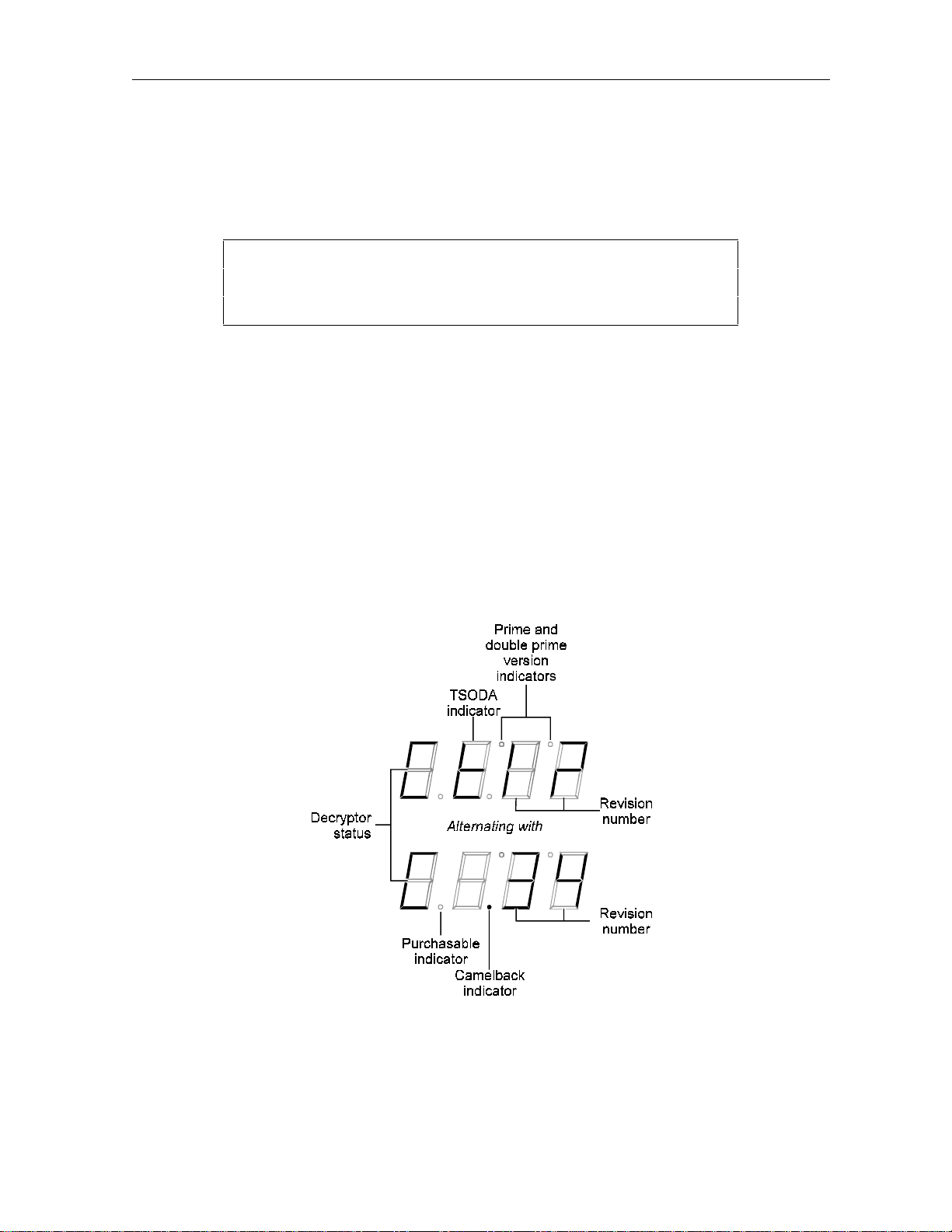
d 09: Current-Channel Status
This diagnostic gives the instantaneous status of the last tuned channel on the in-band tuner.
It indicates if the current program is analog clear, analog with tagging data, barker channel, or
a digital channel. This diagnostics also indicates if the current channel is purchasable.
The LED display, illustrated in Figure B-19, alternates between the TSODA firmware version,
and the camelback firmware version. The decryptor status is indicated for the currently tuned
channel and type. This is in spite of showing both TSODA (digital) and camelback (analog)
firmware versions.
Figure B-19
Decryptor status LED display
DCT1000 Installation Manual
Page 56

B-14 Diagnostics
The OSD screen is shown in Figure B-20.
Figure B-20
Decryptor status OSD display data
CURRENT-CHANNEL STATUS
STATUS CLEAR
PURCHASABLE YES
TSODA VERSION 12
CAMEL VERSION 34
Decryptor Status Modes
The LED and OSD indications of the decryptor status modes are as follows:
LED OSD Meaning
C CLEAR Clear analog channel
S SCRAM Analog channel with tagging data
b BARK Barker channel
d DIGIT Decrypted digital program
Purchasable Status
The LED and OSD indications for purchasable status are as follows:
LED OSD Meaning
off NO Channel is not purchasable at present
on YES Channel is purchasable at present
DCT1000 Installation Manual
Page 57

Diagnostics B-15
d 10: Renewable Security System
The renewable security system returns the current status of the TvPC. This includes an
indication of whether or not the TvPC is required, and the mode, status and version.
The LED display is shown in Figure B-21.
Figure B-21
Renewable security status LED display
The OSD screen is shown in Figure B-22.
Figure B-22
Renewable security status OSD display data
RENEWABLE SECURITY SYSTEM STATUS
TVPC NOT REQUIRED
CRYPTO STAND ALONE
STATUS 00
VERSION 04
TvPC Required
The requirement for TvPC is indicated as follows:
LED OSD Status
n NOT REQUIRED TvPC not required
Y IS REQUIRED TvPC is required
DCT1000 Installation Manual
Page 58

B-16 Diagnostics
LED
00
01
02
03
04
05
0a
0b
0C
0d
Current Mode
The current mode is indicated as follows:
LED OSD Status
A STAND ALONE Stand alone
S SUPPORT Support
n NOT MATED Not mated
TvPC Status
TvPC status is indicated as follows:
OSD Status
00 OK
01 TvPC communication problem
02 TvPC required
03 Validator does not match between GK and TvPC
04 Invalid unit key number
05 Old TvPC unit address
0a TvPC not mated
0b TvPC/base module unit address mismatch
0C New TvPC, but wrong version number
0d TvPC unit address mismatch
d 11: Upstream Modem Status
These diagnostics will display the appropriate set of RF or telephone modem information based
on the module installed within the cable terminal. Note that a false indication of the presence
of a STARFONE module is possible.
DCT1000 Installation Manual
Page 59
Diagnostics B-17
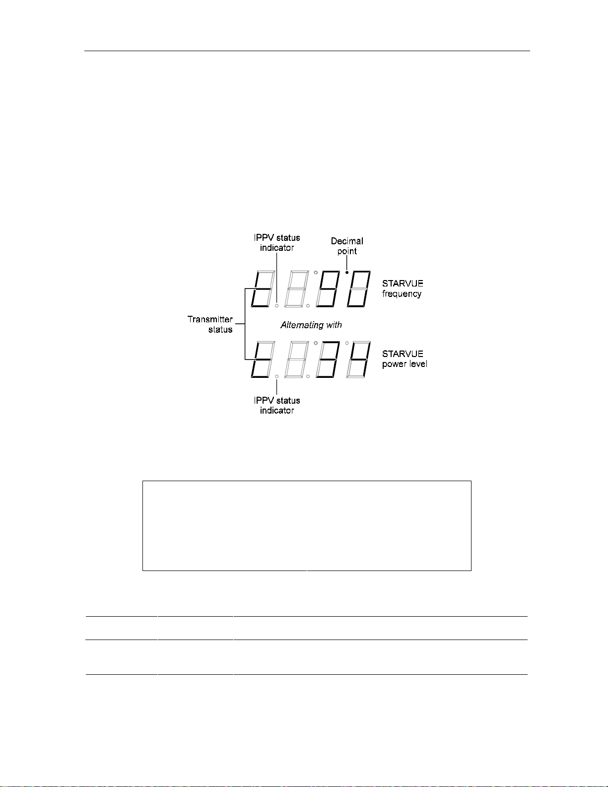
STARVUE II Diagnostics
This diagnostic shows the status and operating parameters for the STARVUE II module. The
LED and OSD displays are shown in Figure B-23 and Figure B-24.
Transmit frequency is shown in megahertz. The display range is 8.0 to 15.0 MHz
Level shows the hex value of the power level of the STARVUE II transmitter. This is a relative
value and is used for balancing the received power at the headend.
Figure B-23
STARVUE II diagnostics LED display
Figure B-24
STARVUE II diagnostics OSD display data
STARVUE II DIAGNOSTICS
STATUS t
FREQUENCY 9.0 MHz
LEVEL 34
IPPV DISABLED
Transmitter status is indicated as follows:
LED OSD Status
–– Idle
tt Transmitting
DCT1000 Installation Manual
Page 60

B-18 Diagnostics
IPPV status is indicated as shown in the following table. Note that UNSENT is followed by the
number of unsent transactions.
LED OSD Status
on ENABLED IPPV enabled
flashing UNSEEN– ## This terminal contains unsent IPPV transactions
off DISABLED IPPV disabled
STARFONE Diagnostics
This diagnostic shows the status and operating parameters for the STARFONE module. The
LED and OSD displays are shown in Figure B-25 and Figure B-26.
Figure B-25
STARFONE diagnostics LED display
Figure B-26
STARFONE diagnostics OSD display data
STARFONE DIAGNOSTICS
STATUS h–
CARRIER *
BAUD 300
PARAMETERS NOT SET
20 DIGIT PH#1 1-215-555-1234
20 DIGIT PH#2 1-215-555-5678
DCT1000 Installation Manual
Page 61

The status of the transmitter is shown as follows:
1st Digit 2nd Digit Meaning
Diagnostics B-19
h
t
d
A
c
c
c
r
* On Hook (* = hang-up code)
– Test for line available
– Dialing
– Waiting for answer
r Communicating, receiving
t Communicating, transmitting
– Communicating, Idle
* Waiting for retry (* = hang-up code)
The hang-up code is shown as follows:
Mode Status
– Normal hang-up
A Answer time-out
r Phone ringing
c Carrier loss
L Line in use
E Errors (data)
U User line request
P Parameters invalid
t Data time-out
C Communication protocol fault
The IPPV status indicator is shown as follows:
LED OSD Mode
on ENABLED IPPV enabled
flashing UNSENT This terminal contains unsent IPPV transactions
off DISABLED IPPV disabled
DCT1000 Installation Manual
Page 62

B-20 Diagnostics
The third digit baud rate is shown as follows:
LED OSD Mode
3 300 300 Baud
The fourth digit telephone parameters are shown as follows:
LED OSD Mode
— NOT SET Telephone parameters not set
P (flashing) NOT VALID Telephone parameters not valid
P (solid) SET Telephone parameters OK
d 12: Application Code Modules
This diagnostic displays the currently downloaded code modules. This can be a multipage
display. Additional pages are displayed by pressing the
SELECT key on the cable terminal.
The OSD display is shown in Figure B-27. There is no LED display for this diagnostic.
Figure B-27
Application code modules OSD display data
APPLICATION CODE MODULES
MODULE VERSION STATUS
d 13: Application Expansion Modules
This diagnostic indicates the presence of expansion modules in the terminal. The OSD display
is shown in Figure B-28. There is no LED display for this diagnostic.
Figure B-28
Application expansion modules OSD display data
APPLICATION EXPANSION MODULES
MODULE VERSION STATUS
DCT1000 Installation Manual
Page 63

Diagnostics B-21
d 14: Memory Status
The memory free value is the sum of all free memory. This free memory is not necessarily in
one block. The OSD display is shown in Figure B-29. There is no LED display for this
diagnostic.
Figure B-29
Memory status OSD display data
MEMORY STATUS
TYPE TOTAL FREE
NVRAM 129072 18954
DRAM 258435 10876
DCT1000 Installation Manual
Page 64

General Instrument Corporation
GI Communications Division
Printed in U.S.A.
405957-001-99, 7/96
 Loading...