

Page 1
1. CASSETTE TYPE :
AUA30LBLU
AUA36LBLU
INDOOR UNIT
D2D_AU034E/01
2008.05.08
R410A
Page 2
- (01 - 01) -
CASSETTE TYPE
AU
A30-36L
CASSETTE TYPE
AU
A30-36L
FEATURE1.
MODEL
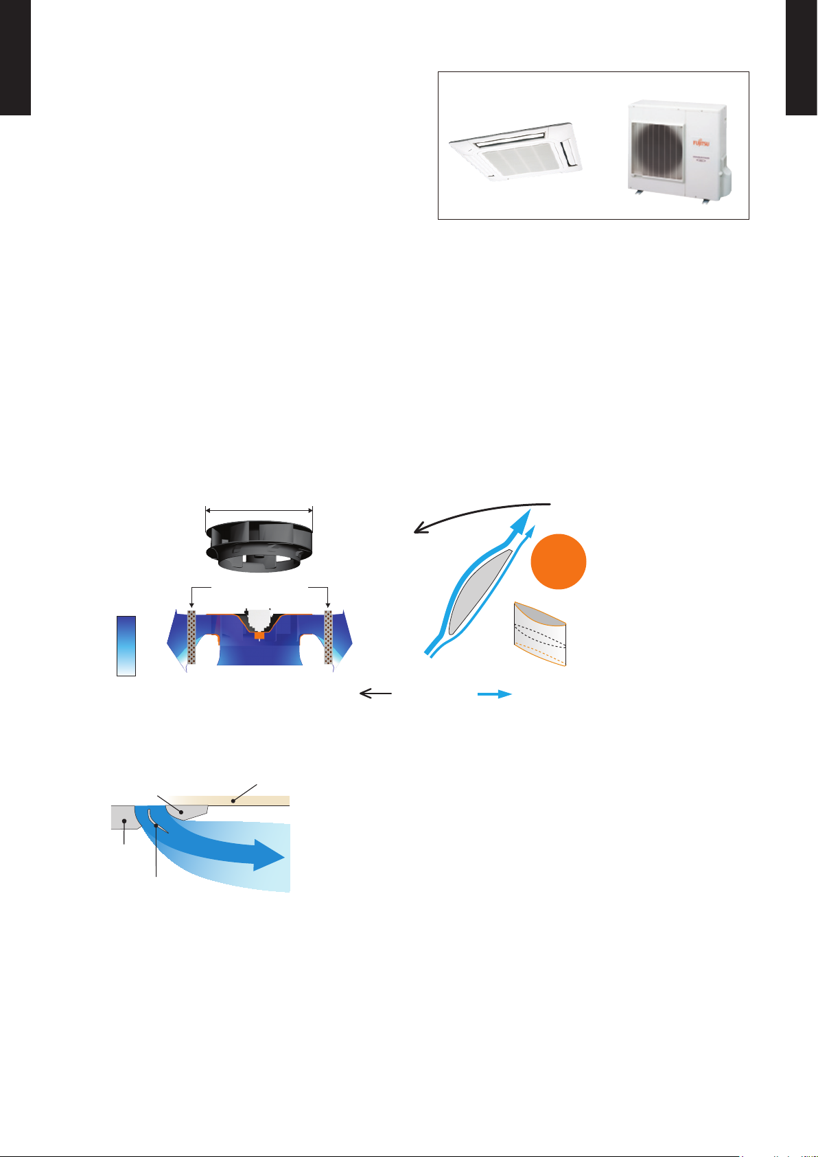
AUA30LBLU / AOA30LBTL
AUA36LBLU / AOA36LBTL
FEATURES
Energy saving
z
All dc design •
Heat exchange efciency increased and larger air ow by adoption of new type turbo fan •
Advancement in comfort
z
Quiet operation was realized by adoption of new type turbo fan •
Improvement of air stream •
Adoption of new type turbo fan
High efciency achieved by equaling the performance of the wing and air passing the heat
exchanger
Adoption of round flap
Making space between the ceiling, the air ows far wide and ceiling does not get dirty.
500mm
Wind
velocity
Fast
Slow
3-dimensional wing
: Spin direction : Airflow direction
No airflow
separation
Quiet
< Motor side >
Heat exchanger
Rear part
Front part
Ceiling
Round Flap
Page 3
- (01 - 02) -
CASSETTE TYPE
AU
A30-36L
CASSETTE TYPE
AU
A30-36L
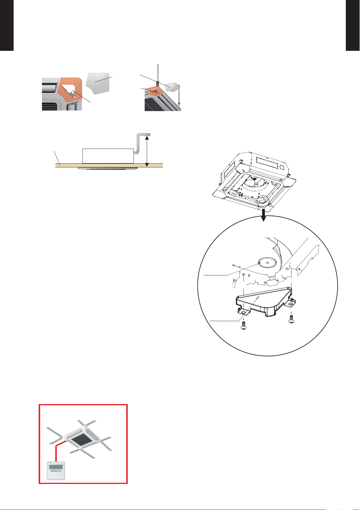
High lift drain pump
z
850mm
Ceiling panel
Simplication of drain water check
z
Drain and contamination check are possible
without removing the decoration panel.
Can be easily checked by removing the drain
cover.
DRAIN CAP
DRAIN COVER
Easy installation
z
Easy setting by wired
remote controller
Improvement of installation & maintenance
z
Adjustment of nut is possible after installation •
Mounting position of body can be ne adjusted after Decoration panel mounting.
Grille corner
Adjustment
can be done just taking
off the corner part
Page 4
- (01 - 03) -
CASSETTE TYPE
AU
A30-36L
CASSETTE TYPE
AU
A30-36L
FUNCTION SETTING
Other functions
z
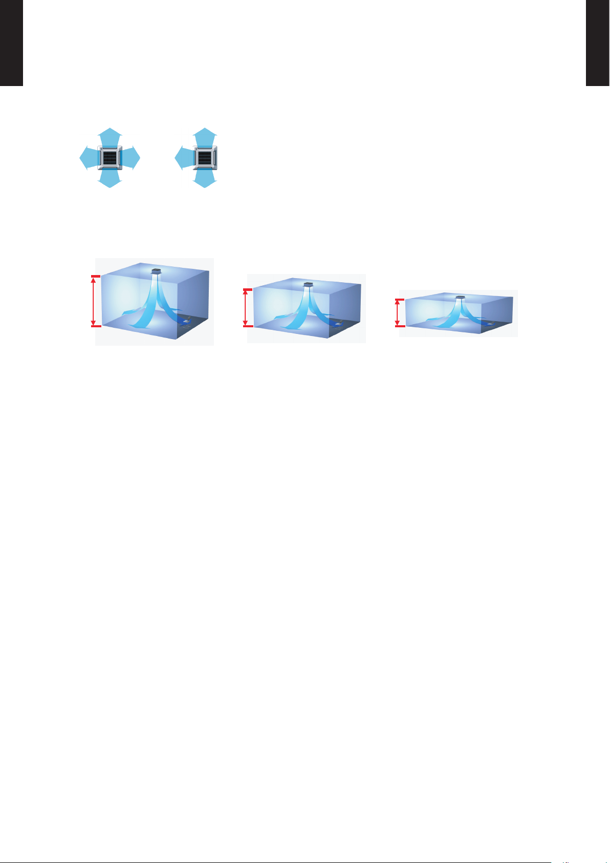
The number of air outlet can be selected. •
High and Low ceiling mode •
Air ow setting can be selected according to the height of the ceiling.
Setting the lter sign •
The indoor unit has sign to inform the user that it is time to clean the lter
Setting the cooler room temperature correction •
Setting the heater room temperature correction •
Auto restart •
4-way direction 3-way direction
Low ceiling
5m
3.2m
2.5m
High ceiling Standard ceiling
Page 5
- (01 - 04) -
CASSETTE TYPE
AU
A30-36L
CASSETTE TYPE
AU
A30-36L
REMOTE CONTROLLER2.
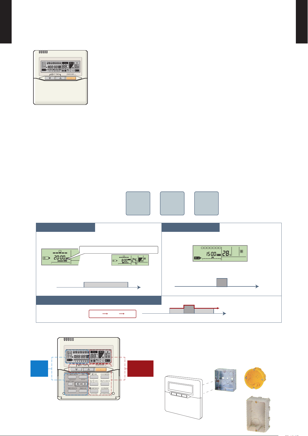
WIRED REMOTE CONTROLLER
FEATURES
Various timer setup (ON / OFF / WEEKLY) are possible.
¾
Equipped with weekly timer as standard function.
¾
(2 times Start / Stop per day for a week)
When setting up a timer, operation mode and a temperature
¾
setup can be changed.
When a failure occurs,the error code is displayed. (Maximum of 16)
¾
Error indication.(A maximum of 16 error histories are memorizable.)
¾
Up to 16 indoor units can be simultaneously controlled.
¾
Economy operation are possible.
¾
Easy installation with a slim shape with no bulge in the back.
¾
The room temperature can be controlled by being detected the
¾
temperature accurately with built-in thermo sensor.
Simple function setting
z
Setting of the air conditioner selection function is performed by remote controller.
High performance and compact size
z
Three functions are combined in
one unit.
Built-in timers
z
Wired
remote
controller
Weekly
timer
Setback
timer
+ +
Weekly timer Setback timer
At "Weekly timer" + "Set back timer" setup
Easy-to-understand operation
z
[Variable timer control]
The operation/display sections are zoned
according to time and operation, enabling
variable programming to match application.
Simple installation
z
Components are compatible with standard
switch boxes. Flat back construction allows
equipment to be installed wherever it is
needed.
SUMOTUWETH FR SA
7
3126 9
15 18 21
SUMOTUWETH FR SA
7
3126 9
15 18 21
SUMOTUWETH FR SA
3126 9
15 18 21
Possible to set ON/OFF time to operate twice each day
of the week.
Setup screen example
(Set to Wednesday: 8:00 to 20:00.)
Screen
after setup
European
switch box
JIS box
Setup screen example
(Set from Sunday to Saturday: 12:00 to 15:00, 28 °C.)
Possible to set temperature for two time spans and
for each day of the week.
Easy-to-understand time bar display
24°C
0 3 6 9 12 15 18 21 Time
28°C
0 3 6 9 12 15 18 21 Time
28°C
24°C
0 3 6 9 12 15 18 21 Time
24°C 28°C 24°C
Timer
area
Operation
area
Page 6
- (01 - 05) -
CASSETTE TYPE
AU
A30-36L
CASSETTE TYPE
AU
A30-36L
FUNCTIONS
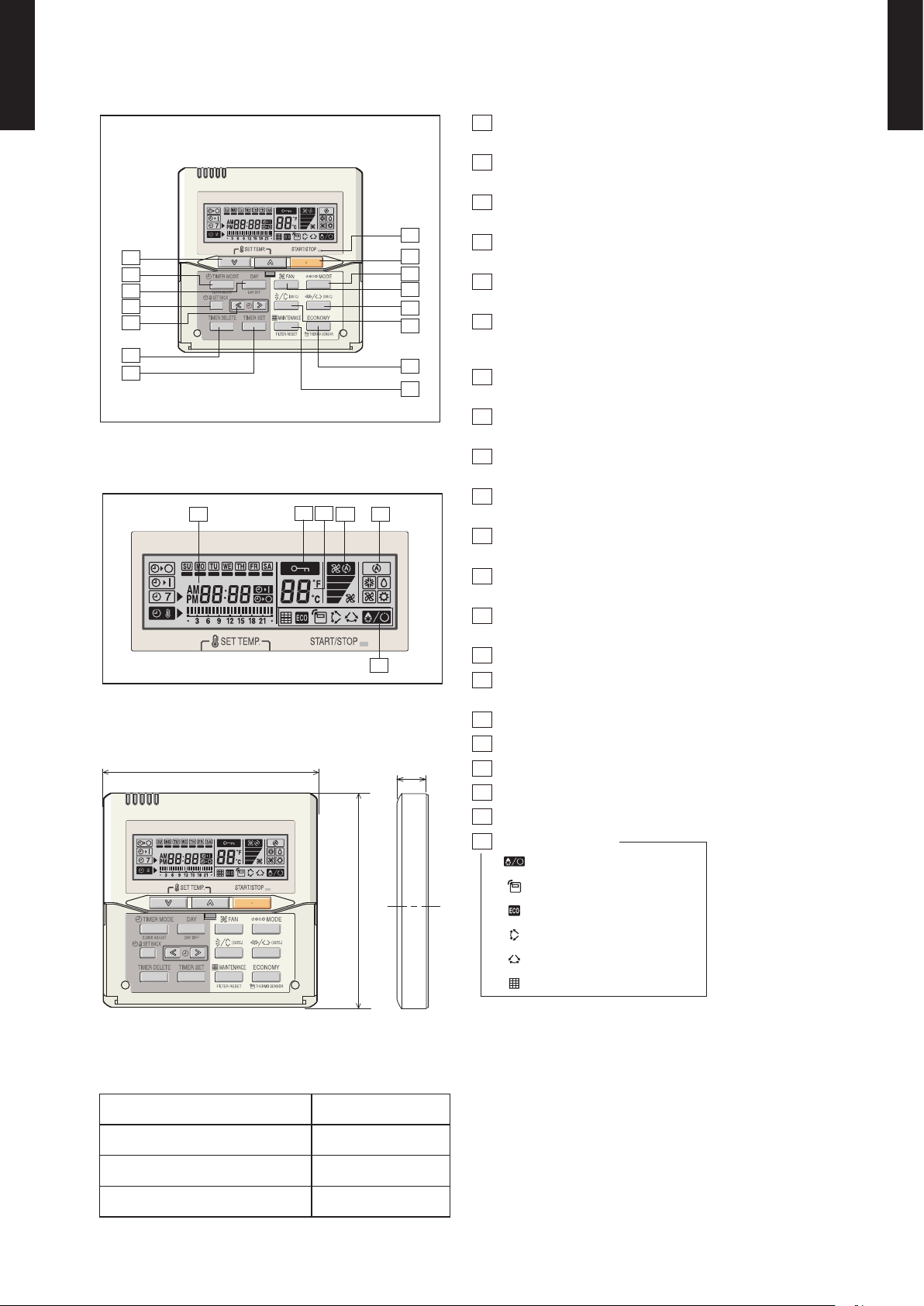
Display panel
DIMENSION
SPECIFICATION
15
11
10
9
8
2
1
3
5
14
4
12
13
6
7
17
16
18
19
20
21
120
17
120
SIZE (H x W x D mm) 120 x 120 x 17
WEIGHT ( g ) 160
CABLE LENGTH ( m ) 10
POWER ( V ) 12
1
START/STOP button
Pressed to start and stop operation.
2
Set temperature button
Selects the setting temperature.
3
Master control button
Selects the operating mode(AUTO, HEAT, FAN, COOL, DRY).
4
Fan control button
Selects the fan speed (AUTO, QUIET, LOW, MED, HIGH).
5
Economy button
Turns the economy efcient mode on and off.
6
Timer mode (CLOCK ADJUST) button
Selects the timer mode (OFF TIMER, ON TIMER, WEEKLY
TIMER). Set the current time.
7
Day (DAY OFF) button
Temporarily cancels of one day timer.
8
Set back button
Pressed to select the set back timer.
9
Set time button
Pressed to set time.
10
Delete button
The schedule of a weekly timer is deleted.
11
Set button
Sets the date, hour, minute and on -of f time.
12
Vertical airow direction and swing button
Push for two seconds to change the swing mode.
13
Horizontal airow direction and swing button*
Push for two seconds to change the swing mode.
14
Filter button
15
Operation lamp
Lights during operation and when the timer is on.
16
Timer and clock display
17
Operation mode display
18
Fan speed display
19
Operation lock display
20
Temperature display
21
Function display
Defrost display
Thermo sensor display
Economy display
Vertical swing display
Horizontal swing display*
Filter display
*These functions are not available.
[ Unit : mm ]
Front View
Page 7
- (01 - 06) -
CASSETTE TYPE
AU
A30-36L
CASSETTE TYPE
AU
A30-36L
SPECIFICATIONS3.
Typ e
CASSET TE MODEL
INVERT ER HEATPU MP
Model na me AUA30LB LU AUA36LB LU
Power sour ce 230V~ 50 Hz
Availabl e voltage r ange 198-26 4V~ 50Hz
Europea n energy l abel
Cooling A A
Heating A A
Capacity
Cooling
Rated
kW 8.5 10.0
BTU/h 29000 341 00
Min.-Max.
kW 2.8 - 10.0 2.8 - 11.2
BTU/h 9500 - 3 4100 13000 - 3 8200
Heating
Rated
kW 10.0 11. 2
BTU/h 3 4100 38200
Min.-Max.
kW 2.7 - 11.2 2.7 - 12.7
BTU/h 9200 - 382 00 9200 - 43 300
Input pow er
Cooling
Rated
kW
2.65 3.11
*Max. 3.88 4.56
Heating
Rated 2.77 3.02
*Max. 3.88 4.56
Current
Cooling
Rated
A
11.6 13.7
*Max. 1 7.0 20.0
Heating
Rated 12.2 13.3
*Max. 1 7.0 20.0
EER Cooling
kW/kW
3.21 3.21
COP Heating 3.61 3. 71
Moistu re removal l/h (pin ts/h) 2.5(5.3) 3.5(7.4)
Fan
Airow
rate
Cooling
High
m3/h
1600 1800
Med 1400 1400
Low 1270 1270
QUIET 1150 1150
Heating
High 1600 1800
Med 1400 1400
Low 1270 1270
QUIET 1150 1150
Type × Q'ty Turbo Fan × 1
Motor ou tput W 80 80
Sound pr essure le vel
Cooling
High
dB(A)
40 43
Med 38 38
Low 36 36
Quiet 32 32
Heating
High 40 43
Med 38 38
Low 3 6 36
Quiet 32 32
Heat excha nger ty pe
Dimens ions (H × W × D)
mm
252 × 2030 × 2 6.6
252 × 2093 × 2 6.6
252 × 2030 × 2 6.6
252 × 2093 × 2 6.6
Fin pitch 1.2 1. 2
Rows x Stag es 2 × 12 2 × 12
Pipe typ e Copper Copper
Fin type Alumin ium Alumin ium
Enclos ure (Panel)
Material HIPS
Colour White
Dimensions
( H×W×D)
NET
Unit
mm
288 × 842 × 8 42
Panel 50 × 950 × 9 50
Gross
Unit 360 × 96 0 × 985
Panel 115 × 1020 × 1000
Weight
NET
Unit
kg( lb.)
26(5 8)
Panel 5.5 (12)
Gross
Unit 32 (71)
Panel 8.5 (19)
Connec tion pi pe
Size
Liquid
mm
Ø 9.52 (Ø 3 / 8 in.) Ø 9.52 (Ø 3 / 8 in .)
Gas Ø15.88 (Ø 5 / 8 in.) Ø15.88 (Ø 5 / 8 i n.)
Method Flare Flare
Operat ion rang e
Cooling
°C 18 to 32 18 to 32
%RH 80 or les s 80 or les s
Heating °C 16 to 30 16 to 30
Remote co ntroll er type WIRED
Drain pi pe
Material PVC (VP 25)
Size mm Outer dia meter : 32. 0 / Inner dia meter : 25. 0
Note :
Speci catio ns are bas ed on the fo llowing c ondit ions.
Coolin g : Indoor t emperat ure of 27 °CD B / 19 °CWB.a nd outdo or temper ature of 3 5 °CDB/2 4 °CWB.
Heatin g : Indoor te mperat ure of 20 °CD B / 15 °CWB.a nd outdoo r temper ature of 7 °C DB/6 °CW B.
Pipe leng th : 5 m, Heig ht diff erence : 0 m .(Outdoor u nit - Indo or unit)
*)The max imum cur rent and th e maxim um input val ue are the ma ximum va lues whe n operate d within t he opera tion ran ge(tempe rature)
Page 8
- (01 - 07) -
CASSETTE TYPE
AU
A30-36L
CASSETTE TYPE
AU
A30-36L
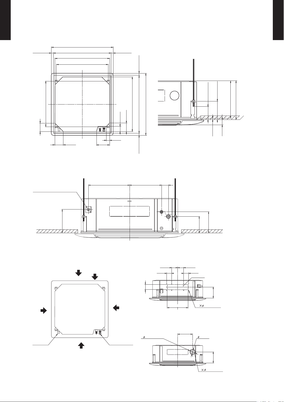
DIMENSIONS4.
MODEL : AUA30L, AUA36L
Ceiling opening and hanging bolt pitch
z
(Unit : mm)
Refrigerant piping and drain piping positions
z
Airow split-ow duct and fresh air inlet positions
z
288 mm
298 mm
40 mm
10 mm
140 - 145 mm
50 - 100 mm
950 mm(Panel frame)
mm 54 - 02mm 54 - 02
50 mm
80 mm
130 mm
130 mm
130 mm
200 mm
840 mm(Body frame)
795 mm(Hanging bolt pitch)
699 mm(Hanging bolt pitch)
860 - 910 mm(Ceiling opening)
950 mm(Panel frame)
mm 54 - 02mm 54 - 02
840 mm(Body frame)
860 - 910 mm(Ceiling opening)
60 mm278 mm358 mm
140 mm
180 mm
200 mm
Drain pipe
(Connect the attached drain hose)
88 mm
70 mm
2.5 mm hole
2.5 mm hole
250 mm
352 mm
100 mm
83 mm83 mm
90 mm
100 mm
mm 581mm 581
Airflow split-flow duct connecting port
Airflow split-flow duct connecting port
Airflow split-flow duct connecting port
Fresh air inlet position
Fresh air inlet position
Drain pipe
Refrigerant pipe
Detailed diagram of branched duct connecting port
(4 sides)
Burling hole pitch
Cut out
Cut out
Airflow split-flow duct connecting port
10
4
Page 9
- (01 - 08) -
CASSETTE TYPE
AU
A30-36L
CASSETTE TYPE
AU
A30-36L
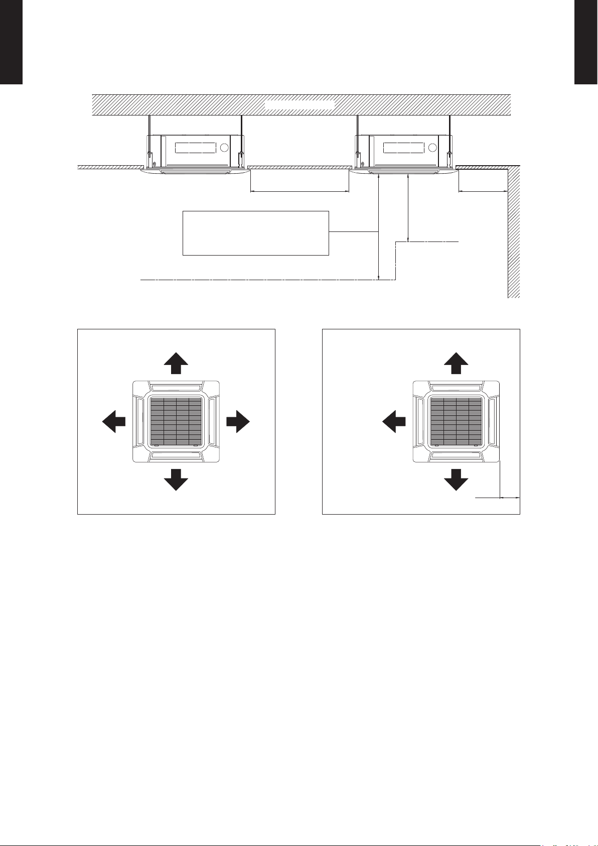
INSTALLATION PLACE
(Unit : mm)
1,500 mm
or more
1,000 mm or more
Obstruction
3,000 mm or more
Strong and durable ceiling
Floor
Ceiling mode “Low” : 2.5 - 2.7 m
Ceiling mode “Standard” : 2.7 - 4.0 m
Ceiling mode “High” : 4.0 - 5.0 m
4 DIRECTION 3 DIRECTION
100 mm
or more
Page 10
- (01 - 09) -
CASSETTE TYPE
AU
A30-36L
CASSETTE TYPE
AU
A30-36L
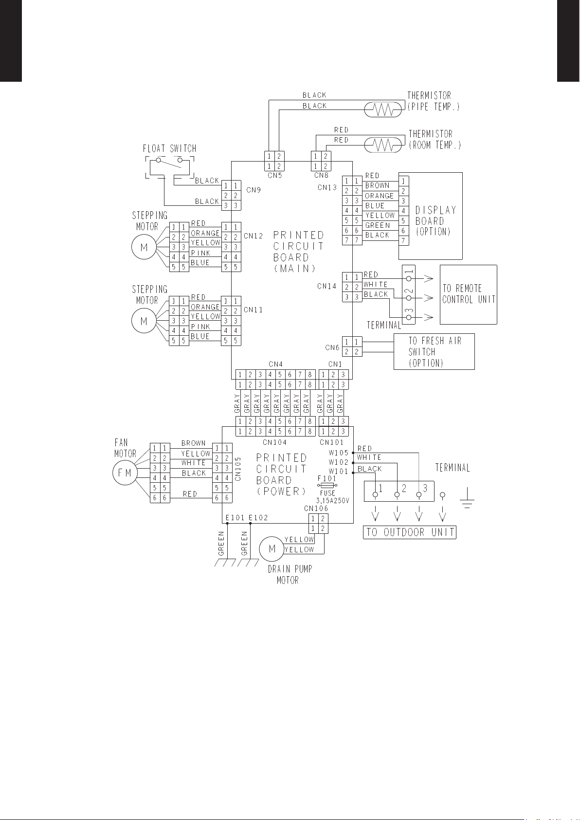
WIRING DIAGRAMS5.
MODEL : AUA30L, AUA36L
Page 11
- (01 - 10) -
CASSETTE TYPE
AU
A30-36L
CASSETTE TYPE
AU
A30-36L
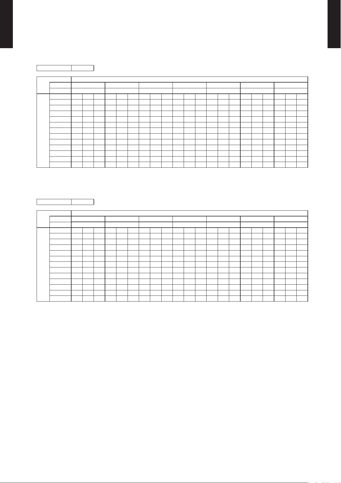
CAPACITY TABLE6.
6-1. COOLING CAPACITY
This table is created using the maximum capacity.
MODEL : AUA30L
MODEL : AU
A36L
AFR : Air ow rate (m3/min)
TC : Total capac ity (kW )
SHC : Sens ible Hea t capac ity (kW )
PI : Power Inp ut (kW)
AFR 26.7
Indoor t emperature
°CDB 18 21 23 25 27 29 32
°CWB 12 15 16 18 19 21 23
Outdoo r temper ature
°CDB TC SHC PI TC SHC PI TC SHC PI TC SHC PI TC SHC PI TC SHC PI TC SHC PI
-15 8.67 6.58 1.20 9.66 6.62 1.22 9.99 7.20 1.22 10.65 7.22 1.24 10.9 8 7.80 1.24 11.64 7.77 1.25 12.2 9 8.27 1.27
-10 8.52 6.38 1.64 9.49 6.42 1.66 9.81 6.98 1.67 10.46 7.00 1.69 10.79 7.56 1.70 11.43 7.53 1.71 12.0 8 8.02 1.73
0 8.12 6 .26 2.11 9.04 6.30 2 .15 9.35 6.85 2.16 9.97 6.87 2.18 10.28 7.42 2.19 10.89 7.39 2.21 11.51 7.87 2.23
5 7.99 6.11 2.14 8.90 6.14 2.17 9.21 6.68 2.19 9.81 6.70 2.21 10.12 7.23 2.2 2 10.72 7.21 2.24 11.33 7.68 2.26
10 7.96 6.19 2.19 8.87 6.23 2.23 9 .17 6 .77 2.24 9.77 6.79 2.26 10.07 7.34 2. 27 10.68 7.31 2.29 11.28 7.78 2.32
15 8.63 6.48 2.41 9.62 6.52 2.45 9.9 4 7.09 2 .46 10.60 7.11 2 .49 10.93 7.68 2.5 0 11.58 7.65 2.53 12.24 8 .14 2.55
20 9.8 2 7.03 2.97 10.94 7.07 3.01 11.31 7.69 3.03 12.06 7. 71 3.06 12.43 8.33 3.08 13.18 8.30 3 .11 13. 92 8.84 3 .14
25 9.4 8 6.89 3.31 10.56 6.93 3.36 10.92 7.53 3.38 11.64 7.56 3. 41 12.00 8.16 3.43 12.72 8 .13 3.46 13.44 8.66 3.50
30 8.81 6.70 3.3 4 9.81 6.74 3.39 10.15 7.32 3. 41 10.81 7.35 3.44 11.15 7.93 3.4 6 11.82 7.90 3.50 12.49 8. 42 3 .53
35 7.90 6.1 2 3.3 5 8 .80 6.16 3.40 9.10 6.69 3.42 9.70 6.71 3 .45 10.00 7.25 3. 47 10.60 7.22 3.51 11.20 7.69 3.5 4
40 6.16 5.13 2. 94 6.86 5.16 2.99 7.09 5.61 3.01 7.56 5.6 3 3.04 7.80 6.08 3.05 8.26 6.05 3.08 8.73 6.4 5 3 .11
46 5.4 4 4 .92 2.91 6.06 4.95 2.96 6. 27 5.39 2.97 6.68 5.40 3.00 6.89 5.8 3 3 .02 7.30 5.81 3.05 7.71 6.19 3.08
AFR 30.0
Indoor t emperature
°CDB 18 21 23 25 27 29 32
°CWB 12 15 16 18 19 21 23
Outdoo r temper ature
°CDB TC SHC PI TC SHC PI TC SHC PI TC SHC PI TC SHC PI TC SHC PI TC SHC PI
-15 9.33 7.37 1.29 10.39 7.41 1.31 10.74 8.06 1.32 11.45 8. 08 1.33 11.80 8.73 1.34 12. 51 8.70 1.35 13.22 9.26 1.36
-10 9.22 7.23 1.69 10.27 7.27 1.71 10.62 7.90 1.72 11.32 7.93 1.74 11.67 8.56 1.75 12.37 8. 53 1.77 13.07 9.08 1.78
0 8.77 7.1 3 2.18 9.77 7.17 2. 22 10.10 7.80 2.23 10.77 7.82 2.25 11.10 8.45 2.26 11.77 8.41 2.29 12.44 8.96 2.31
5 8.69 6 .98 2.25 9.68 7.02 2.28 10.01 7.64 2.29 10.67 7.66 2.32 11.00 8.27 2.33 11.66 8.24 2.35 12.32 8.78 2.38
10 8 .62 7.06 2.25 9.60 7.10 2.2 9 9.93 7.72 2.30 10.58 7.75 2.32 10.91 8.37 2.34 11.56 8.33 2.3 6 12.22 8.88 2.38
15 9.17 7. 17 2.42 10. 21 7.22 2.46 10.56 7.85 2. 47 11.25 7.87 2.50 11.60 8.5 0 2.51 12.30 8.47 2.54 13.00 9.0 2 2 .56
20 10.70 7.92 2.99 11.92 7.97 3.0 3 12.33 8.66 3.05 13.14 8.6 9 3 .08 13.54 9.39 3 .10 14.36 9.35 3 .13 15.17 9.96 3 .16
25 10.6 4 8.02 3.32 11.86 8.0 6 3 .38 12.26 8.77 3.3 9 13.07 8.79 3.43 13.47 9.5 0 3 .45 14.28 9.46 3.4 8 15.09 10.08 3.51
30 10.24 7.7 6 4.05 11.40 7.81 4.11 11.79 8.49 4.13 12.57 8 .51 4.17 12.96 9 .19 4 .19 13.73 9 .16 4.24 14. 51 9.75 4.28
35 8.8 5 6.78 4.03 9.86 6.82 4.10 10.19 7.42 4.1 2 10.8 6 7.44 4 .16 11.20 8.04 4.18 11.87 8.01 4.22 12.54 8.53 4.26
40 6.8 0 5 .96 3.09 7.58 6.00 3 .14 7.84 6.52 3 .16 8 .35 6.54 3.19 8.61 7.07 3.2 0 9.13 7.04 3.24 9.65 7.50 3.27
46 6.11 5.84 2.96 6.81 5.87 3.01 7.04 6.39 3.02 7.50 6 .41 3.05 7. 74 6.92 3.07 8.2 0 6 .89 3.10 8.67 7.34 3 .13
Page 12
- (01 - 11) -
CASSETTE TYPE
AU
A30-36L
CASSETTE TYPE
AU
A30-36L
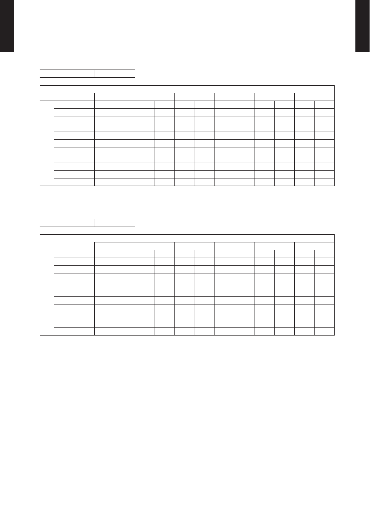
6-2. HEATING CAPACITY
This table is created using the maximum capacity.
MODEL : AUA30L
MODEL : AUA36L
AFR : Air ow rate (m3/min)
TC : Total capac ity (kW )
PI : Power Inpu t (kW)
AFR 26.7
Indoor temperature
°CDB 16 18 20 22 24
Outdoor temperature
°CDB °CWB TC PI TC PI TC PI TC PI TC PI
-15 -16 8.34 3.37 8.14 3.44 7.94 3.51 7.75 3.58 7.55 3.65
-10 -11 8.79 3.38 8.58 3.45 8.37 3.52 8.16 3.59 7.95 3.66
-5 -7 9.55 3.41 9.32 3.48 9.09 3.55 8.86 3.62 8.64 3.69
0 -2 10.12 3.37 9.88 3.44 9.64 3.51 9.40 3.58 9.16 3.65
5 3 11. 23 3.35 10.96 3.42 10.69 3.49 10.43 3.56 10.16 3.62
7 6 11.76 3.33 11.48 3.40 11.20 3.47 10.92 3.54 10.6 4 3.61
10 8 12.12 3.30 11.83 3.37 11. 54 3.44 11.25 3.51 10.96 3.57
15 10 10.86 2.52 10.60 2.57 10.34 2.62 10.09 2.67 9.83 2.71
20 15 10.87 2.23 10.61 2.28 10.35 2.33 10.09 2.37 9.83 2.41
24 18 11.31 2.25 11. 04 2.30 10.78 2.34 10.51 2.39 10.24 2.43
AFR 30.0
Indoor temperature
°CDB 16 18 20 22 24
Outdoor temperature
°CDB °CWB TC PI TC PI TC PI TC PI TC PI
-15 -16 9.63 3.92 9.40 4.00 9.17 4.08 8.94 4.17 8.71 4.25
-10 -11 9.70 3.96 9.47 4.04 9.24 4.13 9.01 4.21 8.77 4.29
-5 -7 10.69 4.07 10.43 4.16 10.18 4.24 9.92 4.33 9.67 4.41
0 -2 12.5 4 3.99 12.24 4.08 11.9 4 4.16 11.64 4.24 11 .34 4.33
5 3 13 .18 3.81 12.87 3.89 12.55 3.97 12. 24 4.05 11.92 4.13
7 6 13.34 3.36 13.02 3.43 12.70 3.50 12.38 3.57 12.07 3.64
10 8 13.74 3.19 13.42 3. 26 13.09 3.33 12.76 3.39 12.43 3.46
15 10 12.26 2.55 11.97 2.60 11.67 2.65 11.38 2.71 11.09 2.75
20 15 12.28 2.26 11.99 2.31 11.6 9 2.36 11.40 2.40 11.11 2.44
24 18 12.80 2.28 12.49 2.32 12.19 2.37 11.88 2.42 11. 58 2.46
Page 13

- (01 - 12) -
CASSETTE TYPE
AU
A30-36L
CASSETTE TYPE
AU
A30-36L
FAN PERFORMANCE7.
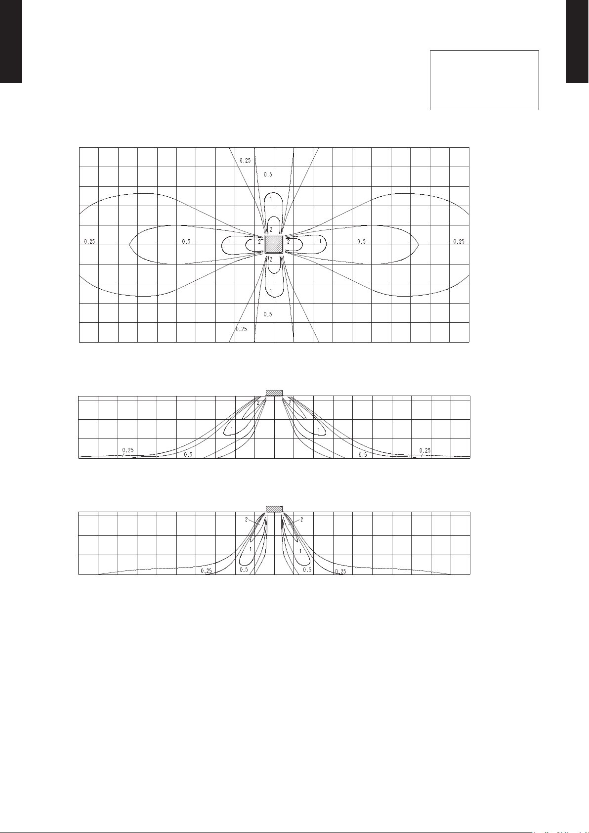
7-1. AIR VELOCITY DISTRIBUTION
7-1-1. STANDARD MODE
MODEL : AUA30L
4-way air outlet
z
Note:
Condition
Fan speed : High
Operation mode : FAN
Ceiling mode : Standard
5
4
3
2
1
0
1
2
3
4
5
Unit : m/s(m)
(m)
TOP VIEW
HORIZO NTAL LOUVER
: Upwar d
3.2
2
1
0
Unit : m/s(m)
(m)
SIDE VI EW
HORIZO NTAL LOUVER
: Upwar d
3.2
2
1
0
Unit : m/s(m)
(m)
SIDE VI EW
HORIZO NTAL LOUVER
: Downwar d
10 9 8 7 6 5 4 3 2 1 0 1 2 3 4 5 6 7 8 9 10
10 9 8 7 6 5 4 3 2 1 0 1 2 3 4 5 6 7 8 9 10
10 9 8 7 6 5 4 3 2 1 0 1 2 3 4 5 6 7 8 9 10
Page 14
- (01 - 13) -
CASSETTE TYPE
AU
A30-36L
CASSETTE TYPE
AU
A30-36L
MODEL : AUA36L
4-way air outlet
z
Note:
Condition
Fan speed : High
Operation mode : FAN
Ceiling mode : Standard
5
4
3
2
1
0
1
2
3
4
5
Unit : m/s(m)
(m)
TOP VIEW
HORIZO NTAL LOUVER
: Upwar d
3.2
2
1
0
Unit : m/s(m)
(m)
SIDE VI EW
HORIZO NTAL LOUVER
: Upwar d
3.2
2
1
0
Unit : m/s(m)
(m)
SIDE VI EW
HORIZO NTAL LOUVER
: Downwar d
10 9 8 7 6 5 4 3 2 1 0 1 2 3 4 5 6 7 8 9 10
10 9 8 7 6 5 4 3 2 1 0 1 2 3 4 5 6 7 8 9 10
10 9 8 7 6 5 4 3 2 1 0 1 2 3 4 5 6 7 8 9 10
Page 15

- (01 - 14) -
CASSETTE TYPE
AU
A30-36L
CASSETTE TYPE
AU
A30-36L
MODEL : AUA30L
3-way air outlet
z
Note:
Condition
Fan speed : High
Operation mode : FAN
Ceiling mode : Standard
5
4
3
2
1
0
1
2
3
4
5
Unit : m/s(m)
(m)
TOP VIEW
HORIZO NTAL LOUVER
: Upwar d
3.2
2
1
0
Unit : m/s(m)
(m)
SIDE VI EW
HORIZO NTAL LOUVER
: Upwar d
3.2
2
1
0
Unit : m/s(m)
(m)
SIDE VI EW
HORIZO NTAL LOUVER
: Downwar d
10 9 8 7 6 5 4 3 2 1 0 1 2 3 4 5 6 7 8 9 10
10 9 8 7 6 5 4 3 2 1 0 1 2 3 4 5 6 7 8 9 10
10 9 8 7 6 5 4 3 2 1 0 1 2 3 4 5 6 7 8 9 10
Page 16

- (01 - 15) -
CASSETTE TYPE
AU
A30-36L
CASSETTE TYPE
AU
A30-36L
MODEL : AUA36L
3-way air outlet
z
Note:
Condition
Fan speed : High
Operation mode : FAN
Ceiling mode : Standard
5
4
3
2
1
0
1
2
3
4
5
Unit : m/s(m)
(m)
TOP VIEW
HORIZO NTAL LOUVER
: Upwar d
3.2
2
1
0
Unit : m/s(m)
(m)
SIDE VI EW
HORIZO NTAL LOUVER
: Upwar d
3.2
2
1
0
Unit : m/s(m)
(m)
SIDE VI EW
HORIZO NTAL LOUVER
: Downwar d
10 9 8 7 6 5 4 3 2 1 0 1 2 3 4 5 6 7 8 9 10
10 9 8 7 6 5 4 3 2 1 0 1 2 3 4 5 6 7 8 9 10
10 9 8 7 6 5 4 3 2 1 0 1 2 3 4 5 6 7 8 9 10
Page 17

- (01 - 16) -
CASSETTE TYPE
AU
A30-36L
CASSETTE TYPE
AU
A30-36L
7-1-2. SPECIAL UPWARD MODE
MODEL : AUA30L
4-way air outlet
z
MODEL : AUA36L
4-way air outlet
z
Note:
Condition
Fan speed : High
Operation mode : FAN
Ceiling mode : Standard
10 9 8 7 6 5 4 3 2 1 0 1 2 3 4 5 6 7 8 9 10
10 9 8 7 6 5 4 3 2 1 0 1 2 3 4 5 6 7 8 9 10
(m)
Unit : m/s
3.2
2
1
0
(m)
SIDE VI EW
HORIZO NTAL LOUVER
: S pecial u pward
(m)
SIDE VI EW
HORIZO NTAL LOUVER
: S pecial u pward
Unit : m/s(m)
3.2
2
1
0
Page 18

- (01 - 17) -
CASSETTE TYPE
AU
A30-36L
CASSETTE TYPE
AU
A30-36L
7-2. AIR FLOW
7-2-1. 4-WAY OUTLET
MODEL : AUA30L
Cooling / Heating
z
MODEL : AU
A36L
Cooling / Heating
z
Fan speed
Number of
rotations
(r.p.m)
Airow
HIGH 570
m
3
/h 1600
l/s 444
CFM 942
MED 510
m
3
/h 1400
l/s 389
CFM 824
LOW 470
m
3
/h 1270
l/s 353
CFM 747
QUIET 420
m
3
/h 1150
l/s 319
CFM 677
Fan speed
Number of
rotations
(r.p.m)
Airow
HIGH 640
m
3
/h 1800
l/s 500
CFM 1059
MED 510
m
3
/h 1400
l/s 389
CFM 824
LOW 470
m
3
/h 1270
l/s 353
CFM 747
QUIET 420
m
3
/h 1150
l/s 319
CFM 677
Page 19

- (01 - 18) -
CASSETTE TYPE
AU
A30-36L
CASSETTE TYPE
AU
A30-36L
7-2-2. 3-WAY OUTLET
MODEL : AUA30L
Cooling / Heating
z
MODEL : AU
A36L
Cooling / Heating
z
*Air ow can be changed according to the direction in which the outlet is blocked.
Fan speed
Number of
rotations
(r.p.m)
Airow
*Max. *Min.
HIGH 610
m
3
/h 1550 1350
l/s 431 375
CFM 912 794
MED 550
m
3
/h 1350 1200
l/s 375 333
CFM 794 706
LOW 510
m
3
/h 1250 1100
l/s 347 306
CFM 736 647
QUIET 460
m
3
/h 1100 950
l/s 306 264
CFM 647 559
Fan speed
Number of
rotations
(r.p.m)
Airow
*Max. *Min.
HIGH 680
m
3
/h 1700 1550
l/s 472 431
CFM 1000 912
MED 550
m
3
/h 1350 1200
l/s 375 333
CFM 794 706
LOW 510
m
3
/h 1250 1100
l/s 347 306
CFM 736 647
QUIET 460
m
3
/h 1100 950
l/s 306 264
CFM 647 559
Page 20

- (01 - 19) -
CASSETTE TYPE
AU
A30-36L
CASSETTE TYPE
AU
A30-36L
7-3. FRESH AIR
MODEL : AUA30L, AUA36L
7-4. DUCT CONNECTION
MODEL : AUA30L, AUA36L
Outlet air
z
Fan speed High
Fan speed
Qutiet
L=10m
L=5m
L=1m
Fan speed High
Fan speed
Quiet
L=10m
L=5m
L=1m
98
49
0
98
49
0
10
9
8
7
6
5
4
3
2
1
0
10
9
8
7
6
5
4
3
2
1
0
0 2 4 6 8 10 12 14
0 2 4 6 8 10 12 14
AUA30L
AUA36L
Air ow (m3/min)
Air ow (m3/min)
Duct
(Inside Dia. 350mm×100mm)
L
Duct
(Inside Dia. ø70mm)
Static pressure required
to take in fresh air
Duct Fan
Duct static pressure (Pa)Duct static pressure (Pa)
Duct static pressure (mmAq)Duct static pressure (mmAq)
98
49
0
10
8
6
4
2
0
0 0.1 0.2 0.3 0.4 0.5 0.6 0.7
Air ow (m3/min)
Duct static pressure (Pa)
Duct static pressure (mmAq)
Page 21

- (01 - 20) -
CASSETTE TYPE
AU
A30-36L
CASSETTE TYPE
AU
A30-36L
OPERATION NOISE8.
8-1. NOISE LEVEL CURVE
MODEL : AUA30L
Condition
Ceiling mode : Standard
Air outlet : 4-way air outlet
HIGH
QUIET
Octave band soun d pressu re level, dB:(0dB= 0.00 02µbar)
Octave band center frequ ency,Hz
80
70
60
50
40
30
20
10
0
63 125 250 500 1,000 2,00 0 4,000 8,000
MODEL : AUA36L
Cooling
z
NC-65
NC-60
NC-55
NC-50
NC-45
NC-40
NC-35
NC-30
NC-25
NC-20
NC -15
Heating
z
Octave band soun d pressu re level, dB:(0dB= 0.00 02µbar)
Octave band center frequ ency,Hz
80
70
60
50
40
30
20
10
0
63 125 250 50 0 1,000 2,0 00 4,000 8,000
NC-65
NC-60
NC-55
NC-50
NC-45
NC-40
NC-35
NC-30
NC-25
NC-20
NC -15
Heating
z
Octave band soun d pressu re level, dB:(0dB= 0.00 02µbar)
Octave band center frequ ency,Hz
80
70
60
50
40
30
20
10
0
63 125 250 50 0 1,000 2,0 00 4,000 8,000
NC-65
NC-60
NC-55
NC-50
NC-45
NC-40
NC-35
NC-30
NC-25
NC-20
NC -15
HIGH
QUIET
HIGH
QUIET
HIGH
QUIET
Cooling
z
Octave band soun d pressu re level, dB:(0dB= 0.00 02µbar)
Octave band center frequ ency,Hz
80
70
60
50
40
30
20
10
0
63 125 250 50 0 1,000 2,0 00 4,000 8,000
NC-65
NC-60
NC-55
NC-50
NC-45
NC-40
NC-35
NC-30
NC-25
NC-20
NC -15
Page 22

- (01 - 21) -
CASSETTE TYPE
AU
A30-36L
CASSETTE TYPE
AU
A30-36L
8-2. SOUND LEVEL CHECK POINT
Microphone
Microphone
CENTER
1.5m
Page 23

- (01 - 22) -
CASSETTE TYPE
AU
A30-36L
CASSETTE TYPE
AU
A30-36L
ELECTRIC CHARACTERISTICS9.
Model Name AUA30L AUA36L
Power Supply
Voltage V 230V ~
Frequency Hz 50Hz
Max Operating Current (Indoor unit) A 0.7
Wiring Spec.
(Indoor unit to outdoor unit)
Circuit breaker A 0.8
Connection Cable mm
2
1.5-2.5
Limited wiring length m 51
Page 24

- (01 - 23) -
CASSETTE TYPE
AU
A30-36L
CASSETTE TYPE
AU
A30-36L
SAFETY DEVICES10.
Protection form
Model
AUA30L AUA36L
Circuit protection Current fuse (PCB) 3.15A 250V
Fan motor protection
Thermal protection
program
110±15°C OFF
105±15°C ON
Page 25

- (01 - 24) -
CASSETTE TYPE
AU
A30-36L
CASSETTE TYPE
AU
A30-36L
OPTIONAL PARTS11.
Exterior Parts name Model No. Summary
Decoration
panel
UTG-UGA-W
Ceiling dirt by discharged wind
was made difcult to cling by
reviewing the shape of the
LOUVER.
Air outlet
shutter plate
UTR-Y DZC
Air outlet shutter plate is
installed at the air outlet when
3-way direction is performed.
Indoor unit
950
Panel
600
600 (mm)
Wide panel UTG -AGYA- W
Wide panel hides the gap
between the ceiling hole and
the Decoration panel.
Panel spacer
242mm
56mm
Panel spacer U TG - BGYA-W
Installation in a space of
256mm or greater is possible
by using panel spacer when
the height behind the ceiling is
low.
(Normal behind the ceiling
installation height is 298mm.)
IR Receiver kit UT Y- LRHA1
Unit control is performed by
wireless remote controller
Wired remote
controller
UTB-UD
Unit control is performed by
wired remote controller
Page 26

R410A
D2D_AO022E/01
2008.01.24
2.
SINGLE TYPE :
AO A30LBTL
AO A36LBTL
OUTDOOR UNIT
Page 27

- (02 - 01) -
1. SPECIFICATIONS
OUTDOOR UNIT
AO A30-36L
OUTDOOR UNIT
AO A30-36L
AO A30LBTL AO A36LBTL
Power source
Available voltage range
A 15.0 15.0
Cooling 3600 4000
Heating 3800 3800
Type × Q'ty
Motor output W 103 103
Cooling 53 54
Heating 55 55
Dimensions (H × W × D)
798 × 900 × 36.4 798 × 900 × 36.4
Fin pitch 1.30 1.30
Rows x Stages 2 × 38 2 × 38
Pipe type
Fin type
Motor output W
Charge g
Material
Colour
Net
Gross
Net
Gross
Liquid
Gas
Method
Max. length 50(chargeless:20) 50(chargeless:20)
Max. height difference 30 30
Cooling
Heating
Note :
Specifications are based on the following conditions.
Cooling : Indoor temperature of 27 °CDB / 19 °CWB.and outdoor temperature of 35 °CDB/24 °CWB.
Heating : Indoor temperature of 20 °CDB / 15 °CWB.and outdoor temperature of 7 °CDB/6 °CWB.
Pipe length : 5 m, Height difference : 0 m.(Outdoor unit - Indoor unit)
°C
Operation range
Type
Model name
Fan
Airflow
rate
m3/h
dB(A)
mm
mm
Weight
kg(lb.)
Dimensions
(H × W × D)
Refrigerant oil
Type
Enclosure
Heat exchanger type
Starting current
Compressor
Type × Q'ty
Refrigerant
Type
Sound pressure level
m
Connection pipe
Size
mm
INVERTER HEATPUMP
230V 50Hz
198-264V 50Hz
Propeller × 1
9.52 ( 3/8 in.)
Copper
Aluminium
Steel sheet
Beige (10YR7.5/1.0NN)
Twin Rotary × 1
1700
R410A
PVE
2100
15.88 ( 5/8 in.)
Flare
-15 to 46
-15 to 24
830 × 900 × 330
62 ( 136 )
70 ( 154 )
970 × 1050 × 445
Page 28

- (02 - 02) -
2. DIMENSIONS
MODEL : AO A30L, AO A36L
MOUNTING POSITION
(Unit : mm)
When there are obstacles at the
back or front sides.
When there are obstacles at the
back, side(s), and top.
When there are obstacles at the
back, side with the installation of
more than one unit.
603
Air flow
900
650
830
370
99
196
21
9
77
31 330
400
170
147
12
600 mm
or more
250 mm
or more
250 mm
or more
300 mm
or more
600 mm or more
100 mm
or more
300 mm
or more
100 mm
or more
250 mm or more
(Service space)
Top view
Front view
Side view
Bottom view
OUTDOOR UNIT
AO A30-36L
OUTDOOR UNIT
AO A30-36L
Page 29
- (02 - 03) -
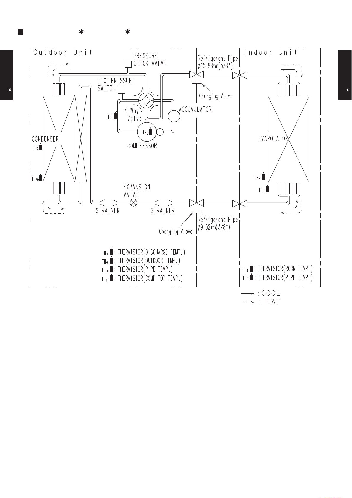
3. REFRIGERANT CIRCUIT
MODEL : AO A30L, AO A36L
OUTDOOR UNIT
AO A30-36L
OUTDOOR UNIT
AO A30-36L
Page 30

- (02 - 04) -
4. WIRING DIAGRAMS
MODEL : AO A30L, AO A36L
OUTDOOR UNIT
AO A30-36L
OUTDOOR UNIT
AO A30-36L
Page 31
- (02 - 05) -
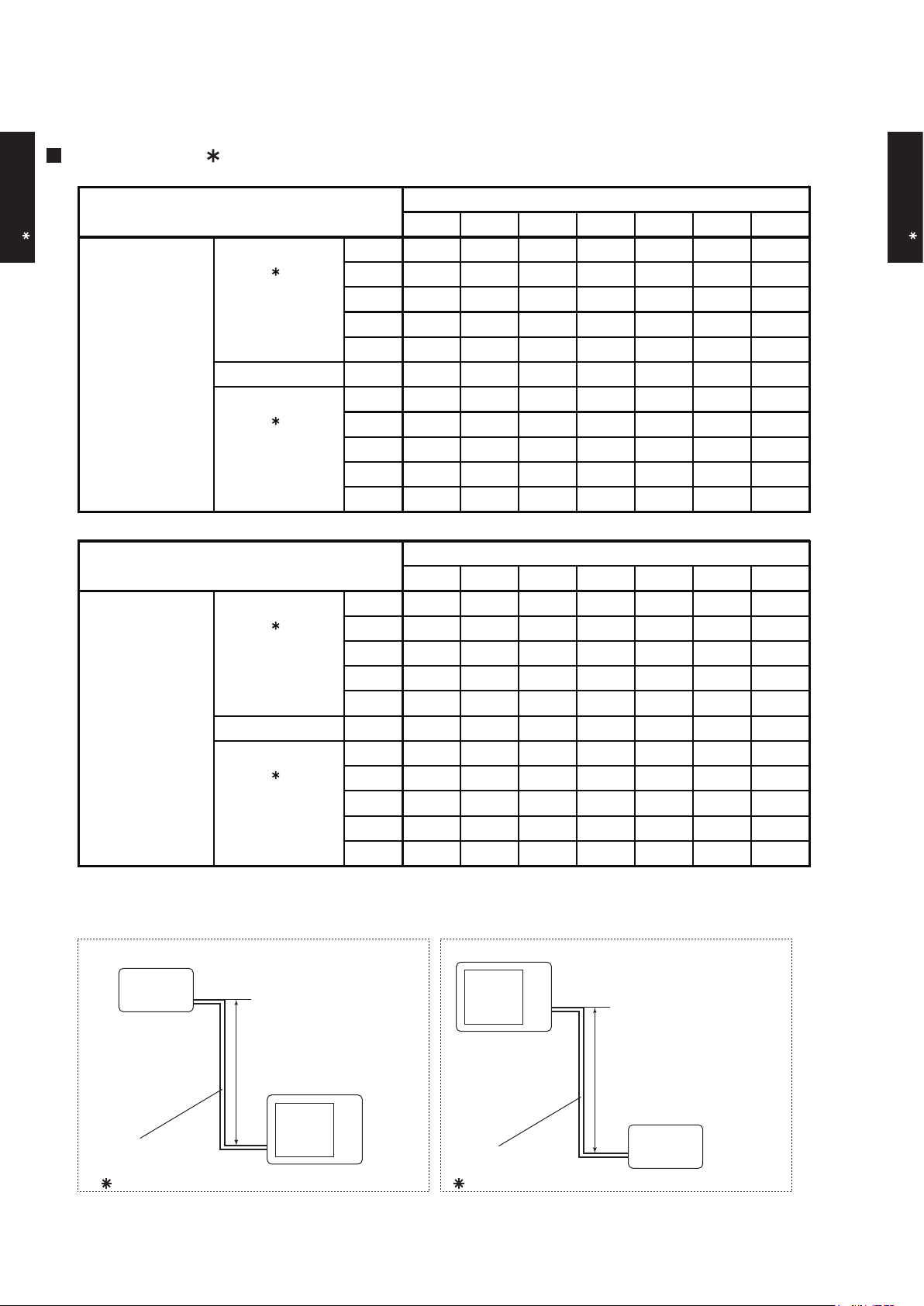
5. COEFFICIENT OF COMPENSATION FOR PIPE LENGTH
AND HEIGHT DIFFERENCE
MODEL : AO A30L
Indoor unit
Height difference H
Connection pipe
H
Outdoor unit
Indoor unit
Connection pipe
H
Outdoor unit
Indoor unit is upper than outdoor unit.
1
Indoor unit is under than outdoor unit.
2
This table is created using the maximum capacity.
OUTDOOR UNIT
AO A30-36L
OUTDOOR UNIT
AO A30-36L
5 7.5 10 20 30 40 50
30 - - - - 0.931 0.914 0.899
20 - - - 0.954 0.931 0.914 0.899
10 - - 0.990 0.954 0.931 0.914 0.899
7.5 - 0.991 0.990 0.954 0.931 0.914 0.899
5 1.000 0.991 0.990 0.954 0.931 0.914 0.899
0 1.000 0.991 0.990 0.954 0.931 0.914 0.899
-5 0.995 0.986 0.986 0.949 0.926 0.909 0.895
-7.5 - 0.983 0.983 0.946 0.924 0.907 0.892
-10 - - 0.981 0.944 0.921 0.904 0.890
-20 - - - 0.935 0.912 0.895 0.881
-30 - - - - 0.903 0.886 0.872
Height difference H
(m)
1
Indoor unit is
upper than
outdoor unit
2
Indoor unit is
under than
outdoor unit.
Pipe length (m)
HEATING
5 7.5 10 20 30 40 50
30 - - - - 0.908 0.894 0.876
20 - - - 0.935 0.923 0.909 0.891
10 - - 0.968 0.951 0.938 0.924 0.906
7.5 - 0.982 0.972 0.954 0.942 0.928 0.909
5 0.992 0.986 0.976 0.958 0.946 0.932 0.913
0 1.000 0.994 0.983 0.966 0.954 0.939 0.920
-5 1.000 0.994 0.983 0.966 0.954 0.939 0.920
-7.5 - 0.994 0.983 0.966 0.954 0.939 0.920
-10 - - 0.983 0.966 0.954 0.939 0.920
-20 - - - 0.966 0.954 0.939 0.920
-30 - - - - 0.954 0.939 0.920
Pipe length (m)
COOLING
1
Indoor unit is
upper than
outdoor unit
2
Indoor unit is
under than
outdoor unit.
Height difference H
(m)
Page 32

- (02 - 06) -
MODEL : AO A36L
Indoor unit
Height difference H
Connection pipe
H
Outdoor unit
Indoor unit
Connection pipe
H
Outdoor unit
Indoor unit is upper than outdoor unit.
1
Indoor unit is under than outdoor unit.
2
This table is created using the maximum capacity.
OUTDOOR UNIT
AO A30-36L
OUTDOOR UNIT
AO A30-36L
5 7.5 10 20 30 40 50
30 - - - - 0.908 0.894 0.876
20 - - - 0.935 0.923 0.909 0.891
10 - - 0.968 0.951 0.938 0.924 0.906
7.5 - 0.982 0.972 0.954 0.942 0.928 0.909
5 0.992 0.986 0.976 0.958 0.946 0.932 0.913
0 1.000 0.994 0.983 0.966 0.954 0.939 0.920
-5 1.000 0.994 0.983 0.966 0.954 0.939 0.920
-7.5 - 0.994 0.983 0.966 0.954 0.939 0.920
-10 - - 0.983 0.966 0.954 0.939 0.920
-20 - - - 0.966 0.954 0.939 0.920
-30 - - - - 0.954 0.939 0.920
COOLING
1
Indoor unit is
upper than
outdoor unit
2
Indoor unit is
under than
outdoor unit.
Height difference H
(m)
Pipe length (m)
5 7.5 10 20 30 40 50
30 - - - - 0.931 0.914 0.899
20 - - - 0.954 0.931 0.914 0.899
10 - - 0.990 0.954 0.931 0.914 0.899
7.5 - 0.991 0.990 0.954 0.931 0.914 0.899
5 1.000 0.991 0.990 0.954 0.931 0.914 0.899
0 1.000 0.991 0.990 0.954 0.931 0.914 0.899
-5 0.995 0.986 0.986 0.949 0.926 0.909 0.895
-7.5 - 0.983 0.983 0.946 0.924 0.907 0.892
-10 - - 0.981 0.944 0.921 0.904 0.890
-20 - - - 0.935 0.912 0.895 0.881
-30 - - - - 0.903 0.886 0.872
HEATING
Pipe length (m)
Height difference H
(m)
1
Indoor unit is
upper than
outdoor unit
2
Indoor unit is
under than
outdoor unit.
Page 33

- (02 - 07) -
6. ADDITIONAL CHARGE CALCULATION
MODEL : AO A30L, AO A36L
REFRIGERANT CHARGE
Refrigerant type
Refrigerant amount g
Pipe length m 20 30 40 50
Additional charge g 0 (Chargeless) +400 +800 +1200
R410A
2100
40g/m
OUTDOOR UNIT
AO A30-36L
OUTDOOR UNIT
AO A30-36L
Page 34

- (02 - 08) -
MODEL : AO A30L
7. AIR FLOW
COOLING
HEATING
MODEL : AO A36L
COOLING
HEATING
m3/h
3600
l/s 1000
CFM 2119
m3/h
3800
l/s 1056
CFM 2236
m3/h
4000
l/s 1111
CFM 2354
m3/h
3800
l/s 1056
CFM 2236
Airflow
950
Airflow
900
Number of
rotations
(r.p.m)
Number of
rotations
(r.p.m)
850
900
Airflow
Airflow
Number of
rotations
(r.p.m)
Number of
rotations
(r.p.m)
OUTDOOR UNIT
AO A30-36L
OUTDOOR UNIT
AO A30-36L
Page 35

- (02 - 09) -
8-1. NOISE LEVEL CURVE
8. OPERATION NOISE
COOLING
Octave band sound pressure level, dB:(0dB=0.0002µbar)
Octave band center frequency,Hz
0
10
20
30
40
50
60
70
80
Octave band sound pressure level, dB:(0dB=0.0002µbar)
0
10
20
30
40
50
60
70
80
63 125 250 500 1,000 2,000 4,000 8,000
Octave band center frequency,Hz
63 125 250 500 1,000 2,000 4,000 8,000
COOLING
Octave band sound pressure level, dB:(0dB=0.0002µbar)
Octave band center frequency,Hz
0
10
20
30
40
50
60
70
80
63 125 250 500 1,000 2,000 4,000 8,000
HEATING
Octave band sound pressure level, dB:(0dB=0.0002µbar)
Octave band center frequency,Hz
0
10
20
30
40
50
60
70
80
63 125 250 500 1,000 2,000 4,000 8,000
HEATING
MODEL : AO A30L
MODEL : AO A36L
NC-20
NC-40
NC-50
NC-60
NC-30
NC-15
NC-25
NC-35
NC-45
NC-55
NC-65
NC-20
NC-40
NC-50
NC-60
NC-30
NC-15
NC-25
NC-35
NC-45
NC-55
NC-65
NC-20
NC-40
NC-50
NC-60
NC-30
NC-15
NC-25
NC-35
NC-45
NC-55
NC-65
NC-20
NC-40
NC-50
NC-60
NC-30
NC-15
NC-25
NC-35
NC-45
NC-55
NC-65
OUTDOOR UNIT
AO A30-36L
OUTDOOR UNIT
AO A30-36L
Page 36

- (02 - 10) -
OUTDOOR UNIT
AO A30-36L
OUTDOOR UNIT
AO A30-36L
8-2. SOUND LEVEL CHECK POINT
Page 37

- (02 - 11) -
9. ELECTRIC CHARACTERISTICS
OUTDOOR UNIT
AO A30-36L
OUTDOOR UNIT
AO A30-36L
Model name
AO A30L AO A36L
Voltage V
Frequency Hz
Max. operating current A 17.0 20.0
Starting current A
Main fuse (Circuit breaker)
current
A
Power cable
mm
2
*2)Limited wiring length m 21 18
*1) Wiring spec.
Selected sample
(Selected based on Japan Electrotechnical Standard and Codes Committee E0005)
*2) Limited wiring length :
This is the wiring length in case voltage descent is less than 2%.
When the wiring length becomes long, please select the wiring of a more larger diameter.
15.0
Power supply
*1) Wiring spec.
230
50
4.0
30
Page 38

- (02 - 12) -
10. SAFETY DEVICES
AO A30L AO A36L
Current fuse
(NEAR THE TERMINAL)
Current fuse
(FILTER PRINTED CIRCUIT BOARD)
Current fuse
(MAIN PRINTED CIRCUIT BOARD)
Fan motor protection Thermal protection program
High Pressure Protection Pressure Switch
Thermal protection program
(COMPRESSOR TEMP.)
Thermal protection program
(DISCHARGE TEMP.)
Protection form
25A 250V
10A 250V
Model
3.15A 250V
Compressor protection
Circuit protection
OFF : 120°C
ON : 80°C
OFF : 110°C
ON : After 7 minutes
OFF : 140±20°C
ON : 110±20°C
OFF : 4.2±0.1MPa
ON : 3.2±0.15MPa
OUTDOOR UNIT
AO A30-36L
OUTDOOR UNIT
AO A30-36L
 Loading...