

Page 1
R410A
INDOOR UNIT
1. CASSETTE
AU A18LAL
AU F18LAL
AU A24LAL
AU A24LBL
TYPE :
D2D_AU030E/04
2008.04.08
Page 2
1. FEATURE
MODEL :
CASSETTE TYPE
AU A18-24L
INDOOR UNIT
OUTDOOR UNIT
AU A18LAL AO A18LACL AO B18LACL
AU F18LAL AO A18LALL AO B18LALL
AU A24LAL AO A24LACL AO B24LACL
AU A24LBL AO A24LALL AO B24LALL
FEATURES
ENERGY SAVING (AO A18LACL, AO A18LALL, AO A24LACL, AO A24LALL connection model)
• ALL DC DESIGN
• Heat exchange efficiency increased and larger air flow by adoption of new type turbo fan
ADVANCEMENT IN COMFORT
• Quiet operation was realized by adoption of new type turbo fan
• Improvement of air stream
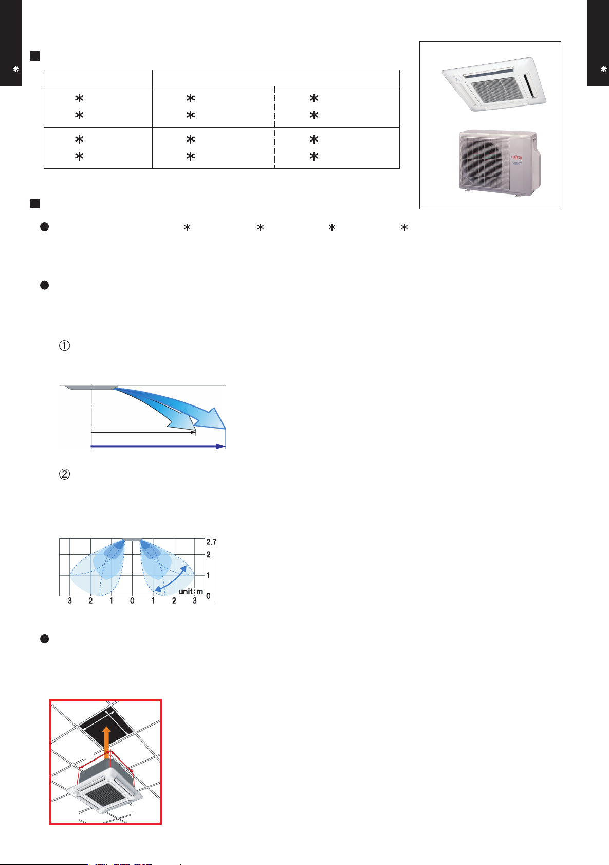
IMPROVEMENT IN AIRFLOW RANGE (18 TYPE)
*Wind velocity at maximum point of airflow range is 0.5m/s
CASSETTE TYPE
AU A18-24L
Conventional type
New type
2.5 m
3.7 m
EXPANSION OF AIR OUTLET ADJUSTMENT RANGE (18 TYPE)
Auto airflow direction and auto swing
Expanded air outlet range provides more comfortable space
New type
IMPROVEMENT OF INSTALLATION & MAINTENANCE
• COMPACT DESIGN
Fits the European size ceiling.
New type
590
590
18 type
18 type
18kg
18kg
570
570
24 type
24 type
19kg
19kg
- (01 - 01) -
Page 3
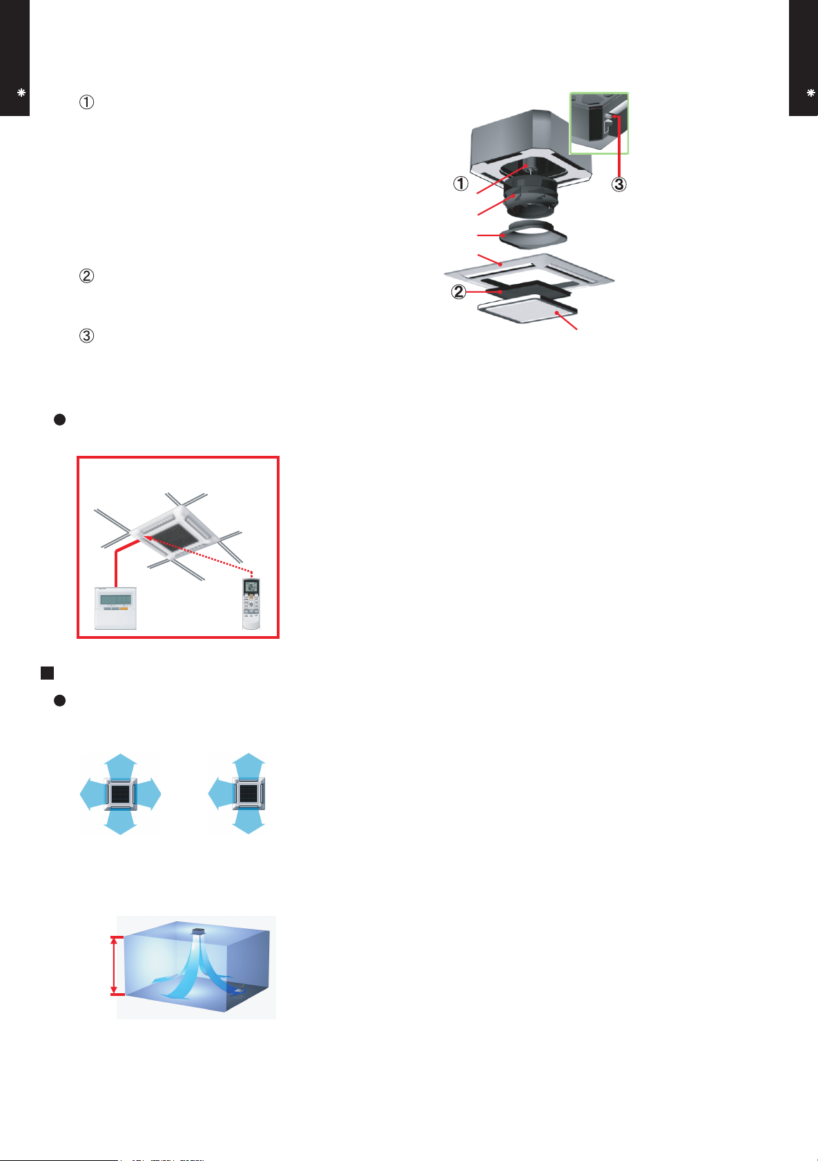
• EASY MAINTENANCE
CASSETTE TYPE
AU A18-24L
Maintenance of fan motor and fan
Maintenance of fan motor and fan can be done
easily after taking off the panel,
since bell-mouth can be removed easily
A : Fan motor
B : 2 stage turbo fan
C : Bell-mouth
D : Panel
Long life filter
: standard equipment
Adaptation of transparent drainage parts
Easy check of operation of drain-up kit
When you install
EASY INSTALLATION
New type
Easy setting by wireless or
wired remote controller
CASSETTE TYPE
AU A18-24L
A
B
C
D
Grille cover
FUNCTION SETTING
OTHER FUNCTIONS
• The number of air outlet can be selected.
4-way direction 3-way direction
• High ceiling mode
Air reaches sufficiently up to 3.5m height, even it is compact cassette type.
High ceiling
3.5m
• Setting the filter sign
The indoor unit has sign to inform the user that it is time to clean the filter
• Setting the cooler room temperature correction
• Setting the heater room temperature correction
• Auto restart
- (01 - 02) -
Page 4
1 2
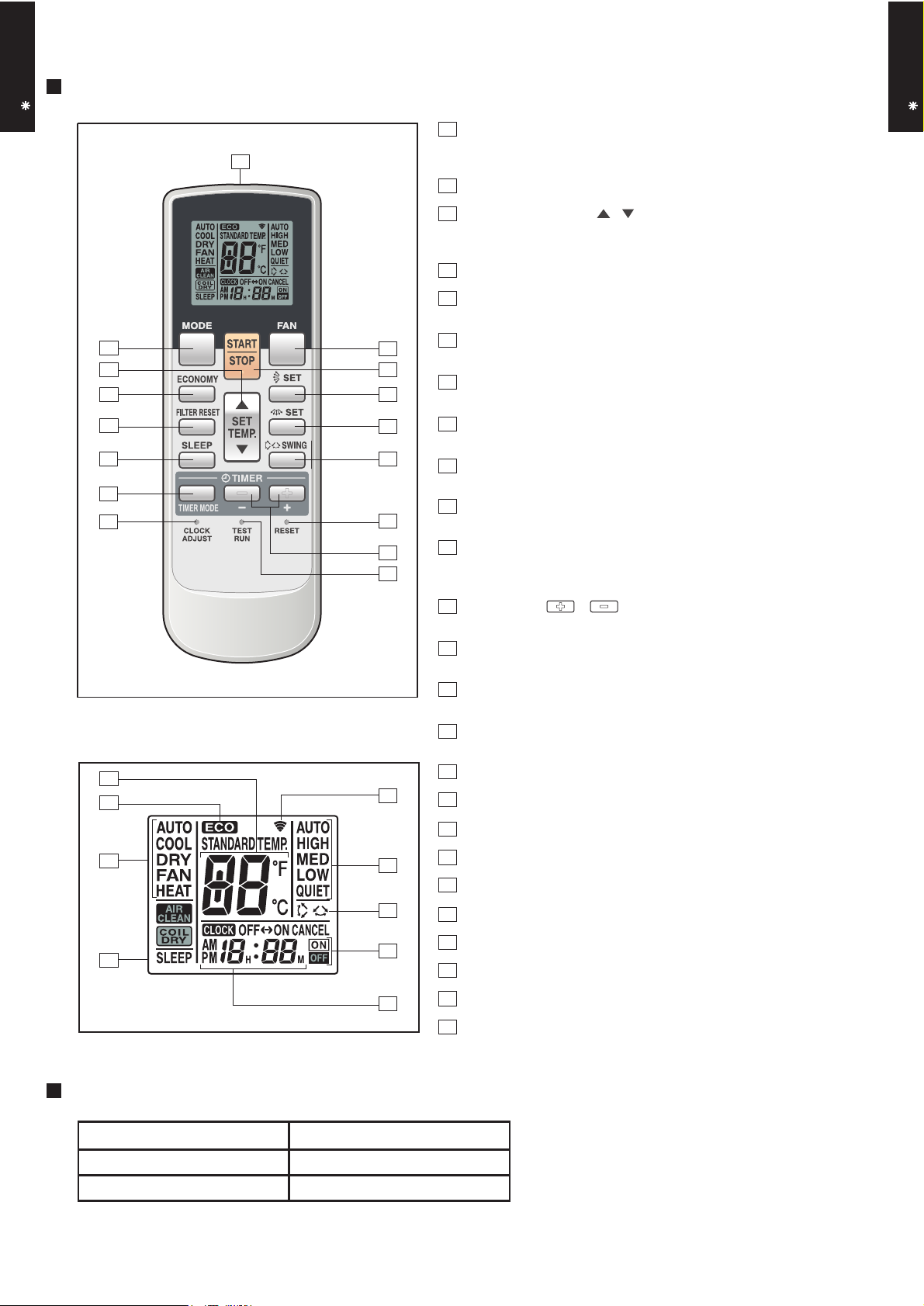
2. REMOTE CONTROLLER
WIRELESS REMOTE CONTROLLER
CASSETTE TYPE
AU A18-24L
FEATURES
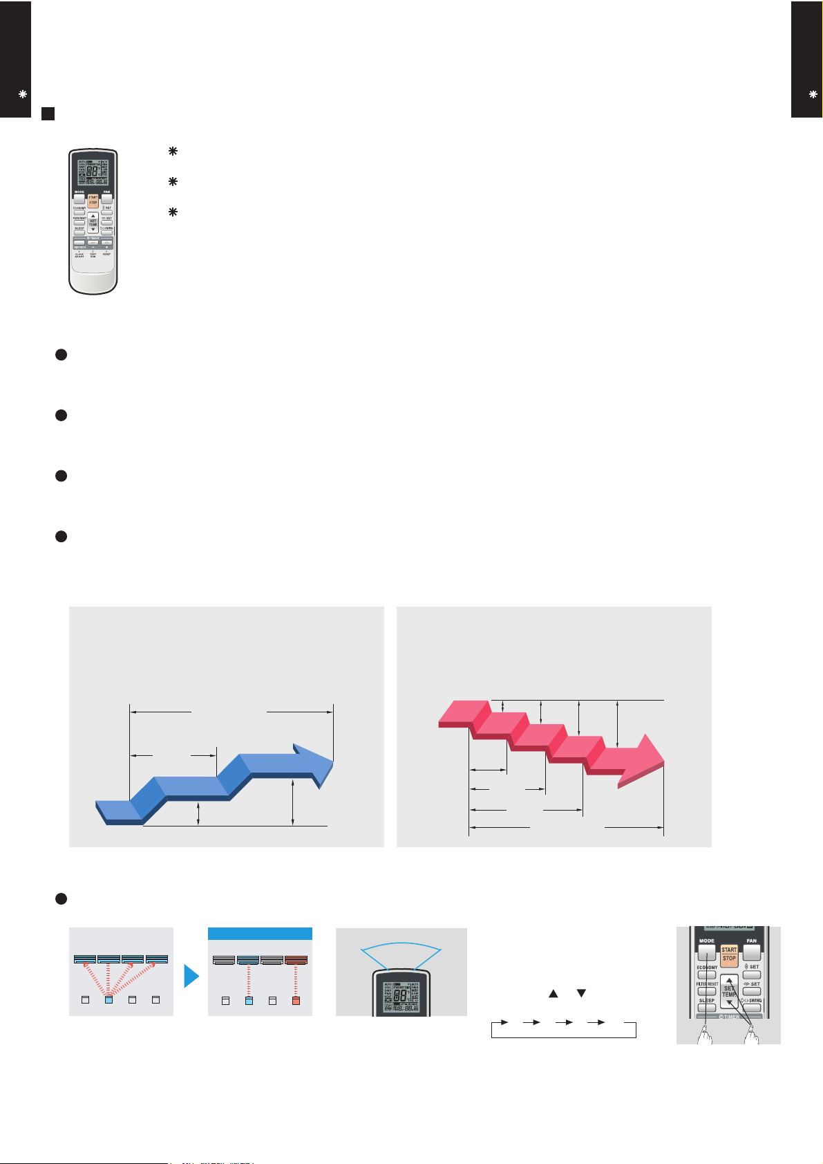
Four kinds of timer setup (ON / OFF / PROGRAM / SLEEP) are possible.
Four kinds of timers. Easy operation.
Easy to change transmission code (4 patterns) by button operation.
Simple function setting
Setting of the air conditioner selection function is performed by remote controller.
Built-in timers
Select from four different timer programs (On/Off/Program/Sleep).
CASSETTE TYPE
AU A18-24L
Program timer
The program timer operates the ON and OFF timer once within a 24 hour period.
Sleep timer
The sleep timer function automatically corrects the temperature thermostat setting according to the
time setting to prevent excessive cooling and heating while sleeping.
Cooling operation/dry operation
When the sleep timer is set, the set temperature
automatically rises 1 °C every hour. The set
temperature can rise up to a maximum of 2 °C.
Timer setting
60min.
1 °C
2 °C
Heating operation
When the sleep timer is set, the set temperature
automatically drops 1 °C every 30 minutes. The
set temperature can drop to a maximum of 4 °C.
1 °C
2 °C
3 °C
4 °C
30min.
60min.
90min.
Timer setting
Simultaneously operation
After code change
Mixed-up
• Code selector switch eliminates unit
being wrongly switched.
(Up to 4 codes can be set.)
A B C D
A B
C
1. Press the MODE button for
more than five seconds
to start the code change.
D
•Wide and precise
transmitting range.
- (01 - 03) -
2. Press the or button to
select the desired code.
A B C D
3. Press the MODE button
again to end the code change.
Page 5
CASSETTE TYPE
AU A18-24L
FUNCTIONS
1
3
2
4
5
11
13
16
10
14
12
15
CASSETTE TYPE
1
MODE button
Selects the operating mode (AUTO, HEAT, FAN, COOL, DRY).
/Start / end R.C. custom code change. (Max 4 types)
2
Economy button
3
Set temp. button ( / )
AU A18-24L
Set remote controller custom code buttons
Sets the indoor temp./ Sets R.C. custom code.
4
Filter reset button
5
Sleep button
Pressed to select sleep timer.
6
6
7
8
9
Fan button
Selects the fan speed (AUTO, QUIET, LOW, MED, HIGH).
7
START/STOP button
Pressed to start and stop operation.
8
Set button (Vertical)
Air flow direction vertical set button.
9
Set button (Horizontal)*
Air flow direction horizontal set button.
10
Swing button
Air flow direction swing button.
11
Timer mode button
Pressed to select the timer mode. (OFF TIMER, ON TIMER,
PROGRAM TIMER, TIMER RESET)
Display panel
17
18
19
20
21
22
23
24
25
12
Timer set ( / ) button
Sets the current time and on-off time.
13
Clock adjust button
Sets the current time.
14
Reset button
Used when replacing batteries.
15
Test run button
Used when testing the air conditioner after installation.
16
Signal transmitter
17
Temperature set display
18
Economy display
19
Operating mode display
20
Sleep display
21
Transmit indicator
22
Fan speed display
23
Swing display
24
Timer mode display
25
Clock display
* These functions are not available.
SPECIFICATION
SIZE (H x W x D mm) 170 x 56 x 19
WEIGHT ( g ) 85 (w/o batteries)
ACCESSORY Holder
- (01 - 04) -
Page 6
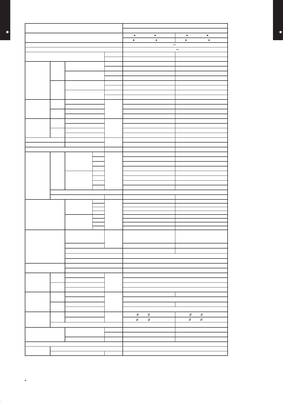
3. SPECIFICATIONS
CASSETTE TYPE
AU A18-24L
Type
Model name
Power source
Available voltage range
European energy label
Cooling
Capacity
Heating
Input power
Current
EER 3.21 3.21
COP 3.61 3.61
Moisture removal
Fan
Sound pressure level
Heat exchanger type
Enclosure
Dimensions
( H×W×D)
Weight
Connection pipe
Operation range
Remote controller type
Drain pipe
Note :
Specifications are based on the following conditions.
Cooling : Indoor temperature of 27°CDB/19°CWB. and outdoor temperature of 35°CDB/24°CWB.
Heating : Indoor temperature of 20°CDB/15°CWB. and outdoor temperature of 7°CDB/6°CWB.
Pipe length : 7.5 m, Height difference : 0 m. (Outdoor unit - Indoor unit)
Ceiling mode : Standard
The maximum current and the maximum input value are the maximum value when operated within the operation range (temperature).
Cooling
Heating
Cooling
Heating
Airflow
rate
Type × Q'ty
Motor output W 54 54
Net
Gross
Net
Gross
Size mm
Method Flare Flare
Material
Size
Rated
Min.-Max.
Rated
Min.-Max.
Rated
*Max.
Rated
*Max.
Rated
*Max.
Rated
*Max.
Cooling
Heating
Cooling
Heating
Cooling
Heating
Dimensions (H × W × D)
Fin pitch 1.20 1.45
Rows x Stages 2 x 10 3 x 10
Pipe type
Fin type
Material
Colour
Unit
Panel
Unit
Panel
Unit 15 (33) 17 (37)
Panel
Unit 18 (40) 20 (44)
Panel
Liquid 6.35 ( 1/4 in.)
Gas 12.70( 1/2 in.) 15.88( 5/8 in.)
Cooling
Heating °C 30 or less 30 or less
Cooling A A
Heating A A
kW 5.20 7.10
BTU/h 17700 24200
kW 0.90 - 5.90 0.90 - 8.00
BTU/h 3100 - 20100 3100 - 27300
kW 6.00 8.00
BTU/h 20500 27300
kW 0.90 - 7.50 0.90 - 9.10
BTU/h 3100 - 25600 3100 - 31000
kW
A
kW/kW
l/h (pints/h) 2.2 ( 3.9 ) 2.7 ( 4.8 )
High 680 930
Med 580 830
Low 490 600
Quiet 410 450
High 800 930
Med 680 860
Low 580 700
Quiet 450 530
High 38 49
Med 34 44
Low 30 36
Quiet 26 30
High 43 49
Med 38 45
Low 34 40
Quiet 30 33
m3/h
dB(A)
mm
mm
kg(lb.)
°C 18 to 32 18 to 32
%RH 80 or less 80 or less
mm
AU A18LAL, AU F18LAL AU A24LAL, AU A24LBL
AO A18LACL, AO A18LALL
1.62 2.21
2.16 2.85
1.66 2.21
2.96 3.19
7.1 9.7
9.0 12.0
7.3 9.7
12.5 13.5
210 × 1310 × 13.3
210 × 1250 × 13.3
6.35 ( 1/4 in.)
Outer diameter : 25.4 / Inner diameter : 19.4
CASSETTE MODEL
INVERTER HEATPUMP
AO A24LACL, AO A24LALL
230V 50Hz
198-264V 50Hz
Turbo × 1
210 × 1375 × 13.3
210 × 1310 × 13.3
210 × 1250 × 13.3
Copper tube
Aluminium
PS
WHITE
245 × 570 × 570
49 x 700 x 700
265 x 730 x 625
120 x 765 x 755
2.6 (5.7)
4.5 (10.0)
WIRELESS
ABS
CASSETTE TYPE
AU A18-24L
- (01 - 05) -
Page 7
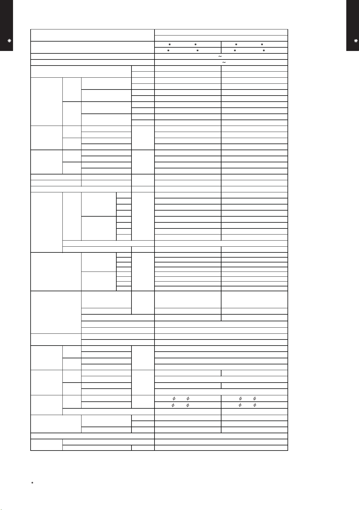
CASSETTE TYPE
AU A18-24L
Type
Model name
Power source 230V 50Hz
Available voltage range 198-264V 50Hz
European energy label
Cooling
Capacity
Heating
Input power
Current
EER 3.06 3.06
COP 3.43 3.43
Moisture removal
Fan
Sound pressure level
Heat exchanger type
Enclosure
Dimensions
( H×W×D)
Weight
Connection pipe
Operation range
Remote controller type WIRELESS
Drain pipe
Note :
Specifications are based on the following conditions.
Cooling : Indoor temperature of 27°CDB/19°CWB. and outdoor temperature of 35°CDB/24°CWB.
Heating : Indoor temperature of 20°CDB/15°CWB. and outdoor temperature of 7°CDB/6°CWB.
Pipe length : 7.5 m, Height difference : 0 m. (Outdoor unit - Indoor unit)
Ceiling mode : Standard
The maximum current and the maximum input value are the maximum value when operated within the operation range (temperature).
Cooling
Heating
Cooling
Heating
Airflow
rate
Type × Q'ty
Motor output W 54 54
Net
Gross
Net
Gross
Size mm
Method Flare Flare
Material ABS
Size Outer diameter : 25.4 / Inner diameter : 19.4
Rated
Min.-Max.
Rated
Min.-Max.
Rated
*Max.
Rated
*Max.
Rated
*Max.
Rated
*Max.
Cooling
Heating
Cooling
Heating
Cooling
Heating
Dimensions (H × W × D)
Fin pitch 1.20 1.45
Rows x Stages 2X10 3X10
Pipe type
Fin type
Material
Colour
Unit
Panel
Unit
Panel
Unit 15 (33) 17 (37)
Panel
Unit 18 (40) 20 (44)
Panel
Liquid 6.35 ( 1/4 in.) 6.35 ( 1/4 in.)
Gas 12.70( 1/2 in.) 15.88( 5/8 in.)
Cooling
Heating °C 30 or less 30 or less
Cooling B B
Heating B B
kW 5.20 7.10
BTU/h 17700 24200
kW 0.90 - 5.70 0.90 - 7.80
BTU/h 3100 - 19500 3100 - 26600
kW 6.00 8.00
BTU/h 20500 27300
kW 0.90 - 7.20 0.90 - 8.80
BTU/h 3100 - 24600 3100 - 30000
kW
A
kW/kW
l/h (pints/h) 2.2 ( 3.9 ) 2.7 ( 4.8 )
High 680 930
Med 580 830
Low 490 600
Quiet 410 450
High 800 930
Med 680 860
Low 580 700
Quiet 450 530
High 38 49
Med 34 44
Low 30 36
Quiet 26 30
High 43 49
Med 38 45
Low 34 40
Quiet 30 33
m3/h
dB(A)
mm
mm
kg(lb.)
°C 18 to 32 18 to 32
%RH 80 or less 80 or less
mm
AU A18LAL, AU F18LAL AU A24LAL, AU A24LBL
AO B18LACL, AO B18LALL AO B24LACL, AO B24LALL
1.70 2.32
2.16 2.85
1.75 2.33
2.96 3.19
7.4 10.1
9.0 12.0
7.7 10.2
12.5 13.5
210 × 1310 × 13.3
210 × 1250 × 13.3
CASSETTE MODEL
INVERTER HEATPUMP
Turbo × 1
210 × 1375 × 13.3
210 × 1310 × 13.3
210 × 1250 × 13.3
Copper tube
Aluminium
PS
WHITE
245 x 570 x 570
49 x 700 x 700
265 x 730 x 625
120 x 765 x 755
2.6 (5.7)
4.5 (10.0)
CASSETTE TYPE
AU A18-24L
- (01 - 06) -
Page 8
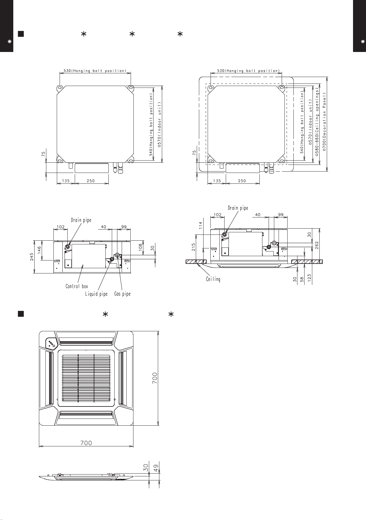
4. DIMENSIONS
MODEL : AU A18L, AU F18L, AU A24L
CASSETTE TYPE
AU A18-24L
Top view
•
Decoration panel mounting state
(Unit : mm)
CASSETTE TYPE
AU A18-24L
Side view
MODEL : UTG-UF A-W, UTG-UF B-W
Bottom view
Side view
- (01 - 07) -
Page 9
Floor
CASSETTE TYPE
AU A18-24L
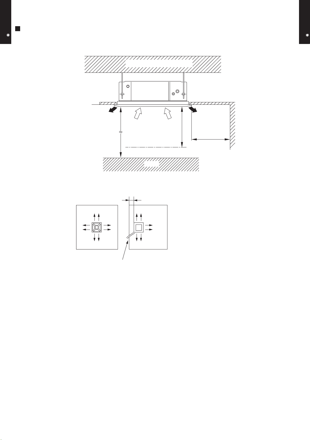
MOUNTING POSITION
Strong and durable ceiling
(Unit : mm)
CASSETTE TYPE
AU A18-24L
Ceiling mode “Standard” : 2,500 - 3,000
Ceiling mode “High” : 3,000 - 3,500
(4 directions) (3 directions)
Piping position
Obstruction
100 or more
1,200
or more
1,000
or more
- (01 - 08) -
Page 10
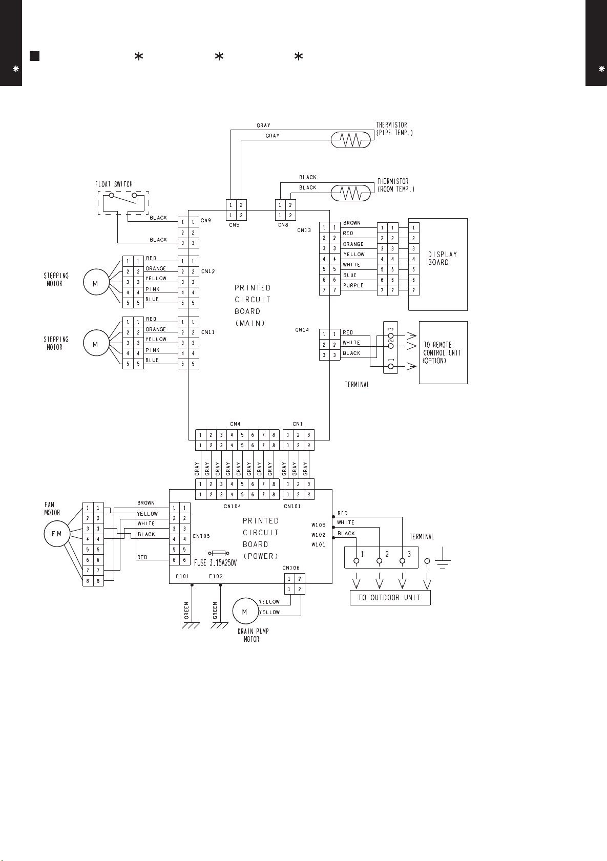
5. WIRING DIAGRAMS
MODEL : AU A18L, AU F18L, AU A24L
CASSETTE TYPE
AU A18-24L
CASSETTE TYPE
AU A18-24L
- (01 - 09) -
Page 11
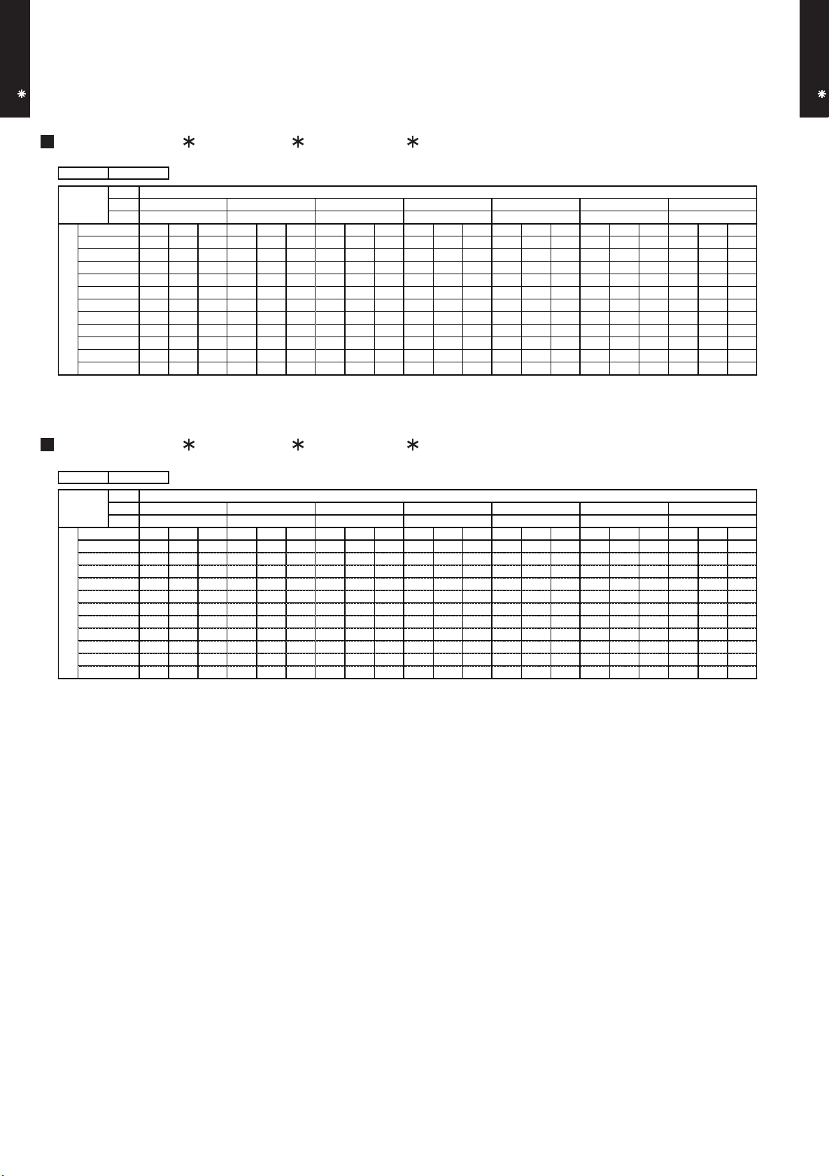
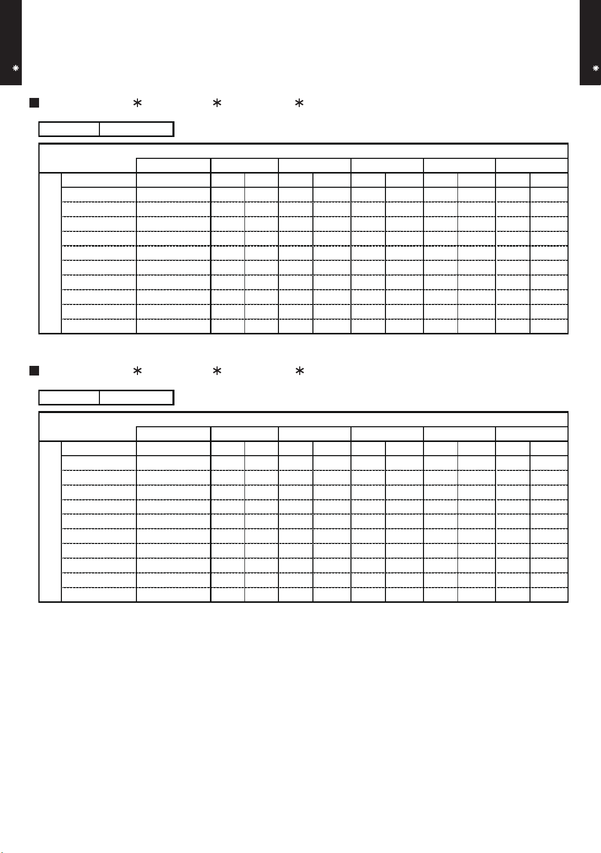
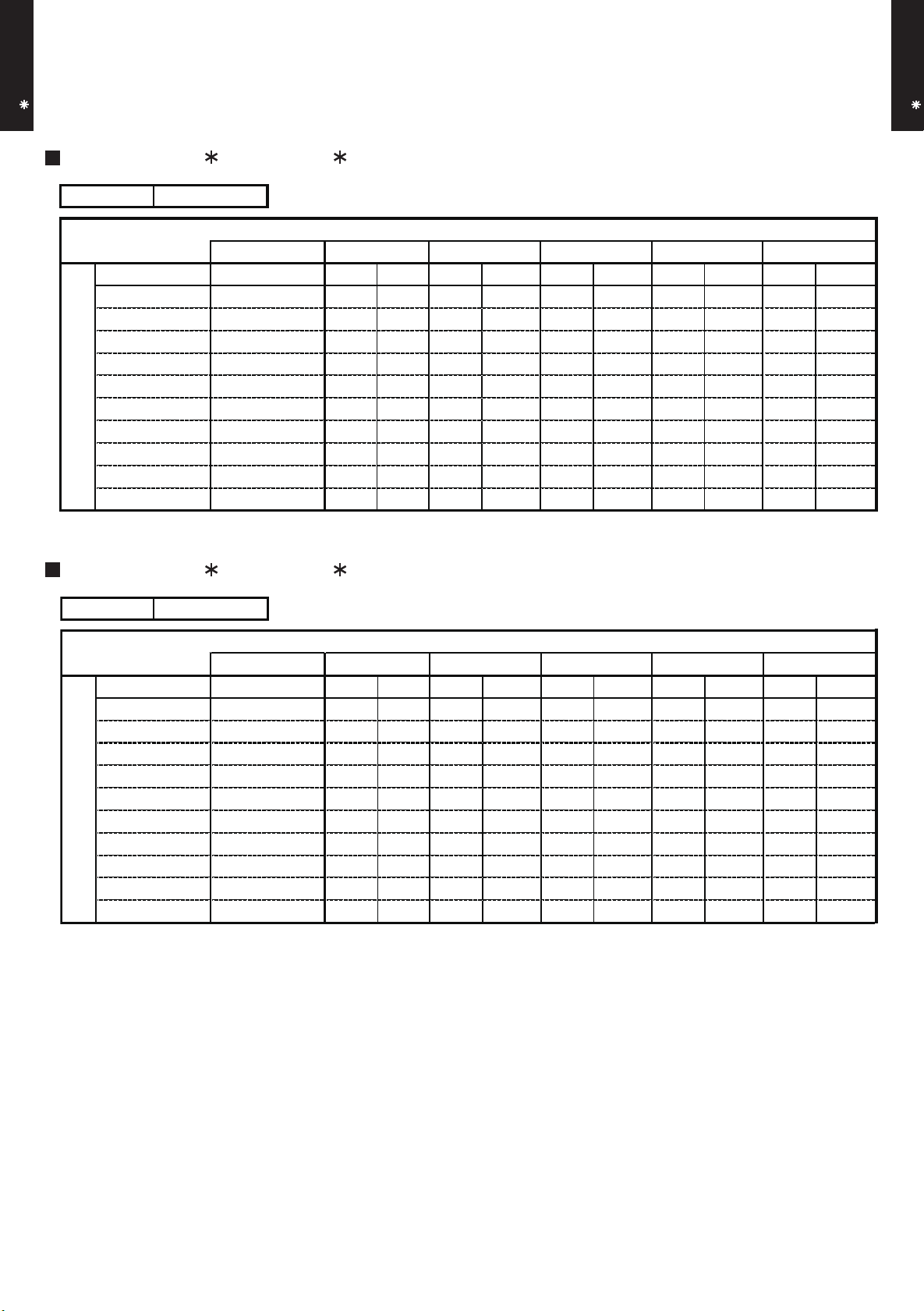
6. CAPACITY TABLE
°CDB
°CWB
TC SHC PI TC SHC PI TC SHC PI TC SHC PI TC SHC PI TC SHC PI TC SHC PI
4.45 3.38 0.44 4.96 3.40 0.44 5.13 3.69 0.44 5.47 3.71 0.45 5.64 4.00 0.45 5.97 3.99 0.46 6.31 4.25 0.46
4.35 3.32 0.51 4.85 3.34 0.52 5.01 3.64 0.52 5.34 3.65 0.52 5.51 3.94 0.53 5.84 3.92 0.53 6.17 4.18 0.54
4.23 3.26 0.63 4.71 3.28 0.64 4.87 3.57 0.64 5.19 3.58 0.65 5.35 3.86 0.65 5.67 3.85 0.66 6.00 4.10 0.66
4.09 3.19 0.74 4.56 3.21 0.75 4.71 3.49 0.76 5.02 3.50 0.76 5.18 3.78 0.77 5.49 3.76 0.78 5.80 4.01 0.78
4.10 3.20 0.65 4.57 3.21 0.66 4.72 3.49 0.66 5.04 3.51 0.67 5.19 3.79 0.67 5.50 3.77 0.68 5.82 4.02 0.69
5.16 3.75 1.37 5.74 3.77 1.39 5.94 4.10 1.40 6.33 4.12 1.41 6.53 4.44 1.42 6.92 4.43 1.44 7.31 4.72 1.45
4.94 3.64 1.53 5.51 3.66 1.56 5.70 3.98 1.56 6.07 3.99 1.58 6.26 4.31 1.59 6.63 4.29 1.60 7.01 4.57 1.62
4.72 3.52 1.69 5.26 3.54 1.72 5.44 3.85 1.73 5.79 3.86 1.75 5.97 4.17 1.75 6.33 4.15 1.77 6.69 4.42 1.79
4.66 3.49 2.00 5.19 3.51 2.03 5.37 3.81 2.04 5.72 3.83 2.06 5.90 4.13 2.07 6.25 4.11 2.09 6.61 4.38 2.11
3.59 2.94 1.43 4.00 2.95 1.45 4.13 3.21 1.46 4.40 3.22 1.47 4.54 3.48 1.48 4.81 3.47 1.49 5.09 3.69 1.51
2.58 2.45 1.08 2.87 2.46 1.10 2.97 2.68 1.10 3.17 2.69 1.11 3.27 2.90 1.12 3.46 2.89 1.13 3.66 3.08 1.14
0
5
AFR
11.3
°CDB
-10
Outdoor temperature
40
46
35
Indoor temperature
18212325272932
21231215161819
10
30
25
20
15
°CDB
°CWB
TC SHC PI TC SHC PI TC SHC PI TC SHC PI TC SHC PI TC SHC PI TC SHC PI
4.45 3.38 0.44 4.96 3.40 0.44 5.13 3.69 0.44 5.47 3.71 0.45 5.64 4.00 0.45 5.97 3.99 0.46 6.31 4.25 0.46
4.35 3.32 0.51 4.85 3.34 0.52 5.01 3.64 0.52 5.34 3.65 0.52 5.51 3.94 0.53 5.84 3.92 0.53 6.17 4.18 0.54
4.23 3.26 0.63 4.71 3.28 0.64 4.87 3.57 0.64 5.19 3.58 0.65 5.35 3.86 0.65 5.67 3.85 0.66 6.00 4.10 0.66
4.09 3.19 0.74 4.56 3.21 0.75 4.71 3.49 0.76 5.02 3.50 0.76 5.18 3.78 0.77 5.49 3.76 0.78 5.80 4.01 0.78
4.10 3.20 0.65 4.57 3.21 0.66 4.72 3.49 0.66 5.04 3.51 0.67 5.19 3.79 0.67 5.50 3.77 0.68 5.82 4.02 0.69
5.16 3.75 1.37 5.74 3.77 1.39 5.94 4.10 1.40 6.33 4.12 1.41 6.53 4.44 1.42 6.92 4.43 1.44 7.31 4.72 1.45
4.94 3.64 1.53 5.51 3.66 1.56 5.70 3.98 1.56 6.07 3.99 1.58 6.26 4.31 1.59 6.63 4.29 1.60 7.01 4.57 1.62
4.72 3.52 1.69 5.26 3.54 1.72 5.44 3.85 1.73 5.79 3.86 1.75 5.97 4.17 1.75 6.33 4.15 1.77 6.69 4.42 1.79
4.50 3.32 2.00 5.02 3.34 2.03 5.19 3.63 2.04 5.53 3.64 2.06 5.70 3.93 2.07 6.04 3.91 2.09 6.38 4.17 2.11
3.47 2.81 1.43 3.86 2.82 1.45 3.99 3.07 1.46 4.26 3.08 1.47 4.39 3.33 1.48 4.65 3.31 1.49 4.91 3.53 1.51
2.49 2.36 1.08 2.78 2.37 1.10 2.87 2.58 1.10 3.06 2.59 1.11 3.16 2.79 1.12 3.34 2.78 1.13 3.53 2.96 1.14
46
25
30
35
40
10
15
AFR
11.3
Indoor temperature
18
21
Outdoor temperature
12
15
°CDB
-10
0
5
20
32
2319211618
272923
25
6-1. COOLING CAPACITY
CASSETTE TYPE
AU A18-24L
This table is created using the maximum capacity.
MODEL : AU A18L, AU F18L / AO A18L
MODEL : AU A18L, AU F18L / AO B18L
CASSETTE TYPE
AU A18-24L
AFR : Air Flow Rate (m3/min)
TC : Total Capacity (kW)
SHC : Sensible Heat Capacity (kW)
PI : Power Input (kW)
- (01 - 10) -
Page 12
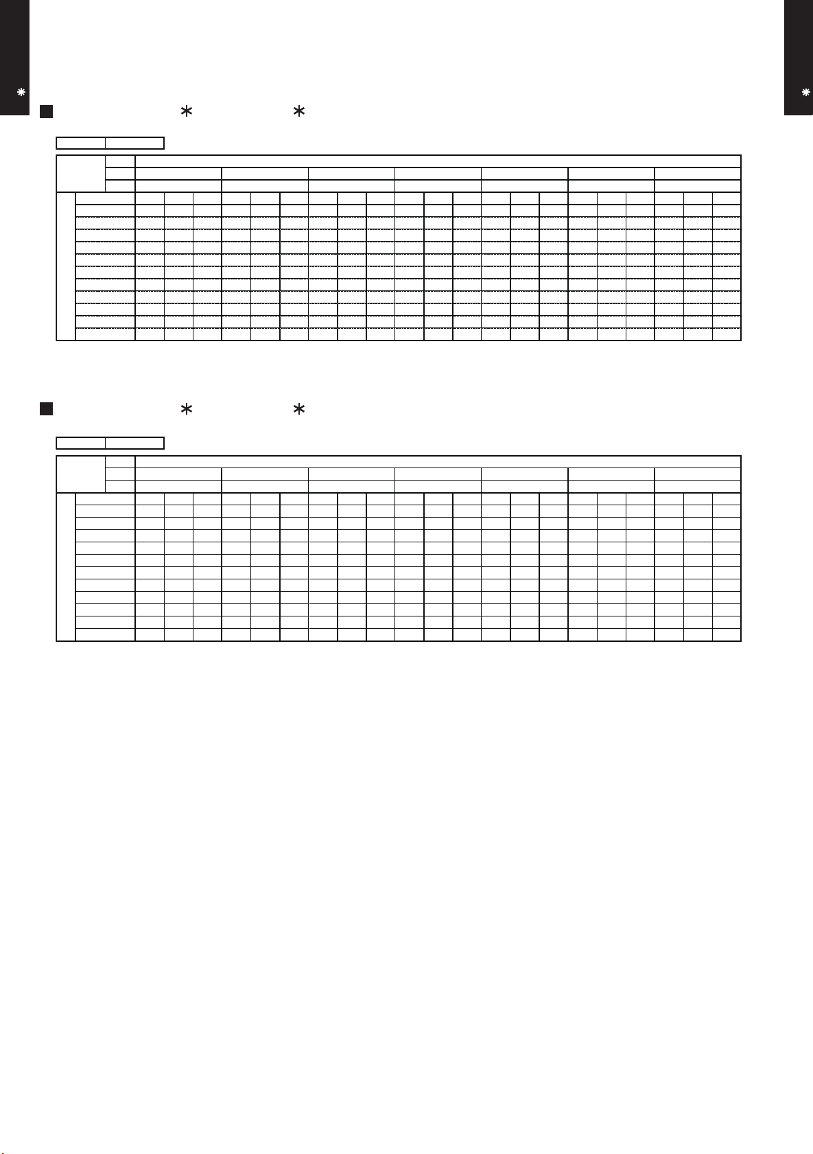
CASSETTE TYPE
°CDB
°CWB
TC SHC PI TC SHC PI TC SHC PI TC SHC PI TC SHC PI TC SHC PI TC SHC PI
5.62 4.52 0.60 6.26 4.54 0.60 6.47 4.94 0.61 6.90 4.95 0.61 7.11 5.35 0.62 7.54 5.33 0.62 7.96 5.68 0.63
5.52 4.47 0.64 6.15 4.49 0.65 6.36 4.89 0.66 6.78 4.90 0.66 6.99 5.29 0.67 7.41 5.27 0.67 7.83 5.62 0.68
5.33 4.37 0.78 5.94 4.40 0.79 6.14 4.78 0.80 6.55 4.80 0.80 6.75 5.18 0.81 7.15 5.16 0.82 7.56 5.50 0.82
5.12 4.26 0.91 5.71 4.29 0.92 5.90 4.66 0.93 6.29 4.68 0.94 6.49 5.05 0.94 6.87 5.03 0.95 7.26 5.36 0.96
5.25 4.33 0.76 5.85 4.35 0.77 6.05 4.73 0.78 6.45 4.75 0.79 6.65 5.13 0.79 7.05 5.11 0.80 7.44 5.44 0.81
6.75 5.11 1.65 7.52 5.15 1.67 7.77 5.59 1.68 8.29 5.61 1.70 8.54 6.06 1.71 9.05 6.04 1.73 9.57 6.43 1.74
6.41 4.93 1.78 7.14 4.96 1.81 7.38 5.39 1.82 7.87 5.41 1.84 8.11 5.84 1.85 8.60 5.82 1.86 9.08 6.20 1.88
6.07 4.75 1.98 6.76 4.78 2.01 6.99 5.20 2.02 7.46 5.22 2.04 7.69 5.63 2.05 8.15 5.61 2.07 8.61 5.98 2.09
6.32 4.88 2.52 7.04 4.91 2.56 7.28 5.34 2.57 7.76 5.36 2.60 8.00 5.79 2.61 8.48 5.76 2.64 8.96 6.14 2.66
5.22 4.31 2.10 5.81 4.34 2.14 6.01 4.72 2.15 6.41 4.73 2.17 6.61 5.11 2.18 7.00 5.09 2.20 7.40 5.42 2.22
3.74 3.58 1.59 4.17 3.60 1.61 4.31 3.91 1.62 4.60 3.92 1.64 4.74 4.24 1.65 5.02 4.22 1.66 5.31 4.50 1.68
30
35
40
Outdoor temperature
°CDB
-10
0
5
10
15
20
46
25
19212312151618
AFR
15.5
Indoor temperature
18212325272932
°CDB
°CWB
TC SHC PI TC SHC PI TC SHC PI TC SHC PI TC SHC PI TC SHC PI TC SHC PI
5.62 4.52 0.60 6.26 4.54 0.60 6.47 4.94 0.61 6.90 4.95 0.61 7.11 5.35 0.62 7.54 5.33 0.62 7.96 5.68 0.63
5.52 4.47 0.64 6.15 4.49 0.65 6.36 4.89 0.66 6.78 4.90 0.66 6.99 5.29 0.67 7.41 5.27 0.67 7.83 5.62 0.68
5.33 4.37 0.78 5.94 4.40 0.79 6.14 4.78 0.80 6.55 4.80 0.80 6.75 5.18 0.81 7.15 5.16 0.82 7.56 5.50 0.82
5.12 4.26 0.91 5.71 4.29 0.92 5.90 4.66 0.93 6.29 4.68 0.94 6.49 5.05 0.94 6.87 5.03 0.95 7.26 5.36 0.96
5.25 4.33 0.76 5.85 4.35 0.77 6.05 4.73 0.78 6.45 4.75 0.79 6.65 5.13 0.79 7.05 5.11 0.80 7.44 5.44 0.81
6.75 5.11 1.65 7.52 5.15 1.67 7.77 5.59 1.68 8.29 5.61 1.70 8.54 6.06 1.71 9.05 6.04 1.73 9.57 6.43 1.74
6.41 4.93 1.78 7.14 4.96 1.81 7.38 5.39 1.82 7.87 5.41 1.84 8.11 5.84 1.85 8.60 5.82 1.86 9.08 6.20 1.88
6.07 4.75 1.98 6.76 4.78 2.01 6.99 5.20 2.02 7.46 5.22 2.04 7.69 5.63 2.05 8.15 5.61 2.07 8.61 5.98 2.09
6.16 4.72 2.52 6.86 4.74 2.56 7.10 5.16 2.57 7.57 5.17 2.60 7.80 5.59 2.61 8.27 5.57 2.64 8.74 5.93 2.66
5.09 4.17 2.10 5.67 4.20 2.14 5.86 4.56 2.15 6.25 4.58 2.17 6.44 4.94 2.18 6.83 4.92 2.20 7.22 5.25 2.22
3.65 3.48 1.59 4.06 3.50 1.61 4.20 3.80 1.62 4.48 3.81 1.64 4.62 4.12 1.65 4.90 4.10 1.66 5.17 4.37 1.68
AFR
15.5
46
25
30
35
40
Indoor temperature
Outdoor temperature
12
18
21
5
20
10
15
15
°CDB
-10
0
16
18
2729232532
231921
AU A18-24L
MODEL : AU A24L / AO A24L
MODEL : AU A24L / AO B24L
CASSETTE TYPE
AU A18-24L
AFR : Air Flow Rate (m3/min)
TC : Total Capacity (kW)
SHC : Sensible Heat Capacity (kW)
PI : Power Input (kW)
- (01 - 11) -
Page 13
6-2. HEATING CAPACITY
TC PI TC PI TC PI TC PI TC PI
5.01 2.50 4.89 2.55 4.77 2.60 4.65 2.65 4.53 2.71
5.76 2.61 5.62 2.67 5.49 2.72 5.35 2.77 5.21 2.83
6.49 2.73 6.34 2.79 6.18 2.85 6.03 2.90 5.87 2.96
7.35 2.80 7.18 2.86 7.00 2.92 6.83 2.98 6.65 3.04
8.04 2.79 7.85 2.84 7.66 2.90 7.47 2.96 7.28 3.02
7.87 2.42 7.69 2.47 7.50 2.52 7.31 2.57 7.12 2.62
8.12 2.43 7.92 2.48 7.73 2.53 7.54 2.58 7.34 2.63
7.79 2.13 7.61 2.17 7.42 2.22 7.23 2.26 7.05 2.31
7.17 1.64 7.00 1.67 6.83 1.71 6.66 1.74 6.49 1.77
7.39 1.65 7.21 1.68 7.03 1.71 6.86 1.75 6.68 1.78
182022
24
AFR
13.3
°CDB
16
Outdoor temperature
°CDB
°CWB
-15
-16
-10
-11
-5
10
8
-7
0
-2
5
3
24
18
Indoor temperature
15
10
20
15
7
6
TC PI TC PI TC PI TC PI TC PI
5.01 2.50 4.89 2.55 4.77 2.60 4.65 2.65 4.53 2.71
5.76 2.61 5.62 2.67 5.49 2.72 5.35 2.77 5.21 2.83
6.49 2.73 6.34 2.79 6.18 2.85 6.03 2.90 5.87 2.96
7.06 2.80 6.89 2.86 6.72 2.92 6.55 2.98 6.38 3.04
7.72 2.79 7.54 2.84 7.35 2.90 7.17 2.96 6.99 3.02
7.56 2.42 7.38 2.47 7.20 2.52 7.02 2.57 6.84 2.62
7.79 2.43 7.61 2.48 7.42 2.53 7.23 2.58 7.05 2.63
7.48 2.13 7.30 2.17 7.12 2.22 6.94 2.26 6.77 2.31
6.89 1.64 6.72 1.67 6.56 1.71 6.39 1.74 6.23 1.77
7.09 1.65 6.92 1.68 6.75 1.71 6.58 1.75 6.42 1.78
182022
10
°CDB
°CWB
-15
24
-10
-5
16
AFR
°CDB
13.3
Outdoor temperature
0
-2
151820
7
24
-16
-11
-7
8
563
10
15
Indoor temperature
CASSETTE TYPE
AU A18-24L
This table is created using the maximum capacity.
MODEL : AU A18L, AU F18L / AO A18L
CASSETTE TYPE
AU A18-24L
MODEL : AU A18L, AU F18L / AO B18L
AFR: Air Flow Rate (m3/min)
TC : Total Capacity (kW)
PI : Power Input (kW)
- (01 - 12) -
Page 14
CASSETTE TYPE
TC PI TC PI TC PI TC PI TC PI
6.15 2.84 6.01 2.90 5.86 2.96 5.72 3.01 5.57 3.07
6.92 3.03 6.75 3.09 6.59 3.15 6.42 3.22 6.26 3.28
7.64 3.02 7.45 3.08 7.27 3.14 7.09 3.20 6.91 3.27
8.59 3.00 8.38 3.06 8.18 3.12 7.97 3.18 7.77 3.25
9.54 3.02 9.31 3.08 9.09 3.14 8.86 3.20 8.63 3.27
9.55 2.69 9.33 2.74 9.10 2.80 8.87 2.86 8.64 2.91
9.87 2.69 9.63 2.75 9.40 2.80 9.16 2.86 8.93 2.92
8.97 2.07 8.76 2.12 8.54 2.16 8.33 2.20 8.11 2.25
8.23 1.63 8.03 1.66 7.84 1.69 7.64 1.73 7.45 1.76
8.52 1.62 8.32 1.66 8.12 1.69 7.92 1.73 7.71 1.76
AFR
15.5
°CDB
16
Outdoor temperature
°CDB
°CWB
3
7
6
10
182022
24
Indoor temperature
24
18
8
15
10
20
0
-2
15
-15
-5
-7
5
-16
-10
-11
TC PI TC PI TC PI TC PI TC PI
6.15 2.84 6.01 2.90 5.86 2.96 5.72 3.01 5.57 3.07
6.69 3.03 6.53 3.09 6.37 3.15 6.21 3.22 6.05 3.28
7.38 3.02 7.21 3.08 7.03 3.14 6.86 3.20 6.68 3.27
8.30 3.00 8.10 3.06 7.91 3.12 7.71 3.18 7.51 3.25
9.23 3.02 9.01 3.08 8.79 3.14 8.57 3.20 8.35 3.27
9.24 2.69 9.02 2.74 8.80 2.80 8.58 2.86 8.36 2.91
9.54 2.69 9.31 2.75 9.09 2.80 8.86 2.86 8.63 2.92
8.67 2.07 8.47 2.12 8.26 2.16 8.05 2.20 7.85 2.25
7.96 1.63 7.77 1.66 7.58 1.69 7.39 1.73 7.20 1.76
8.24 1.62 8.05 1.66 7.85 1.69 7.65 1.73 7.46 1.76
182022
10
°CDB
°CWB
-15
24
-10
-5
16
AFR
°CDB
15.5
Outdoor temperature
0
-2
151820
7
24
-16
-11
-7
8
563
10
15
Indoor temperature
AU A18-24L
MODEL : AU A24L / AO A24L
MODEL : AU A24L / AO B24L
CASSETTE TYPE
AU A18-24L
AFR: Air Flow Rate (m3/min)
TC : Total Capacity (kW)
PI : Power Input (kW)
- (01 - 13) -
Page 15
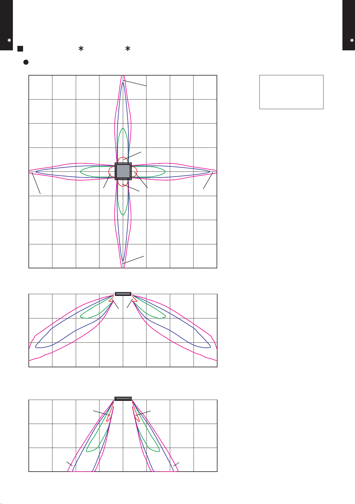
7. FAN PERFORMANCE
7-1. AIR VELOCITY DISTRIBUTION
CASSETTE TYPE
AU A18-24L
MODEL : AU A18L, AU F18L
4-WAY AIR OUTLET
(m)
4
0.25
3
Unit : m/s
Note :
Condition
Fan speed : High
Operation mode : FAN
Ceiling mode : Standard
CASSETTE TYPE
AU A18-24L
2
1
0
1
0.25
0.5
1
2
0.5
1
2
1
2
1
0.5
2
2
0.5
0.25
3
0.25
4
4 3 2 1 0 1 2 3 4
(m)
3
Unit : m/s
TOP VIEW
HORIZONTAL LOUVER
: Upward
(m)
2
1
2
1
2
0.5
0.5
1
0.25
0
4 3 2 1 0 1 2 3 4
(m)
3
2
2
Unit : m/s
2
1
1
1
0.25
0.5
0.5
0.25
0
4 3 2 1 0 1 2 3 4
0.25
SIDE VIEW
HORIZONTAL LOUVER
: Upward
(m)
SIDE VIEW
HORIZONTAL LOUVER
: Downward
(m)
- (01 - 14) -
Page 16
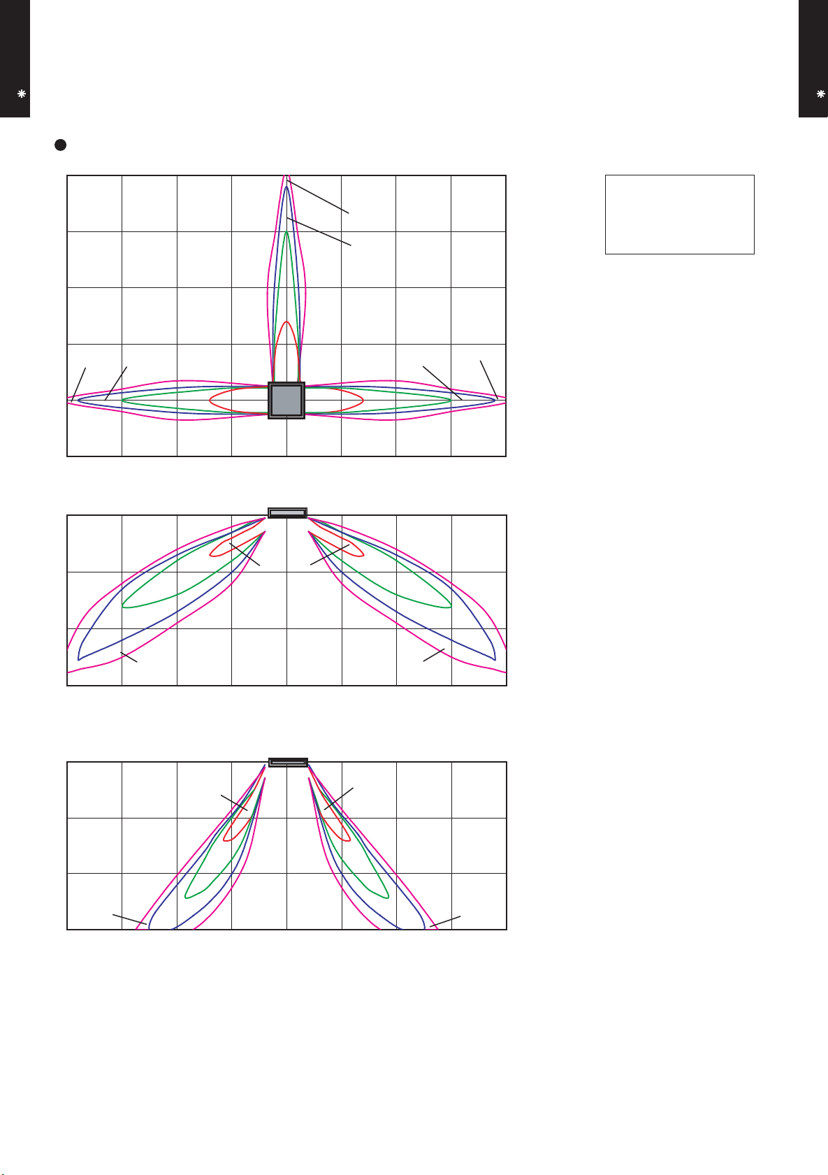
CASSETTE TYPE
AU A18-24L
3-WAY AIR OUTLET
(m)
4
3
0.25
0.5
Unit : m/s
Note :
Condition
Fan speed : High
Operation mode : FAN
Ceiling mode : Standard
CASSETTE TYPE
AU A18-24L
2
1
0.25
0
0.5
1 2
1
2
2
0.5
1
0.25
4 3 2 1 0 1 2 3 4
(m)
3
2
1
0.5
1
0.25
2 2
Unit : m/s
1
0.5
0.25
0
4 3 2 1 0 1 2 3 4
TOP VIEW
HORIZONTAL LOUVER
: Upward
(m)
SIDE VIEW
HORIZONTAL LOUVER
: Upward
(m)
(m)
3
2
2
Unit : m/s
2
1
1
0.25
0.5
1
0.5
0.25
0
4 3 2 1 0 1 2 3 4
SIDE VIEW
HORIZONTAL LOUVER
: Downward
(m)
- (01 - 15) -
Page 17

CASSETTE TYPE
AU A18-24L
MODEL : AU A24L
4-WAY AIR OUTLET
(m)
4
3
0.25
0.5
Unit : m/s
Note :
Condition
Fan speed : High
Operation mode : FAN
Ceiling mode : Standard
CASSETTE TYPE
AU A18-24L
2
1
0
0.25
0.5
1
1
2
2
2
2
1
0.5
1
2
3
1
0.5
0.25
4
4 3 2 1 0 1 2 3 4
(m)
3
Unit : m/s
0.25
TOP VIEW
HORIZONTAL LOUVER
: Upward
(m)
2
2
0.5
1
2
1
0.5
1
0.25
0.25
0
4 3 2 1 0 1 2 3 4
(m)
3
2
2
Unit : m/s
2
1
1
1
0.25
0.5
0.5
0.25
0
4 3 2 1 0 1 2 3 4
SIDE VIEW
HORIZONTAL LOUVER
: Upward
(m)
SIDE VIEW
HORIZONTAL LOUVER
: Downward
(m)
- (01 - 16) -
Page 18

CASSETTE TYPE
AU A18-24L
3-WAY AIR OUTLET
(m)
4
3
0.25
0.5
Unit : m/s
Note :
Condition
Fan speed : High
Operation mode : FAN
Ceiling mode : Standard
CASSETTE TYPE
AU A18-24L
2
1
1
0.25
0
0.5
1
2
2
2
0.5
1
0.25
4 3 2 1 0 1 2 3 4
(m)
3
2
2
1
2
1
0.5
0.25
Unit : m/s
1
0.5
0.25
0
4 3 2 1 0 1 2 3 4
TOP VIEW
HORIZONTAL LOUVER
: Upward
(m)
SIDE VIEW
HORIZONTAL LOUVER
: Upward
(m)
(m)
3
2
1
0.25
0
0.5
2
1
2
1
0.5
Unit : m/s
0.25
4 3 2 1 0 1 2 3 4
SIDE VIEW
HORIZONTAL LOUVER
: Downward
(m)
- (01 - 17) -
Page 19

7-2. AIR FLOW
HIGH
730
MED
FAN SPEED
NUMBER OF
ROTATIONS
(r.p.m)
AIR FLOW
LOW
QUIET
630
540
460
FAN SPEED
NUMBER OF
ROTATIONS
(r.p.m)
AIR FLOW
HIGH
MED
LOW
QUIET
830
730
630
500
7-2-1. STANDARD CEILING MODE
CASSETTE TYPE
AU A18-24L
MODEL : AU A18L, AU F18L
COOLING
CASSETTE TYPE
AU A18-24L
HEATING
m3/h
l/s 189
CFM 400
m3/h
l/s 161
CFM 341
m3/h
l/s 136
CFM 288
m3/h
l/s 114
CFM 241
680
580
490
410
m3/h
l/s 222
CFM 471
m3/h
l/s 189
CFM 400
m3/h
l/s 161
CFM 341
m3/h
l/s 125
CFM 265
800
680
580
450
- (01 - 18) -
Page 20

CASSETTE TYPE
FAN SPEED
NUMBER OF
ROTATIONS
(r.p.m)
AIR FLOW
HIGH
MED
LOW
QUIET
960
850
650
500
FAN SPEED
NUMBER OF
ROTATIONS
(r.p.m)
AIR FLOW
HIGH
MED
LOW
QUIET
960
880
740
580
AU A18-24L
MODEL : AU A24L
COOLING
CASSETTE TYPE
AU A18-24L
HEATING
m3/h
930
l/s 258
CFM 547
m3/h
830
l/s 231
CFM 488
m3/h
600
l/s 167
CFM 353
m3/h
450
l/s 125
CFM 265
m3/h
930
l/s 258
CFM 547
m3/h
860
l/s 239
CFM 506
m3/h
700
l/s 194
CFM 412
m3/h
530
l/s 147
CFM 312
- (01 - 19) -
Page 21

7-2-2. HIGH CEILING MODE
FAN SPEED
NUMBER OF
ROTATIONS
(r.p.m)
AIR FLOW
HIGH
MED
LOW
QUIET
830
730
640
460
FAN SPEED
NUMBER OF
ROTATIONS
(r.p.m)
AIR FLOW
HIGH
MED
LOW
QUIET
930
830
730
500
CASSETTE TYPE
AU A18-24L
MODEL : AU A18L, AU F18L
COOLING
CASSETTE TYPE
AU A18-24L
HEATING
m3/h
l/s 222
CFM 471
m3/h
l/s 189
CFM 400
m3/h
l/s 164
CFM 347
m3/h
l/s 114
CFM 241
800
680
590
410
m3/h
l/s 250
CFM 530
m3/h
l/s 222
CFM 471
m3/h
l/s 189
CFM 400
m3/h
l/s 125
CFM 265
900
800
680
450
- (01 - 20) -
Page 22

CASSETTE TYPE
FAN SPEED
NUMBER OF
ROTATIONS
(r.p.m)
AIR FLOW
HIGH
1050
MED
950
LOW
QUIET
750
500
FAN SPEED
NUMBER OF
ROTATIONS
(r.p.m)
AIR FLOW
HIGH
1030
MED
LOW
QUIET
980
840
580
AU A18-24L
MODEL : AU A24L
COOLING
CASSETTE TYPE
AU A18-24L
HEATING
m3/h
1030
l/s 286
CFM 606
m3/h
930
l/s 258
CFM 547
m3/h
710
l/s 197
CFM 418
m3/h
450
l/s 125
CFM 265
m3/h
1000
l/s 278
CFM 589
m3/h
960
l/s 267
CFM 565
m3/h
820
l/s 228
CFM 483
m3/h
530
l/s 147
CFM 312
- (01 - 21) -
Page 23

8. OPERATION NOISE
8-1. NOISE LEVEL CURVE
CASSETTE TYPE
AU A18-24L
MODEL : AU A18L, AU F18L
COOLING
80
70
60
50
40
30
QUIET
20
Octave band sound pressure level, dB:(0dB=0.0002µbar)
10
HIGH
NC-65
NC-60
NC-55
NC-50
NC-45
NC-40
NC-35
NC-30
NC-25
NC-20
NC-15
HEATING
80
70
60
50
40
30
QUIET
20
Octave band sound pressure level, dB:(0dB=0.0002µbar)
10
Condition
Ceiling mode : Standard
Air outlet : 4-way air outlet
HIGH
NC-65
NC-60
NC-55
NC-50
NC-45
NC-40
NC-35
NC-30
NC-25
NC-20
NC-15
CASSETTE TYPE
AU A18-24L
0
63 125 250 500 1,000 2,000 4,000 8,000
Octave band center frequency,Hz
MODEL : AU A24L
COOLING
80
70
60
50
HIGH
40
30
QUIET
20
Octave band sound pressure level, dB:(0dB=0.0002µbar)
10
NC-65
NC-60
NC-55
NC-50
NC-45
NC-40
NC-35
NC-30
NC-25
NC-20
NC-15
0
63 125 250 500 1,000 2,000 4,000 8,000
Octave band center frequency,Hz
HEATING
80
70
60
50
HIGH
40
30
20
Octave band sound pressure level, dB:(0dB=0.0002µbar)
10
QUIET
NC-65
NC-60
NC-55
NC-50
NC-45
NC-40
NC-35
NC-30
NC-25
NC-20
NC-15
0
63 125 250 500 1,000 2,000 4,000 8,000
Octave band center frequency,Hz
- (01 - 22) -
0
63 125 250 500 1,000 2,000 4,000 8,000
Octave band center frequency,Hz
Page 24

8-2. SOUND LEVEL CHECK POINT
CASSETTE TYPE
AU A18-24L
Microphone
CASSETTE TYPE
AU A18-24L
Microphone
- (01 - 23) -
Page 25

9. ELECTRIC CHARACTERISTICS
CASSETTE TYPE
AU A18-24L
Model Name
Voltage V
Power Supply
Frequency Hz
Max Operating Current A 0.2 0.3
Circuit breaker A 0.3 0.4
*1)Wiring Spec.
Connection Cable
mm
Limited wiring length m 26 31
*1) Wiring Spec.
Selected Sample
(Selected based on Japan Electrotechnical Standard and Codes Committee E0005)
2
AU A18L
AU F18L
AU A24L
230
50
1.5-2.5 1.5-2.5
CASSETTE TYPE
AU A18-24L
- (01 - 24) -
Page 26

10. SAFETY DEVICE
CASSETTE TYPE
AU A18-24L
Circuit protection Current fuse (PCB)
Protection form
AU A18L
AU F18L
Model
3.15A 250V
AU A24L
CASSETTE TYPE
AU A18-24L
Fan motor protection Thermal protection program
140±20°C OFF
110±20°C ON
- (01 - 25) -
Page 27

11. OPTIONAL PARTS
CASSETTE TYPE
AU A18-24L
Exterior Summary
Parts name
Model No.
CASSETTE TYPE
AU A18-24L
Wired remote
controller
Decoration
panel
Air outlet
shutter plate
UTB- UD
UTG-UF A-F
UTR-YDZA
Unit control is performed by
wired remote controller
For AU A18L, AU A24LA
Ceiling dirt by discharged wind
was made difficult to cling by
reviewing the shape of the
LOUVER.
For AU A18L, AU A24LA
Air outlet shutter plate is installed
at the air outlet when 3-way
direction is performed.
For AU F18L, AU A24LB
Decoration
panel
Air outlet
shutter plate
UTG-UF B-F
UTR-YDZB
Ceiling dirt by discharged wind
was made difficult to cling by
reviewing the shape of the
LOUVER.
For AU F18L, AU A24LB
Air outlet shutter plate is installed
at the air outlet when 3-way
direction is performed.
- (01 - 26) -
Page 28

R410A
OUTDOOR UNIT
2.
SINGLE TYPE :
AO A18LACL
AO A18LALL
AO A24LACL
AO A24LALL
D2D_AO004E/04
2008.04.08
Page 29

1. SPECIFICATIONS
OUTDOOR UNIT
AO A18-24L
Type
Model name
Power source
Available voltage range
Starting current
Airflow
Fan
Sound pressure level
Heat exchanger type
Compressor
Refrigerant
Refrigerant oil
Enclosure
Dimensions
( H × W × D)
Weight kg(lb.)
Connection pipe
rate
Type × Q'ty
Motor output
Type × Q'ty
Motor output
Net
Gross
Net
Gross
Size mm
Method
Max. length
Max. height difference
Cooling
Heating
Cooling
Heating
Dimensions (H × W × D)
Fin pitch
Rows x Stages
Pipe type
Fin type
Type
Charge
Type
Material
Colour
Liquid
Gas
Cooling
Heating
A 7.7 10.0
m3/h
W 54 65
dB(A)
mm
W
g 1250 1700
mm
m
°COperation range
INVERTER HEATPUMP
AO A18LACL AO A24LACL
AO A18LALL AO A24LALL
230V 50Hz
198-264V 50Hz
2000 2470
1910 2470
Propeller × 1
50 52
50 53
546 × 876 × 18.2
546 × 842 × 18.2
1.30 1.40
2 × 26
Copper
Aluminium
Twin Rotary × 1
1100
R410A
POE
Steel sheet
Beige (10YR7.5/1.0NN)
578 × 790 × 300 578 × 790 × 315
648 × 910 × 380
40 (88) 44 (97)
44 (97) 48 (106)
Φ
6.35 (Φ 1/4 in.)
Φ
12.70 (Φ 1/2 in.)
Flare
25(chargeless : 15) 30(chargeless : 15)
15 20
-10 to 46
-15 to 24
546 × 866 × 18.2
546 × 832 × 18.2
504 × 589 × 18.2
2 × 26
1 × 24
Φ
15.88(Φ 5/8 in.)
OUTDOOR UNIT
AO A18-24L
Note :
Specifications are based on the following conditions.
Cooling : Indoor temperature of 27°CDB/19°CWB. and outdoor temperature of 35°CDB/24°CWB.
Heating : Indoor temperature of 20°CDB/15°CWB. and outdoor temperature of 7°CDB/6°CWB.
Pipe length : 7.5 m, Height difference : 0 m. (Outdoor unit - Indoor unit)
- (02 - 01) -
Page 30

2. DIMENSIONS
MODELS : AO A18L, AO A24L
OUTDOOR UNIT
AO A18-24L
Top view
(Unit : mm)
OUTDOOR UNIT
AO A18-24L
Front view
Bottom view
MOUNTING POSITION
When there are obstacles at the
back or front sides.
Air flow
When there are obstacles at the
back, side(s), and top.
AO A18L AO A24L
Side view
When there are obstacles at the
back, side with the installation of
more than one unit.
600 - 1000
100 or more
600 or more
100 - 300
250 or more
(Service space)
300 or more
250 or more
250 or more
If the space is larger that is stated, the condition will be the same as that are no obstacles.
- (02 - 02) -
300 or more
Page 31

3. REFRIGERANT CIRCUIT
OUTDOOR UNIT
AO A18-24L
OUTDOOR UNIT
AO A18-24L
- (02 - 03) -
Page 32

4. WIRING DIAGRAMS
MODELS : AO A18L, AO A24L
OUTDOOR UNIT
AO A18-24L
OUTDOOR UNIT
AO A18-24L
- (02 - 04) -
Page 33

5. CAPACITY COMPENSATION RATE FOR PIPE LENGTH
AND HEIGHT DIFFERENCE
MODEL : AO A18L
OUTDOOR UNIT
AO A18-24L
Height
difference H
(m)
Height
difference H
(m)
COOLING
1
Indoor unit is upper
than outdoor unit.
2
Indoor unit is under
than outdoor unit
HEATING
1
Indoor unit is upper
than outdoor unit.
2
Indoor unit is under
than outdoor unit
Pipe length (m)
5 7.5 10 15 20 25
15 - - -
10 - -
7.5 -
5
0 1.000 1.000 0.999 0.984 0.982 0.978
-5
-7.5 -
-10 - -
-15 - - -
15 - - -
10 - -
7.5 -
5
0 0.993 1.000 0.982 0.920 0.894 0.867
-5
-7.5 -
-10 - -
-15 - - -
0.992 0.992 0.991 0.976 0.974 0.970
1.000 1.000 0.999 0.984 0.982 0.978
5 7.5 10 15 20 25
0.993 1.000 0.982 0.920 0.894 0.867
0.988 0.995 0.977 0.916 0.889 0.862
0.988 0.987 0.972 0.970 0.966
1.000 0.999 0.984 0.982 0.978
1.000 0.982 0.920 0.894 0.867
0.993 0.975 0.913 0.887 0.860
0.983 0.968 0.966 0.962
0.999 0.984 0.982 0.978
Pipe length (m)
0.982 0.920 0.894 0.867
0.972 0.911 0.885 0.858
0.953 0.950 0.947
0.984 0.982 0.978
0.920 0.894 0.867
0.902 0.876 0.849
OUTDOOR UNIT
AO A18-24L
Indoor unit
H
Outdoor unit
Connection pipe
1
Indoor unit is upper than outdoor unit.
Height difference H
Outdoor unit
Connection pipe
2
Indoor unit is under than outdoor unit.
- (02 - 05) -
H
Indoor unit
Page 34

MODEL : AO A24L
OUTDOOR UNIT
AO A18-24L
Height
difference H
(m)
Height
difference H
(m)
COOLING
1
Indoor unit is upper
than outdoor unit.
2
Indoor unit is under
than outdoor unit
HEATING
1
Indoor unit is upper
than outdoor unit.
2
Indoor unit is under
than outdoor unit
Pipe length (m)
5 7.5 10 15 20 25 30
20
10
7.5
5
0
-5
-7.5
-10
-20
- - - - 0.963 0.961 0.959
- - 0.984 0.981 0.979 0.977 0.975
- 0.988 0.988 0.985 0.983 0.981 0.979
0.992 0.992 0.992 0.989 0.987 0.985 0.983
1.000 1.000 1.000 0.997 0.995 0.993 0.991
1.000 1.000 1.000 0.997 0.995 0.993 0.991
- 1.000 1.000 0.997 0.995 0.993 0.991
- - 1.000 0.997 0.995 0.993 0.991
- - - - 0.995 0.993 0.991
Pipe length (m)
5 7.5 10 15 20 25 30
20 - - - -
10 - -
7.5 -
5
1.001 1.000 0.992 0.952 0.927 0.893 0.863
1.000 0.992 0.952 0.927 0.893 0.863
0.992 0.952 0.927 0.893 0.863
0.927 0.893 0.863
0 1.001 1.000 0.992 0.952 0.927 0.893 0.863
-5
-7.5 -
-10 - -
-20 - - - -
0.996 0.995 0.987 0.947 0.922 0.888 0.859
0.993 0.984 0.945 0.920 0.886 0.857
0.982 0.943 0.917 0.884 0.855
0.908 0.875 0.846
OUTDOOR UNIT
AO A18-24L
Indoor unit
H
Outdoor unit
Connection pipe
1
Indoor unit is upper than outdoor unit.
Height difference H
Outdoor unit
Connection pipe
2
Indoor unit is under than outdoor unit.
- (02 - 06) -
H
Indoor unit
Page 35

6. ADDITIONAL CHARGE CALCULATION
20g/m
1700
R410A
1250
20g/m
R410A
MODEL : AO A18L
Refrigerant type
Refrigerant amount g
OUTDOOR UNIT
AO A18-24L
REFRIGERANT CHARGE
Pipe length m 15 20 25
Additional charge g 0 (Chargeless) +100 +200
MODEL : AO A24L
Refrigerant type
Refrigerant amount g
REFRIGERANT CHARGE
Pipe length m 15 20 25 30
Additional charge g 0 (Chargeless) +100 +200 +300
OUTDOOR UNIT
AO A18-24L
- (02 - 07) -
Page 36

7. AIR FLOW
m3/h
2000
m3/h
1910
m3/h
2470
m3/h
2470
1050
NUMBER OF
ROTATIONS
(r.p.m)
NUMBER OF
ROTATIONS
(r.p.m)
NUMBER OF
ROTATIONS
(r.p.m)
NUMBER OF
ROTATIONS
(r.p.m)
860
820
1050
Airflow
Airflow
Airflow
Airflow
MODEL : AO A18L
COOLING
OUTDOOR UNIT
AO A18-24L
HEATING
l/s 556
CFM 1177
OUTDOOR UNIT
AO A18-24L
l/s 531
CFM 1124
MODEL : AO A24L
COOLING
l/s 686
CFM 1454
HEATING
l/s 686
CFM 1454
- (02 - 08) -
Page 37

8. OPERATION NOISE
8-1. NOISE LEVEL CURVE
COOLING
OUTDOOR UNIT
AO A18-24L
MODEL : AO A18L
80
70
60
50
40
30
20
Octave band sound pressure level, dB:(0dB=0.0002µbar)
10
0
63 125 250 500 1,000 2,000 4,000 8,000
Octave band center frequency,Hz
NC-65
NC-60
NC-55
NC-50
NC-45
NC-40
NC-35
NC-30
NC-25
NC-20
NC-15
MODEL : AO A24L
80
70
60
50
40
30
20
Octave band sound pressure level, dB:(0dB=0.0002µbar)
10
0
63 125 250 500 1,000 2,000 4,000 8,000
Octave band center frequency,Hz
NC-65
NC-60
NC-55
NC-50
NC-45
NC-40
NC-35
NC-30
NC-25
NC-20
NC-15
OUTDOOR UNIT
AO A18-24L
HEATING
MODEL : AO A18L
80
70
60
50
40
30
20
Octave band sound pressure level, dB:(0dB=0.0002µbar)
10
NC-65
NC-60
NC-55
NC-50
NC-45
NC-40
NC-35
NC-30
NC-25
NC-20
NC-15
MODEL : AO A24L
80
70
60
50
40
30
20
Octave band sound pressure level, dB:(0dB=0.0002µbar)
10
NC-65
NC-60
NC-55
NC-50
NC-45
NC-40
NC-35
NC-30
NC-25
NC-20
NC-15
0
63 125 250 500 1,000 2,000 4,000 8,000
Octave band center frequency,Hz
- (02 - 09) -
0
63 125 250 500 1,000 2,000 4,000 8,000
Octave band center frequency,Hz
Page 38

8-2. SOUND LEVEL CHECK POINT
OUTDOOR UNIT
AO A18-24L
OUTDOOR UNIT
AO A18-24L
- (02 - 10) -
Page 39

9. ELECTRIC CHARACTERISTICS
Model Name AO A18L AO A24L
OUTDOOR UNIT
AO A18-24L
Voltage V
230
Power Supply
Frequency Hz
50
Max Operating Current A 15.0 16.2
Starting Current A 7.7 10.0
*1) Wiring Spec.
Main Fuse (Circuit breaker)
Current
Power Cable
A 20 20
mm
2
3.5 - 4.5
*2)Limited wiring length m 24 22
*1) Wiring Spec.
Selected Sample
(Selected based on Japan Electrotechnical Standard and Codes Committee E0005)
*2) Limited Wiring length :
This is the wiring length in case voltage descent is less than 2%.
When the wiring length becomes long, please select the wiring of a more larger diameter.
OUTDOOR UNIT
AO A18-24L
- (02 - 11) -
Page 40

10. SAFETY DEVICES
AO A18L AO A24L
OFF:100
+15
-10
°C
ON:95
+15
-10
°C
OFF:110
+15
-10
°C
ON:105
+15
-10
°C
15A 250V
3.15A 250V
Compressor protection
Circuit protection
OFF:110°C
ON: After 40 minutes
OFF:110°C
ON: After 7 minutes
Current fuse (NEAR THE TERMINAL)
Current fuse
(MAIN PRINTED CIRCUIT BOARD)
Protection form
20A 250V
5A 250V
Model
OUTDOOR UNIT
AO A18-24L
Fan motor protection Thermal protection program
Thermal protection program
(COMPRESSOR TEMP.)
Thermal protection program
(DISCHARGE TEMP.)
OUTDOOR UNIT
AO A18-24L
- (02 - 12) -
Page 41

R410A
D2D_AO021E/02
2008.04.08
2.
SINGLE TYPE :
AO B18LACL
AO B18LALL
OUTDOOR UNIT
AO B24LACL
AO B24LALL
Page 42

- (02 - 01) -
OUTDOOR UNIT
AOB18-24L
OUTDOOR UNIT
AOB18-24L
1. SPECIFICATIONS
Note :
Specifications are based on the following conditions.
Cooling : Indoor temperature of 27°CDB/19°CWB. and outdoor temperature of 35°CDB/24°CWB.
Heating : Indoor temperature of 20°CDB/15°CWB. and outdoor temperature of 7°CDB/6°CWB.
Pipe length : 7.5 m, Height difference : 0 m. (Outdoor unit - Indoor unit)
Power source
Available voltage range
A 7.7 10.0
Cooling 2000 2470
Heating 1910 2470
Type × Q'ty
Motor output W 54 65
Cooling 50 52
Heating 50 53
Dimensions (H × W × D)
546 × 876 × 18.2
546 × 842 × 18.2
546 × 866 × 18.2
546 × 832 × 18.2
504 × 589 × 18.2
Fin pitch 1.30 1.40
Rows x Stages 2 × 26
2 × 26
1 × 24
Pipe type
Fin type
Motor output W
Charge g 1250 1700
Material
Colour
Net 578 × 790 × 300 578 × 790 × 315
Gross
Net 40 ( 88 ) 44 ( 97 )
Gross 44 ( 97 ) 48 ( 106 )
Liquid
Gas
Φ 12.70 (Φ 1/2 in.) Φ 15.88 (Φ 5/8 in.)
Method
Max. length 25(chargeless:15) 30(chargeless:15)
Max. height difference 15 20
Cooling
Heating
Flare
-10 to 46
-15 to 24
648 × 910 × 380
Φ 6.35 (Φ 1/4 in.)
Copper
Aluminium
Steel sheet
Beige (10YR7.5/1.0NN)
Twin Rotary × 1
1100
R410A
POE
INVERTER HEATPUMP
230V ~50Hz
198-264V ~50Hz
Propeller × 1
m
Connection pipe
Size mm
Starting current
Compressor
Type × Q'ty
Refrigerant
Type
Sound pressure level
Refrigerant oil Type
Enclosure
Heat exchanger type
mm
Weight kg(lb.)
Dimensions
( H×W×D)
°COperation range
Type
Model name
Fan
Airflow
rate
m3/h
dB(A)
mm
AO B18LACL AO B24LACL
AO B18LALL AO B24LALL
Page 43

- (02 - 02) -
OUTDOOR UNIT
AOB18-24L
OUTDOOR UNIT
AOB18-24L
2. DIMENSIONS
MODEL : AO B18L, AO B24L
(Unit : mm)
(Unit : mm)
Air flow
Top view
When there are obstacles at the
back or front sides.
When there are obstacles at the
back, side(s), and top.
When there are obstacles at the
back, side with the installation of
more than one unit.
600 or more
250 or more
250 or more
300 or more
600 - 1000
100 or more
300 or more
100 - 300
250 or more
(Service space)
MOUNTING POSITION
Front view
AO B18L AO B24L
Side view
Bottom view
If the space is larger that is stated, the condition will be the same as that are no obstacles.
Page 44

- (02 - 03) -
OUTDOOR UNIT
AOB18-24L
OUTDOOR UNIT
AOB18-24L
3. REFRIGERANT CIRCUIT
Page 45

- (02 - 04) -
OUTDOOR UNIT
AOB18-24L
OUTDOOR UNIT
AOB18-24L
MODEL : AO B18L, AO B24L
4. WIRING DIAGRAMS
Page 46

- (02 - 05) -
OUTDOOR UNIT
AOB18-24L
OUTDOOR UNIT
AOB18-24L
5. CAPACITY COMPENSATION RATE FOR PIPE LENGTH
AND HEIGHT DIFFERENCE
MODEL : AO B18L
Indoor unit
Height difference H
Connection pipe
H
Outdoor unit
Indoor unit
Connection pipe
H
Outdoor unit
Indoor unit is upper than outdoor unit.
1
Indoor unit is under than outdoor unit.
2
5 7.5 10 15 20 25
15 - - -
0.984 0.982 0.978
10 - -
0.999 0.984 0.982 0.978
7.5 -
1.000 0.999 0.984 0.982 0.978
5
1.000 1.000 0.999 0.984 0.982 0.978
0 1.000 1.000 0.999 0.984 0.982 0.978
-5
0.992 0.992 0.991 0.976 0.974 0.970
-7.5 -
0.988 0.987 0.972 0.970 0.966
-10 - -
0.983 0.968 0.966 0.962
-15 - - -
0.953 0.950 0.947
5 7.5 10 15 20 25
15 - - -
0.902 0.876 0.849
10 - -
0.972 0.911 0.885 0.858
7.5 -
0.993 0.975 0.913 0.887 0.860
5
0.988 0.995 0.977 0.916 0.889 0.862
0 0.993 1.000 0.982 0.920 0.894 0.867
-5
0.993 1.000 0.982 0.920 0.894 0.867
-7.5 -
1.000 0.982 0.920 0.894 0.867
-10 - -
0.982 0.920 0.894 0.867
-15 - - -
0.920 0.894 0.867
Height
difference H
(m)
1
Indoor unit is upper
than outdoor unit.
2
Indoor unit is under
than outdoor unit
Pipe length (m)
Pipe length (m)
HEATING
COOLING
1
Indoor unit is upper
than outdoor unit.
2
Indoor unit is under
than outdoor unit
Height
difference H
(m)
Page 47

- (02 - 06) -
OUTDOOR UNIT
AOB18-24L
OUTDOOR UNIT
AOB18-24L
MODEL : AO B24L
Indoor unit
Height difference H
Connection pipe
H
Outdoor unit
Indoor unit
Connection pipe
H
Outdoor unit
Indoor unit is upper than outdoor unit.
1
Indoor unit is under than outdoor unit.
2
5 7.5 10 15 20 25 30
20
10
7.5
5
0
-5
-7.5
-10
-20
5 7.5 10 15 20 25 30
20 - - - -
0.908 0.875 0.846
10 - -
0.982 0.943 0.917 0.884 0.855
7.5 -
0.993 0.984 0.945 0.920 0.886 0.857
5
0.996 0.995 0.987 0.947 0.922 0.888 0.859
0 1.001 1.000 0.992 0.952 0.927 0.893 0.863
-5
1.001 1.000 0.992 0.952 0.927 0.893 0.863
-7.5 -
1.000 0.992 0.952 0.927 0.893 0.863
-10 - -
0.992 0.952 0.927 0.893 0.863
-20 - - - -
0.927 0.893 0.863
HEATING
COOLING
1
Indoor unit is upper
than outdoor unit.
2
Indoor unit is under
than outdoor unit
Height
difference H
(m)
Pipe length (m)
Pipe length (m)
Height
difference H
(m)
1
Indoor unit is upper
than outdoor unit.
2
Indoor unit is under
than outdoor unit
- - - - 0.963 0.961 0.959
- - 0.984 0.981 0.979 0.977 0.975
- 0.988 0.988 0.985 0.983 0.981 0.979
0.992 0.992 0.992 0.989 0.987 0.985 0.983
1.000 1.000 1.000 0.997 0.995 0.993 0.991
1.000 1.000 1.000 0.997 0.995 0.993 0.991
- 1.000 1.000 0.997 0.995 0.993 0.991
- - 1.000 0.997 0.995 0.993 0.991
- - - - 0.995 0.993 0.991
Page 48

- (02 - 07) -
OUTDOOR UNIT
AOB18-24L
OUTDOOR UNIT
AOB18-24L
6. ADDITIONAL CHARGE CALCULATION
MODEL : AO B18L
REFRIGERANT CHARGE
MODEL : AO B24L
REFRIGERANT CHARGE
Refrigerant type
Refrigerant amount g
Pipe length m 15 20 25
Additional charge g 0 (Chargeless) +100 +200
Refrigerant type
Refrigerant amount g
Pipe length m 15 20 25 30
Additional charge g 0 (Chargeless) +100 +200 +300
20g/m
1700
R410A
1250
20g/m
R410A
Page 49

- (02 - 08) -
OUTDOOR UNIT
AOB18-24L
OUTDOOR UNIT
AOB18-24L
MODEL : AO B18L
7. AIR FLOW
COOLING
HEATING
MODEL : AO B24L
COOLING
HEATING
m3/h
2000
l/s 556
CFM 1177
m3/h
1910
l/s 531
CFM 1124
m3/h
2470
l/s 686
CFM 1454
m3/h
2470
l/s 686
CFM 1454
1050
NUMBER OF
ROTATIONS
(r.p.m)
NUMBER OF
ROTATIONS
(r.p.m)
NUMBER OF
ROTATIONS
(r.p.m)
NUMBER OF
ROTATIONS
(r.p.m)
860
820
1050
Airflow
Airflow
Airflow
Airflow
Page 50

- (02 - 09) -
OUTDOOR UNIT
AOB18-24L
OUTDOOR UNIT
AOB18-24L
8-1. NOISE LEVEL CURVE
COOLING
HEATING
8. OPERATION NOISE
MODEL : AO B18L
COOLING HEATING
MODEL : AO B24L
Octave band sound pressure level, dB:(0dB=0.0002µbar)
Octave band center frequency,Hz
0
10
20
30
40
50
60
70
80
63 125 250 500 1,000 2,000 4,000 8,000
NC-20
NC-40
NC-50
NC-60
NC-30
NC-15
NC-25
NC-35
NC-45
NC-55
NC-65
Octave band sound pressure level, dB:(0dB=0.0002µbar)
Octave band center frequency,Hz
0
10
20
30
40
50
60
70
80
63 125 250 500 1,000 2,000 4,000 8,000
NC-20
NC-40
NC-50
NC-60
NC-30
NC-15
NC-25
NC-35
NC-45
NC-55
NC-65
Octave band sound pressure level, dB:(0dB=0.0002µbar)
Octave band center frequency,Hz
0
10
20
30
40
50
60
70
80
63 125 250 500 1,000 2,000 4,000 8,000
NC-20
NC-40
NC-50
NC-60
NC-30
NC-15
NC-25
NC-35
NC-45
NC-55
NC-65
Octave band sound pressure level, dB:(0dB=0.0002µbar)
Octave band center frequency,Hz
0
10
20
30
40
50
60
70
80
63 125 250 500 1,000 2,000 4,000 8,000
NC-20
NC-40
NC-50
NC-60
NC-30
NC-15
NC-25
NC-35
NC-45
NC-55
NC-65
Page 51

- (02 - 10) -
OUTDOOR UNIT
AOB18-24L
OUTDOOR UNIT
AOB18-24L
8-2. SOUND LEVEL CHECK POINT
Page 52

- (02 - 11) -
OUTDOOR UNIT
AOB18-24L
OUTDOOR UNIT
AOB18-24L
9. ELECTRIC CHARACTERISTICS
*1) Wiring spec.
Selected sample
(Selected based on Japan Electrotechnical Standard and Codes Committee E0005)
*2) Limited wiring length :
This is the wiring length in case voltage descent is less than 2%.
When the wiring length becomes long, please select the wiring of a more larger diameter.
Model name AO B18L AO B24L
Voltage V
Frequency Hz
Max. operating current A 15.0 16.2
Starting current A 7.7 10.0
Main fuse (Circuit breaker)
current
A 20 20
Power cable
mm
2
*2)Limited wiring length m 24 22
Power supply
*1) Wiring spec.
230
~
50
4.0
Page 53

- (02 - 12) -
OUTDOOR UNIT
AOB18-24L
OUTDOOR UNIT
AOB18-24L
10. SAFETY DEVICES
AO B18L AO B24L
Fan motor protection Thermal protection program
OFF:100
+15
-10
°C
ON:95
+15
-10
°C
OFF:110
+15
-10
°C
ON:105
+15
-10
°C
Thermal protection program
(COMPRESSOR TEMP.)
Thermal protection program
(DISCHARGE TEMP.)
15A 250V
3.15A 250V
Compressor protection
Circuit protection
OFF:110°C
ON: After 40 minutes
OFF:110°C
ON: After 7 minutes
Current fuse (NEAR THE TERMINAL)
Current fuse
(MAIN PRINTED CIRCUIT BOARD)
Protection form
20A 250V
5A 250V
Model
Page 54

REMOTE CONTROLLER
3. WIRED REMOTE CONTROLLER
UTB - UD
:
D2D_RC001E/02
2007.09.03
Page 55

REMOTE CONTROLLER UTB- UD
FEATURES
Various timer setup (ON / OFF / WEEKLY) are possible.
Equipped with weekly timer as standard function.
(2 times Start / Stop per day for a week)
When setting up a timer, operation mode and a temperature
setup can be changed.
When a failure occurs,the error code is displayed. (Maximum of 16)
Error indication.(A maximum of 16 error histories are memorizable.)
Up to 16 indoor units can be simultaneously controlled.
Economy operation are possible.
Easy installation with a slim shape with no bulge in the back.
The room temperature can be controlled by being detected the temperature
accurately with built-in thermo sensor.
Simple function setting
Setting of the air conditioner selection function is performed by remote controller.
High performance and compact size
REMOTE CONTROLLER UTB- UD
Three functions are combined in
one unit.
Wired
remote
controller
Built-in timers
Possible to set ON/OFF time to operate twice each day
of the week.
SUMOTUWETH FR SA
7
3126 9
15 18 21
Setup screen example
(Set to Wednesday: 8:00 to 20:00.)
0 3 6 9 12 15 18 21 Time
At "Weekly timer" + "Set back timer" setup
Easy-to-understand time bar display
SUMOTUWETH FR SA
7
3126 9
15 18 21
24°C
24°C 28°C 24°C
Weekly
timer
Setback
timer
Setback timerWeekly timer
Possible to set temperature for two time spans and
for each day of the week.
SUMOTUWETH FR SA
Screen
after setup
Setup screen example
(Set from Sunday to Saturday: 12:00 to 15:00, 28 °C.)
0 3 6 9 12 15 18 21 Time
24°C
0 3 6 9 12 15 18 21 Time
28°C
3126 9
15 18 21
28°C
Easy-to-understand operation Simple installation
Components are compatible with standard
switch boxes. Flat back construction allows
equipment to be installed wherever it is
needed.
Timer
area
[
Variable timer control
]
The operation/display sections are zoned according to time and operation, enabling variable programming to match application.
Operation
area
European
switch box
- (03 - 01) -
JIS box
Page 56

REMOTE CONTROLLER UTB- UD
FUNCTIONS
2
6
7
8
9
10
11
Display panel
16
19
20
18
17
15
13
12
14
1
START/STOP button
Pressed to start and stop operation.
2
Set temperature button
Selects the setting temperature.
3
Master control button
Selects the operating mode(AUTO, HEAT, FAN, COOL, DRY).
4
1
3
4
5
Fan control button
Selects the fan speed (AUTO, QUIET, LOW, MED, HIGH).
5
Economy button
Turns the economy efficient mode on and off.
6
Timer mode (CLOCK ADJUST) button
Selects the timer mode (OFF TIMER, ON TIMER, WEEKLY TIMER)
Set the current time.
7
Day (DAY OFF) button
Temporarily cancels of one day timer.
8
Set back button
Pressed to select the set back timer.
9
Set time button
Pressed to set time.
10
Delete button
The schedule of a weekly timer is deleted.
11
Set button
Sets the date, hour, minute and on-off time.
12
Vertical airflow direction and swing button
Push for two seconds to change the swing mode.
13
Horizontal airflow direction and swing button
Push for two seconds to change the swing mode.
REMOTE CONTROLLER UTB- UD
DIMENSION
120
Front View
SPECIFICATION
21
[ Unit : mm ]
120
14
Filter button
15
Operation lamp
Lights during operation and when the timer is on.
16
Timer and clock display
17
17
Operation mode display
18
Fan speed display
19
Operation lock display
20
Temperature display
21
Function display
Defrost display
Thermo sensor display
Economy display
Vertical swing display
Horizontal swing display
Filter display
SIZE (H x W x D mm) 120 x 120 x 17
WEIGHT ( g ) 160
CABLE LENGTH ( m )
POWER ( V )
10
12
- (03 - 02) -
 Loading...