

Page 1
SPLIT TYPE
AIR CONDITIONER
CASSETTE
type (50Hz)
Models
Indoor unit Outdoor unit
AUHA12LAL
AUHA14LAL
AUHA18LAL
AUHA24LAL
AOHA12LACL
AOHA14LACL
AOHA18LACL
AOHA24LACL
CONTENTS
SPECIFICATIONS
OUTLINE AND DIMENSIONS
REFRIGERANT SYSTEM DIAGRAM
CIRCUIT DIAGRAM
PCB CIRCUIT DIAGRAM
ERROR DISPLAY
PARTS (INDOOR UNIT)
PARTS (OUTDOOR UNIT)
ACCESSORIES
. . . . . . . . . . . . . . . . . . .
. . . . . . . . .
. . . . . . . . . . . . . . . . . .
. . . . . . . . . . . . .
. . . . . . . . . . . . . . . . . . .
. . . . . . . . . . . . .
. . . . . . . . . .
. . . . . . . . . . . . . . . . . . . .
. . .
1
2
5
6
7
13
15
20
23
Page 2
SPECIFICATIONS
ELECTRICAL DATA
TYPE
INDOOR UNIT
OUTDOOR UNIT
COOLING CAPACITY
HEATING CAPACITY
POWER SOURCE
RUNNING CURRENT
INPUT WATTS
E.E.R.
COP
MOISTURE REMOVAL
AIR CIRCULATION
(HIGH)
Cooling
Heating
Cooling
Heating
Cooling
Heating
Cooling
Heating
Inverter cooling & heating
AUHA12LAL AUHA14LAL
AOHA12LACL AOHA14LACL
3.50 kW
4.10 kW
230 V 50 Hz
4.6 A
4.9 A
1.05 kW
1.11 kW
3.33 kW/kW
3.69 kW/kW
1.3 L/hr
600 m3/hr 680 m3/hr
600 m3/hr
4.30 kW
5.00 kW
230 V 50 Hz
5.8 A
5.9 A
1.33 kW
1.34 kW
3.21 kW/kW
3.71 kW/kW
1.5 L/hr
800 m3/hr
AUHA18LAL AUHA24LAL
AOHA18LACL AOHA24LACL
5.20 kW
6.00 kW
230 V 50 Hz
7.1 A
7.3 A
1.62 kW
1.66 kW
3.21 kW/kW
3.61 kW/kW
2.2 L/hr
680 m3/hr 930 m3/hr
800 m3/hr
7.10 kW
8.00 kW
230 V 50 Hz
9.7 A
9.7 A
2.21 kW
2.21 kW
3.21 kW/kW
3.61 kW/kW
2.7 L/hr
930 m3/hr
MAXIMUM CURRENT
10.0
A
12.5
A
FAN MOTOR
Discrimination
INDOOR UNIT
( cool / heat )
OUTDOOR UNIT ( cool / heat )
High speed
Med speed
Low speed
Quiet
650 / 650 r.p.m.
580 / 580 r.p.m.
520 / 520 r.p.m.
460 / 460 r.p.m.
770 / 700 r.p.m. 820 / 750 r.p.m.
730 / 830 r.p.m.
630 / 730 r.p.m.
540 / 630 r.p.m.
460 / 500 r.p.m.
MFF-24RVL
730 / 830 r.p.m.
630 / 730 r.p.m.
540 / 630 r.p.m.
460 / 500 r.p.m.
860 / 820 r.p.m. 1,050 / 1,050 r.p.m.
NOISE LEVEL
High speed
INDOOR UNIT
( cool / heat )
OUTDOOR UNIT ( cool / heat )
Med speed
Low speed
Quiet
37
dB
/ 37
dB
34
dB
/ 34
dB
30
dB
/ 31
dB
27 dB / 29 dB
47 dB / 48 dB
38 dB
/ 43
dB
34
dB
/ 38
dB
30
dB
/ 34
dB
27 dB / 30 dB
49 dB / 49 dB
38
34
30
26 dB / 30 dB
50 dB / 50 dB
DIMENSIONS
INDOOR UNIT 245 x 570 x 570 mm
PANEL
OUTDOOR UNIT
H x W x D
H x W x D
H x W x D
49 x 700 x 700 mm
578 x 790 x 300 mm
12.5
dB
dB
dB
A
/ 43
/ 38
/ 34
dB
dB
dB
13.5
A
960 / 960 r.p.m.
850 / 880 r.p.m.
650 / 740 r.p.m.
500 / 580 r.p.m.
49
dB
/ 49
dB
44
dB
/ 45
dB
36
dB
/ 40
dB
30 dB / 33 dB
52 dB / 53 dB
578 x 790 x 315 mm
WEIGHT
INDOOR UNIT 15 kg / 18 kg
PANEL
OUTDOOR UNIT
Net / Gross
Net / Gross
Net / Gross
40 kg / 44 kg
REFRIGERANT (R410A)
COMPRESSOR
COMPRESSOR WEIGHT (with oil)
Pipe Length
FULL CHARGE
ADDITIONAL REFRIGERANT
15 m 1,150 g
20 m 1,250 g
25 m 1,350 g
30 m ---
20 g/m
DA130A1F-25NA
. kg .0 kg
9.6
1,250 g
1,350 g
1,450 g
---
20 g/m
12007.07.27
2.6 kg / 4.5 kg
1,250 g
1,350 g
1,450 g
---
20 g/m
17 kg / 20 kg
44 kg / 48 kg
DA150A1F-20NA
10
1,700 g
1,800 g
1,900 g
2,000 g
20 g/m
Page 3
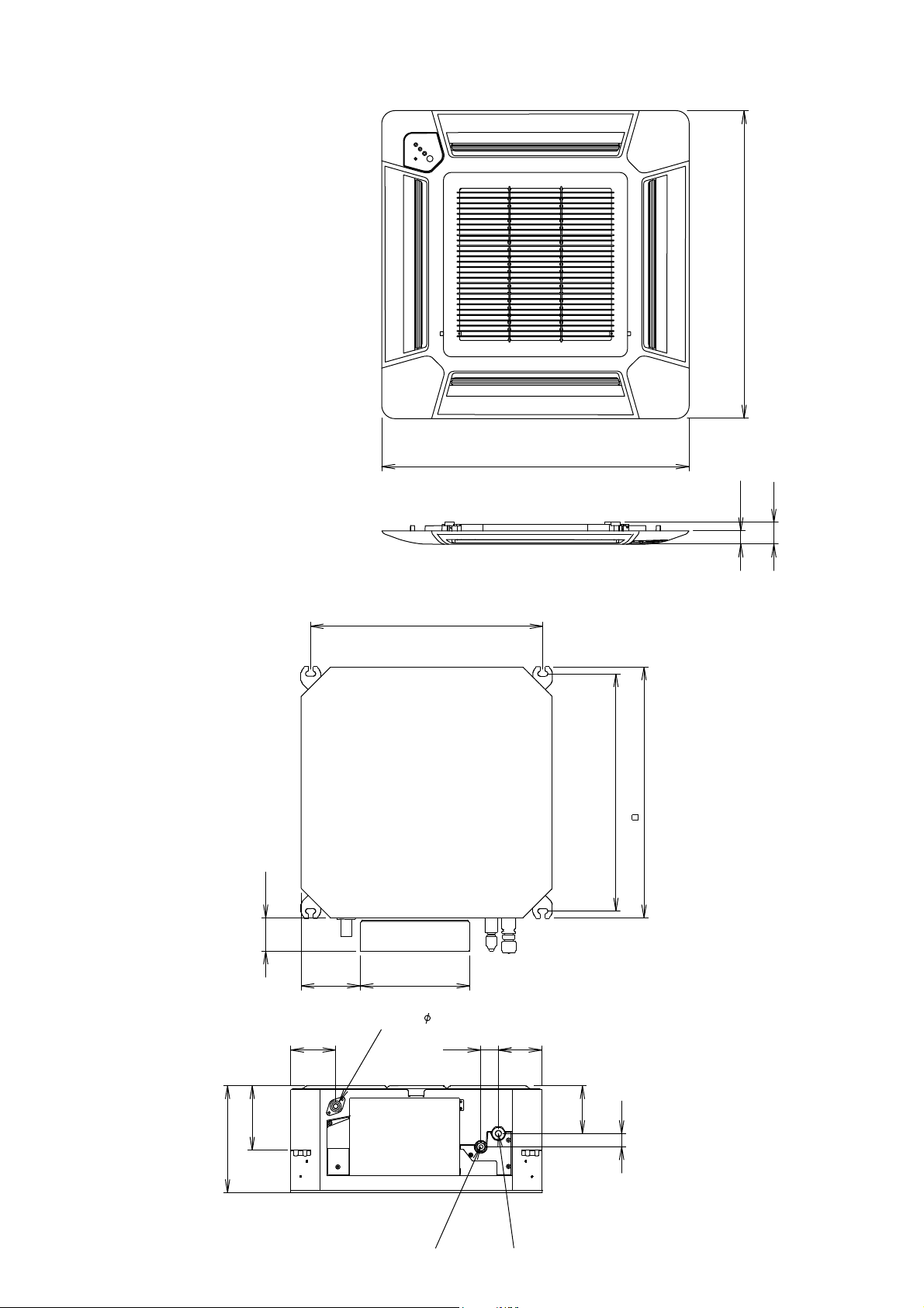
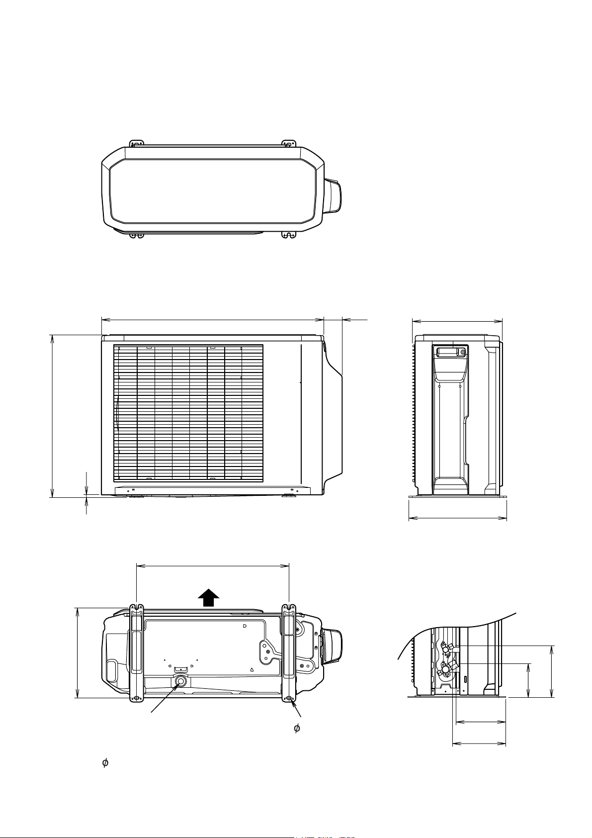
OUTLINE AND DIMENSIONS
Unit : mm
DECORATION PANEL
700
700
INDOOR UNIT
30
49
530(Hanging bolt position
)
)
TOP VIEW
570
Hanging bolt position
(
540
75
135
Drain pipe(0.D. 25.4
102
146
245
250
)
40
Liquid pipe Gas pipe
22007.0.23
99
30
108
SIDE VIEW
Page 4
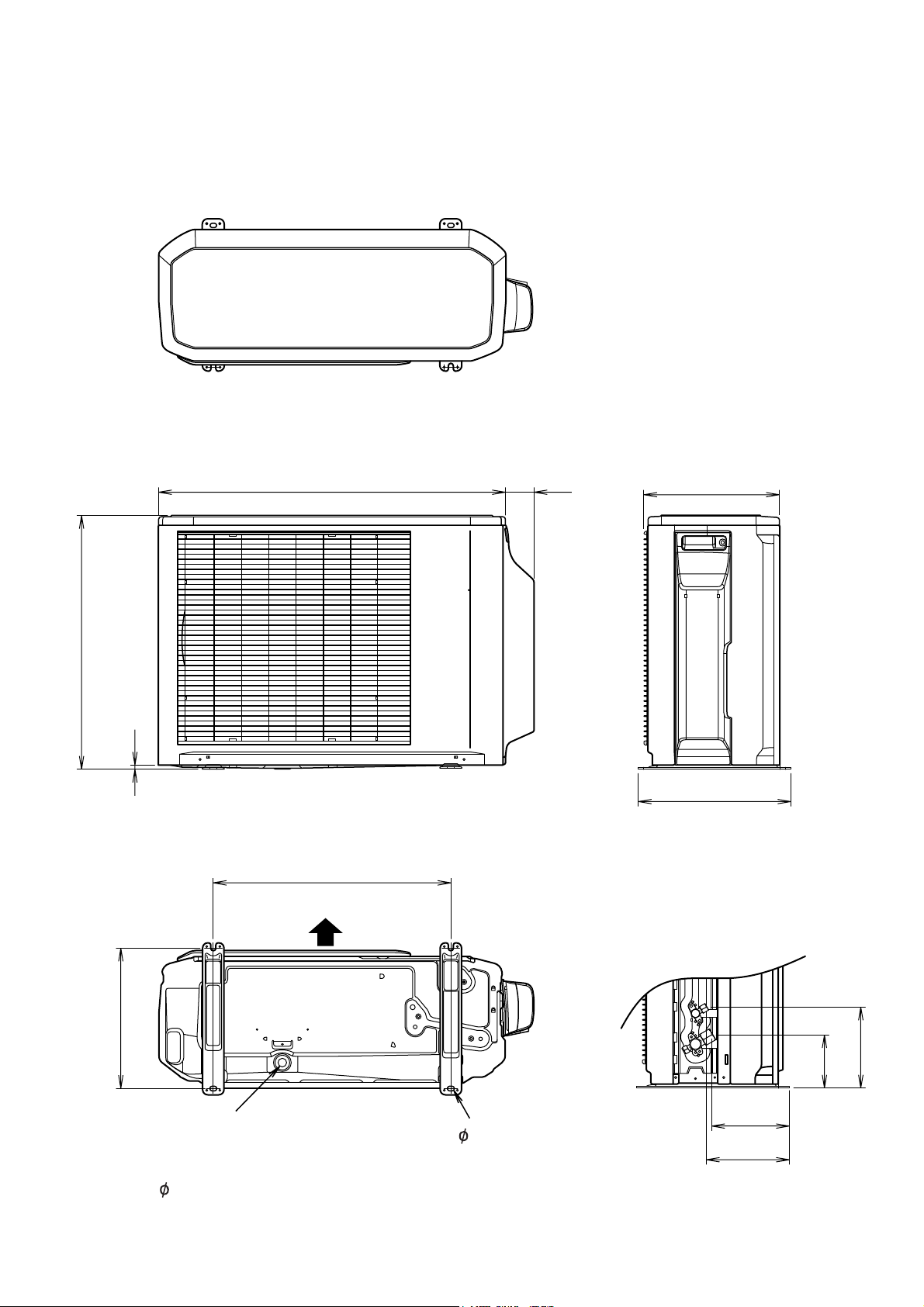
OUTDOOR UNIT
AOHA12LACL
AOHA14LACL
AOHA18LACL
Unit : mm
Top view
790
66
300
578
10
347
Front view
Side view
540
Air flow
320
Drain pipe
mounting place
( 20)
Bottom view
184
121
177
4- 10mm hole
189
32007.02.23
Page 5
OUTDOOR UNIT
AOHA24LACL
Unit : mm
Top view
790
66
315
578
10
347
Front view
Side view
540
Air flow
320
Drain pipe
mounting place
( 20)
Bottom view
184
121
177
4- 10mm hole
189
42007.02.23
Page 6
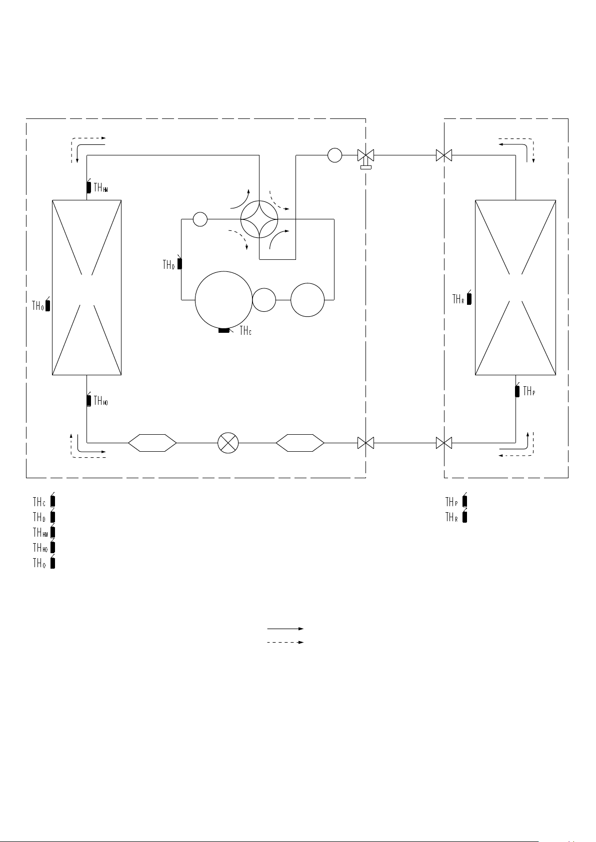
REFRIGERANT SYSTEM DIAGRAM
OUTDOOR UNIT
Heat
exchanger
INDOOR UNIT
Muffler
3-Way
valve
Muffler
4-Way
valve
Heat
exchanger
Accumulator
Compressor
: Compressor thermistor
: Discharge pipe thermistor
: Heat exchanger thermistor (Meddle)
: Heat exchanger thermistor (Out)
: Outdoor thermistor
<Refrigerant pipe diameter>
AUHA12LAL / AOHA12LACL
Liquid : 1/4" (6.35 mm)
Gas : 3/8" (9.52 mm)
AUHA14LAL / AOHA14LACL
AUHA18LAL / AOHA18LACL
Liquid : 1/4" (6.35 mm)
Gas : 1/2" (12.70 mm)
AUHA24LAL / AOHA24LACL
Liquid : 1/4" (6.35 mm)
Gas : 5/8" (15.88 mm)
Expansion
valve
2-Way
StrainerStrainer
<Refrigerant direction>
Cooling
Heating
valve
: Pipe thermistor
: Room thermistor
2007.07.27 5
Page 7
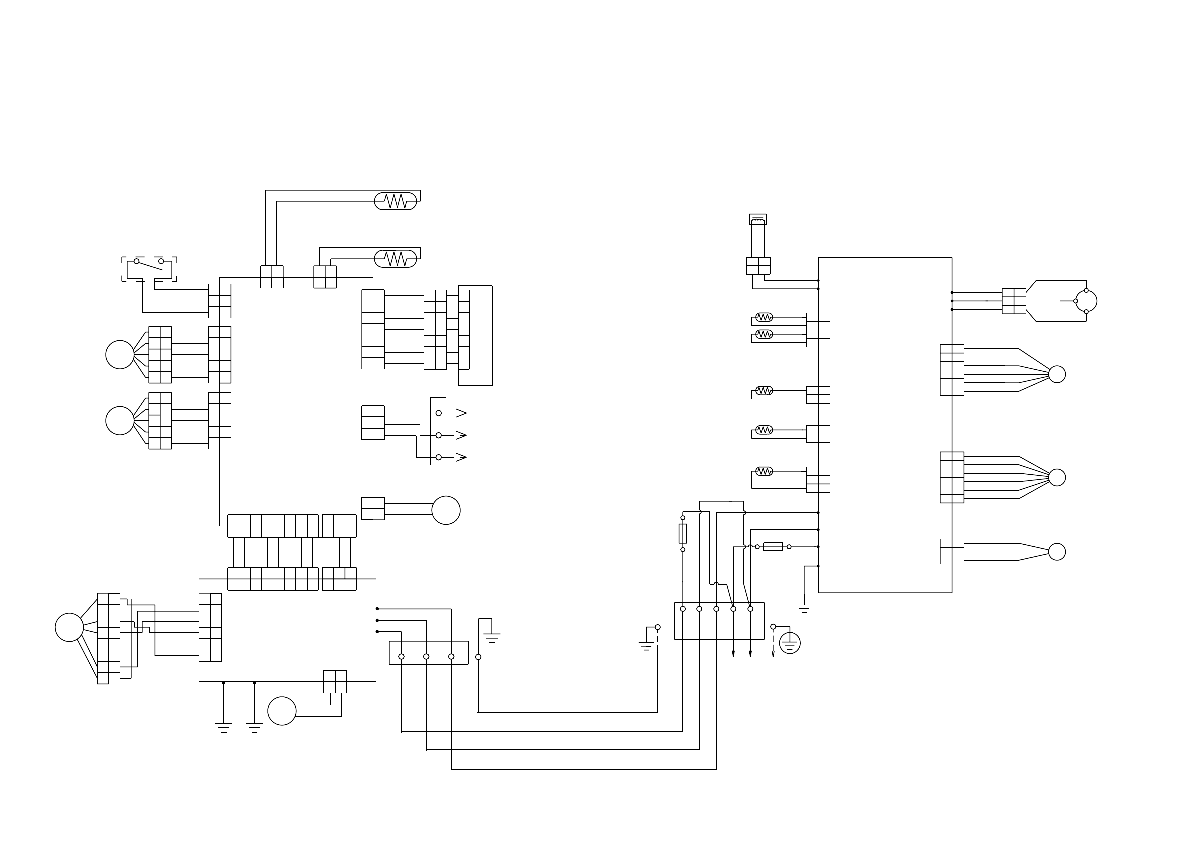
CIRCUIT DIAGRAM
INDOOR UNIT: OUTDOOR UNIT
GRAY
GRAY
PIPE THERMISTOR
REACTOR
STEP MOTOR
STEP MOTOR
FAN MOTOR
F M
FLOAT SWITCH
M
M
1
1
2
2
3
3
4
4
5
5
6
6
7
7
8
8
1
1
2
2
3
3
4
4
5
5
1
1
2
2
3
3
4
4
5
5
YELLOW
BLACK
BLACK
RED
ORANGE
YELLOW
PINK
BLUE
RED
ORANGE
YELLOW
PINK
BLUE
BROWN
WHITE
BLACK
RED
1
1
2
2
CN9
3
3
1
1
2
2
3
3
CN12
4
4
5
5
CONTROLLER PCB ASSY
1
2
3
4
5
CN11
( MAIN PCB )
1
2
3
4
5
1 2 3 4 5 678
1 2 3 4 5 678
GRAY
GRAY
1 2 3 4 5 678
1
1
2
2
3
3
CN105
4
4
5
5
6
POWER SUPPLY PCB ASSY
6
E101
E102
GREEN
2
1
2
1
CN5
CN4 CN1
GRAY
GRAY
GRAY
GRAY
GRAY
GRAY
4 5 678
CN104
YELLOW
M
GREEN
YELLOW
BLACK
BLACK
2
1
2
1
CN8
CN13
CN14
1 2 3
1 2 3
GRAY
1 2 31 2 3
1 2 3
CN101
CN106
1
1 2
CN6
GRAY
W105
W102
W101
2
ROOM THERMISTOR
BROWN
1
2
3
4
5
676
1
RED
2
ORANGE
3
YELLOW
4
WHITE
5
BLUE
PURPLE
7
1
2
3
4
5
67676
1
1
2
2
3
3
4
4
5
5
DISCHARGE PIPE THERMISTOR
PIPE THERMISTOR
7
INDICATOR PCB ASSY
COMPRESSOR THERMISTOR
RED
1
1
WHITE
2
3
121
2
3
2
BLACK
TERMINAL
2 1
TO REMOTE CONTROL UNIT
( OPTION )
3
FRESH AIR MOTOR
M
( OPTION )
PIPE ( MID ) THERMISTOR
OUTDOOR THERMISTOR
WHITE
FUSE
250V 5A
GRAY
RED
WHITE
BLACK
1 2
TERMINAL
3
TERMINAL
BLACK
1 3 L
( N )
BLACK
BLACK
2
YELLOW
YELLOW
12
2
1
WHITE
RED
BLACK
BLACK
BROWN
BROWN
BROWN
BROWN
BLACK
BLACK
BLACK
BLACK
RED
WHITE
BLACK
FUSE 250V 20A
GREEN
N
W10
W11
1
1
2
2
CN71
3
3
4
4
121
CN73
2
CONTROLLER PCB ASSY
121
1
2
3
2
1
2
3
W4
W2
W1
W3
( MAIN PCB )
CN72
CN70
RED
W7
W8
W9
CN801
CN40
CN30 4-WAY VALVE
RED
WHITE
BLACK
RED
1
1
2
2
BLACK
3
3
WHITE
4
4
YELLOW
5
5
BLUE
6
6
RED
1
1
BROWN
2
2
BLUE
3
3
ORANGE
4
4
YELLOW
5
5
WHITE
6
6
BLACK
1
1
2
2
BLACK
3
3
1
1
2
3
WHITE
2
3
BLACK
R (R)
COMPRESSOR
C M
S (S)
C (T)
F M
FAN MOTOR
EXPANSION VALVE
PMV
4WV
POWER SOURCE
DRAIN PUMP MOTOR
2007.10.24 6
Page 8
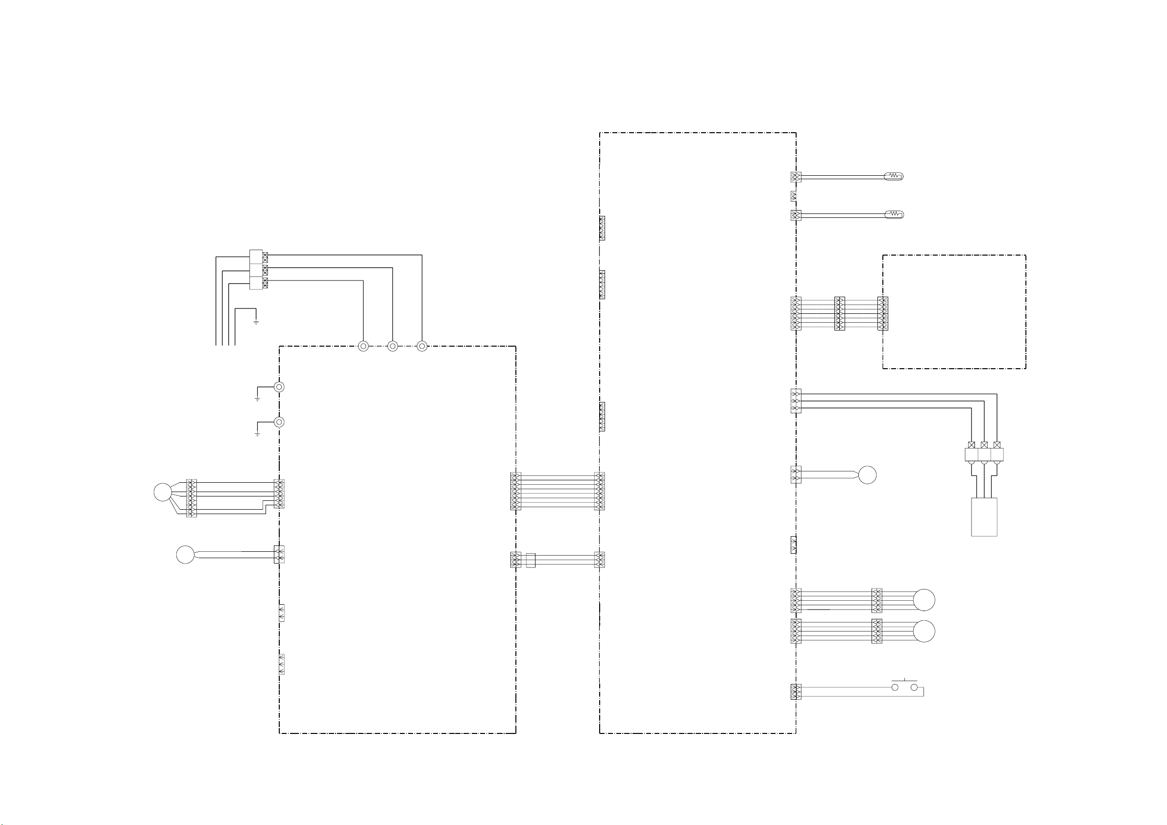
OUTDOOR UNIT
DC FAN MOTOR
F M
TERMINAL BOARD
UL1015 AWG16
GREEN
UL1015 AWG16
GREEN
1
UL1015 AWG22 RED
2
UL1015 AWG22 BLACK
3
UL1015 AWG22 WHITE
4
5
6
UL1015 AWG22 YELLOW
7
UL1015 AWG22 BROWN
8
INDOOR PCB CIRCUIT DIAGRAM
CONTROL UNIT
AUHA12LAL : EZ-0062AHSE
AUHA14LAL : EZ-0062BHSE
AUHA18LAL : EZ-00601HSE
AUHA24LAL : EZ-00602HSE
3
2(N)
1
UL1015 AWG20 RED
UL1015 AWG20 WHITE
UL1015 AWG20 BLACK
W101 W102 W105
E101
E102
POWER SUPPLY PCB ASSEMBLY
K06AL-0601HSE-P0
CN105-6
CN105-5
CN105
CN105-4
B5P6-VH-B
CN105-3
WHITE
CN105-2
CN105-1
CN104
B08B-PASK-1
WHITE
CN104-1
CN104-2
CN104-3
CN104-4
CN104-5
CN104-6
CN104-7
CN104-8
POWER DRAIVE
UL1430 AWG26 GRAY
UL1430 AWG26 GRAY
UL1430 AWG26 GRAY
UL1430 AWG26 GRAY
UL1430 AWG26 GRAY
UL1430 AWG26 GRAY
UL1430 AWG26 GRAY
UL1430 AWG26 GRAY
CN8
B02B-XASK-1-A
WHITE
CN7
B02B-XAYK-1-A
YELLOW
CN2-1
CN2-2
CN2-3
CN2-4
CN2-5
CN15-1
CN15-2
CN15-3
CN15-4
CN15-5
CN15-6
CN2
B5P-SHF-1AA
WHITE
CN15
B06B-XASK-1-A
WHITE
CN5
B02B-XAKK-1-A
BLACK
CN13
B07B-PASK-1
WHITE
CONTROLLER PCB ASSEMBLY
AUHA12LAL : K06AK-060EHSE-C1
AUHA14LAL : K06AK-060FHSE-C1
AUHA18LAL : K06AK-0601HSE-C1
AUHA24LAL : K06AK-0602HSE-C1
CN14
CN3-1
CN3-2
CN3-3
CN3-4
CN3-5
CN3-6
CN4-1
CN4-2
CN4-3
CN4-4
CN4-5
CN4-6
CN4-7
CN4-8
CN3
B06B-PASK-1
WHITE
CN4
B08B-PASK-1
WHITE
B03B-XAKK-1-A
BLACK
CN6
B02B-PAMK-1
GREEN
CN8-1
CN8-2
CN7-1
CN7-2
CN5-1
CN5-2
CN13-1
CN13-2
CN13-3
CN13-4
CN13-5
CN13-6
CN13-7
CN14-1
CN14-2
CN14-3
CN6-1
CN6-2
BLACK
BLACK
GRAY
GRAY
BROWN
RED
ORANGE
YELLOW
GREEN
BLUE
PURPLE
UL1430 AWG28
1
1
BROWN
2
RED
2
3
ORANGE
3
4
YELLOW
4
GREEN
5
5
6
BLUE
6
PURPLE
7
7
UL1430 AWG28
UL1430 AWG22 RED
UL1430 AWG22 WHITE
UL1430 AWG22 BLACK
M
FRESH AIR
( OPTION PARTS )
ROOM TEMP. THERMISTOR
PIPE TEMP. THERMISTOR ( MID )
INDICATOR PCB ASSEMBLY
K06AG-0600HSE-D0
CN201-1
CN201-2
CN201-3
CN201-4
CN201-5
CN201-6
CN201-7
CN201
S07B-PASK-2
WHITE
TERMINAL BOARD
3
1
2
DRAIN PUMP
M
BLACK
BLACK
CN106-1
CN106-2
CN103-1
CN103-2
CN102-1
CN102-2
CN102-3
CN106
B2P3-VH-B-E
BLUE
CN103
B2B-XH-AM
WHITE
CN102
B3B-XH-AM
WHITE
CN101
B03B-PASK-1
WHITE
CN101-1
CN101-2
CN101-3
DC SUPPLY
UL1430 AWG26 GRAY
UL1430 AWG26 GRAY
UL1430 AWG26 GRAY
EMI FILTER
ZCAT1518-0730
2 TURN
2007.10.24 7
CN1-1
CN1-2
CN1-3
CN1
B03B-PASK-1
WHITE
CN10
B02B-PAOK-1
ORANGE
CN11
B05B-XASK-1-A
WHITE
CN12
B05B-XARK-1-A
CN9
B03B-XARK-1-A
CN10-1
CN10-2
CN11-1
CN11-2
CN11-3
CN11-4
CN11-5
CN12-1
CN12-2
CN12-3
CN12-4
RED
CN12-5
UL1430 AWG26 RED
UL1430 AWG26 ORANGE
UL1430 AWG26 YELLOW
UL1430 AWG26 PINK
UL1430 AWG26 BLUE
UL1430 AWG26 RED
UL1430 AWG26 ORANGE
UL1430 AWG26 YELLOW
UL1430 AWG26 PINK
UL1430 AWG26 BLUE
RED
ORANGE
YELLOW
PINK
BLUE
RED
ORANGE
YELLOW
PINK
BLUE
M
M
REMOTE CONTROL UNIT
LOUVER
LOUVER
FLOAT SWITCH
CN9-1
CN9-2
RED
CN9-3
BLACK
BLACK
Page 9

INDOOR UNIT
CONTROLLER PCB ASSEMBLY ( MAIN PCB )
AUHA12LAL : K06AK-060EHSE-C1
AUHA14LAL : K06AK-060FHSE-C1
AUHA18LAL : K06AK-0601HSE-C1
AUHA24LAL : K06AK-0602HSE-C1
CN1
B03B-PASK-1
DC SUPLLY
CN2
B5P-SHF-1AA
TEST
CN3
B06B-PASK-1
SP PCB
CN4
B08B-PASK-1
POWER DRIVE
CN6
B02B-PAMK-1
FRESH AIR
CN10
B02B-PAOK-1
HEATER
1
2
3
1
2
3
4
5
1
2
3
4
5
6
1
2
3
4
5
6
7
8
13.5V
1
2
1
2
5V
13.5V
13.5V
13.5V
5V
C1
10/
50V
R15 - R18
10K <1/10W> x 4
5V
10K <1/10W> x 3
R24
R23
+
R26
10K
<1/10W>
<1/10W>
D4
1SS355
I C8
NJM7812
1 3
I
D1
1SS355
I C2
NJM7805
1
I
G
R32
R67 1.0K
<1/10W>
5V
R30
10K
<1/10W>
2
5V
12V
O
G
C2
2
+
10/
50V
5V
3
O
C3
0.01
<F>
R19
R22
1.0K <1/10W> x 4
R66
C35 C12 C11
1000P <R> x 3
R25
1.0K
<1/10W>
R31
10K
<1/10W>
5V
R34
R33
1.0K
10K
<1/10W>
R27
330
<1/10W>
1.0K <1/10W> X 3R63
C15
0.01
<F>
C17
0.01
<F>
R20
R21
R64
<1/10W>
1
C18
0.01
<B>
CUSTOM CODE
CUSTOM CODE
HEATING FAN DELAY
R65
C37
0.1
<F>
C14
1000P
<R>
5V
R29
R28
390
10K
<1/10W>
3
2
Q1
DTC124EKA
C16
0.01
<F>
5V
+
C32
100/
6.3V
C4 - C7
0.01 <F> x 4
JM1
JM2
JM3
C33
0.1
<F>
<1/10W>
Q3
DTC124EKA
3
2
5V
R1 - R3
10K <1/10W> x 3
C28
0.1
<F>
R70
10K
1
R4 - R6
1.0K <1/10W> x 3
SW1
CFS-0402MC
8
7
6
5
13.5V I C3
uLN2003ADR
9
SK
I 1
16
O1
I 2
O2
15
I 3
14
O3
I 4
13
I 5
O4
12
O5
I 6
I 7
11
O6
10
O7
8
GND
1
2
3
4
5
6
7
C8 - C10
0.1 <F> x 3
4
3
2
1
C36
0.47
<F>
5V
I C1
uPD78F0535
34
AVREF
39
I C
RST
36
43
P00
44
P01
P02
45
46
P03
33
P10
32
P11
31
P12
30
P13
29
P14
28
P15
27
P16
26
P17
18
P20
19
P21
20
P22
21
P23
22
P24
P25
23
P30
11
12
P31
13
P32
14
P33
38
XT1
37
XT2
41
X1
X2
40
AGND
25
9
GND0
42
GND1
R11 - R14
10K <1/10W> x 4
R7 - R10
1.0K <1/10W> x 4
AVDD
VDD0
VDD1
P34
P35
P36
P40
P41
P42
P43
P44
P45
P46
P47
P50
P51
P52
P53
P54
P55
P56
P57
P64
P65
P66
P67
P70
P71
P72
P73
P74
P75
2007.07.13 8
5V
ROOM TEMP. TH.
R44
10K
<1/10W>
R54
15.4K
<1/10W>
R53
28K
<1/10W>
uLN2003ADR
1
2
3
4
5
6
7
1
2
1
2
1
2
C25
10/
50V
12V
R48
10K
<1/10W>
I C4
1
I
2
I
I
3
4
I
5
I
I
6
I
7
GND
CN8
B02B-XASK-1-A
PIPE TEMP. TH. ( ENT )
CN7
B02B-XAYK-1-A
PIPE TEMP. TH. ( MID )
CN5
B02B-XAKK-1-A
5V
R49 - R51
10K <1/10W> x 3
5V
C26
+
0.01
<F>
D2
DAN217U
1 2
3
13.5V
9
SK
O1
16
15
O2
14
O3
O4
13
12
O5
11
O6
10
O7
8
12V
R52
10K
<1/10W>
D3
D1FS4A
5V
1
2
3
4
5
6
1
2
3
4
5
6
7
1
2
3
1
2
3
4
5
1
2
3
4
5
FLASH
CN15
B06B-XASK-1-A
INDICATOR
CN13
B07B-PASK-1
CN14
B03B-XAKK-1-A
REMOTE CONTROL UNIT
CN11
B05B-XASK-1-A
LOUVER ( UP / DOWN )
CN12
B05B-XARK-1-A
LOUVER ( RHIGT / LEFT )
5V
R45
10K
<1/10W>
R46
C31
1.0K
0.01
<1/10W>
<F>
<1/10W>
JM6
3
1
X1
5.00MHz
<CSTS>
JM5
0R0
2
0R0
C27
0.1
<F>
R37
10K
<1/10W>
35
10
24
15
16
17
57
58
59
60
61
62
63
64
1
2
3
4
5
6
7
8
53
54
55
56
47
48
49
50
51
52
R56
100K
0.1 <F>
C38
FLOAT SWITCH
CN9
B03B-XARK-1-A
1
2
3
5V
I C7
S80842
2
3
NC
VDD
1
4
OUT GND
R40
10K
<1/10W>
1
CS
VCC
2
SK
DO
3
D I
NC
6
GND
NC
I C5
BR93L56RF-WE2
C29
R57
1.0K
R58
1.0K
R62
1.0K
R43
10K
<1/10W>
R59
10K
<1/10W>
R60
49.9K
<1/10W>
R61
49.9K
<1/10W>
5V
0.1
<F>
<1/10W>
C30
0.1
<1/10W>
<F>
C34
0.1
<1/10W>
<F>
NC
R41 1.0K
<1/10W>
5V
C23
8
C13
4
0.1
7
5
<F>
0.01
<F>
5V
R55
10K
<1/10W>
C24
1000P
<R>
7
BA10393F
1
BA10393F
R47
390
<1/10W>
R42
47
<1/10W>
6
-
5
+
I C6-2
2
-
3
+
I C6-1
12V
13.5V
R35
1.0K
<1/10W>
B Z
BZ1
PKM13EPYH-4000-A0
C19 - C22
0.1 <F> x 4
DTC124EKA
1
Q2
3
2
R36
0R0
Page 10

INDOOOR UNIT
POWER SUPPLY PCB ASSEMBLY
K06AL-0601HSE-P0
L
I C26-14
F101
FSL 250 3.15
<EM>
FH102
VA101
470V
<TNR>
PFC5000-0702F
x 2
SA101
RA-362M
VA102
470V
<TNR>
W101
BLACK
W102
WHITE
FH101
LF101B
ELF17N015A
1
2
4
3
C104
0.47
<R46>
C105
0.01
<YE>
C106
0.01
<YE>
L101
REP28-15
15mH, 1.1A
E102
GREEN
<RS-2W>
C108
4700P
D102
1SR139-600
15V
+
R110
10K
<1/10W>
R103
62K
ZFT22B03-C
2
3
5
6
7
8
D106
D1FL20U
C110 0.047 <ECQB>
D103
D1FL20U
D104
MTZJ5.1B
<1/4W>
R109
330
D1FL20U
+
T101
D105
C111
100/
25V
D108
D2FL20U
12
10
1000/
A
C113
25V
C114
0.01
<KH>
C115
0.01
<KH>
R108
100
<1/2W>
13.5V
R111
+
10K
<1/10W>
340V
CN107
B2P3-VH-B-Y
D101
1
D3SB60
3
2
4
C107
100/
450V
+
C118
0.01
<KH>
1 2
CAPACITOR
<ECKE>
<RS-2W>
R106
<RS-2W>
C109
220P/
2.0kV
R105
1.5
75
<1/10W>
Q101
2SC5354
2
3
2SC1815
R107
100
1
Q102
1
R104
330K
<2W>
2
3
D107
RD16M
<B1>
<ECQM>
C112
330/
25V
POWER DRIVE
B08B-PASK-1
SERIAL I N
SERIAL I NT
SERIAL ON
DRAIN PUMP
DC FAN-OUT
DC FAN-FEEDBACK
EX. SIGNAL-OUT
EX. SIGNAL-I N
DC SUPPLY
I C26-10
CN104
CN101
B03B-PASK-1
E101
N
GREEN
CN105
R115
6.8K
<1/4W>
R113
330
<1/10W>
340V
B5P6-VH-B
6
5
4
3
2
1
G5NB-1A
4
2
I C101
TLP621
<GB>
4
3
<AG601>
DC FAN MOTOR
K101
1
3
L102
BLm18
5V
<AG601>
1
2
L103
BLm18
13.5V
R112
330
<1/10W>
C116
0.01
<B>
CN102
B3B-XH-AM
3
2
1
CN103
B2B-XH-AM
2
1
W105
RED
SERIAL
I C 1 0 5
H I 2 0 0 2 R 2
13.5V
RC101
120/0.1
5 4
5 4 3 2
3 2 1
1
5V
CN106
B2P3-VH-B-E
2
1
DRAIN PUMP
IC26-10
101418
6
N
K102
G5NB-1A
342
1
8
7
IC26-14
L
IC26-14
L
IC26-10
N
15V
I C103
<GB>
1
A
15V
R114
4.7K
<1/10W>
5V
1
2
3
4
5
6
7
8
1
2
3
1
2
I C104
TLP621
<GB>
15V
4
3
R116
1.0K
<1/4W>
<1/4W>
5V
C121
0.1
<F>
R117
820
+
C117
100/
25V
AA
13.5V
C120
0.1
<F>
TLP621
4
3 2
2007.07.13 9
Page 11

INDOOR UNIT
INDICATOR PCB ASSEMBLY
K06AG-0600HSE-D0
5V
TO CONTROLLER PCB ASSEMBLY ( MAIN PCB )
OPERATE
TIMER
FILTER CLEAN / FILTER SIGN
5V
REMOTE CONTROL SIGNAL
GRAND
MANUAL AUTO SWICTH
CN201
S07B-PASK-2 (LF) (SN)
R201 330 <1/4W>
R202 330 <1/4W>
1
2
R203 330 <1/4W>
3
4
5
6
7
2
4 3
EVQPAG04K
SW201
D201 SLR-325VC <RED>
D202 SLR-325MC <GREEN>
D203 SLR-325DC <ORANGE>
1
C202
+
10/
25V
C201
0.1
<F>
VCC
OUT
GND
2
1
3
2007.07.13 10
PHA201
P I C-37143TH5
Page 12

OUTDOOR PCB CIRCUIT DIAGRAM
INVERTER ASSEMBLY
AOHA12LACL : EZ-0060RHUE
AOHA14LACL : EZ-0060SHUE
AOHA18LACL : EZ-0069HUE
AOHA24LACL : EZ-006AHUE
TO INDOOR UNIT
POWER SOURCE
AC220 - 240V
50Hz
SERIAL
L
N
1
2
3
4
5
TERMINAL
W103
UL1015 AWG20
BLACK
W100
UL1015 AWG20
WHITE
EMI FILTER
ATFC-25-15-12
2 TURN
F202
5A - 250V
W102
UL1015 AWG20 BLACK
W101
BLACK
UL1015
AWG14
DISCHARGE THERMISTOR
OUTDOOR THERMISTOR
ATFC-25-15-12
F201
20A - 250V
PIPE THERMISTOR
EMI FILTER
2 TURN
EMI FILTER
ATFC-25-15-12
EARTH
1 TURN
UL1015 AWG14
BLACK
UL1015 AWG14
WHITE
UL1015 AWG20
UL1015 AWG16
GREEN
BLACK
BLACK
BROWN
BROWN
BLACK
BLACK
REACTOR
B
W1
( A-1 )
B
W2
( B-1 )
B
W4
RED
( D-1 )
B
W3
( C-1 )
1
CN71
2
B04B-PASK-1
3
WHITE
4
1
CN70
2
B03B-PASK-1
WHITE
3
UL3271 AWG16
WHITE
UL3271 AWG14
RED
W10 W11
B B
CONTROLLER PCB ASSEMBLY
AOHA12LACL : K06AX-0602HUE-C1
AOHA14LACL : K06AX-0603HUE-C1
AOHA18LACL : K06AX-0600HUE-C1
AOHA24LACL : K06AX-0601HUE-C1
CN30
B2P3-VH-B-C
BLACK
CN801
B5P6-VH-B-L
WHITE
W7
B
W8
B
B
W9
1
2
3
1
2
3
4
5
6
U
RED
V
WHITE
W
BLACK
UL3271 AWG16 x 3
BLACK
BLACK
RED
BLACK
WHITE
YELLOW
BROWN
EMI FILTER
RED
WHITE
BLACK
4-WAY VALVE
F M
COMPRESSOR
C M
DC FAN MOTOR
COMPRESSOR THERMISTOR
PIPE ( MID ) THERMISTOR
BROWN
BROWN
BLACK
BLACK
CN73
1
B02B-XAMK-1-A
2
GREEN
1
CN72
B02B-XH-AM
2
WHITE
2007.07.20 11
CN40
B6B-XARK-1-A
RED
1
2
3
4
5
6
RED
BROWN
BLUE
ORANGE
YELLOW
WHITE
EXPANSION VALVE MOTOR
M
Page 13

CONTROLLER PCB ASSEMBLY
AOHA12LACL : K06AX-0602HUE-C1
AOHA14LACL : K06AX-0603HUE-C1
AOHA18LACL : K06AX-0600HUE-C1
3
2
3
2
5V
R23
27K
4.7K
1%
1
2
3
4
5
6
7
8
W10
WHITE
ORANGE
R1
PFC / 58P
MAKING OF
CURRENT
DIRECTIVE
R21
10K
<1/10W>
R22 1.0K
<1/10W>
R147
R148
C123
2200P
<B>
CTDW / 34P
C14
0.1
<F>
V4-AC / 27P
V4-DC / 29P
ACFAN / 28P
REACTOR
W11
RED
2
3
W5
2
3
W6
ORANGE
4
PR / I C80-5
1
R157
4.7K
C138
2.2/
50V
DAN217U
+
4
1
R20 1.0K <1/10W>
C21
0.047
<B>
PFCEN / 14P
R150R151
195K <RN-1/2W> 1% x 4
15V
D110
DAN217U
2 1
3
1
2
D111
3
DAN217U
-12V
R144
22K
1%
R145
22K
1%
C124
2200P
<B>
R152
4.7K
1%
LED / 30P
SO / 32P
PR / 31P
CONTROL GND
D100
LL25XB60
LL25XB60
D101
1
+
4
-
1
+
4
-
15V
2 1
D105
3
-12V
C137
R155
0.1
<F>
R156
100K
1%
x 2
ZXL / 37P
S I / 48P
C20
0.1
<F>
DTC143EUA
2
Q103
DTC143EUA
15V
C130
0.1
<F>
R160
R159
4.7K
R161
C129
1000P
<B>
R143
39K
1%
9
-
8
10
+
I C104-3
BA2902F
R146
39K
1%
AC WAVEFORM DETECTION
FAN IN / 17P
FAN PWM / 2P
PFCSW / 35P
CT / 3P
TEST / 59P
PFC / 58P
TTXD / 60P
TAUX3 / 21P
CTDW / 34P
CP-POS / 47P
V4-AC / 27P
ACFAN / 28P
V4-DC / 29P
LED / 30P
PR / 31P
SO / 32P
IPM-TRIP / 33P
E2CS / 41P
EPV2 / 42P
EPV4 / 43P
EPV3 / 44P
TH / 10P
IPM-CR / 9P
DCV / 8P
ACV / 7P
TA / 6P
TE / 5P
TD / 4P
C500
0.1
<F>
R400 - R407
0.2 <1W> 1% x 8
10K 1% x 2
R127
R153
6
-
5
+
I C3-2
BA4560
R154
120K
Q102
5V
68K
1%
1%
7
5V
<1/10W>
R132
2.2K
2
3
1
3
2
I C105-1
BA2903F
R128
R142
1.2K
1%
R131
R162
68K
1%
+
-
10
1
120K 1%
1.5K
R137, R136 10K 1% x 2
R138 10K 1%
R140
10K
1%
R139
10K
1%
1
D109
RB751V
6
-
5
+
I C104-2
BA2902F
FULL WAVE RECTIFICATION
I C500
MB90462
17
P63
VCC
AVCC
P62
16
2
P00
P46
35
P12
P01
P17
3
P50
P13
P37
59
P36
58
P14
60
P40
P15
21
P16
MD2
34
P11
AVR
47
P26
P24
27
P02
P25
P03
28
P30
29
P04
P31
30
P05
P32
P06
31
P33
32
P07
P34
P10
33
P35
57
P60
C
P20
41
P61
42
P21
MD0
P22
MD1
43
P23
P44
44
10
P57
P43
P42
9
P56
P55
P41
8
7
P54
P45
RSTX
5
P52
P53
6
P27
AGND
P51
4
22
X0
GND
X1
23
GND
3
X500
8.00MHz
2
<CSTLS>
CURRENT DETECTION
R129
100K
1%
R130
220
1%
3
1
5V
R163
10K
1%
ZXH / 36P
6
-
5
+
I C105-2
BA2903F
7
D108
RB751V
56
11
25
26
40
36
37
38
39
12
45
46
50
51
52
53
54
55
14
15
18
20
64
63
62
61
1
19
48
13
24
49
C502
<F>
R126
100K
1%
I C103-1
BA4560
2
-
3
+
2
-
3
+
I C3-1
BA4560
C117
1.0
<B>
ZWRO-CROSS
DETECTION
7
( HIGH-SPEED )
R135
10K
1%
R141
10K
1%
R500
10K
0.1
C501
10/25V
15V
1
-12V
6
5
1
R166 3.9K
PFC CONTROL
D107
RB751V
R134
10K
1%
2
-
3
+
I C104-1
BA2902F
13
12
I C104-4
BA2902F
R502
1.0K
C503
0.1
<F>
+
BYPASS CAPACITOR
C119, C120
0.1 <F>
x 2
C139
I C103-2
7
-
BA4560
+
R122
R123
4.7K
1% x 2
R158 3.9K
3
1 12
D115
DAN217U
R118
10K
1%
R119
10K
1%
R133
10K
1%
1
-
14
+
5V
R503
10K
SERVICE
JM500
TAUX / 25P
E2SK / 40P
ZXH / 36P
ZXL / 37P
E2DI / 39P
EPV1 / 45P
PFC-TRIP / 46P
PFCEN / 14P
TMODE / 18P
MD1 / 64P
MD2 / 63P
TCK / 62P
TRXD / 61P
MDO / 1P
/ TRES / 19P
S I / 48P
R561
1.0K
C561
0.01
<F>
5V-2
+
2.2/
50V
I C102-2
BA2901F
3
2
D114
DAN217U
C111
4700P
<B>
R164
22K
C125
0.1
<F>
15V
-12V
U / 50P
X / 51P
V / 52P
Y / 53P
W / 54P
Z / 55P
R560
100K
GT30J122
R121
100K
1%
7
+
6
-
C113
2700P
<B>
5V-2
R116
15K
1%
R117
22K
1%
C115
0.1
<F>
C116
0.1
<F>
AOHA24LACL : K06AX-0601HUE-C1
POWER SOURCE
AC230V
50Hz
B2P3-VH-B-C
EARTH
GREEN
SERIAL
CN30
RED
L
BLACK
N
WHITE
4-WAY VALVE DRIVE
4-WAY VALVE
CN801
B5P6-VH-B-L
WHITE
FAN MOTOR
CN40
B06B-XARK-1-A
RED
EXPANSION VALVE
CN73
B02B-XAMK-1-A
GREEN
COMPRESSOR THERMISTOR
CN72
PIPE ( MID ) THERMISTOR
B2B-XH-AM
CN71
B04B-PASK-1
PIPE THERMISTOR
DISCHARGE THERMISTOR
CN70
OUTDOOR THERMISTOR
B03B-PASK-1
2007.07.20 12
LINE FILTER
W1
VA1
470V
<TNR>
VA2
470V
<TNR>
W2
SA1
RA-302M
W3
8 7 1
W4
SERIAL COMMUNICATION
C1
1.0
<LE>
L1
RCH4716
1
2
3
4
H Y I C 1
G K - 3 0 4 3 4 E
101418
6
0.01
<KH>
0.01
<KH>
5V
JM32
15V
L800
BL02Rn1
C802
0.1
<F>
12V
R10 4.75K
1%
R12
13K
5V
L70 BL02Rn1
R71
4.75K 1%
R72
13K
1%
R73
38.3K
1%
CR30
RE1201
0.1/120
R801
C800
1.0K
100/
<1/4W>
25V
+
R802
5V
560
<1/4W>
POW-GND
R803 10K
<1/10W>
DC FAN MOTOR COMMUNICATION CIRCUIT
12V
I C40
TD62064
2
3
O1
I 1
7
O2
6
I 2
11
I 3
9
O3
16
14
I 4
O4
GND1
4
1
COM1
5
GND2
8
COM2
12
GND3
10
NC1
R13
10K
R11
10K
R77
10K
NC2
15
C10
0.1
<F>
C71
0.1 <F>
C72
0.1
<F>
C73
0.1
<F>
C40
<F>
0.1
13
GND4
1%
TEMPERATURE SENSING CIRCUIT
R75
10K
R76
10K
JM31
15V
Q801
DTA143EUA
1
2
3
5V
2
1
D600
DAN217U
3
R804
EXPANSION VALVE CONTROL
R40 - R43
1.5K <1/10W> x 4
EPV3 / 44P
EPV4 / 43P
EPV2 / 42P
EPV1 / 45P
5V
R14
2.2K
1%
R17
R16
22K
22K
1%
1%
TH / 10P
C11
0.1
<F>
TE / 5P
SLR-332VR
TD / 4P
TA / 6P
FTR-F3
1
3
1.0K
SO / I C80-2P
V4-AC / I C80-3
V4-DC / I C80-4
PR / I C80-5
ACFAN / I C80-6
1
3
2
=
POW-GND
DC-F
1
2
3
4
5
6
L40
1
2
3
4
5
6
1
2
1
2
1
2
3
4
1
2
3
C75
0.1
<F>
C4
C5
5 432 1
5
3
4
SO / I C80-2P
<LE>
K30
2
12V
4
V4-AC / I C80-3P
Q800
DTC143EUA
3
1
C12
0.1
<F>
D80
<RED>
C801
0.01
<F>
I C10-1
BA2903F
3
2
6
-
5
+
I C10-2
BA2903F
12V
FAN PWM / 2P
2
FAN IN / 17P
15V
+
-
7
R80
2.2K
12V
C6
3.3
K33
G5NB-1A
2
JM30
5V
1
C13
0.1
<F>
LED INDICATOR
16
15
14
13
12
11
10
9
R18
10K
R19
1.0K
I C80
uLN2003
1C
2C
3C
4C
5C
6C
7C
COM
RUSH CURRENT
PREVENTION
ZPR0RCH400
12V
K1 DW12D1
<1/10W>
R149
1B
2B
3B
4B
5B
6B
7B
8B
E
Q100
5V
L130
ELC0607RA
C140
0.1
<F>
1
C142
0.1
<F>
C126
+
2.2/
50V
R168
22K
COMP
RESET
5V
2
VDD
1
OUTNCGND
I C560
S80842
D102
1NH42
R103
100
<1/2W>
R102
47K
R120 4.7K 1%
R125 4.7K
11
+
10
I C102-4
BA2901F
R171
4.7K
5V-2
R115
22K
1%
5
2
+
4
I C102-1
BA2901F
OVER CURRENT
DETECTION
R165
22K
C127
2.2/
50V
C131
<F>
3
4
1
5V
R124
4.7K
13
R112
10K
1%
C110
+
0.1
E2CS / 41P
E2SK / 40P
E2DI / 39P
2
3
1 2
5
7
3
0.1
<F>
LLQ2W661KEUBGC
660uF / 450V x 3
C103
0.1
<HCP>
GATE DRIVE
<1/4W>
<1/4W>
R109 22
R108 47
GATIN
VCC
S I
6
SO
D I
4
NC
GND
C105
I C100
TA8316
TC 74HC00AF
1
2
3
4
5
6
7
I C101
1
2
3
4
5
6
7
R101
4.7K
I C102-3
BA2901F
OVER VOLTAGE
DETECTION
14
14
13
13
12
12
11
11
10
10
9
8
C141
1000P
<B>
14
0.1
<F>
9
8
15V
C112
0.1
<F>
5V
C128
0.1
<F>
R169
22K
C132
C133
+
2.2/
2.2/
50V
50V
EEPROM
C572
1.0K
<1/10W>
R93, R92, R91, R90
MD0 / 1P
MD1 / 64P
MD2 / 63P
TEST / 59P
C100 - C102
+ +
+
F100
GDT 250 15
15A - 250V
FSL 250 3.15<EM >
3.15A - 250V
R104
220K
<2W>
PFC5000-0702F
15V
PFC-POWER-GND
L100 BL02Rn1
15V-2
C104
CONTROL GND
+
10/
BASE POINT
25V
GATE DRAIVE GND
5V
POW-GND
PFCSW / 35P
PFCEN / 14P
C106
R113
4.7K
1%
9
+
8
C136
0.01
<F>
I C102
BYPASS CAPACITOR
3
1 2
AVERAGE OF INPUT VOLTAGE RECTIFICATION
C134
+
0.1
<F>
I C570
M93C46
CS1
2
SK
3
D I
6
NC
10K x 4
PFC-TRIP / 46P
R167
0.1
10K
<F>
5V-2
R114
15K
1%
INPUT CURRENT ( RSM ) AVERAGE DETECTION
D112
DAN217U
5V
D106
DAN217U
231
C108
2.2/
50V
R111
10K
ACV / 7P
3
1 2
5V
+
C109
+
2.2/
50V
D113
DAN217U
5V
8
VCC
C570
4
DO
0.1
7
NC
<F>
GND
5
R570
10K
5V
MODEL SWITCHING
JM101
JM102
JM103
JM100 TEST
EXAMPLE OF AOH12LACL
DCV
R105, R106
195K
<RN-1/2W>
1%
R107
3.83K
1%
DCV Ave
DC VOLTAGE
DETECTION
R110
6.8K
C107
DCV / 8P
CT / 3P
DCV
F4
FH2
FH1
x 2
DCV-F
POW-GND
R203 330K
390 <1/10W> x 6
U / 50P
V / 52P
W / 54P
X / 51P
Y / 53P
Z / 55P
IPM-TRIP / 33P
C219
1000P
<B>
0.1
<F>
IPM-CR / 9P
REVERSE CURRENT DETECTION CIRCUIT
CP-POS / 47P
COMP
15V
D50
1SS355
D51
UDZS8.2B
L50
BLm21
<AG601>
L51
BLm21
<AG601>
D52
1SS355
R51
47
C50
47/
35V
POW-GND
D200 - D202
U1JU44 x 3
+
C205 0.1 <F>
C204 47 / 35V
R218
4.7K
<1/10W>
R204 - R209
R219
1.0K
R220
1.0K
5V
R339
10K
3
1
Q300
DTC114EUA
DCV-F
R52
470K
<1/8W>
1%
R53
510K
<1/8W>
1%
R54
510K
<1/8W>
1%
R55
510K
<1/8W>
1%
C51
+
1.0
<B>
SWITCH POWER SUPPLY
POWER-GND
R200
39
<1/2W>
+
R202 330K
C203 0.1 <F>
C202 47 / 35V
5V
D301
DAN217U
2
3
C320
0.15
<ECQB>
5V
R334
10K
1%
2
C300
100P
<CH>
CONTROL SOURCE
R56
150K
2200P
<2W>
UF4005
I C50
TOP243PN
1
M
2
S
3
S
4
C
+
IPM-G
R201 330K
C201 0.1 <F>
C200 47 / 35V
C206 - C208, C215 - C217
5V
1
2200P <B> x 6
PEAKLOAD CURRENT DETECTION
D302 RB751V
C311
1000P
<B>
R327
22K
R337
100K
I C302-1
BA2903F
1
5V 5V
1%
-
+
2
3
C339
0.01
<F>
R335 R336
R338
3.3K
1%
5V
R81
1.0K
<1/10W>
7
R83
I C302-2
27K
<1/10W>
C52
<E>
R57
0R0
BA2903F
RPZ-1F
1
2
3
4
5
T60
D53
8
S
S
7
5
D
15V
W
L300
ELC0607RA
U V
W7 W8 W9
+
C210 0.1 <F>
C209 0.1 <F>
C211 0.1 <F>
C212 0.1 <F>
D203 HZ24BP-TK-E
C221 0.1 <F>
C220 47 / 35V
C222 1.0 <F>
C213
0.022
<F>
IPM-G
R329 47K 1%
I C300-1
BA4560
1
R328
1.0K
7
I C300-2
BA4560
R333
10K 1% x 3
C330
1000P
<B>
15V
C85
+
10/
470P
25V
6
-
5
+
C84
0.1
<F>
10
9
8
7
6
D62
D1FL20U
2
-
3
+
R331
47K
1%
5
+
6
-
VIRTUAL NEUTRAL POINT
D304
DAN217U
C86
<B>
C87
330P
<B>
D60
D1FL20U
D61
D1FL20U
I C60
BA17805
C66
+
100/
25V
D64
1SS355
R330
R332
221
3 3
WVU
R305
R306
DAN217U
C64
+
330/
25V
1SS355
FSBB20CH60
10
11
12
13
14
15
16
17
18
19
20
C214
2200P
<B>
IPM-G
15V
C305
0.1
<F>
-12V
4.7K 1% x 2
R303
R301R302
R304
D303
1
D63
OG123
I
C69
+
100/
25V
I C200
21
1
VCC
NU
2
COM
3
I N
22
4
I N
NV
I N
5
VFO
6
23
CFOD
7
NW
CSC
8
9
I N
24
U
VCC
VB
VS
I N
25
V
VCC
VB
26
VS
W
I N
VCC
27
P
VB
VS
R210
1.0K
C306
0.1
<F>
195K <RN-1/2W>
1% x 6
REFERENCE OF
POSITION DETECTOR
R309
5.76K
1%
R310
143
1%
C65
+
470/
25V
C67
0.1
<F>
U V W
DCV
AOY24LACL is R211 - R216
R211
R212
R213
R214
R215
R216
R217
0.15
<1W>
1%
x 7
IPM-G
POW-GND
IPM-GND BASE POINT
R307, R308
195K
<RN-1/2W>
x 2
R311
8.66K
1%
15V
12V
R61
5V
10K
C68
+
100/
25V
-12V
Page 14

ERROR CONTENTS
INDOOR UNIT
Troubleshooting at the indoor unit display
(Troubleshooting at the display is available
either on the wired or wireless remote control.)
FILTER LAMP
(ORANGE)
TIMER LAMP
(GREEN)
The OPERATION, TIMER and FILTER lamp operate as follows table
according to the error contents.
Error contents
Indoor signal error
Wired remote controller abnormal
Indoor room temperature sensor error
Indoor heat exchanger temperature
sensor (middle) error
Indoor heat exchanger temperature
sensor (inlet) error
Float switch operated
Outdoor discharge pipe temperature
sensor error
Outdoor heat exchanger temperature
sensor (outlet) error
Outdoor temperature sensor error
Compressor temperature sensor error
2-way valve temperature sensor error
3-way valve temperature sensor error
Outdoor heat exchanger temperature
sensor (middle) error
Indoor manual auto switch abnormal
Power supply frequency detection error
IPM protection
CT error
Compressor location error
Outdoor fan error
Connected indoor unit abnormal
Outdoor unit computer communication
error
Indoor fan abnormal
Discharge temperature error
Exessive high pressure protection on
cooling
4-way valve abnormal
Pressure switch abnormal
Compressor temperature error
Active filter abnormal
PFC circuit error
: 0.5s ON/0.5s OFF (Flash)
OPERATION
lamp (Red)
(2 times)
(2 times)
(2 times)
(2 times)
(3 times)
(3 times)
(3 times)
(3 times)
(3 times)
(3 times)
(3 times)
(4 times)
(4 times)
(5 times)
(5 times)
(5 times)
(5 times)
(5 times)
(5 times)
(6 times)
(7 times)
(7 times)
(7 times)
(7 times)
(7 times)
(8 times)
(8 times)
: OFF
OPERATION LAMP
(RED)
MANUAL AUTO
TIMER lamp
(Green)
(8 times)
(2 times)
(3 times)
(4 times)
(6 times)
(2 times)
(3 times)
(4 times)
(8 times)
(2 times)
(4 times)
(2 times)
(3 times)
(5 times)
(6 times)
(7 times)
(8 times)
(2 or 3 times)
(2 times)
(3 times)
(4 times)
(5 times)
(6 times)
(2 or 3 times)
(4 times)
FILTER lamp
(Orange)
(2 times)
(3 times)
(4 times)
Troubleshooting at the wired remote control LCD
Self diagnosis
If an error occurs, the following display will be shown.
("EE" will appear in the set room temperature display.)
Unit number
Error code
SUMOTUWETH FR
Error code Error contents
01
13
26
Indoor signal error
27
00
02
04
28
09
0C
06
0A
15
1d
1E
29
20
2A
17
18
1A
1b
1F
1c
12
0F
24
Wired remote controller abnormal
Indoor room temperature sensor error
Indoor heat exchanger temperature sensor (middle) error
Indoor heat exchanger temperature sensor (inlet) error
Float switch operated
Outdoor discharge pipe temperature sensor error
Outdoor heat exchanger temperature sensor (outlet) error
Outdoor temperature sensor error
Compressor temperature sensor error
2-way valve temperature sensor error
3-way valve temperature sensor error
Outdoor heat exchanger temperature sensor (middle) error
Indoor manual auto switch abnormal
Power supply frequency detection error
IPM protection
CT error
Compressor location error
Outdoor fan error
Connected indoor unit abnormal
Outdoor unit computer communication error
Indoor fan abnormal
Discharge temperature error
Exessive high pressure protection on cooling
2c
16
2b
19
25
If "CO" appears in the unit number display, there is a remote controller
error. Refer to the installation instruction sheet included with the remote
controller.
SA
Ex. Self-diagnosis
132007.10.24
Page 15

OUTDOOR UNIT
Error contents
Thermistor malfunction
Abnormal discharge temperature
Current surge protection
CT abnormality
Compressor position detection malfunction
Fan malfunction
PAM voltage abnormality
Timer short
Compressor temperature protection (permanent stop)
PFC surge protection (permanent stop)
LED
on 0.1 sec / off 0.1 sec
on
on 0.5 sec / off 0.5 sec
on 2.0 sec / off 2.0 sec
on 0.1 sec / off 2.0 sec
on 5.0 sec / off 5.0 sec
on 5.0 sec / off 0.1 sec
on 1.0 sec / off 0.1 sec
on 2.0 sec / off 5.0 sec
on 5.0 sec / off 2.0 sec
2007.07.31 14
Page 16

PARTS
DECORATION PANEL
UTG-UFGA-W
1
10
7 10
7
5
12
10
10
11
2
3
4
8
9
Ref. Description
Part number
1 Decoration Panel
without Insulations
2 Display Panel 9375529024
3 Receiver Window 9375547011
4 Intake Grille
5 Long Life Filter
7 Flap Total Assy 9377760012
8 Hook Bracket
9 Grille Hook
10 Panel Cover without
Insulations
11 Indicator PCB Assy
12 Connector Cover
152007.10.25
9375525019
9375531010
9375533014
9375546014
9375532017
9375530013
9707371017
9375549015
Page 17

DECORATION PANEL
UTG-UFGA-W
Flap total assy
Motor holder assy
17
(connector : white)
(connector : red)
20
19
21
Ref. Description
17 Gear A 9375536015
19 Motor Holder 9375535018
20 Step Motor
(white connector)
21 Step Motor
(red connector)
Part number
9900139070
9900139087
162007.10.25
Page 18

INDOOR UNIT
35
33
37
71
72
43
34
38
Ref. Description
32 Cabinet A Assy 9375492014
33 Cabinet B 9375494018
34 Bell Mouse 9375503017
35 Drain Pan Sub Assy 9377765024
36 Wire Cover 9375516017
37 Pipe Cover 9375515010
38 Hook R 9375504014
39 Hook L 9375505011
43 Drain Cap 9375502010
71 Remote Control 9315885012
72 Remote Control Holder 9305642014
AUHA12LAL
AUHA14LAL
AUHA18LAL
32
39
36
Part number
AUHA24LAL
9375492014
9375494018
9375503017
9377765017
9375516017
9375515010
9375504014
9375505011
9375502010
9315885012
9305642014
172007.10.25
Page 19

INDOOR UNIT
42
47
41
42
40
49
46
56
53
45
44
Ref. Description
40 2 Stage Turbo Fan Assy 9375480011
41 Evaporator Assy 9372585085
42 Evaporator Holder 9375508012
44 Pump Assy 9900360047 9900360047
45 Drain Pump Holder B 9375518011 9375518011
46 Fan Motor 9602436019
47 Fan Motor Holder 9375552015
49 Separate Wall 9375506018
50 Float Switch 9900361037
52 Drain Hose 9375519018
53 Drain Port 9375520014
55 Distributor Assy 9371325316
56 Coupling Pipe Assy 9373038412
52
50
55
Part number
AUHA12LAL AUHA24LAL
AUHA14LAL
AUHA18LAL
9375480011
9372585054
9375508012
9602436019
9375552015
9375506018
9900361037
9375519018
9375520014
9371325316
9373038368
9375480011
9372585061
9375507015
9900360047
9375518011
9602436019
9375552015
9375506018
9900361037
9375519018
9375520014
9371325330
9373038375
2007.07.31
18
Page 20

INDOOR UNIT
CONTROL UNIT
61
62
Ref. Description
64
65
AUHA14LALAUHA12LAL
66
63
Part number
AUHA24LALAUHA18LAL
2007.07.31
61 Control Box Cover 9375512019
62 Control Box A 9375511012
63 Controller PCB Assy 9707393156
64 Puwer Supply PCB Assy 9707398021
65 Terminal 9306489045
66 Terminal 9703345012
-- Pipe Thermistor 9703297014
-- Room Thermistor 9703299223
9375512019
9375511012
9707393163
9707398021
9306489045
9703345012
9703297014
9703299223
19
9375512019
9375511012
9707393026
9707398021
9306489045
9703345012
9703297014
9703299223
9375512019
9375511012
9707393033
9707398021
9306489045
9703345012
9703297014
9703299223
Page 21

PARTS
OUTDOOR UNIT
7
9
1
6
3
5
4
8
2
Part number
Ref. Description
AOHA12LACL
AOHA14LACL
AOHA18LACL
AOHA24LACL
1 Top Panel Assy
2 Cover (Switch) Assy 9309237032
3 Cabinet Assy
4 Blow Down Grille
5 Cabinet Right Assy
6 Fan Ring
7 Grip
8 Emblem
9 Protective Net
2007.07.31 20
9309230057
9314809040
9308884015
9309236011
9308885012
9308880017
9315211019
9315319012
9309230057
9309237032
9314809019
9308884015
9309236028
9308885012
9308880017
9315211019
9315033017
Page 22

OUTDOOR UNIT
17
16
34
18
13
40
35
38
14
19
37
41
20
Ref. Description
AOHA12, 14, 18LACL
10 4-Way Valve
11 Pulse Motor Valve Assy
13 Condenser Assy
14 Thermistor Spring A
15 Thermistor Spring
16 Propeller Fan
17 Nut
18 Motor Bracket
19 Separator Assy
20 Base Assy
21 3-Way Valve Assy
22 2-Way Valve Assy
32 Expansion Valve Coil
34 Fan Motor
35 Compressor Assy
Thermistor Assy37
38
Heat Exchanger Thermistor
39 Solenoid Coil
9900047016
9311641018
9311382027
313728262708
9300089012
9309909014
9304902003
9308872012
9312971015
9308869081
9315159014
9313064013
9900057039
9602133017
9313763039
9900148027
9900403010
9970033018
40 Compressor Thermistor 9900156046
Reactor Assy
41
9900354015
Outdoor Thermistor-- 9900210045
Condenser Assy B-- --- 9315303011
Part number
AOHA24LACL
9900163013
9315310019
9315302014
313728262708
9357804002
9309909014
9304902003
9308872029
9312971015
9315296030
9315414014
9313062019
9900057039
9602451012
9315297037
9900148027
9900403010
9970055010
9900156046
9900354015
9900210045
15
39
37
10
11
32
22
21
2007.10.24 21
Page 23

OUTDOOR UNIT
26
43
42
29
30
28
27
Ref. Description
AOHA12LACL
26 Inverter PCB Assy
27 Fuse Holder 0501454012
28 Fuse Holder 0501456016
29 Fuse
30 Fuse 0600372163
Terminal42 9703874031
Inverter Case Assy43 9315690012
9707427035
0501454012
0501456016
0600382018
0600372163
9703874031
AOHA14LACL
9707427042
0501454012
0501456016
0600382018
0600372163
9703874031
Part number
AOHA18LACL
9707427011
0600382018
AOHA24LACL
9707427028
0501454012
0501456016
0600382018
0600372163
9703874031
931569001293156900129315690012
2007.07.31 22
Page 24

STANDARD ACCESSORIES
INDOOR UNIT
Name and Shape
Coupler heat
insulation
Special nut A
(large flange)
Special nut B
(small flange)
Template
(Carton top)
Remote
control
Remote
control
holder
Q'ty
Application
For indoor side pipe joint
2
For installing indoor unit
4
For installing indoor unit
4
For cealing openings cutting
1
Also used as packing
For air conditioner operation
1
For installing remote control
on the wall
1
OPTIONAL PARTS
Name and Shape
Wired remote
control
UTB-* YD
Air outlet
shutter plate
UTR-YDZA
OUTDOOR UNIT
Name and Shape
Drain pipe
Adapter assy
Summary
Unit control is performed by
wired remote control.
Install the plate at outlet
when carrying out 3-way
direction operation.
Q'ty
Application
For drain piping work.
1
9303029015
To connect 12,000 BTU model
1
9370244007
Battery
Tapping screw
DECORATION PANEL
Name and Shape
Connector cover
Screw
Screw
For remote control
2
For mounting the remote
control holder
2
Q'ty
Application
For covering connector
4
For mounting decoration panel
4
For mounting connector cover
1
232007.10.24
Page 25

0709G3265
 Loading...