

Page 1
SPLIT TYPE
AIR CONDITIONER
CASSETTE
Models
Indoor unit Outdoor unit
type
AUH54LUAS AOH54LJBYL
(50Hz)
CONTENTS
SPECIFICATIONS. . . . . . . . . . . . . . . . . . . . . . . 1
DIMENSIONS . . . . . . . . . . . . . . . . . . . . . . . . . . 2
REFRIGERANT SYSTEM DIAGRAM . . . . . . . 4
CIRCUIT DIAGRAM . . . . . . . . . . . . . . . . . . . . . 5
. . . . . . 8OUTDOOR PCB CIRCUIT DIAGRAM
ERROR CONTENTS . . . . . . . . . . . . . . . . . . .
DISASSEMBLY ILLUSTRATION . . . . . . . . . . 13
PARTS LIST. . . . . . . . . . . . . . . . . . . . . . . . . . 21
STANDARD ACCESSORIES . . . . . . . . . . . . . 23
11
7INDOOR PCB CIRCUIT DIAGRAM . . . . . . . .
Page 2
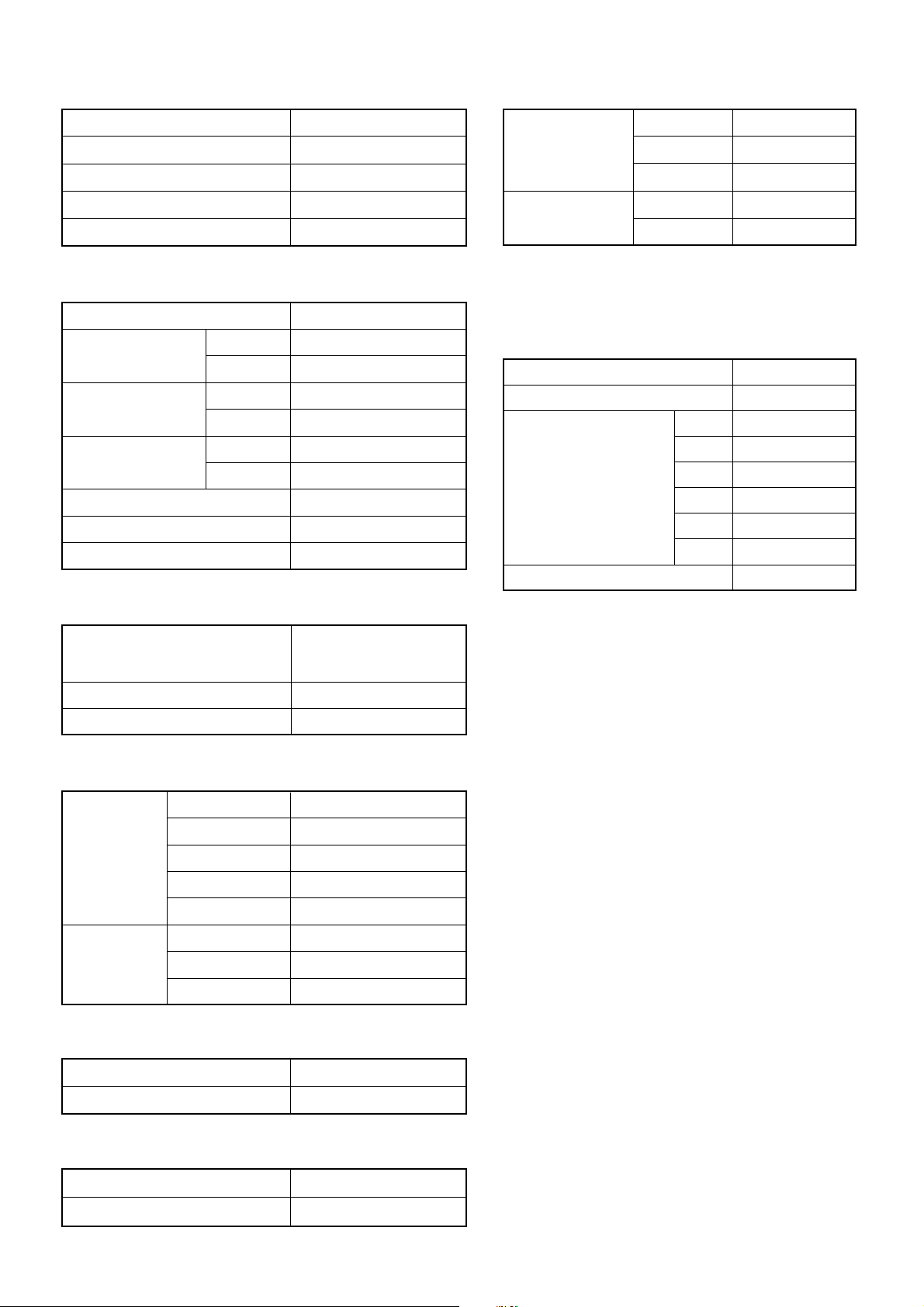
SPECIFICATIONS
TYPE
COOLING & HEATING
NOISE LEVEL
HIGH-SPEED
50.0 dB
INDOOR UNIT
OUTDOOR UNIT
COOLING CAPACITY
HEATING CAPACITY
ELECTRICAL DATA
POWER SOURCE
COOLING
RUNNING CURRENT
HEATING
COOLING
INPUT WATTS
HEATING
COOLING
E.E.R.
HEATING
STARTING CURRENT
MOISTURE REMOVAL
AIRCIRCULATION-High
AUH54LUAS
AOH54LJBYL
13.3 kW
16.0 kW
230V 50Hz
23.8 A
21.6 A
5.45 kW
4.95 kW
2.44 kW/kW
3.23 kW/kW
15 A
5.5 L/hr
1,700 m3/hr
INDOOR UNIT MED-SPEED
LOW-SPEED
COOL
OUTDOOR UNIT
HEAT
Note : Static pressure : 30Pa
Duct length : Inlet 1m, Outlet 2m
48.0 dB
45.0 dB
54.0 dB
55.5 dB
REFRIGERANT CHARGE (R410A)
MAX PIPE LENGTH
MAX PIPE HEIGHT
PIPE LENGTH
FULL CHARGE AMOUNT
ADDITIONAL REFRIGERANT
20 m
30 m
40 m
50 m
60 m
70 m
70 m
30 m
3,400 g
3,800 g
4,200 g
4,600 g
5,000 g
5,400 g
40 g / m
COMPRESSOR
TYPE
DISCRIMINATION
REFRIGERANT R410A
FAN MOTOR
DISCRIMINATION
HI-SPEED
INDOOR UNIT MED-SPEED
LO-SPEED
S-LO-SPEED
DISCRIMINATION
OUTDOOR
UNIT
UP FAN
DOWN FAN
DIMENSIONS
Hermetic type, 6 poles,
Inverter, Scroll
ANB33FCMMT
3,400 g
MFA-54PZM
680 r.p.m.
580 r.p.m.
500 r.p.m.
300 r.p.m.
MFE-60PO
850 r.p.m.
750 r.p.m.
INDOOR UNIT H x W x D
H x W x DOUTDOOR UNIT
296 x 830 x 830 mm
1,290 x 900 x 330 mm
WEIGHT
INDOOR UNIT GROSS / NET
GROSS / NETOUTDOOR UNIT
2006.03.07 1
55 kg / 40 kg
112 kg / 105 kg
Page 3
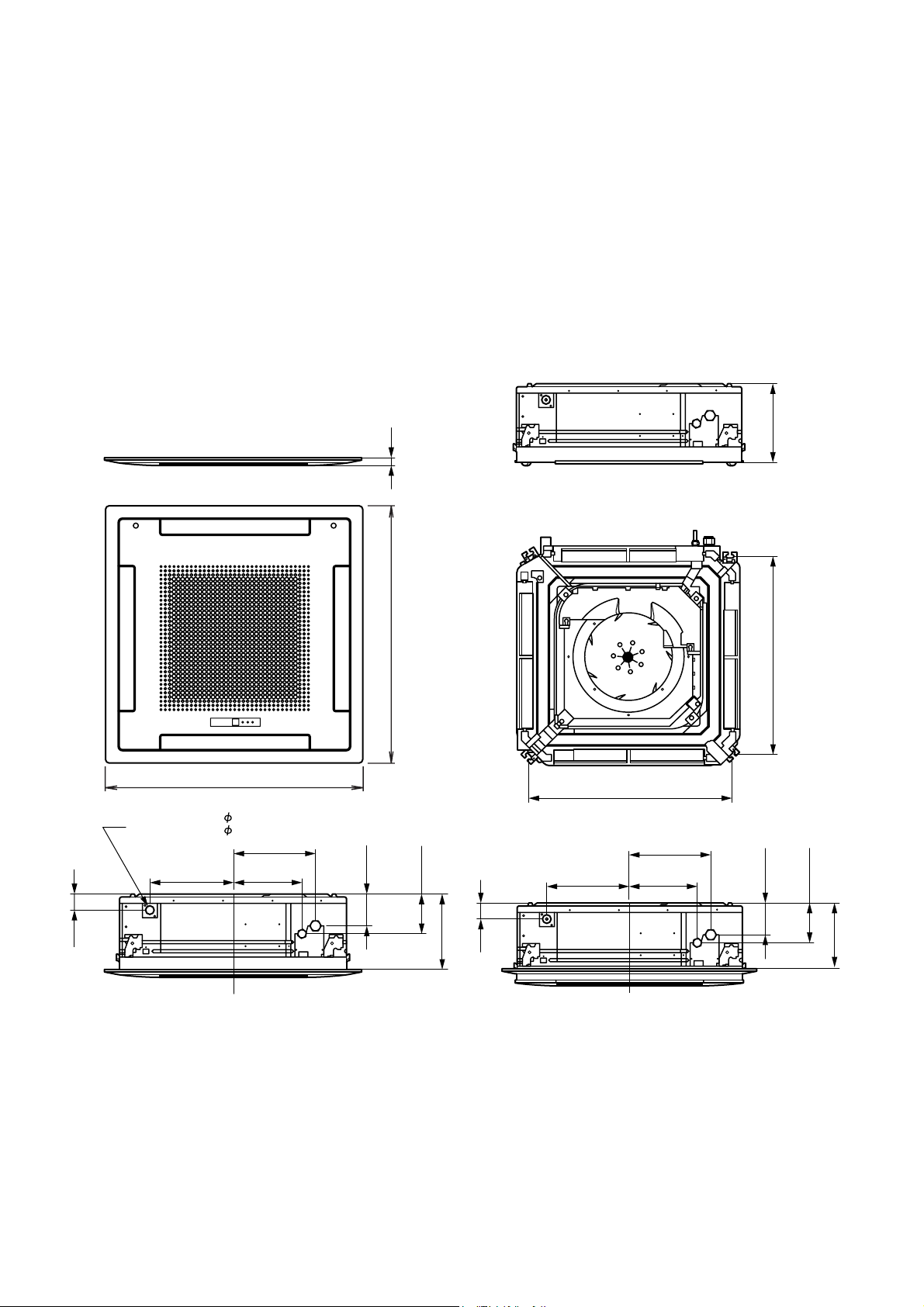
DIMENSIONS
(Unit : mm)
INDOOR UNIT
Model : AUH54LUAS
940
Drain Inside Dia. 32
Outside Dia. 37
305.5 248.5
298.5
30
940
750
298.5
120
(Small pipe)
(Large pipe)
150
305.5 248.5
296
750
120
150
(Large pipe)
(Small pipe)
60
(Drain pipe)
285
2006.03.07 2
60
(Drain pipe)
250
Page 4
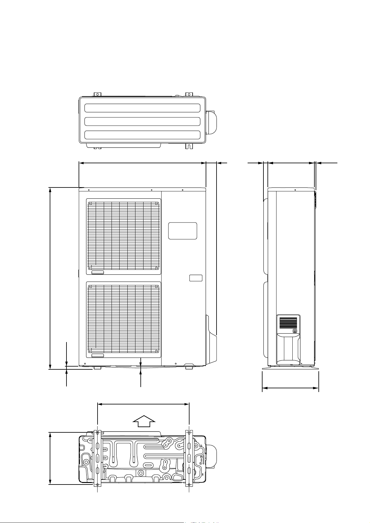
OUTDOOR UNIT
Model : AOH54LJBYL
(Unit : mm)
3177900 330 12
1290
21
9
400
650
Air Flow
370
2006.03.08 3
Page 5
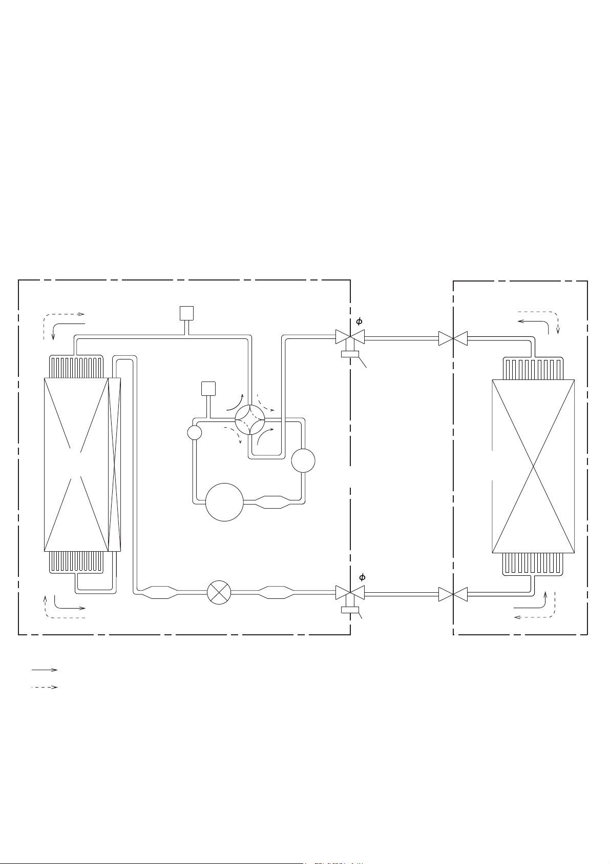
REFRIGERANT SYSTEM DIAGRAM
Models : AUH54LUAS / AOH54LJBYL
OUTDOOR UNIT
Condenser
High Pressure
Switch
Muffler
Pressure
Check Valve
4-way
Valve
Compressor
Expansion
Valve
INDOOR UNIT
Refrigerant Pipe
15.88mm (5/8")
Charging
Valve
Evaporator
Accumulator
Strainer
Refrigerant Pipe
9.52mm (3/8")
Strainer
Strainer
: COOL
: HEAT
2006.01.27 4
Charging Valve
Page 6
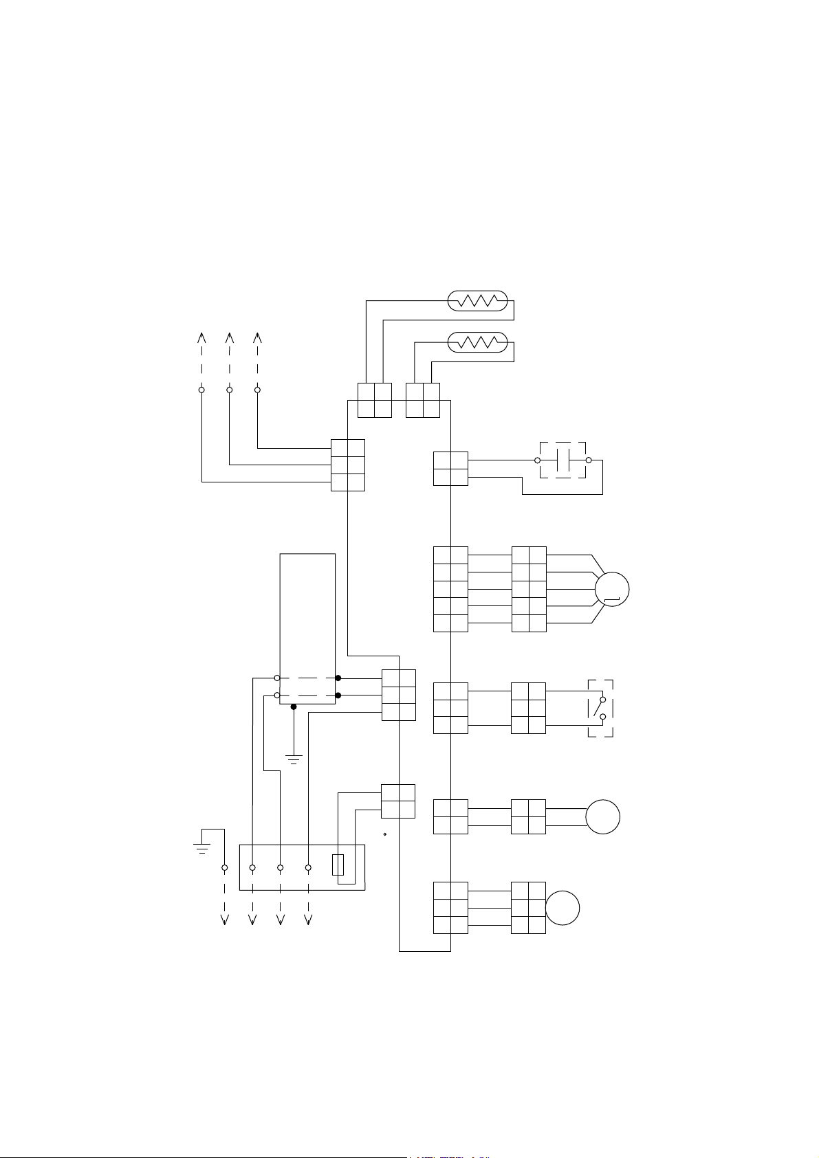
CIRCUIT DIAGRAM
Model : AUH54LUAS
TO REMOTE
CONTROL UNIT
TERMINAL
1
23
L
N
GREEN
RED
WHITE
BLACK
Use T 3.15A-250V
FILTER BOARD
Fuse on F101
1
2
3
BLACK
WHITE
1
2
3
GRAY
1 2
1 2
CN7
THERMISTOR
( PIPE TEMP. )
THERMISTOR
( ROOM TEMP. )
BLACK
1 2
1 2
CN8
BLACK
CN4CN10
1 1
2
2
FAN MOTOR
CAPACITOR
WHITE
WHITE
GRAY
CN17
STEPPING
MOTOR
CONTROL BOARD
1
2
3
5
BROWN
1
RED
2
ORANGE
3
YELLOW
454
WHITE
1
2
3
5
BROWN
1
RED
2
ORANGE
3
YELLOW
454
WHITE
M
FLOAT
1
1
CN1CN3
2
2
3
3
BLACK
1
1
2
2
BLACK
3
3
CN15CN6CN5
1
2
3
1
2
3
SWITCH
BLACK
BLACK
1 1
2 2
BLACK
WHITE
RED
GRAY
GRAY
1 2 3
THERMAL
FUSE 102 C
TERMINAL
TO OUTDOOR UNIT
2006.03.08 5
1 1
2 2
1
3
5
1
3
5
BLACK
BLACK
BLACK
WHITE
RED
DRAIN PUMP
MOTOR
YELLOW
121
YELLOW
2
2
2
1
1
FM
3
3
M
FAN
MOTOR
Page 7
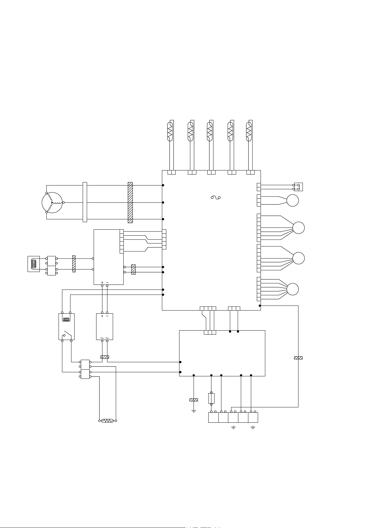
Model : AOH54LJBYL
CHOKE
COI L
RED
COMPRESSOR
U
V
W
BLACK
TERMINAL
EMI FILTER
RELAY
BLACK
CONNECTOR
WHITE
WHITE
BROWN
2T
GRAY
BROWN
THERMISTOR
( DISCHARGE )
1
2
3
4
5
1 2
CN21
U
W305
V
W304
W
W303
CN407
EMI FILTER
RED RED
WHITE
BLACK
ACTIVE
FILTER
MODULE
1T
BROWN
1
RED
2
ORANGE
3
4
5
YELLOW
6
BLACK
THERMISTOR
(PIPE )
1
2
CN22 CN23 CN26 CN25
F4 T 3.15A 250V
L1
L2
P
N
YELLOW
BLUE
W14
W15
EMI FILTER
2T
WHITE
VIOLET
RED
BLACK
W107
W108
DIODE BRIDGE
GRAY
EMI FILTER
2T
WHITE
BLACK
TM102
TM101
W3
BLUE
THERMISTOR
(OUTDOOR )
1
2
BROWN
THERMISTOR
(COMPRESSOR )
THERMISTOR
1
2
FUSE
PRINTED
CIRCUIT
BOARD
(MAIN)
1 2 3 1 2 3
BROWN
BLACK
1 2 3
CN1
CN34CN1
4
RED
BLACK
WHITE
W9W8
PRINTED CIRCUIT
BOARD (FILTER)
W6 W7 W1
(HEAT SINK )
1
CN37
CN30
CN800
CN801
CN27
W200
W2
BLACK
2
1
2
1
2
3
1
2
3
4
5
6
7
1
2
3
4
5
6
7
1
2
3
4
5
6
HIGH PRESSURE SW
RED
BLACK
BLACK
RED
BLACK
WHITE
YELLOW
BROWN
RED
BLACK
WHITE
YELLOW
BROWN
RED
BROWN
BLUE
ORANGE
YELLOW
WHITE
4WV
EV
SOLENOID
COIL
FM
FAN MOTOR 1
FM
FAN MOTOR 2
EXPANSION
VALVE COIL
EMI FILTER
3T
TERMINAL
EMI FILTER
ORANGE
ORANGE
1T
EARTH
POSISTOR
2006.03.08 6
BLACK
GREEN
WHITE
FUSE
10A
1 3 L
( N )
BLACK
WHITE
RED
2
N
EARTH EARTH
Page 8
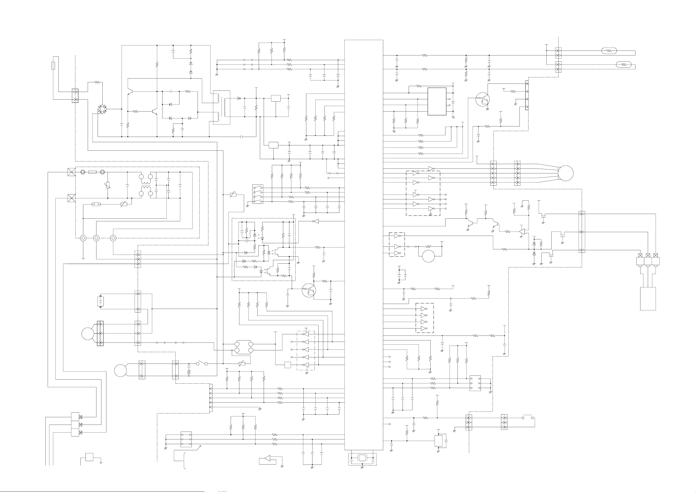
INDOOR PCB CIRCUIT DIAGRAM
Model : AUH54LUAS
C6
R5 62K
4700P
<RS - 2W>
<ECQM>
R7 330
<1/4W>
C103
0.01
<KH>
C104
0.01
<KH>
JM5
D5
1SR139-600
D10
1SR139-600
C7 0.047
<ECQB>
D2
D1FL20U
D3
MTZJ5.1B
C105
0.022
<YE>
C106
0.022
<YE>
CN6
B2P3-VH-B-E
BLUE
NO.1
NO.2
NO.3
+
JM8
CN6-2
CN6-1
SW1
DSS803
R6 100
<1/2W>
D4
D1FL20U
C8
100/
6.3V
C101
0.22
<LE>
THERMAL FUSE
GRAY
UL1015 AWG18 BLACK
UL1015 AWG18 WHITE
OUTDOOR UNIT
GRAY
CN3-2
CN3-1
CN3
53406-9910
TM101
TM102
UL1015
AWG16
GREEN
FAN CAPACITOR
8uF 400VAC
UL1015 AWG18 RED
TERMINAL BOARD
1
2
3
POWER SOURCE
230V
50Hz
R1 3.3
<RC - 5W>
F101
L
3.15A
<BET>
FH102
FH101
N
SA101
RA-362M
E101 W103 W104
F M
FAN MOTOR
E
D1
D3SB60
C5
+
100/
450V
VA102
470V
<TNR>
VA101 470V
<TNR>
K01AL-040GHSE-PO SERIES POWER PWB
UL1015
AWG18
UL1015 AWG18 WHITE
UL1015 AWG18 RED
UL1015 AWG20
WHITE
UL1015 AWG20
WHITE
UL1015 AWG20
BLACK
UL1015 AWG20
WHITE
UL1015 AWG20
RED
BLACK
DRAIN PUMP
M
YELLOW
YELLOW
R4 330K
<SPRH - 2W>
Q1
2SC4236
R3 100
<1/10W>
R2 1.5
<RS - 2W>
ELF20N018A
C102
0.22
<LE>
LF101
CN1
B3P5-VH-B-C
BLACK
CN4
B2P3-VH-B-Y
YELLOW
Q2
2SC1815
CN1-1
CN1-2
CN1-3
CN4-1
CN4-2
CN5-1
CN5-2
CN5-3
CN5
B3P5-VH-B
UL1015 AWG22
BLACK
UL1015 AWG22
BLACK
CUSTOM CODE CHANGER
CUSTOM CODE CHANGER
CUSTOM CODE CHANGER
SWITCHING TRANSFORMER
T1
ZFT29B01
PRIMARY
K4
G5NB-1A
DC12V
C3 0.22 <RE>
R88 120
<RS - 1/2W>
CN9 B5P-SHF-1AA
CN9-1
CN9-2
TEST
AUTO RESTART
ROOM TEMPERATURE CORRECTION
( HEATING OPERATION )
ROOM TEMPERATURE CORRECTION
( HEATING OPERATION )
CN9-3
CN9-4
CN9-5
R15 - R17
10K <1/10W> x 3
D6
D2FL20U
R8 10K
<1/10W>
SECONDARY
C54
0.01
<F>
VA1 470V
<TNR>
18
14
10
5V
10K <1/10W> x 4
R93 R94 R95 R96
SSR1
G3MC-202PL-VD
5V
5V
R39
R38 R37
JM1
JM2
JM3
14V
C9
+
1000
/25V
R29 - R32
10K <1/10W> x 4
C
SW2
DRS4016-5
I C10 H I 2002
+
-
VA2 470V
<TNR>
10K <1/10W> x 3
I C11-1
BA10358
1
5V
R18 - R20
1.0K <1/10W> x 3
I C2
12V
7812
O
I
G
C11
+
10/
25V
I C3
7805
I
8
4
2
1
5V
O
G
C13
0.1
<F>
R35 1.0K <1/10W>
R36 1.0K <1/10W>
5V
1
4
C17
0.01
<F>
14V
NC
NC
NC
K 4
R21 - R24
10K <1/10W> x 4
R25 - R28
1.0K <1/10W> x 4
R42 1.0K <1/10W>
R41 1.0K <1/10W>
R40 1.0K <1/10W>
3
+
2
-
C21
0.01 <F> x 3
10K <1/10W> x 4
C14
100/
6.3V
R97
R98
C15
+
0.1
<F>
R59
5V
NC
R33 1.0K <1/10W>
R34 1.0K <1/10W>
C29
C28 C27 C26
0.01 <F> x 4
10
7
I C5 (1/7)
uPA2003GR
R14 10K
5
<1/10W>
2
3
5V
R10
10K
<1/10W>
14V
11 6
12
13 4
14 3
15 2
Q3
DTC124EKA
9
5
8
I C5 (5/7)
uPA2003GR
C22 - C25
0.01 <F> x 4
C30
R9 390
<1/10W>
0.01 <F> x 3C10 C12
R99
C47
0.1
<F>
CR1
0.01
<F>
C19C20
JM10
CR6
0.01
<F>
1
2
3
54
55
66
65
74
68
75
7
4
67
33
71
72
56
57
58
59
41
42
63
40
39
38
37
36
43
44
45
46
19
20
21
CONTROLLER PCB ASSEMBLY ( MAIN PCB )
I C 1
P15
P16
P17
uPD780058BGC
-131-8BT-A
P122
P123
P05
P04
VDD0
VDD1
AVRF0
AVRF1
AVSS
VSS0
VSS1
I C
XT2
P124
P125
P126
P127
P65
P66
P02
P64
P63
P62
P61
P62
P67
P30
P31
P32
P40
P41
P42
70
1
2
P10
P11
P70
P71
P72
P131
P46
P24
P23
P47
P57
P56
P50
P27
P26
P25
P22
P21
P20
P130
P00
P121
P36
P33
P01
P55
P120
P37
P35
P34
P03
P12
P13
P14
P52
P53
P54
P45
P44
P43
XT1
P51
RESET
X2X1
69
3
X1
CSTS0500MG03-T
76
C32
1000P
<R>
77
C35
1000P
<R>
8
9
10
6
25
15
14
26
R100 10K <1/10W>
35
34
27
18
17
16
13
12
11
5
61
10
53
7
11
6
50
16
1
47
5V
C41
+
10/
25V
62
CR5
1000P
<R>
32
52
51
49
48
64
78
79
80
29
NC
CR2 CR3 CR4
30
NC
31
NC
10K <1/10W> x 3
24
23
22
C31
0.01
<F>
73
28
NC
R55
10K
<1/10W>
60
C44
0.1
<F>
K01AL-0503HSE-C1
R44 1.0K
<1/10W>
R46 1.0K
<1/10W>
R50 10K <1/10W>
4
DO
D I
3
CK
2
1
CS
I C7 BR93L46RF
R77 - R79
10K <1/10W> x 3
R58 10K <1/10W>
R75 10K <1/10W>
R76 10K <1/10W>
1 16
7 10
5 12
14V
9
13
4
3
2
15
1
8
I C4 (7/7)
uPA2003GR
R57 1.0K
<1/10W>
R56
I C6 (3/7)
uPA2003GR
B Z
C42 0.01
<F>
R54 47
<1/10W>
5
12
4
13
3
14
2
15
R81 1.0K <1/10W>
R72 1.0K <1/10W>
R53 10K
<1/10W>
R71 1.0K <1/10W>
C16
C43
0.01
0.01
<F>
<F>
RJ1 1.0K
<1/10W>
C49
5V
0.01
<F>
3
I C8
PST600C
5V
8
VCC
7
NC
C39
0.1
NC
6
<F>
GND
5
I C5 (1/7) uPA2003GR
116
NC
14
NC
NC
16
R60
NC
10K
<1/10W>
Q5
2SC2712
14V
BZ1
PKM13EPY-4000
5V
C40
0.01
<F>
I C6 (4/7)
uPA2003GR
CR7
0.01
<F>
R70 R69 R80
5V
RJ2
10K
<1/10W>
CN15-1
CN15-2
C45
0.1
<F>
CN15-3
5V
1
2
NO3 FAN DELAY CHANGER
(HEATING OPERATION)
NO2 FAN CHANGER
NO1 REMOTE CONTROL
FUNCTION REVERSED
5V
5V
R43 10K
<1/10W>
(1%)
R45 49.9K
<1/10W>
(1%)
R61 10K
<1/10W>
3
2
R49 1.0K
<1/10W>
C38
0.01
<F>
14V
CN10-1
CN10-2
CN10-3
CN10-4
CN10-5
CN10
B5B-XASK-1-A
1
Q6
2SC2712
5V
C34
0.1
<F>
C37
0.1
<F>
Q4
DTC124EKA
UL1430 AWG28
R63 15.4K
<1/10W>
(1%)
3
2
R65 390
<1/10W>
5V
R68 10K
<1/10W>
NO.3
NO.2
NO.1
UL1430 AWG22
BLACK
UL1430 AWG22
BLACK
R52
10K
<1/10W>
C1 0.1
<F>
R51 1.0K
<1/10W>
R67 1.0K
<1/10W>
5V
10K <1/10W>
x 3
SW4
DSS803
CN15 B3B-XARK-1-A RED
CN14
B4B-XH-AM
R47 390
5V
<1/10W>
5V
R48
10K
<1/10W>
BROWN BROWN
RED RED
ORANGE ORANGE
YELLOW YELLOW
WHITE WHITE
R64 28K
<1/10W>
(1%)
12V
1
R62 4.7K
<1/10W>
I C11-2
BA10358
12V
7
D7
DA226U
5
+
6
-
5V
FLOAT SWITCH
BLACK
BLACK
CN14-4
CN14-3
CN14-2
CN14-1
12V
HA
JEM-A
12V
L2 0.022
<DSS306>
R66 10K
<1/10W>
5V
CN8
CN7
L4 0.022
<DSS306>
B2B-XASK-1-A
CN8-1 BLACK
CN8-2 BLACK
CN7-1 GRAY
CN7-2 GRAY
B2B-XAKK-1-A BLACK
M
CN17 B3B-XAKK-1-A BLACK
CN17-1
CN17-2
CN17-3
L3 0.022
<DSS306>
LOUVER
( UP / DOWN )
UL1430 AWG22 RED
UL1430 AWG22 WHITE
UL1430 AWG22 BLACK
ROOM TEMPERATURE THERMISTOR
PIPE TEMPERATURE THERMISTOR
TERMINAL BOARD
3 2
1
REMOTE CONTROL UNIT
2006.03.07 7
Page 9

Model : AOH54LJBYL
POWER SOURCE
230V
50Hz
INDOOR UNIT
DC FAN MOTOR-1
DC FAN MOTOR-2
EXPANSION VALVE
F.M.
F.M.
M
4-WAY VALVE
PRESSURE SWITCH
COMPRESSOR TEMPERATURE THERMISTOR
HEAT SINK TEMPERATURE THERMISTOR
DISCHARGE TEMPERATURE THERMISTOR
PIPE TEMPERATURE THERMISTOR
OUTDOOR TEMPERATURE THERMISTOR
N
L
3
N
L
RED
BLACK
WHITE
YELLOW
BROWN
RED
BLACK
WHITE
YELLOW
BROWN
RED
BROWN
BLUE
ORANGE
YELLOW
WHITE
BLACK
BLACK
RED
RED
BROWN
BROWN
BLACK
BLACK
BROWN
BROWN
BLACK
BLACK
BLUE
BLUE
UL1015 AWG20
WHITE
UL1015 AWG20
BLACK
UL1015 AWG20
WHITE
UL1015
F202
AWG20
FSL 250
BLACK
10 (EM)
250V 10A
EMI FILTER
TFC-16813
1TURN
UL1015
AWG20
RED
EMI FILTER
RFC-8
3TURN
W200
SERIAL A
B
CN800
1
B7B-XASK-1-A
WHITE
2
3
4
5
6
7
CN801
B7B-XAKK-1-A
1
BLACK
2
3
4
5
6
7
CN27
1
B6B-XARK-1-A
RED
2
3
4
5
6
CN30
179844-1
1
WHITE
3
CN37
B2B-XARK-1-A
RED
1
2
CN36
B2B-XASK-1-A
1
WHITE
2
CN26
B2B-XAMK-1-A
GREEN
1
2
CN25
B2B-XAKK-1-A
1
BLACK
2
CN21
B2B-XH-AM
1
YELLOW
2
CN22
B2B-XH-AM
1
RED
2
CN23
B2B-XAEK-1-A
1
BLUE
2
UL1015
AWG20
BLACK
UL1015
AWG16
GREEN
EARTH
W1
W6
B
W2
W7
B
POWER SUPPLY PCB ASSEMBLY
K04BA-0400HUE-P0
W3
B
03 VH / SIN
1015 L250
CN1
B3B-XASK-1-A
WHITE
CT OUT
TM101
TM102
W8
W9
B
B
1
2
3
UL1015 AWG12 BLACK
UL1015 AWG12 WHITE
UL1015 AWG20 BLACK
UL1015 AWG20 WHITE
UL1007 AWG24 BLACK
UL1007 AWG24
UL1007 AWG24
INVERTER ASSEMBLY
EZ-0057HUE
R200
ZPR0YCE400A300
UL1015
AWG20
ORANGE
UL1015
AWG12
BLACK
UL1015
AWG20
VIOLET
UL1015
AWG20 WHITE
W107
WHITE
B
W108
VIOLET
B
CN34
1
B2P3-VH-B-Y
YELLOW
3
AC VOLT I N
CN1
03 XA / 1725201007 L180
1
WHITE
CT
BROWN
RED
3
4
CONTROLLER PCB ASSEMBLY
K04AW-0501HUE-C1
UL1015
AWG20
ORANGE
K201
VF12HU
-UL
UL1015
AWG12
GRAY
UL1015
AWG12
GRAY
EMI FILTER
TFC-25-15-12 2TURN
UL1015 AWG12
RED
D201
S50VB60-4000
+
-
UL1015
AWG12
BLACK
CHOKE COIL
L=0.21MH
L1
UL1015
AWG12
BROWN
UL1015
AWG20
BROWN
EMI FILTER
TFC-25-15-12
2 TURN
L2
UL1015
AWG20
WHITE
UL1015
AWG12
WHITE
+
ACTPM
( I C404 )
LACT33020B
-
P
N1
N2
I O
1
2
3
4
5
6
UL1015 AWG12 YELLOW
UL1015 AWG12 BLUE
EMI FILTER
RFC-13
2 TURN
UL1007 AWG24 BROWN
UL1007 AWG24
UL1007 AWG24
UL1007 AWG24
RED
ORANGE
YELLOW
W14
B
W15
B
CN407
06 PH / 1725201007 L480
1
ACTPM CONTROL
3
WHITE
4
5
MAIN FLASH
W305
W304
W303
CN601
B10B-PASK-1
WHITE
EMI FILTER
RFC-10
1 TURN
RED
B
WHITE WHITE
B
BLACK BLACK
UL1015
B
AWG12
1 5V
2
GND
TAUX
3
4
TTXD
5
TRXD
6
TMODE
7
TAUX3
TCK
8
/ TRES
9
10
/ TICS
2 2
3 3
1 1
RED
C. M.
COMPRESSOR
82006.03.07
Page 10

Model : AOH54LJBYL
CONTROLLER PCB ASSEMBLY
K04AW-0501HUE-C1
12V
B
W107
WHITE
W108
VIOLET
CN34
B2P3-VH-B-Y
YELLOW
AC VOLT I N
W200
SERIAL-A
RED
CN30
179844-1
WHITE
4-WAY VALVE
CN37
B2B-XARK-1-A
RED
PRESSUR SW1
CN26
B2B-XAMK-1-A
GREEN
COMP. TH.
CN25
B2B-XAKK-1-A
BLACK
HEART SINK
CN21
B2B-XH-AM
YELLOW
DISCHARGE TH.
CN22
B2B-XH-AM
RED
PIPE TH.
CN23
B2B-XAEK-1-A
BLUE
OUTDOOR TH.
B
PFC5000
-0502
FH2
3
1
B
CR5
RE1202
1
2
5V
1
2
R91
L202
BL02Rn1
1
2
C162
0.1
<F>
1
2
C163
0.1
<F>
1
C164
2
0.1
<F>
1
C165
2
0.1
<F>
1
C166
2
0.1
<F>
F4
T 5A
250V
JM1
SERIAL
12V
2.2K <1/10W>
x 2
R90
C71 C70
5V
L201
BL02Rn1
R100 6.65K
<1/10W>
(1%)
PFC5000
-0502
FH1
K17 G5NB-1A
2
3
4
1
R93
R92
0.1 <F>
x 2
R98 1.0K
<1/10W>
(1%)
R63 6.65K
<1/10W>
(1%)
R65 4.75K
<1/10W>
(1%)
R67 38.3K
<1/10W>
(1%)
VA103
470V
<TNR>
4WV
1.0K <1/10W>
C73
0.01 <F> x 2
R101 10K
<1/10W>
R99 10K
<1/10W>
R62 10K
<1/10W>
R64 10K
<1/10W>
R66 10K
<1/10W>
HY I C 1
HU2001
14
18
7
8
SLR-332VR
<RED> x 4
5 4 3 2
10
6
12V
12V
5V
D28
SLR-332VR
<RED>
R43 2.2K
<1/4W>
13
4C
12
5C
11
6C
7C
10
COM
1
1
2345
1
1B
2
2B
3
3B
4B
4
5
5B
6
6B
7
7B
89
E
JM157
I C3
uLN2003A
R50 10K
x 2
PR-SW
C72
C60
0.1
<F>
C61
0.1
<F>
C37
0.1
<F>
C38
0.1
<F>
C39
0.1
<F>
5V
C91
0.1
<F>
8
4
7
5
THERMISTOR
I C201
BR93L56RF-WE2
1
CS
VCC
2
DO
SK
D I
3
NC
6
GND
NC
R206 10K
<1/10W>
EEPROM
5V
R52
1.0K
<1/10W>
<1/10W>
R51 4.7K
<1/10W>
C51
0.022
<F>
2006.03.07 9
R55 1.0K
<1/10W>
1
P-FM1SEL
P-V2
P-4WV-AC
P-LED
P-PR
P-SO1
P-SO
P-E2PCS1
P-E2PSK1
P-E2PDI 1
P-SWPRS1
P-SWPRS2
P-CMPTH
P-AN-HT
P-AN-TD
P-AN-TT
P-AN-TA
R56 27K
<1/10W>
3
Q51
2
2SC2412K <BQ>
FM2FDBK
SUB-CLH
P-FM2POW
P-POWER
P-AN-CT
P-FM1POW
TTXD-1
TAUX3-1
P-AFS
P-CP-POS
P-S I
P-SO
P-PR
P-LED
P-4WV-AC
P-V2
P-TRIP
P-EPV-A
P-EPV-B
P-EPV-C
P-EPV-D
P-AN-HT
P-CMPTH
P-AN-TT
P-AN-TA
P-AN-TD
JM156
C180
10K <1/10W>
x 2
SW1
6
5
4
DSS803
0.022 <F> x 2
C53
10K <1/10W> x 2
JM106
5V
R16
R17
R34
3
2
R35
1
1.0K
<1/10W>
x 2
P-S I
P-S I1
P-POWER
5V
R11
C40 0.1
<F>
0.1 <F> x 2
C78
C77
MICOM-MAIN
MICOM-SUB
MB90460
R195
17
P62
16
P46
2
35
P12
3
P50
P37
59
P36
58
P40
60
MD2
21
34
P11
47
P26
27
P02
28
P03
29
P04
30
P05
31
P06
32
P07
33
P10
57
C
41
P20
P21
42
43
P22
P23
44
10
P57
9
P56
8
P55
7
P54
5
P52
6
P53
4
P51
22
X0
23
X1
3
1
X1
8.00MHz
<EF0EC>
2
I C 1
VCCP63
AVCC
MD0
MD1
RSTX
AGND
GND
GND
56
11
25
P00
P01
26
40
P17
36
P13
37
P14
38
P15
39
P16
12
AVR
45
P24
46
P25
50
P30
51
P31
52
P32
53
P33
54
P34
55
P35
14
P60
15
P61
18
20
64
P44
63
P43
62
P42
61
P41
P45
19
48
P27
13
24
49
C79
0.1
<F>
0.1 <F> x 2
C19
R608 10K <1/10W>
U
X
V
Y
W
Z
1
R72 1.0K
<1/10W>
C17
0.01
<F>
R36 1.0K
<1/10W>
P-AFE
P-AFDC
P-CP-POS
C18
5V
C16
4.7/50V
<PS>
5V
R158
10K
<1/10W>
SW2
KSM0632B
5V
+
C20
4.7/50V
<PS>
R126 - R128
10K <1/10W> x 3
R73 82K
<1/10W>
+
2
SUBNCVCC
1
I C6
BD4742G
C95
100P
<CH>
VOUT
GND
R113
1.0K
<1/10W>
<1/10W>
TAUX-1
P-E2PCS1
P-FM1SEL
FM1FDBK
P-E2PD I1
P-E2PSK1
P-AFDC
P-AFE
P-U
P-X
P-V
P-Y
P-W
P-Z
SUB-FWD
SUB-BKWD
TMODE-1
P-SWPRS2
P-SWPRS1
TCK-1
TRXD-1
5
4
3
YELLOW
BLUE
VILTAGE LOCK OUT
10K <1/10W> x 2
C35 - C36
0.01 <F> x 2
5V
R102
22K
3
<1/10W>
1
R114
R103 4.7K
2
27K
<1/10W>
Q91
2SC242K
<BQ>
R6R1
100K <2W> x 2
R3 100
Q1
2SC4236
<1W>
2
1
3
R140 1.2
D10
<2W>
D1
D1FL20U
P-AFS
RSTX-1
5V
B
W14
W15
B
I C400-1
5V
uPC393
R407
R403
I C400-2
uPC393
15V
I C11-1
uPC393
1
-
+
R2 1.0K
<RS - 3W>
C1
220P
<BN>
C2 0.047
<ECQB>
D2
D1FL20U
C3 <PJ>
RD5.6ES
<B2>
100/16V
R4 330 <1/4W>
R411 22K
<1/10W>
C416
1000P
<B>
TAUX-1
TTXD-1
TRXD-1
TMODE-1
TAUX3-1
TCK-1
RSTX-1
C201 - C205 500/450V x 6
R201
+
220K
<2W>
+ +++
SMOOTHING CIRCUIT
C409
10/25V
<PS>
15V
+
8
2
-
1
7
15V
2
3
+
-
+
C88
<F>
4
C412
0.1
<F>
0.1
R435
3
6
5
C414
0.01
<F>
C87
330P <B>
C89
470P
<B>
SW POWER SUPPLY
T1
JPZ-200
16
15
13
12
10
9
D100
D1FL20U
+
P-U
P-V
P-W
P-X
P-Y
P-Z
P-TRIP
P-FM1POW
FM1FDBK
P-FM2POW
FM2FDBK
ACTPM CONTROL
2
3
2
1
Q401
DTC124EUA
R605
22K
<1/10W>
AA
270 <1/10W>
(1%) x 2
5V
10K <1/10W> x 5
R604
FLASH-MAIN
15V
x 2
R441
D82
21 1
R108
2.87K
<1/10W>
(1%)
D1FL20U x 2
D8
D7
I C407 uPC24M18
D401
D1FL
20U
18V
C415
1
0.01
<F>
Q403
3
DTA143
C413
0.01
<F>
A
A
5V
R601
R602
R400
(1%)
R440
180K <RN - 1/2W>
<1/10W>
R406
2.94K 2.87K
<1/10W>
R401
R105
R5 10K
C406
+
220/50V
<PJ>
CN407
06 PH / 172520
1007 L480
WHITE
1
A
2
3
4
5
5V
1
2
3
4
5
6
7
8
9
10
R402 3.3K
<1/4W>
D402
RD3.3ES
<B2>
1.0K <1/10W>
x 2
C411
0.01 <F>
DAN217U x 2
D81
2
3 3
COMP POSITION DETECT
1
2
3
6
7
8
15V
+
C7
220/
35V
18V
R437
R438
R21
R603
R20
10K
<1/10W>
C116
0.1 <HCP>
FH3
PFC5000
-0502
F2
T 3.15A
250V
FH4
PFC5000
-0502
L100
BL02Rn1
(1%)
R104
x 2
(1%)
(1%)
R106
195K <RN - 1/2W>
(1%)
2.49K
<1/10W>
(1%) R87 2.94K
R107
680
C5 <PJ>
220/16V
C4 <PJ>
470/25V
<1/10W>
I C8
TA7805
1
G
+ +
+
2
18V
1 3
I O
G
2
ACTPM
CONTROL
TAUX
TTXD
TRXD
TMODE
TAUX3
TCK
/ TRES
/ TICS
CN601
B10B-PASK-1
WHITE
+
(1%)
<1/10W>
<1/10W>
12V
R370 - R374 <2W> x 5
R375 - R379 <2W> x 5
195K <RN - 1/2W>
x 6
R360 39
<1/2W>
U1JU44 x 3
R340
R341
R342
R343
R344
R345
5V
3I O
C6 <PJ>
100/16V
C418 <PJ>
10/35V
A
P-EPV-A
P-EPV-B
P-EPV-C
P-EPV-D
P-EPV1-A
P-EPV1-B
P-EPV1-C
P-EPV1-D
R86
R111
R89
R112
R110
R88
D301D303 D302
x 3
330K
47/35V
<PJ> x 3
<1/10W>
0.1 <F> x 3
+
C305
C323
+
C322
C304
+
R362 R363 R361
C321
C303
1.0K <1/10W> x 6
C311 - C316 1000P <B> x 6
DC FAN1
DTA143EUA
x 2
Q800
3
2
R803
10K
1
<1/10W>
C801
R804 1.0K
0.01
<1/10W>
<B>
DC FAN2
DTA143EUA
x 2
Q802
3
2
1
C804
0.01
<B>
P-AN-CT
E.E.-VALVE
JM152 - JM155
C324 - C326
0.1 <F> x 3
15V
Q801
2
15V
Q803
2
R807
10K
<1/10W>
R808 1.0K
<1/10W>
1.5K <1/10W> x 4
R97
R96
R95
R94
C332
0.1
<F>
UP
1
2
VP I
VUFB
3
4
VUFS
VP
5
6
VP I
7
VVFB
VVFS
8
9
WP
10
VP I
11
VPC
12
VWFB
VWFS
13
I PM
I C310 PS21869-A
C33
0.01
<F>
15V
1
R801 1.0K <1/2W>
3
5V5V
C800
100/
1 2
16V
3
<PJ>
D803
DAN217U
1
R805 1.0K
<1/2W>
3
D804
DAN217U
D61
DAN217U
12V
15V
C333
L300
47/
BL02Rn
35V
+
14
VN I
VNC
15
C IN
16
17
CFO
FO
18
19
UN
20
VN
C327
21
WN
0.022 <F>
P
22
23
U
24
V
25
W
26
N
5V
R40 1.0K
<1/10W>
L800
BL02Rn1
C802
0.1
<F>
+
R802
560
<1/4W>
L801
15V
BL02Rn1
R806
560 <1/4W>
5V5V
1 2
3
C803
25V1
100/16V <PJ>
C29
3
0.1
<F>
3
O1
I 1
6
O2
I 2
11
O3
I 3
16
14
O4
I 4
1
COM1
GND1
8
COM2
GND2
12
10
NC1
GND3
15
NC2
13
GND4
I C4 TD62064
R302 1.0K
<1/10W>
R33
10K
<1/10W>
C805
0.1
<F>
+
2
7
9
4
5
C328
2200P
<B>
INVERTER
1
2
3
4
5
6
7
1
2
3
4
5
6
7
5V
1
2
3
4
12V
1
2
3
4
5
6
B
W305
RED
B
W304
WHITE
W303
BLACK
B
CN800
B7B-XASK-1-A
WHITE
DC FAN MOTOR-1
CN801
B7B-XAKK-1-A
BLACK
DC FAN MOTOR-2
CN1
03 XA / 172520
1007 L180
WHITE
CT
CN27
B6B-XARK-1-A
RED
EXPANSION VALVE-A
CN50
06 XA / 172520
1007 L300
WHITE
Page 11

Model : AOH54LJBYL
POWER SUPPLY PCB ASSEMBLY
K04BA-0400HUE-P0
TM100
POWER SOURCE
230V
50Hz
TO INDOOR UNIT
EARTH
AC VOLT OUT
BLACK
WHITE
W4
W5
W6
BLACK
W7
WHITE
W3
GREEN
W8
BLACK
W9
WHITE
L1
RCH4730-021PF07
VA101
B
470V
<TNR>
VA102
470V
C101
3.3
<LE>
<TNR>
B
SA100
RA-302M
B
B
B
B
B
C104
0.033
<YE>
C105
0.033
<YE>
C106
3.3
<LE>
L2
N300300K1D7C
C107
3.3
<LE>
CT1
CT-1B
D60
5V
DAN217U
C60
220/16V
<PJ>
R60 1.0K
<1/10W>
(1%)
L4
RCH4730-021PF07
+
VR1
B2K
R61 3.74K
<1/10W>
(1%)
C111
3.3
<LE>
R68 22K
<1/10W>
C64
0.1
<F>
C65
0.1
<F>
5V
B
B
CN1
B3B-XASK-1-A
WHITE
1
2
3
TM101
TM102
CT OUT
2006.03.07 10
Page 12

ERROR CONTENTS
SUMOTUWETH FR
SA
(indoor unit)
CAUTION
Supply power to the crankcase heater for at least 12 hours
before the start of operation in winter.
(1) Stop the air conditioner operation.
(2) Press the master control button and the fan control button simultane-
ously for 2 seconds or more to start the test run.
Fig. 48
Test run display
(3) Press the start/stop button to stop the test run.
[SELF-DIAGNOSIS]
When the error indication "E:EE" is displayed, follow the following items to
perform the self-diagnosis. "E:EE" indicates an error has occurred.
1. REMOTE CONTROLLER DISPLAY
(1) Stop the air conditioner operation.
(2) Press the set temperature buttons simultaneously for 5 sec-
onds or more to start the self-diagnosis.
Refer to the following tables for the description of each error code.
Error code Error contents
13
14
15
16
17
18
19
1A
1b
1c
1d
1E
1F
Outdoor unit doesn't accept the signal from
indoor unit.
Excessive outdoor pressure (permanent stop)
Compressor temperature sensor
Pressure switch error
IPM error
CT error
Active filter module (AFM) error
Compressor does not operate
Outdoor unit fan error
Communication error
(inverter multicontroller)
2 way valve sensor error
Expansion valve error
Connection indoor unit error
Fig. 49
Unit number (usually 0)
Error code
Ex. Self-diagnosis
(3) Press the set temperature buttons simultaneously for 5 sec-
onds or more to stop the self-diagnosis.
Table 7
Error code Error contents
01
02
03
04
05
06
08
09
0A
0c
11
12
Indoor unit doesn't accept the signal from
outdoor unit.
Room temperature sensor open
Room temperature sensor short-circuited
Indoor heat exchanger temperature sensor open
Indoor heat exchanger temperature sensor shortcircuited
Outdoor heat exchanger temperature sensor
Power source connection error
Float switch operated
Outdoor temperature sensor
Discharge pipe temperature sensor
Model abnormal
Indoor fan abnormal
1c, 1d, 1E, 1F errors are only for multi type.
2. CHECKING DRAINAGE
To check the drain, remove the water cover and fill with 2 to 3 of water as
shown in Fig. 50.
The drain pump operates when operating in the cooling mode.
Fig. 50
Drain pipe
Water cover
Watering pot
2006.01.27 11
Page 13

ERROR CONTENTS
(outdoor unit)
CAUTION
Always turn on the power 12 hours prior to the start of the
operation in order to ensure compressor protection
1. Make a TEST RUN in accordance with the in stallation instruction sheet for the indoor unit.
2. OUTDOOR UNIT LEDS
When a malfunction occurs in the outdoor unit, the LED on the circuit
board lights to indicate the error. Refer to the following table for the description of each error according to the LED.
LED
1 flash
2 flash
3 flash
4 flash
7 flash
8 flash
9 flash
12 flash
13 flash
14 flash
15 flash
16 flash
5 sec. ON/
1 sec. OFF
repeated
lighting
Communication error
(Indoor unit - Outdoor unit)
Discharg pipe temperature sensor
Outdoor heat exchanger temperature sensor
Outdoor temperature sensor
Compressor temperature sensor
Heat sink temperature sensor
Pressure switch abnormal
IPM error
Compressor rotor position cannot detect
Compressor cannot operate
Outdoor fan abnormal (upper fan)
Outdoor fan abnormal (lower fan)
Protect operation
No error
Error contents
SPECIAL INSTALLATION
SETTING
PUMP DOWN (Refrigerant collecting operation)
Perform the following procedures to collect the refrigerant when moving
the indoor unit or the outdoor unit.
(1) Press the push-button switch (SW2) on the circuit board once.
The LED on the circuit board starts flashing (one second ON/one second OFF). This indicates the start of PUMP DOWN operation.
When the switch is pressed while the compressor is in operation, PUMP
DOWN operation starts automatically.
When the switch is pressed while the compressor is in stop, the compressor starts to operate automatically, and then move on to PUMP
DOWN operation.
(2) PUMP DOWN operation continues for about 1 minute. When PUMP
DOWN operation is completed, the compressor stops automatically.
Then close the 2-way valve and 3-way valve immediately.
(3) Turn the power off.
PUMP DOWN SW (SW2)
2006.01.27 12
DANGER
This part (Choke coil) generates high voltages.
Never touch this part.
Page 14

DISASSEMBLY ILLUSTRATION
Model : AUH54LUAS
847
692
690
692
847
834-2
705
543
692
122
847
122
690
544
543
544
847
122
544
122
522
543
692
847
876-2
544
122
543
338
847
226
692
690
692
847
542
705
545
93
240
469
468
472-4
487
472-5
481
481-1
472-5
472-2
858
71
777-2
472-3
472-5
481
481
472-1
71
858
777-1
472-5
710
61
2006.03.08 13
Page 15

Model : AUH54LUAS
462
460-2
467
127
835
479
482
460-1
798
835
484
244
187
803
465
164
168
484
484
814
464
484
563
834-1
514
223
477
457
476-2
117-3
474
197
337-1
457
565
146-2
337-2
146-1
197
337-1
160
488
2006.03.08
14
Page 16

Model : AUH54LUAS
184-1
187
138
235
735
2006.03.08
15
Page 17

Model : AUH54LUAS
815-2
541
381
628
143-1
875
34
234
815-1
982-1
195
236
2006.03.08
16
Page 18

Model : AOH54LJBYL
4
3
2
1
6
3
2006.03.08 17
7
5
Page 19

Model : AOH54LJBYL
12
11
13
2006.03.08
10
9
15
14
18
Page 20

Model : AOH54LJBYL
22
20
21
23
17
18
24
19
25
26
2006.03.08
19
Page 21

Model : AOH54LJBYL
31
29
33
37
34
38
27
35
2006.03.08
36
32
30
28
41
40
39
20
Page 22

PARTS LIST
INDOOR UNIT
Ref.
No.
34 Capacitor (Fan Motor)
61 Decoration Plate
71 Grille Hook Holder
93 Filter
117-3 Hex. Nut w/Spring Washer
122 Rubber Support Holder
127 Drain Hose
138 Separate Wall
143-1 Clamp NK-3N
146-1 Evaporator-A Assy
146-2 Evaporator-B Assy
160 Kit (Drain Pan Assy)
164 Fan Motor Assy-IN
168 Cabinet-E
184-1 Thermistor Spring-A
187 Clamp No. 1219
195 Clamp SKB-100
197 Wind Guide Board
223 Control Box
226 Motor Gear
234 Room Temperature Thermistor
235 Pipe Temperature Thermistor
236 Controller PCB Assy
Description
Parts No.
AUH54LUAS
9900270162
9363131600
9362782005
9362766005
9375072018
9362799003
9362784009
9362737005
313361274700
9373799047
9373800040
9370934014
9601915010
9362735001
313728262708
313361271706
313361275805
9373444015
9362762007
9362764001
9703299025
9703297014
9705914070
(K01AL-0503HSE-C1)
Ord.
Q'ty
Ref.
No.
474 Turbo Fan Assy 9362803014
476-2 Spacial Washer 9362756006
477 Bellmouth-B 9362774000
479 Float Switch 9703285004
481 Insulation (Grille)-A 9362780001
481-1 Insulation (Grille)-B 9362781008
482 Pump Unit 9703125010
484 Hook 9362736008
487 Grille Hinge Wire 9362754002
488 Drain Pan Plug 313005174654
514 Control Box Cover 9362763004
522 Joint Gear 9362772006
541 Terminal Plate 9363642001
542 Panel Base 9362759014
543 Panel Frame Holder 9362761017
544 Panel Base Holder 9362760010
545 Panel Frame 9362758017
563 Inner Box 9362768009
565 Evaporator Holder Assy 9362802017
--- Noise Insulation 9363143003
628 Locking Spacer-B 313005446558
690 Joint-A 9362773003
692 Joint Shaft 9362771009
705 Louver Assy 9362836012
Description
Parts No.
AUH54LUAS
Ord.
Q'ty
240 Remote Control Unit
244 Pipe Cover Assy
337-1 Reinforcement (Eva. )-A
337-2 Reinforcement (Eva. )-B
338 Motor Holder
381 Locking Spacer
457 Reinforcement (Drain Pan)
460-1 Pump Cover-A
460-2 Pump Cover-B
462 Top Cover Plate
464 Cabinet-A
465 Cabinet-B
467 Drain Port
468 Spacial Nut-A (Large)
469 Spacial Nut-B (Small)
472-1 Grille Reinforcement-T (A)
472-2 Grille Reinforcement-T (B)
472-3 Grille Reinforcement-T (C)
472-4 Grille Reinforcement-T (D)
472-5 Grille Reinforcement-T (E)
9372266052
9362819015
9362749008
9362750004
9362765008
313209391506
9362757003
9362775007
9362776004
9362806015
9362800013
9362801010
9362786003
313005446653
313005446759
9362738002
9362739009
9362740005
9362741002
9362742009
710 Intake Grille 9362767019
735 Distributor Assy 9371325101
777-1 Grille Hook-A 9362779012
777-2 Grille Hook-B 9362778015
798 Pump Hook Bracket 9362753005
803 Cabinet-D 9362734004
814 Cabinet-C 9362733007
815-1 Terminal-3P 9306489069
815-2 Terminal-3P 9703345012
834-1 Wire Cover-A 9362789004
834-2 Wire Cover-B 9362788007
835 Cushion Rubber (Pump) 9362777001
847 Louver Supporter 9362770019
858 Grille Spring 9362755009
875 Power Supply PCB Assy 9704561220
876-2 Motor, Step 9900362027
982-1 Cord Clamp 9356857009
--- Bypass Pipe-B 9371346069
--- Rubber (Discharge Pipe) 313194159807
2006.03.08 21
When you order parts, please make a pfotocopy of this page
and fill the number of the parts in the "Order" colimn.
Page 23

OUTDOOR UNIT
Ref.
No.
Description
1 Top Panel Sub Assy
2 Front Panel X
3 Fan Guard
4 Grip Side
5 Service Panel Sub Assy
6 Right Panel Sub Assy
7 Valve Cover
9 Propeller Fan Assy
10 Motor DC Brushless
11 Condenser A Assy
12 Condenser B Assy
13 Sepa Wall
14 Cap Foot
15 Base Assy
17 3-Way Valve Assy
18 3-Way Valve Assy
19 Compressor Assy
20 Accumulator Assy
21 Solenoid
22 Pressure Switch
Parts No.
AOH54LJBYL
9374417025
9374094028
9374330010
9374173013
9374415014
9374416042
9374174010
9366378020
9601882015
9374433018
9374434015
9374135028
9374345014
9374166060
9372205044
9372205075
9374653010
9371615011
9900165055
9900186012
Ord.
Q'ty
23 4-Way Valve
24 Check Valve Assy
25 Coil (Expansion Valve)
26 Strainer Assy
27 Inverter Box A
28 Inverter Box B
29 Inverter Box C
30 Inverter Box Duct
31 Inverter Box Cover
32 Heat Sink A
33 Act-Module
34 Relay
35 Terminal
36 Posistor
37 Inverter PCB Assy
38 Power PCB Assy
39 Clamp (Cord)
40 Terminal
41 Fuse
--- Expansion Valve
--- Thermistor (Dischage)
--- Thermistor (Heat Exchange)
--- Thermistor (Out Temp)
--- Emblem-Rear
--- Holder Thermo
--- Fuse 3.15A-250V
--- Fuse 5A-250V
--- Heatsink Thermistor
--- Varistor
--- Arrester
9970035012
9374274017
9900190033
9372524015
9374603015
9374625017
9374605019
9374609017
9374608010
9374607013
9707278019
9900262013
9701971015
9704265012
9705642072
9705647015
9356857009
9900184025
0600376116
9900170028
9704219084
9900374037
9900378035
9372171011
9372797013
0600222512
0600222529
9900311018
0000361224
0600280147
--- Relay
--- Switch Slide
--- Drain Pipe (I-Type)
--- Drain Pipe Packing
2006.03.08 22
9900007010
9701392018
9301102000
9301143003
When you order parts, please make a photocopy of this page and
fill the number of the parts in the "Order" column.
Page 24

STANDARD
ACCESSORIES
INDOOR UNIT
Name and Shape
Coupler heat
insulation
Screw
Special nut A
(large flange)
Special nut B
(small flange)
Template
Binder
Q’ty
2
2
4
4
1
1
(small)
Application
For indoor side pipe joint
For installing the remote
controller
For installing indoor unit
For installing indoor unit
For ceiling hole cutting
For remote controller and
remote controller cord
binding
Blower cover insulation
Hook wire
Remote
controller
Remote controller cord
OUTDOOR UNIT
Name and Shape Q'ty Application
Drain pipe
Drain cap
For discharged air
2
For installing intake grille
2
1
For connecting the remote
controller
1
For outdoor unit drain
1
piping work (May not be
supplied, depending on
the model.)
2
Insulation (seal)
2006.01.27 23
For filling in a gap at the
entrance of connection
1
cords
Page 25

0601G3016
 Loading...