

Page 1
SPLIT TYPE
AIR CONDITIONER
CASSETTE
Models
Indoor unit Outdoor unit
type (50Hz)
AUH18LBAB AOH18LMAKL
CONTENTS
SPECIFICATIONS . . . . . . . . . . . . . . . . . . . . . . . . . . . . . . . . . . . . . . . . 1
OUTLINE AND DIMENSIONS
REFRIGERANT SYSTEM DIAGRAM . . . . . . . . . . . . . . . . . . . . . . . .
ERROR CONTENTS . . . . . . . . . . . . . . . . . . . . . . . . . . . . . . . . . . . . . 8
INDOOR PRINTED CIRCUIT BOARD CIRCUIT DIAGRAM . . . . . 9
OUTDOOR PRINTED CIRCUIT BOARD CIRCUIT DIAGRAM . . 10
DISASSEMBLY ILLUSTRATION . . . . . . . . . . . . . . . . . . . . . . . . . . . 11
PARTS LIST . . . . . . . . . . . . . . . . . . . . . . . . . . . . . . . . . . . . . . . . . . . 16
STANDARD ACCESSORIES
. . . . . . . . . . . . . . . . . . . . . . . . . . . . . . 3
. . . . . . . . . . . . . . . . . . . . . . . . . . . . . .
18
5CIRCUIT DIAGRAM . . . . . . . . . . . . . . . . . . . . . . . . . . . . . . . . . . . . . .
7
Page 2
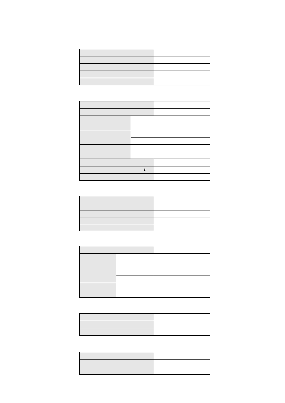
SPECIFICATIONS
TYPE
INDOOR UNIT
OUTDOOR UNIT
COOLING CAPACITY
HEATING CAPACITY
ELECTRICAL DATA
POWER SOURCE
FREQUENCY
RUNNING CURRENT (A)
INPUT WATTS (kW)
E.E.R. (kW/kW)
STARTING CURRENT
MOISTURE REMOVAL
AIR CIRCULATION-Hi
(kW)
(kW)
(V)
(Hz)
COOLING
HEATING
COOLING
HEATING
COOLING
HEATING
(A)
( /hr)
3
(m
/hr)
COOL & HEAT
AUH18LBAB
AOH18LMAKL
4.70
4.80
230
50
7.2
7.5
1.65
1.71
2.85
2.81
10
2.0
620
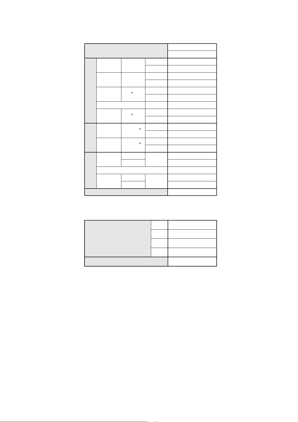
COMPRESSOR
TYPE
DISCRIMINATION
POWER SOURCE
REFRIGERANT (R410A)
FAN MOTOR
POWER SOURCE
INDOOR UNIT
OUTDOOR UNIT
DIMENSIONS
INDOOR UNIT
OUTDOOR UNIT
GRILLE
DISCRIMINATION
HI-SPEED
MED-SPEED
LO-SPEED
DISCRIMINATION
HI / LO
H x W x D
H x W x D
H x W x D
(r.p.m.) 800
(r.p.m.)
(r.p.m.) 600
(r.p.m.)
Hermetic type, 4 poles,
DC motor, twin Rotary
TNB220FPCM
230V 50Hz
(g)
(V) 230
MFA-18GTBT
MFB-24JTAT
(mm)
(mm)
(mm)
235 x 580 x 580 +70
650 x 830 x 320
35 x 650 x 650
1,500
700
780 / 400
2005.01.12
WEIGHT
INDOOR UNIT
OUTDOOR UNIT
GRILLE
NET / GROSS
NET / GROSS
NET / GROSS
(kg)
(kg)
(kg)
18 / 23
54 / 58
2.2 / 4.3
1
Page 3
MODELS
DISCHARGE
PRESSURE
SUCTION
PRESSURE
DISCHARGE
TEMP.
REFRIG. PIPE LENGTH
DISCHARGE
REFRIGERANT CIRCUITCONDITIONPIPING
AIR TEMP.
INDOOR
ENTERING
AIR TEMP.
OUTDOOR
ENTERING
AIR TEMP.
PIPE DIA.
SIZE
CONNECTION METHOD Flare
BETWEEN
REFRIGERANT TYPE
MPa
MPa
C
C
DB/WB
DB/WB
LIQUID
GAS 12.7
HEIGHT
PIPE LENGTH
COOLING 2.72
HEATING 3.36
COOLING 0.85
HEATING 0.80
COOLING 71
HEATING 84
m
COOLING 10
HEATING 47
COOLING
C
HEATING
COOLING
C
HEATING
mm
m
AUH18LBAB
AOH18LMAKL
7.5
27.0 / 19.0
20.0 /
––
35.0 / 24.0
7.0 / 6.0
6.35
Max. 15
Max. 25
R410A
REFRIGERANT CHARGE ( R410A )
PIPE LENGTH 10 m
15 m
FULL CHARGE AMOUNT
( g )
ADDITIONAL REFRIGERRANT
20 m
25 m
( g / m )
1,500
1,600
1,700
1,800
20
2005.01.12
2
Page 4
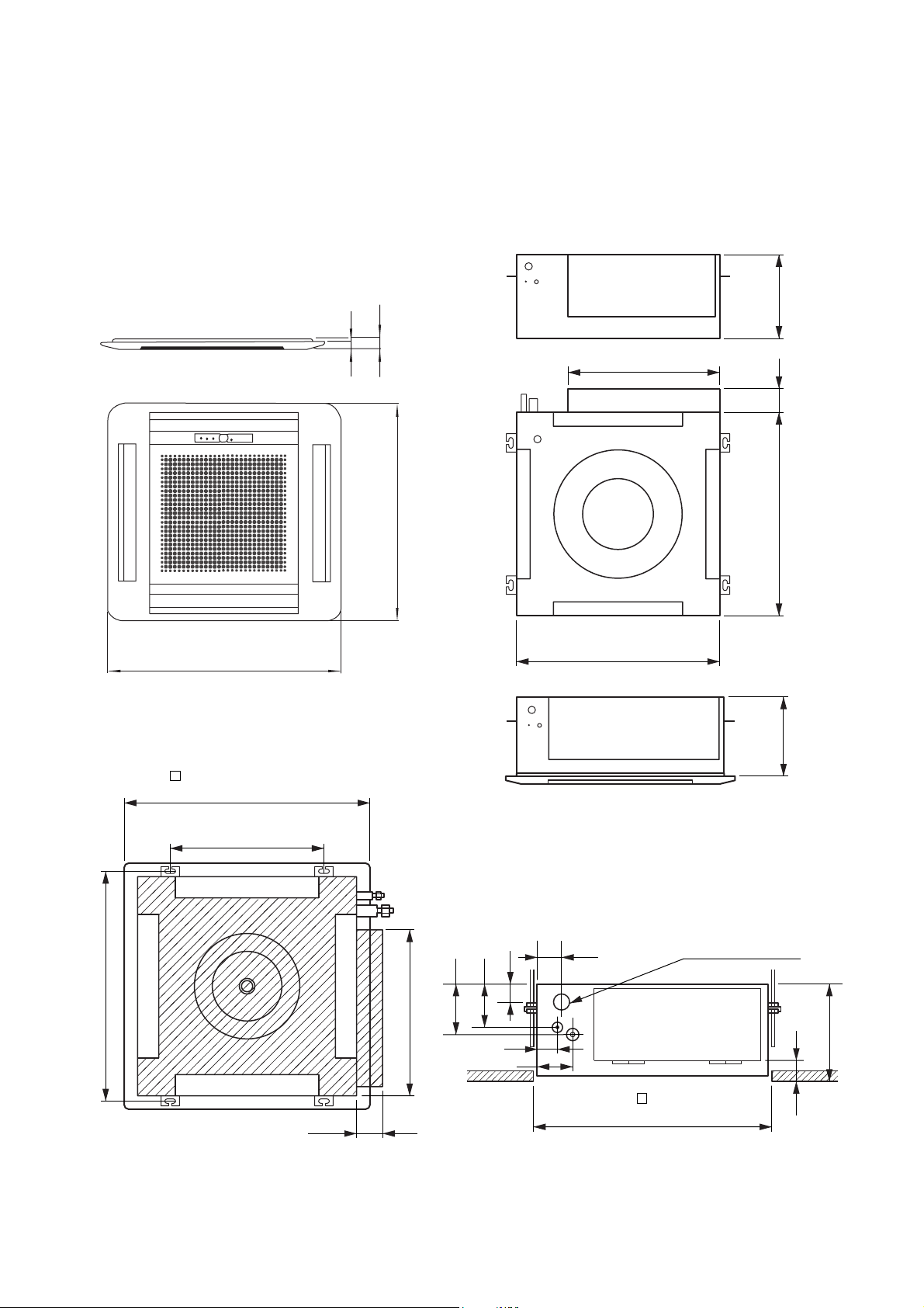
235
66
250
440
580
( 650) (Grille measurement)
650
(Hanging bolt position)
400
(Hanging bolt position)
606
580 66
440
600
(Ceiling opening measurement)
250
60
86
Drain pipe (I.D. 32)
54
46
131
111
47
INDOOR UNIT
OUTLINE AND DIMENSIONS
(unit : mm)
20
35
650
650
32005.02.07
Page 5
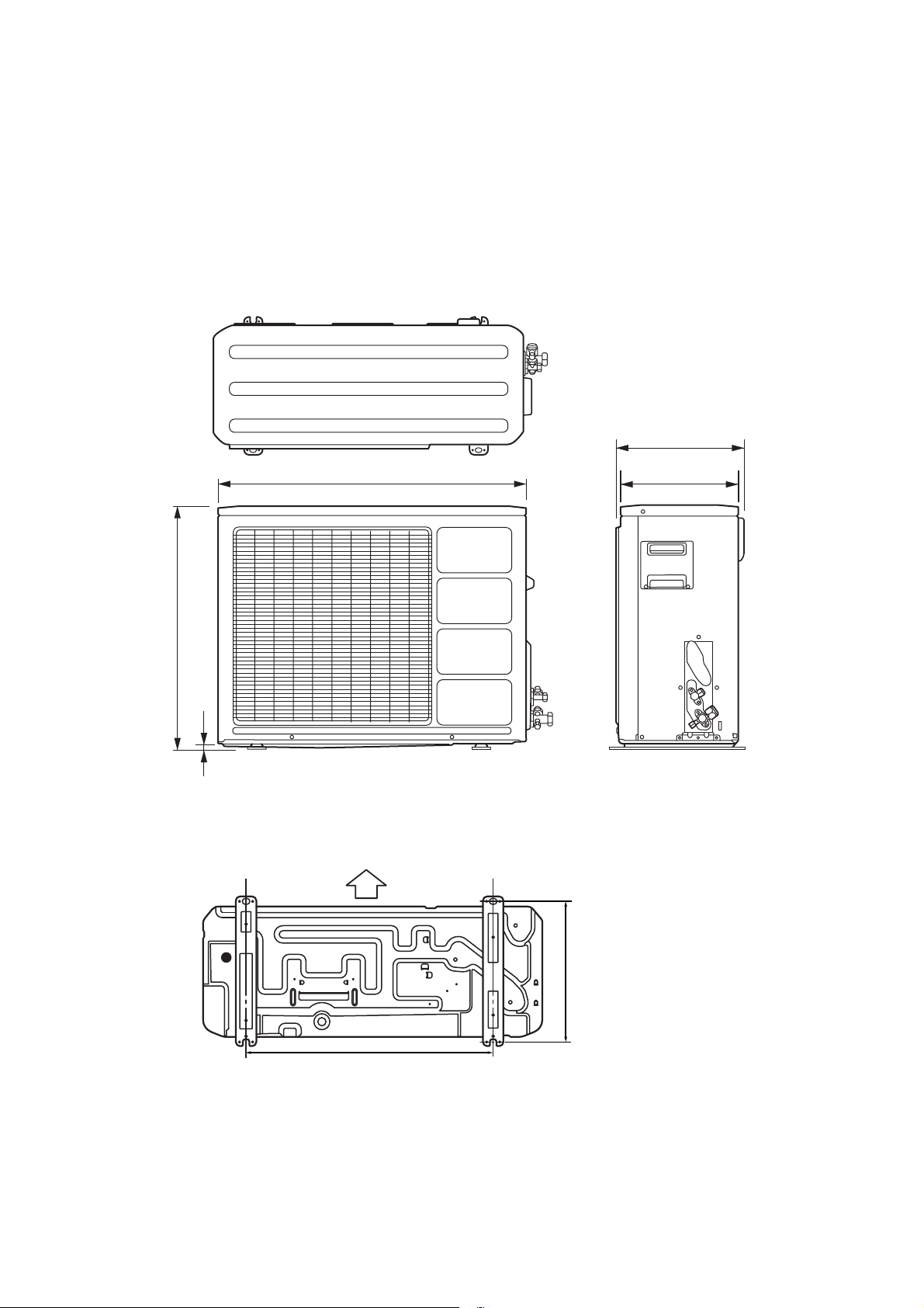
OUTDOOR UNIT
Unit : mm
350
830
650
12
Air flow
Bottom
320
603
343
42004.11.01
Page 6
Model : AUH18LBAB
CIRCUIT DIAGRAM
Thermistor
(pipe temp.)
Stepping
Motor
Fan Motor
Fan Motor
Capacitor
Thermistor
(room temp.)
Float Switch
Controller PCB
Filter Board
Drain Pump Motor
to outdoor unit
Terminal
2005.02.07
5
Page 7

Model : AOH18LMAKL
2005.01.12
6
Page 8

REFRIGERANT SYSTEM DIAGRAM
Models : AUH18LBAB / AOH18LMAKL
OUTDOOR UNIT
HEAT EXCHANGER
HEAT COOL
COMPRESSOR
4-WAY VALVE
MUFFLER
ACCUMULATOR
3-WAY
VALVE
CAPILLARY
TUBE
EXPANSION
VALVE
STRAINER
2-WAY
VALVE
2005.02.28
INDOOR UNIT
HEAT EXCHANGER
7
Page 9

ERROR CONTENTS
Operation can be checked by lighting and flashing of the grille
display section OPERATION and TIMER lamps.
Perform judgment in accordance with the following.
SWING TIMER OPERATION
SWING LAMP
(Orange)
TIMER LAMP
(Green)
MANUAL
AUTO
OPERATION LAMP
(Red)
TEST RUNNING
When the air conditioner is run by pressing the remote control
unit test run button, the OPERATION and TIMER lamps flash
slowly at the same time.
CHECK ITEMS
1. INDOOR UNIT
(1)
Is operation of each button on the remote control unit
normal?
(2)
Does each lamp light normally?
(3)
Do not air flow direction louvers operate normally?
(4)
Is the drain normal?
(5)
Is there any abnormal noise and vibration during operation?
2. OUTDOOR UNIT
(1)
Is there any abnormal noise and vibration during operation?
(2)
Will noise, wind or drain water from the unit disturb the
neighbors?
(3)
Is there any gas leakage?
Do not operate the air conditioner in the test running state
for a long time.
INDOOR UNIT OUTDOOR UNIT
OPERATION
lamp
Blinks
Pulses
4 times
Pulses
6 times
Pulses
2 times
Pulses
3 times
Error display
TIMER
lamp
Blinks Goes off
Blinks Goes off
Blinks Goes off
Blinks
Blinks
SWING
lamp
Goes off
Blinks
Goes off
Blinks
Error contents
Model information abnormal
(permanent type)
Drain abnormal (permanent type)
Indoor fan abnormal
Room air temperature thermistor
open circuit
Room air temperature thermistor
short circuit
Piping thermistor open circuit
Piping thermistor short circuit
Serial signal error
Discharge pipe thermistor error
Heat exchanger thermistor error
Outdoor temperature thermistor error
2 - way valve thermistor A, B error
3 - way valve thermistor A, B error
Compressor thermistor error
Pressure switch error
Indoor unit communication error
Current trip error
CT error
Compressor position detection error
Compressor starting error
Timer error
Error contents LED (RED)
1 time blink
2 times blink
3 times blink
4 times blink
5 times blink
6 times blink
7 times blink
8 times blink
9 times blink
10 times blink
11 times blink
12 times blink
13 times blink
14 times blink
2004.11.01
8
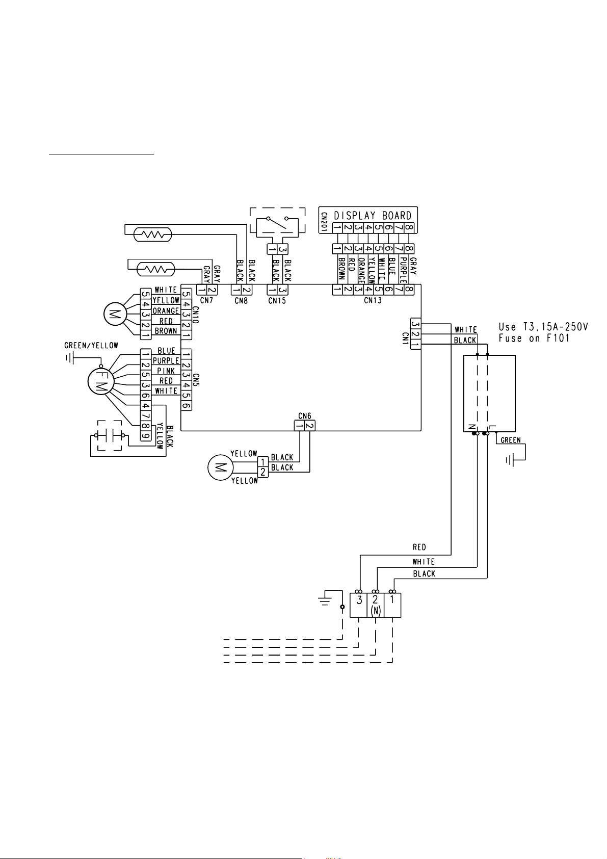
Page 10

INDOOR PCB CIRCUIT DIAGRAM
CONTROLLER PCB ASSEMBLY ( MAIN PCB )
Model : AUH18LBAB
K01AL-040EHSE-C1
2005.02.07
230 V
50HZ
9
Page 11

OUTDOOR PCB CIRCUIT DIAGRAM
Model : AOH18LMAKL
POWER SOURCE
220 / 240V
50Hz
TO
INDOOR UNIT-A
FAN CAPACITOR
FAN MOTOR
F M 1
4-WAY VALVE
PRESSURE SWITCH
COMP. THERMOSTAT
EXPANSION VALVE-A
M
HEATSINK
TEMP. TH.
DISCHARGED
TEMP. TH.
PIPE
TEMP. TH.
OUTDOOR
TEMP. TH.
EMI FILTER
RFC-8
F201 TLC
1T
25A - 250V
L
N
L
N
3
UL1015
AWG20 x 4
UL1015
AWG20
C200
450V
3.5uF
BLACK
UL1015
AWG20
BLACK
CN11 B4P7-VH-B
CN30 179844-1 WHITE
CN37 B2B-XARK-1-A RED
CN38 B2B-XAMK-1-A GREEN
CN27 B6B-XARK-1-A RED
CN25 B2B-XAKK-1-A BLACK
BROWN
BROWN
CN21 B2B-XH-AM YELLOW
BROWN
BROWN
CN22 B2B-XH-AM RED
BLACK
BLACK
CN23 B2B-XAEK-1-A BLUE
BLUE
BLUE
WHITE
BLACK
WHITE
BLACK
WHITE
RED
BLUE
BLACK
BLACK
RED
RED
BROWN
BROWN
RED
BROWN
BLUE
ORANGE
YELLOW
WHITE
B
UL1015
AWG16
GREEN
EARTH
RED
UL1015
AWG14
BLACK
W1
BLACK
B
W4
BLACK
W2
BLACK
B
W5
BLACK
B
W3
B
W8
W103
BLACK
W102 B
4
3
2
1
CR5
2
RE1202
1
1
2
1
2
12V
1
2
3
4
5
6
1
2
1
2
1
2
1
2
VA101
470V
<TNR>
VA102
470V
<TNR>
SA100
RA-302M
GREEN
RED
B
BLACK
5V
R91
L202
BL02Rn1
L201
BL02Rn1
SERIAL A
CR1
RE1202
K11
G5SB-14
3
4
5
R90
2.2K x 2
<1/10W>
C70C71
0.1 <F> x 2
5V
R63 6.65K
<1/10W>
(1%)
R65 56K
<1/10W>
(1%)
R67 38.3K
<1/10W>
(1%)
L1
RCV2515-010PF05
C101
1.0
<LE>
K13
2
2 3
12V
4
+
1
G5NB-1A
3
12V
1
K17
G5NB-1A
1.0K <1/10W> x 2
R93
R92
C73
0.01 <F> x 2
1
4
12V
1
2
4
C72
R62 10K
<1/10W>
R64 10K
<1/10W>
R66 10K
<1/10W>
2
C104
0.033
<YE>
C105
0.033
<YE>
3
PFC5000-0502
x 2
FH1
F4
250V - 5A
<BET>
8
12V
2.2K <1/10W>
C37
0.1
<F>
C38
0.1
<F>
C39
0.1
<F>
C43
0
C44
0
C45
0
C46
0
R43
C106
1.0
<LE>
FH2
1418
7
D28
SLR-332
<RED>
16
12
13
TM100
HY I C1
HU2001
10
6
2
O1
7
O2
9
O3
O4
4
GND1
5
GND2
GND3
GND4
I C4
TD62064
L2
N200500K
54
1
3
5
5V
I C3-5 M54523
I C3-6 M54523
I C3-4 M54523
I C3-2 M54523
I C3-1 M54523
I C3-7 M54523
I C3-3 M54523
3
I 1
6
I 2
11
I 3
14
I 4
12V
1
COM1
8
COM2
10
NC1
15
NC2
R47
2.94K
<1/10W>
(1%)
R45 10K
<1/10W>
R44 6.65K
<1/10W>
(1%)
C107
3.3
<LE>
CT1
CT-1B
R60 1.0K
<1/10W> (1%)
4 3 2
1
3
4
5
2 1
12
11
13
15
16
10
14
R97
R96
R95
R94
1.5K <1/10W> x 4
5V
R46
2.87K
<1/10W>
(1%)
I C14-1
uPC393
C74
0.1
<F>
R51 4.7K
5V
C75
0.1
<F>
2
3
5V
5V
<1/10W>
-
+
5V
1
2
C60
220/16V
<PJ>
5V
R50
10K
<1/10W>
R52 1.0K
<1/10W>
R53
10K
<1/10W>
5
6
4
2
1
7
3
5V
1
C76
0.1
<F>
R11
10K
<1/10W>
L4
RCV2515-010PF05
1 2
D60
DAN217U
3
+
VR1
B2K
R61 3.74K
<1/10W> (1%)
R55 1.0K
<1/10W>
R56 27K <1/10W>
3
Q51
1
2SC2412K
2
<BQ>
C51
0.022 <F>
5V
R49
10K
<1/10W>
R42 1.0K
<1/10W>
C77
0.1
<F>
C111
1.0
<LE>
34
R68 22K
<1/10W>
C40
0.1
<F>
C53
0.022
<F>
C64
0.1
<F>
12V
4
1
K101
DW12D1
R404
510
<1/10W>
MB90462PFM-G
-167-BN0-E1
1
2
R200
ZPR0RCH400
3
2
C114
1.0 <LE>
R437 270
<1/10W> (1%)
R438 270
<1/10W> (1%)
5V
2
I C 1
VCC
17
AVCC
P62
16
2
P00
P46
P01
P12
35
P50
3
P17
59
P13
P37
58
P14
P36
60
P40
P15
21
MD2
P16
AVR
P11
34
P24
P26
47
P25
27
P02
28
P03
P30
29
P31
P04
30
P32
P05
P33
31
P06
32
P34
P07
P35
P10
33
P60
57
C
P61
41
P20
42
P21
MD0
P22
43
MD1
44
P44
P23
P43
P57
10
P42
P56
9
P41
8
P55
P45
P54
7
5
RSTX
P52
6
P27
P53
AGND
4
P51
22
GND
X0
23
X1
GND
3
X1
8.00MHz
<EF0EC>
CONTROLLER PCB ASSEMBLY
K03AV-0401HUE-C1
CHOKE COIL
L=0.3MH 30A
UL1015
W10
RED
AWG14
W11
BLACK
1
2
3
4
C95
100P
<CH>
I C201
BR93LC46
1
CS
VCC
2
SK
3
D I
6
NC
GND
JM207
R78
R79
C16
+
4.7/50V
<PS>
2
SUBNCVCC
1
I C6
BD4742G
RED
BLACK
UL1015
AWG14
10K
<1/10W>
x 2
8
4
DO
7
NC
5
R77
R73 82K
<1/10W>
VOUT
GND
BROWN
RED
ORANGE
YELLOW
UL1007
AWG24
035
0.01
<F>
R76
5
4
3
+
-
2
3
D101
D25XB60
1
2
3
I C402
PS2561L-1-V
Q401
1
DTC114EKA
0.1 <F> x 2
C19 C18
56P63
11
R608 10K
25
<1/10W>
26
40
36
37
38
39
12
45
46
50
51
52
53
54
55
14
15
18
20
64
63
62
61
1
19
48
13
24
49
+
-
0.1
<HCP>
4
C115
1
18V
C415
0.01
<F>
A
CN407
C413
B4B-XASK
0.01
-1-A WHITE
<F>
A
ACTPM CONTROL
A
18V
4
3
5V
+
C20 <PS>
4.7/50V
5V
U
X
V
Y
W
Z
5V
R19 10K
<1/10W>
R72 1.0K
<1/10W>
C17
0.01
<F>
L1
I C414
SACT32010A
ACTPM
R407
036
0.01
<F>
R113
1.0K
<1/10W>
R114 27K
<1/10W>
5V
C91
0.01
<F>
R205 10K
<1/10W>
5V
R74
R75
5V
TERMINAL 2P
L2
5V
4
R403
I C401
PS2561L-1-V
4
3
I C404
PS2561L-1-V
5V
Q91
3
2
10K
<1/10W> x 6
EMI FILTER
TFC-25
-15-12
2T
P
N1
18V
5V
2SC2412K
<BQ>
1
560 <1/10W>
x 6
C204
1200 450V
WHT
PURPLE
UL1015 AWG14
I C400-1
uPC393
R436
1
3.3K
<1/4W>
23
18V
R442
1
3.3K
2
<1/4W>
R103 4.7K
<1/10W>
8
6
5
I C13
PS8602
I C301 - I C306
PS2561L-1-V x 6
R605 22K
EMI FILTER
RFC-8
1T
YEL
+
BLUE
C409
10/
25V
<PS>
+
D402
18V
RD3.3ES <B2>
8
C411
2
1
-
0.01 <F>
3
+
I C400-2
uPC393
7
I C11-2
uPC393
R310 - R315
100 <1/10W> x 6
R316 - R321
100 <1/10W> x 6
R85
R84
R83
R82
R81
R80
6
-
5
+
A
C412
0.1
<F>
15V
R102
1.6K
<1/4W>
2
3
I C11-1
uPC393
7
5V
1
2
1
2
1
1
2
1
2
1
2
1.0K
<1/10W> x 2
C414
0.01
<F>
1
6
-
5
+
2
A
A
10K <1/10W> x 5
R21
R604
<1/10W>
R20
10K
<1/10W>
-
+
TM104
TM105
18V
A
R435
R441
C87
470P
<CH>
2
3
5V-2
4
3
4
3
4
3
4
3
4
3
4
3
R322
R603
R201 220K
<2W>
A
R402 S3.3K
<1/4W>
R406
2.87K
R401
2.94K
A
<1/10W>
(1%) x 2
C89
470P
<CH>
R323
R324
330 <1/10W> x 6A
5V
R602
R601
R400
R440
R325
180K <RN - 1/2W>
15V
5V
C116
0.1 <HCP>
(1%) x 2
C88
0.1
<F>
A
R326
R327
1
2
3
4
5
6
7
8
9
10
R140
1.2
<1/2W>
1
1
1
1
1
1
BARE WIRE
SN-PLATED
Q1
2SC4236
DAN217U x 2
D81 D82
2
FH3 PFC5000-0502
F2 250V
<BET> 3.15A
L100
DIA 0.65MM
3
FH4 PFC5000-0502
R1
220K
<2W>
R3 100
<1W>
2
1
3
D10
RD5.6ES
D1
D1FL20U
112
3
R105 2.49K
<1/10W> (1%)
R108 2.87K
<1/10W>
(1%)
R328 - R333
5V-2
1.0K <1/10W> x 6
3
2
3
2
3
2
3
2
3
2
3
Q301
2
Q302
Q303
Q304
Q305
Q306
2SC2412K
<BQ> x 6
CN601
B10B-PASK-1 WHITE
TAUX
TTXD
TRXD
TAUX3
TCK
/ TRES
/ T I CS
FLASH
TMODE
R2 1.0K
<RS - 3W>
C1 220P
<BN>
C2 0.047
<ECQB>
D2
D1FL20U
C3
<B2>
100/16V
<PJ>
R4 330
<1/4W>
R104
195K x 6 (1%)
<RN - 1/2W>
R111
R112
R106
R110
R87 2.94K
<1/10W>
(1%)
R107 680
<1/10W>
(1%)
A
R360
39
<1/2W>
A
C316
C314
C315
2200P <B> x 6
C4
T1
JPZ-200
16
15
13
12
10
9
D100
D1FL20U
+
C7
220/
35V
<PJ>
195K x 6 (1%)
R86
<RN - 1/2W>
15V
+
1
2
3
6
7
8
I C101
TA7805
1 3
I
D8
D1FL20U
D7
D1FL20U
O
G
+
2
C10
100/16V <PS>
R5 10K
<1/10W>
D401
D1FL20U
C406
220/50V
<PJ>
5V-2
C11
0.1
<F>
A
470/25V
<PJ>
+
C5
220/16V
<PJ>
1
+
+
1
G
2
I C407
uPC24M18
I C8
TA7805
I
G
2
33I
O
12V
5V
O
C6
+
100/16V
<PS>
18V
C418
+
10/35V
<PS>
A
R89
R88
5V
I C307
R33
PS2561L-1-V
10K
R40 1.0K
<1/10W>
<1/10W>
C34
15V
330K <1/10W> x 3
U1JU44 x 3
0.1 <F> x 3
C33
0.01
0.01
<F>
<F>
47/35V <PJ> x 3
+
R361
D301
C323
C305C304
+
C322
D302
R363
+
C321
R362
D303
15V
A
15V
A
15V
C312
C313
C311
A
C324 - C326
0.1 <F> x 3
I C310
C303
PS21246
1
2
3
4
5
6
7
8
9
10
11
12
13
UP
VP I
VUFB
VUFS
VP
VP I
VVFB
VVFS
WP
VP I
VPC
VWFB
VWFS
A
R303
4.7K
<1/10W>
C332
0.1
14
VN I
<F>
VNC
15
16
C IN
17
CFO
18
FO
19
UN
C327
20
VN
0.022
21
WN
<F>
P
22
23
U
24
V
25
W
26
N
15V
4
3
5V-2
R302 1.0K
A
<1/10W>
A
C328
2200P
<B>
A
5V-2
1
2
R301
R304
560
<1/10W>
0.02
<5W>
x 2
TM303
W
BLACK
R305
A
TM304
TM305
V
U
RED
WHITE
C M
2005.01.11
10
Page 12

Model : AUH18LBAB
484
DISASSEMBLY ILLUSTRATION
462
464
495
67
187
117-3
467
244
287
465
313
797
411
465
479
478
138
395
338
146
164
411
652-1
965
184-1
235
474
470
411
834
798
484
127
836
482
196
160
2005.01.12
240
743
476-3
475
476-2
476-1
469
468
399
11
457
488
430
301
234
Page 13

Model : AUH18LBAB
34
381
628
514
629
824-3
875
236
815
989-1
381
381
628
381
185
287
223
989-2
2005.01.12
12
Page 14

Model : UTG-UDGD-W
417
165
694
691
690
226
196
692
876-2
705
763
692
416
416
417
392
690
385
705
691
690
758
710
777
691
690
392
692
700
776
711-2
93
2005.01.12
776
711-1
13
Page 15

Model : AOH18LMAKL
470
14
7
734
2005.01.12
64
4-1
4
5
2
14
Page 16

Model : AOH18LMAKL
45-3
41
39
33
31
29
16
45-2
45-1
411
109
754
334
344
17
349
26-2
45-4
26-1
55
46
348
108
335
361
12
343
346
85
273
13-3
345
13-2
2005.01.12
15
Page 17

INDOOR UNIT
PARTS LIST
Ref.
No.
34 Capacitor (Fan Motor) 9703306044
67 Rubber
117-3 Special Washer M6
127 Drain Hose
138 Separate Wall-A
146 Evaporator Assy-IN
160 Drain Pan
164 Fan Motor Assy-IN
184-1 Thermo. Spring-A
185 Rubber Bushing
187 Clamp No. 1219
196 Clamp SKB-150
223 Control Box 9359661016
234 Thermistor Assy-Room
235 Thermistor Assy-Pipe
236 Controller PCB Assy
240 Remote Control Unit
244 Pipe Cover
287 Cap (Power)
301 Clamp NK-2N
313 Hooking Wire
338 Motor Fixture 9359656005
381 Locking Spacer
395 Supporter (Eva. ) 9373179016
399 Air Duct 9359660002
411 Supporter-A 9359655008
430 Clamp NK-7N 313095365602
457 Drain Pan Support 9359652007
462 Top Cover Plate 9359642015
464 Body-A
Description
Part No.
AUH18LBAB
9361279001
313306391007
9359659013
9359647003
9373214014
9359651000
9601040057
313728262708
313005066051
313361271706
313035356905
9703299032
9703297014
9704557797
9371190037
9359646006
9352173011
313985355201
9359983002
313209391506
9359643005
Ref.
Ord.
No.
Q'ty
465 Body-B 9359645009
467 Drain Port 313005415658
468 Special Nut-A (Large) 313005446653
469 Special Nut-B (Small) 313005446759
470 Separate Wall-B 9359648000
474 Turbo Fan 9359658009
475 Turbo Fan Rubber 9366013006
476-1 Special Nut M8 313005360755
476-2 Special Washer 301801185049
476-3 Special Washer 9359954002
478 Sensor M. Bracket 9359654001
479 Float Switch 313005416154
482 Pump Unit 9359974000
484 Hanger Metal 9359644002
488 Drain Pan Plug 9359653004
495 Clamp No. 2U46 9352715006
514 Control Box Cover 9359662006
628 Locking Spacer-B 313005446558
629 EMI Filter 0400197119
652-1 Therm. Holder Pipe 313806262805
743
797 Separate Wall-C 9359649007
798 Pump Hook Bracket 9359650003
815 Terminal-3P 9900203016
824-3 Fuse 0600222512
834 Wire Cover 9359878001
836 Cushion-B (For Pump) 9356084016
875 Filter PCB Assy 9704561213
965 Flare Nut-B 9351062019
989-1 Cord Clamp-A 9359822011
Description
Remote Control Holder Case
Part No.
AUH18LBAB
9305642014
Ord.
Q'ty
GRILLE ASSY (UTG-UDGD-W)
Ref.
No.
93 Filter 9359632009
165 Motor Cover 9359623014
196 Clamp SKB-150 313035356905
226 Motor Gear 9359629009
385 Indicator PCB Assy 9702224011
416 Insulation (Panel)-A 9359620006
417 Insulation (Panel)-B 9359621003
690 Joint-A
691 Joint-B
692 Joint Shaft 9359625001
694 Cam Gear 9359628002
Description
Part No.
9359622017392 Cover-A
9359626008
9359627005
989-2 Cord Clamp-B 9359823018
Ord.
Ref.
Q'ty
No.
705 Louver 9359624011
710 Intake Grille 9370126006
711-1 Filter Clamp-A 9359634003
711-2 Filter Clamp-B 9359635000
758 Decoration Plate
763 Receiver Cover 9359630005
776 Grille Stopper 9359633013
777 Grille Hook 9359761006
876-2 Step Motor-V 9360307019
Description
(UTG-UDGD-W)
Part No.
9359619017700 Panel
9360039026
Ord.
Q'ty
2005.02.07
16
When you order parts, please make a photocopy of this page
and fill the number of the parts in the "Order" column.
Page 18

OUTDOOR UNIT
Ref.
No.
2 Fan Guard 9371187013
4 Emblem 9372171011
5 Front Panel Painted
7 Connecteor Cover (Cabinet)
12 Base Assy, Painted 9371920078
13-2 2-Way Valve 9372204054
13-3 3-Way Valve
14 Valve Cover 9372796016
15 Condenser Sub Assy
16 Condenser Assy 9372181096
17 Thermister Holder Pipe 313714262805
26-1 Compressor Cover A 9373730019
26-2 Compressor Cover B 9373730026
29 Separate Wall 9372795019
31 PWB Assy 9705285033
33 Control Cover 9372792018
34 Capacitor, Plastic 9704305077
39 Propeller Fan Assy 9366378013
41 Motor Induct 9601671046
45-1 Motor Bracket 9371929019
Description
Part No.
AOH18LMAKL
9371924014
9366398004
9372205051
9372313183
Ord.
Q'ty
Ref.
No.
187 Clip (Cable) 9352715006
199 Br Sheet 9363708042
218-3 Relay 9900117016
273 Strainer Assy 9366602019
334 Accumlator 9368391003
335 Accumlator Holder Rubber 9354022010
343 Solenoid 9900165079
344 4-Way Valve 9900163013
348 Pressur Switch Assy 9373729044
349 Capirarry Assy 9373729433
361 Accum Support Assy 9372252017
411 Gasket 9373266013
527 Protective Net 9371934013
734 Top Plate 9371925011
754 Washer (Rubber) 9358078006
--- Compressor pressure switch 9900186012
--- Compressor thermal switch 9373263012
--- Thermistor discharge 9704219039
--- Heat exchanger thermistor 9704220059
--- Thermistor outdoor 9703516047
Description
Part No.
AOH18LMAKL
Ord.
Q'ty
45-2 Motor Bracket-Top 9371931012
45-3 Motor Bracket-Ctr 9371930015
45-4 Motor Bracket-Bottom 9371932019
46 Compressor Assy 9373262015
55 Special Nut M8 9355091008
64 Side Panel L Ptd 9371926018
69-3 Bolt, hex, Socket 301210060360
85 Valve Plate Ptd 9371928036
108 Rubber Seat (Comp) 9358080009
109 Terminal Cover (Comp) 9373264019
Inverter Assy
Ref.
No.
31 Controller PCB Assy 9705285033
--- ACTPM 9703457012
--- Capacitor, Elec 9705387010
34 Capacitor, Plastic 9704305077
--- Fuse 0600086039
--- Terminal 5P 9900203023
--- Fuse Holder 0501454012
--- Terminal 2P 9701971015
Description
Part No.
--- Thermistor heat sink 9900195014
Ord.
Q'ty
2005.01.12
17
When you order parts, please make a photocopy of this page
and fill the number of the parts in the "Order" column.
Page 19

STANDARD ACCESSORIES
INDOOR UNIT ACCESSORIES
Name and Shape Application Part No.
Coupler heat insulation For indoor side
pipe joint
9350716029
9352766015
Special nut A
(large flange)
Special nut B
(small flange)
Template For ceiling hole cutting
Remote control unit Use for air conditioner
Battery
(penlight)
Remote control unit holder For mounting the remote
Tapping screw For remote control unit
( 3 x 12)
For installing
indoor unit
For installing
indoor unit
operation
For remote control unit
control unit
holder installation
313005446653
313005446759
9360256003
9371190037
0600185534
9305642014
301141533125
OUTDOOR UNIT ACCESSORIES
Name and Shape
Drain Pipe
Drain Cap
Application
For outdoor unit drain
piping work
[Heat & Cool (Reverse
cycle) model only]
GRILLE ASSY ACCESSORIES
Name and Shape
Bolt For opening the
Washer For mounting grille
Blower cover insulation For discharged air
Application
refrigerant valve on the
outdoor unit
Part No.
9303029015
313166024302
Part No.
0700139116
301801155020
9360047007
2005.01.12
18
Page 20

0411G2689
 Loading...