

Page 1
R410A
7 . CASSETTE TYPE :
AU 12LBAB, AU 14LBAB
D2D_AU023E/01
2006.03.20
Page 2
7-1. FEATURE
MODELS :
AU 12LBAB / AO 12LMAKL
AU 14LBAB / AO 14LMAKL
FEATURES
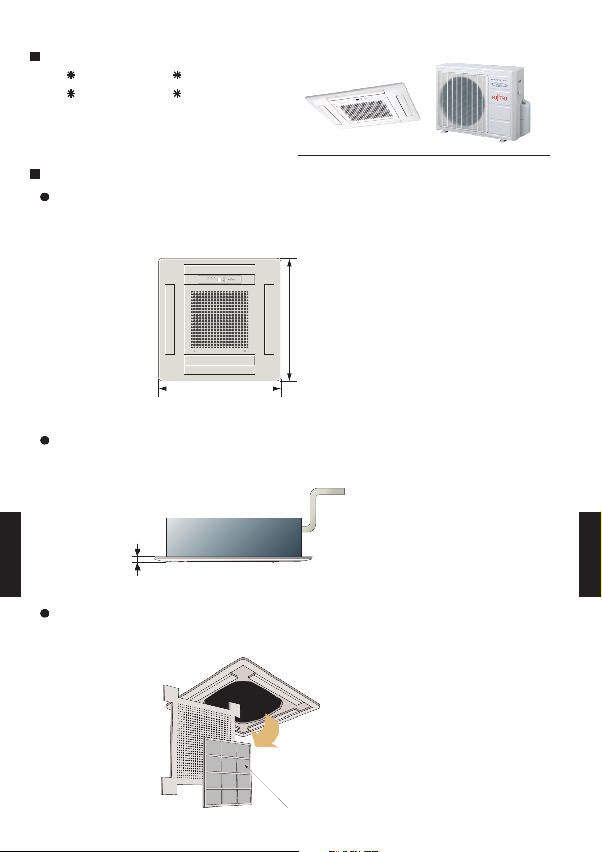
Compact size
Compact grille fits European ceiling panel (650 x 650 mm).
Punch Hall grille
650
650
(unit: mm)
Slim intake grille
Slim type intake grille can fit the ceiling after installation.
20
CASSETTE TYPE
AU12-14L
(unit: mm)
CASSETTE TYPE
AU12-14L
Detachable,washable filter and intake grille.
Intake grille and air filter can be removed easily and cleaned.
Long-life filter
- (07 - 01) -
Page 3
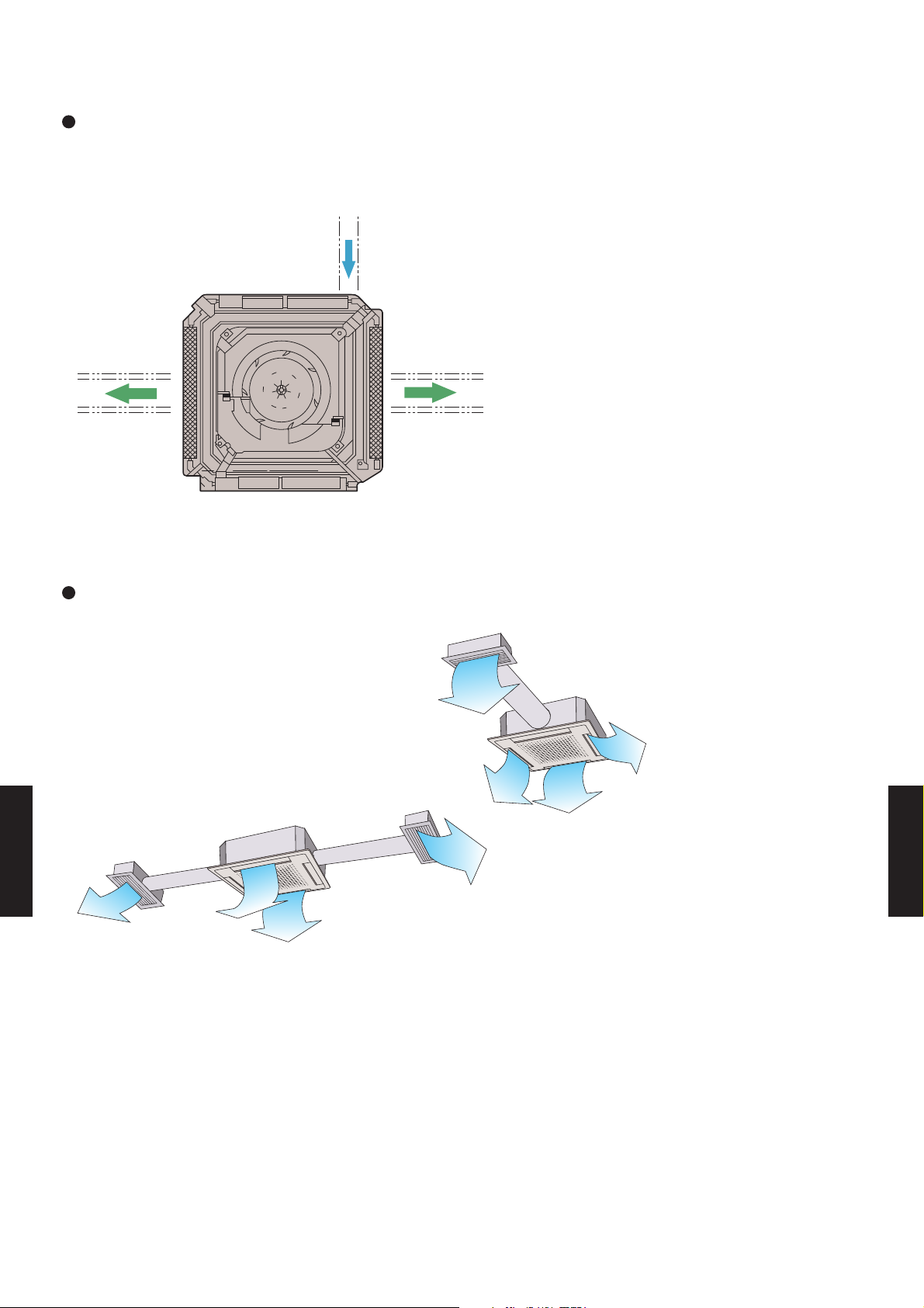
Duct connection hole opening
Fresh air can be introduced through this opening.
Fresh air
Distribution
duct
Distribution
duct
Conditioned air can be distributed by means of a distribution duct.
One-way
Two-way
CASSETTE TYPE
AU12-14L
- (07 - 02) -
CASSETTE TYPE
AU12-14L
Page 4
7-2.
REMOTE CONTROLLER
7-2-1. WIRELESS REMOTE CONTROLLER
FEATURES
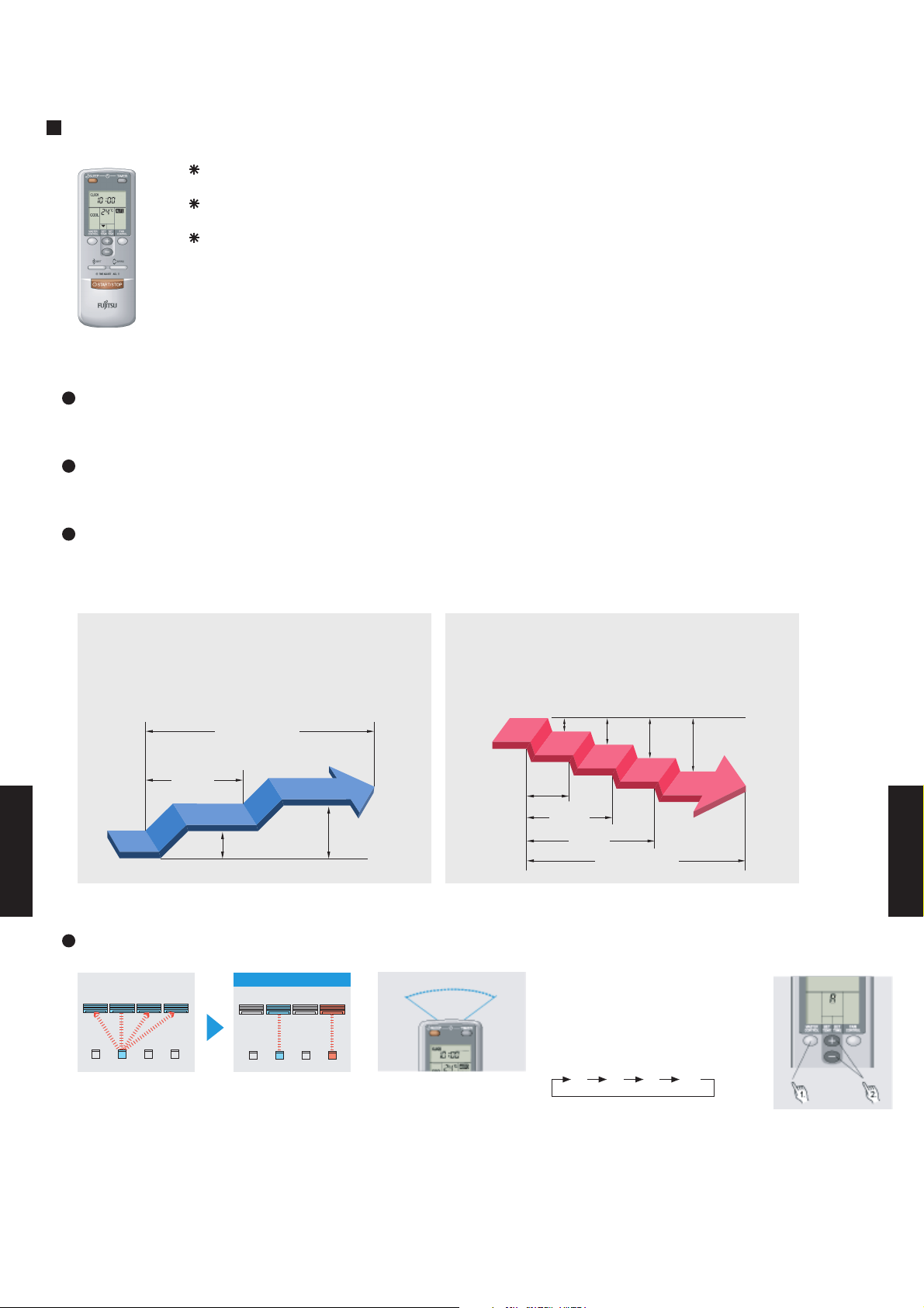
Four kinds of timer setup (ON / OFF / PROGRAM / SLEEP) are possible.
Four kinds of timers. Easy operation.
Easy to change transmission code (4 patterns) by button operation.
Built-in timers
Select from four different timer programs (On/Off/Program/Sleep).
Program timer
The program timer operates the ON and OFF timer once within a 24 hour period.
Sleep timer
The sleep timer function automatically corrects the temperature thermostat setting according to the
time setting to prevent excessive cooling and heating while sleeping.
Cooling operation/dry operation
When the sleep timer is set, the set temperature
automatically rises 1 °C every hour. The set
temperature can rise up to a maximum of 2 °C.
Timer setting
60min.
1 °C
CASSETTE TYPE
AU12-14L
2 °C
Heating operation
When the sleep timer is set, the set temperature
automatically drops 1 °C every 30 minutes. The
set temperature can drop to a maximum of 4 °C.
1 °C
2 °C
3 °C
4 °C
30min.
60min.
90min.
Timer setting
CASSETTE TYPE
AU12-14L
Simultaneously operation
After code change
Mixed-up
• Code selector switch eliminates unit
being wrongly switched.
(Up to 4 codes can be set.)
A B C D
A B
C
D
•Wide and precise
transmitting range.
1. Press the MASTER CONTROL
button for more than five seconds
to start the code change.
2. Press the (+) or (-) button to
select the desired code.
A B C D
3. Press the MASTER CONTROL
button again to end the code
change.
- (07 - 03) -
Page 5
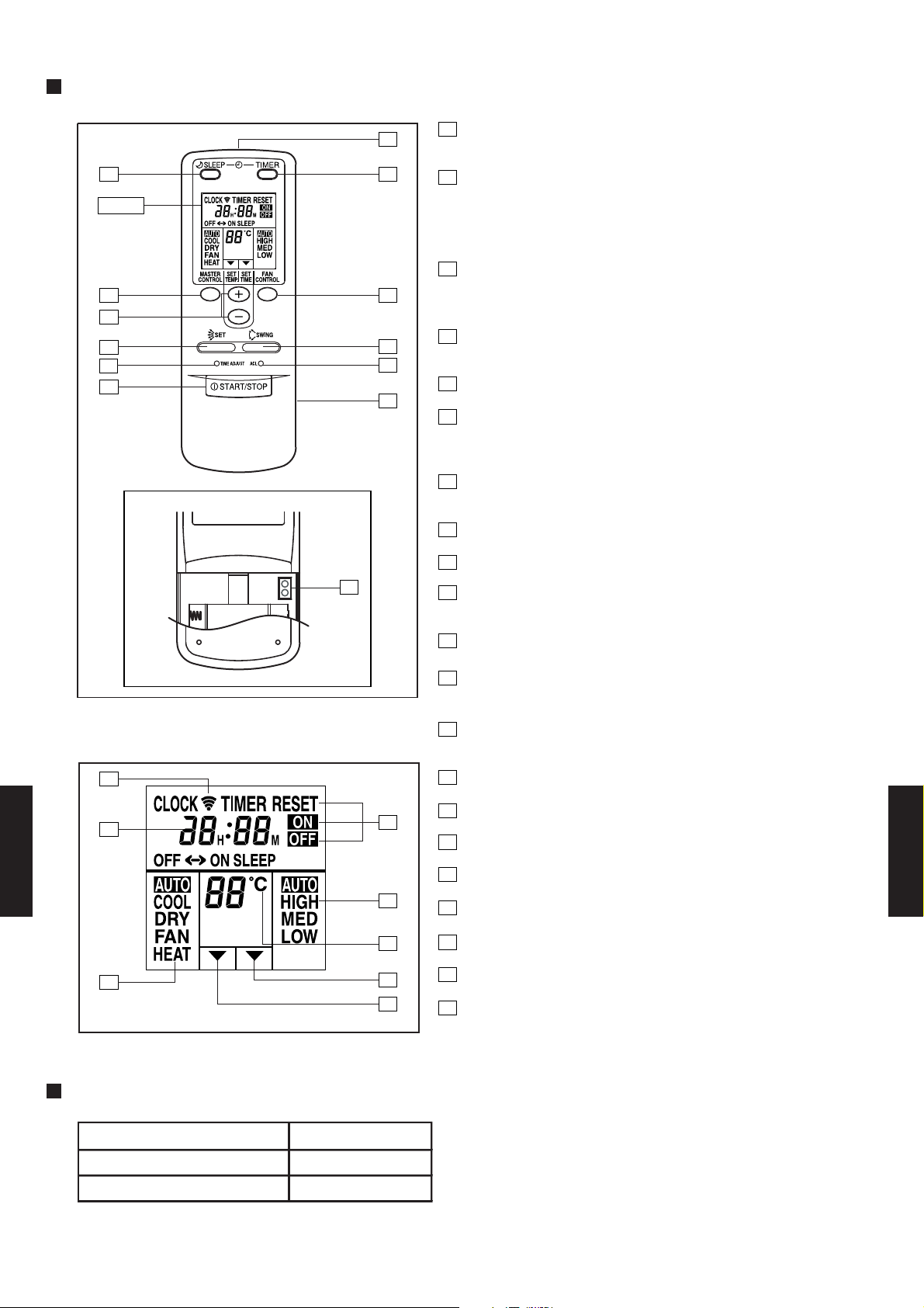
FUNCTIONS
1
5
START/STOP button
Pressed to start and stop operation
Display
3
2
9
10
1
TEST
RUN
13
11
12
64
2
Set temp./Set time/
Set remote controller custom code buttons
Sets the indoor temp./ Sets the current time and on-off time.
/Sets R.C. custom code.
3
Master control / Code change buttons
7
8
Selects the operating mode (AUTO, HEAT, FAN, COOL, DRY).
/Start / end R.C. custom code change. (Max 4 types)
4
Sleep timer button
Pressed to select sleep timer.
5
Signal transmitter
6
Timer button
Pressed to select the timer mode. (OFF TIMER, ON TIMER,
PROGRAM TIMER, TIMER RESET)
7
Fan control button
Selects the fan speed (AUTO, LOW, MED, HIGH).
8
Battery compartment lid
9
Air flow direction set button
10
Time adjust button
Sets the current time.
11
Air flow direction swing button
12
ACL button
Used when replacing batteries or change the code.
13
Test run button
Display panel
14
15
CASSETTE TYPE
AU12-14L
16
17
18
19
20
21
Used when testing the air conditioner after installation.
14
Transmit indicator
15
Clock display
16
Master control display
17
Timer mode display
18
Fan speed display
19
Set temperature display
20
Timer set indicator
21
Temperature set indicator
CASSETTE TYPE
AU12-14L
SPECIFICATION
SIZE (H x W x D mm) 158 x 56 x 20
WEIGHT ( g ) 70
ACCESSORY Holder
- (07 - 04) -
Page 6
7-3. SPECIFICATIONS
AU 12LBAB AU 14LBAB
AO 12LMAKL AO 14LMAKL
Fin Pitch
Fin Pitch
GRILL
GRILL
GRILL
GRILL
6.35 (1/4 inc.) 6.35 (1/4 inc.)
9.52 (3/8 inc.) 12.70 (1/2 inc.)
Rows × Stages
INDOOR
OUTDOOR
-10 to 24
R410A
1250
POE
0 to 43
23(51)
58(128)
4.3(10)
FLARE
70 × 720 × 720
18(40)
54(119)
2.2(5)
650 × 830 × 320
35 × 650 × 650
280 × 710 × 750
743 × 984 × 413
630 × 901 × 36.38
White (5Y9/0.5NN)
Beige (10YR7.5/1.0NN)
235 × 580 × 580 (+ 66)
Copper tube
Aluminium
2 × 30
1.45
Aluminium
2 × 10
1.40
210 × 1000 × 26.6
DC TWIN ROTARY (INVERTER)
1300
Inverter
Copper tube
CASSETTE MODELS
HEAT PUMP TYPE
230V 50Hz
198-264V 50Hz
GROSS
CASING COLOR
DIMENSIONS
H × W × D
mm
mm
NET
GROSS
mm
WEIGHT
kg(lb)
OPERATION(OUTDOOR)
°C
REFRIGERANT
TYPE
REFRIGERANT OIL
TYPE
REMOTE CONTROLLER TYPE
DRAIN PIPE
MATERIAL
SIZE
PIPE
CONNECTION METHOD
SIZE
mm
MAX LENGTH
MAX HEIGHT
NET
COMPRESSOR
TYPE
STARTING METHOD
HEAT
EXCHANGER
TYPE
INDOOR
Coil
Fin
OUTDOOR
Coil
Fin
FAN TYPE x Q'ty
FAN MOTOR OUTPUT
W
NOISE LEVEL
(SOUND
PRESSURE)
COOL/HEAT
INDOOR
dB(A)
OUTDOOR
OUTPUT
Rows × Stages
FAN SPEED
COOL/HEAT
INDOOR
r.p.m
OUTDOOR
MOISTURE REMOVAL
AIR
CIRCULATION
COOL/HEAT
INDOOR
m3/h
OUTDOOR
CURRENT
A
STARTING CURRENT
kW/kW
EER
COP
INPUT POWER
TYPE
MODEL NAME
INDOOR
OUTDOOR
kW
EUROPEAN ENERGY LABEL
Outer diameter 37.0 / Inner diameter 32.0
Wireless
PP
POWER SOURCE
AVAILABLE VOLTAGE RANGE
CAPACITY
COOLING
RATED/MAX
HEATING
RATED/MAX
COOLING B C
kW 3.5 / 4.0 4.0 / 4.6
BTU/h 11,950 / 13,700 13,700 / 15,700
kW 4.0 / 5.0 4.5 / 5.1
BTU/h 13,700 / 17,100 15,400 / 17,400
COOLING RATED/MAX 1.16 / 1.94 1.36 / 2.52
HEATING RATED/MAX 1.40 / 1.94 1.65 / 2.52
COOLING RATED/MAX 5.1 / 8.5 6.0 / 11.0
HEATING RATED/MAX 6.1 / 8.5 7.2 / 11.0
COOLING 3.02 2.94
HEATING 2.86 2.73
l/h (pints/h) 1.3 (2.7) 1.5 (3.2)
High 550 / 550 550 / 550
Med 500 / 500 500 / 500
Low 440 / 440 440 / 440
Quiet - / - - / -
High 2,800 / 2,800 2,800 / 2,800
Low 1500 / 1500 1500 / 1500
High 730 / 730 730 / 730
Med 670 / 670 670 / 670
Low 590 / 590 590 / 590
Quiet - / - - / -
High 780 / 780 780 / 780
Low 400 / 400 400 / 400
INDOOR Turbo × 1 Turbo × 1
OUTDOOR Propeller × 1 Propeller × 1
INDOOR 10 10
OUTDOOR 65 65
High 42 / 42 42 / 42
Med 39 / 39 39 / 39
Low 36 / 36 36 / 36
A 10 10
49 / 51 49 / 51
W
Coil Dimensions
Coil Dimensions
INDOOR
OUTDOOR
CASSETTE TYPE
AU12-14L
INDOOR
OUTDOOR
INDOOR
OUTDOOR
INDOOR
OUTDOOR
LIQUID
GAS
CHARGE g
m 25 (chargeless:10) 25 (chargeless:10)
m 15 15
CASSETTE TYPE
AU12-14L
Note: Specifications are based on the following conditions.
Cooling: Indoor temperature of 27°CDB / 19°CWB,and outdoor temperature of 35°CDB/24°CWB.
Heating: Indoor temperature of 20°CDB / 15°CWB,and outdoor temperature of 7°CDB/6°CWB.
Pipe length : 7.5 m, Height difference : 0 m.(Outdoor unit - Indoor unit)
COOLING
HEATING
mm
- (07 - 05) -
Page 7
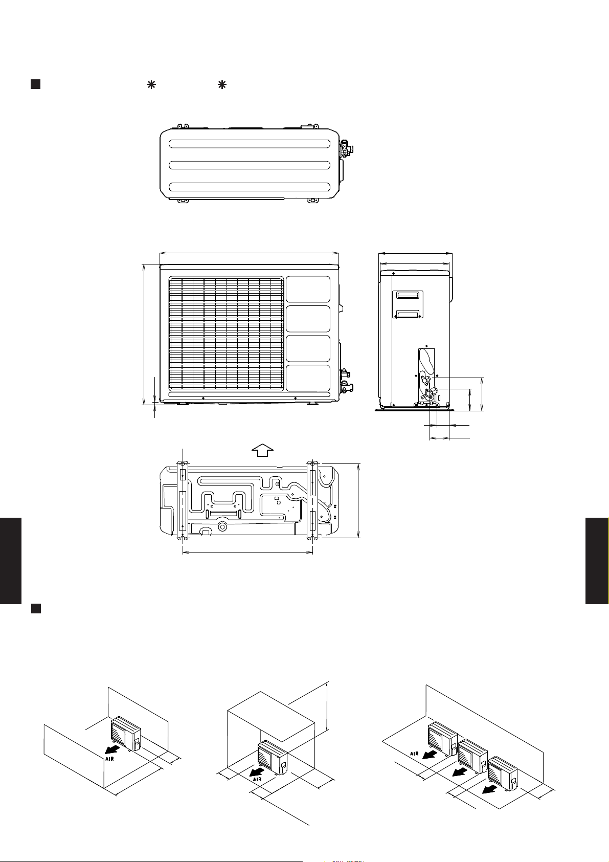
7-4. DIMENSIONS
7-4-1. OUTDOOR UNIT
MODELS : AO 12L, AO 14L
(Unit : mm)
Top view
830
650
12
Front view
Bottom
Air flow
343
350
320
Side view
154
101
58
90
603
Bottom view
CASSETTE TYPE
AU12-14L
CASSETTE TYPE
AU12-14L
MOUNTING POSITION
When there are obstacles at the
back or front sides.
100 mm
or more
100 mm
600 mm
or more
or more
When there are obstacles at the
back, side(s), and top.
600 mm or more
300 mm
25
(
S
0 mm o
er
v
i
c
r
more
e s
p
ac
e)
or more
When there are obstacles at the
back, side with the installation of
more than one unit.
250 mm
or more
250 mm
or more
300 mm
or more
- (07 - 06) -
Page 8
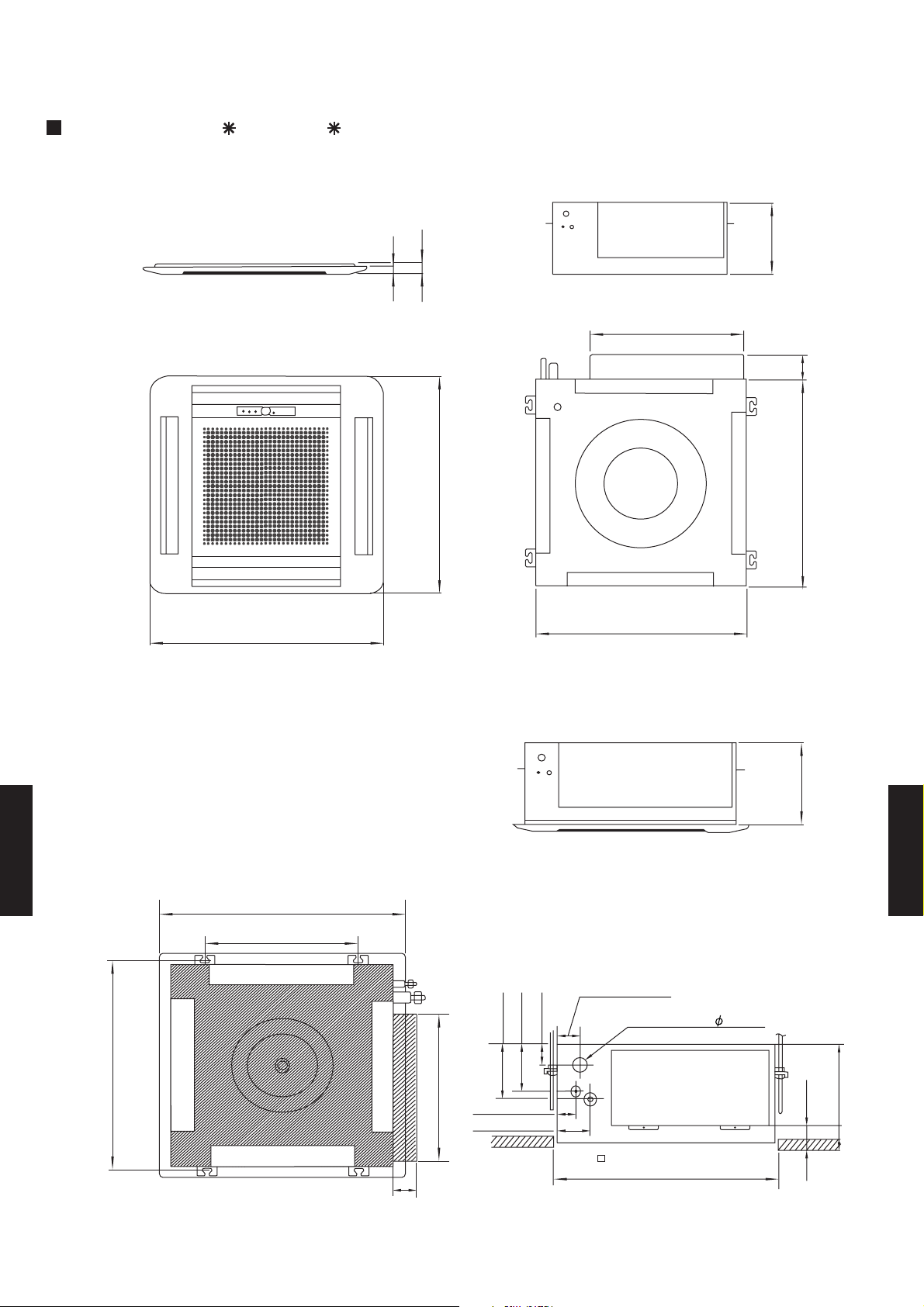
7-4-2. INDOOR UNIT
MODELS : AU 12L, AU 14L
(Unit : mm)
650
Bottom view (Panel)
20
35
440
650
580
235
66
580
Bottom view
245
Side view
CASSETTE TYPE
AU12-14L
(Hanging bolt position)
606
(Grille measurement)
650
(Hanging bolt position)
400
Top view
66
CASSETTE TYPE
AU12-14L
60
47
111
131
440
46
86
(Ceiling opening measurement)
Drain pipe(I.D. 32)
600
245
54
- (07 - 07) -
Page 9
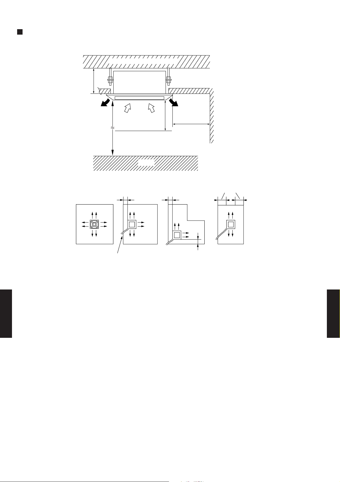
MOUNTING POSITION
Floor
250 mm
or more
Strong and durable ceiling
1,000 mm
2,300 mm
or more
(4 directions) (3 directions)
Piping position
or more
Obstruction
100 or more 100 or more
1,000 mm
or more
100 or more
(2 directions) (2 directions)
100 or more
CASSETTE TYPE
AU12-14L
CASSETTE TYPE
AU12-14L
- (07 - 08) -
Page 10

7-5. REFRIGERANT CIRCUIT
MODELS : AU 12L / AO 12L
9.52mm(3/8")
MODELS : AU 14L / AO 14L
12.70mm(1/2")
CASSETTE TYPE
AU12-14L
CASSETTE TYPE
AU12-14L
- (07 - 09) -
Page 11

7-6. WIRING DIAGRAMS
7-6-1. OUTDOOR UNIT
MODELS : AO 12L, AO 14L
CASSETTE TYPE
AU12-14L
TO INDOOR UNIT
- (07 - 10) -
TO POWER SUPPLY
CASSETTE TYPE
AU12-14L
Page 12

7-6-2. INDOOR UNIT
MODELS : AU 12L, AU 14L
. .
CASSETTE TYPE
AU12-14L
CASSETTE TYPE
AU12-14L
- (07 - 11) -
Page 13

7-7. CAPACITY TABLE
25°CDB
27°CDB
23°CDB
12°CWB
19°CWB
21°CWB
29°CDB
Outdoor temperature
32°CDB
23°CWB
Indoor temperature
18°CWB
15°CWB
16°CWB
18°CDB
21°CDB
Outdoor temperature
24°CDB
Indoor temperature
20°CDB
22°CDB
16°CDB
18°CDB
MODELS : AU 12L / AO 12L
COOLING
AFR 9.2
(°CDB) TC SHC PI TC SHC PI TC SHC PI TC SHC PI TC SHC PI TC SHC PI TC SHC PI
0 4.07 2.91 0.58 4.53 2.93 0.59 4.69 3.14 0.59 5.00 3.20 0.59 5.15 3.45 0.60 5.46 3.44 0.60 5.77 3.66 0.61
5 3.98 2.84 0.69 4.44 2.86 0.70 4.59 3.06 0.71 4.89 3.12 0.71 5.04 3.36 0.72 5.35 3.35 0.72 5.65 3.57 0.73
10 3.87 2.76 0.80 4.32 2.77 0.82 4.46 2.97 0.82 4.76 3.03 0.83 4.90 3.27 0.83 5.20 3.25 0.84 5.49 3.46 0.85
15 3.75 2.67 0.91 4.18 2.68 0.93 4.32 2.88 0.93 4.60 2.93 0.94 4.75 3.16 0.95 5.03 3.15 0.96 5.32 3.35 0.97
20 3.53 2.54 1.00 3.94 2.56 1.02 4.07 2.74 1.02 4.34 2.79 1.03 4.47 3.01 1.04 4.74 3.00 1.05 5.01 3.19 1.06
25 3.44 2.49 1.11 3.83 2.51 1.12 3.96 2.69 1.13 4.22 2.74 1.14 4.36 2.95 1.15 4.62 2.94 1.16 4.88 3.13 1.17
30 3.27 2.40 1.23 3.64 2.42 1.24 3.77 2.59 1.25 4.02 2.64 1.26 4.14 2.85 1.27 4.39 2.84 1.28 4.64 3.02 1.29
35 3.16 2.35 1.35 3.52 2.36 1.37 3.64 2.53 1.38 3.88 2.58 1.39 4.00 2.78 1.40 4.24 2.77 1.41 4.48 2.95 1.43
40 3.00 2.27 1.49 3.34 2.28 1.51 3.46 2.44 1.52 3.69 2.49 1.54 3.80 2.68 1.54 4.03 2.67 1.56 4.26 2.85 1.57
43 2.81 2.17 1.55 3.13 2.18 1.58 3.23 2.34 1.58 3.45 2.38 1.60 3.55 2.57 1.61 3.76 2.56 1.62 3.98 2.73 1.64
AFR : Air flow rate(m3/min) TC : Total capacity (kW ) SHC : Sensible Heat capacity (kW) PI : Power Input (kW )
HEATING
AFR 9.2
(°CDB) (°CWB) TC PI TC PI TC PI TC PI TC PI
-10 -11 3.81 1.57 3.72 1.60 3.63 1.64 3.54 1.67 3.45 1.70
-5 -7 4.22 1.69 4.12 1.73 4.02 1.76 3.92 1.80 3.82 1.84
0 -2 4.82 1.80 4.70 1.84 4.59 1.88 4.48 1.91 4.36 1.95
5 3 4.91 1.59 4.79 1.62 4.67 1.65 4.56 1.68 4.44 1.72
7 6 5.25 1.63 5.13 1.67 5.00 1.70 4.88 1.73 4.75 1.77
10 8 5.46 1.66 5.33 1.70 5.20 1.73 5.07 1.76 4.94 1.80
15 10 5.54 1.66 5.41 1.70 5.28 1.73 5.15 1.77 5.02 1.80
20 15 5.86 1.63 5.72 1.66 5.58 1.70 5.44 1.73 5.30 1.76
24 18 6.04 1.65 5.90 1.69 5.75 1.72 5.61 1.76 5.46 1.79
AFR : Air flow rate(m3/min) TC : Total capacity (kW ) PI : Power Input (kW)
CASSETTE TYPE
AU12-14L
CASSETTE TYPE
AU12-14L
- (07 - 12) -
Page 14

MODELS : AU 14L / AO 14L
Outdoor temperature
32°CDB
23°CWB
Indoor temperature
12°CWB
15°CWB
16°CWB
18°CDB
21°CDB
18°CWB
19°CWB
21°CWB
29°CDB
25°CDB
27°CDB
23°CDB
16°CDB
18°CDB
24°CDB
Indoor temperature
20°CDB
22°CDB
Outdoor temperature
COOLING
AFR 9.2
(°CDB) TC SHC PI TC SHC PI TC SHC PI TC SHC PI TC SHC PI TC SHC PI TC SHC PI
0 4.58 3.20 0.72 5.10 3.22 0.73 5.28 3.45 0.73 5.63 3.51 0.74 5.80 3.79 0.75 6.15 3.77 0.75 6.50 4.02 0.76
5 4.48 3.12 0.85 4.99 3.14 0.87 5.16 3.37 0.87 5.50 3.43 0.88 5.68 3.70 0.88 6.02 3.69 0.89 6.36 3.93 0.90
10 4.37 3.03 0.98 4.86 3.05 1.00 5.03 3.27 1.00 5.36 3.33 1.01 5.53 3.60 1.02 5.86 3.58 1.03 6.19 3.82 1.04
15 4.23 2.93 1.11 4.71 2.95 1.12 4.87 3.17 1.13 5.19 3.22 1.14 5.35 3.48 1.15 5.67 3.47 1.16 5.99 3.69 1.17
20 4.02 2.78 1.20 4.47 2.80 1.22 4.63 3.00 1.23 4.93 3.06 1.24 5.08 3.30 1.24 5.39 3.29 1.26 5.69 3.50 1.27
25 3.95 2.75 1.30 4.40 2.76 1.32 4.55 2.96 1.32 4.85 3.02 1.34 5.00 3.26 1.34 5.30 3.24 1.36 5.60 3.45 1.37
30 3.81 2.67 1.43 4.25 2.69 1.46 4.39 2.88 1.46 4.68 2.93 1.48 4.83 3.17 1.49 5.12 3.16 1.50 5.40 3.36 1.52
35 3.63 2.58 1.59 4.05 2.59 1.62 4.19 2.78 1.63 4.46 2.83 1.64 4.60 3.06 1.65 4.88 3.04 1.67 5.15 3.24 1.68
40 3.43 2.49 1.77 3.83 2.51 1.80 3.96 2.69 1.81 4.22 2.74 1.82 4.35 2.96 1.83 4.61 2.95 1.85 4.87 3.14 1.87
43 3.28 2.39 1.83 3.66 2.41 1.86 3.78 2.58 1.87 4.03 2.63 1.89 4.15 2.84 1.90 4.40 2.83 1.92 4.65 3.01 1.94
AFR : Air flow rate(m3/min) TC : Total capacity (kW ) SHC : Sensible Heat capacity (kW) PI : Power Input (kW )
HEATING
AFR 9.2
(°CDB) (°CWB) TC PI TC PI TC PI TC PI TC PI
-10 -11 4.29 2.28 4.19 2.33 4.09 2.38 3.98 2.43 3.88 2.47
-5 -7 4.55 2.24 4.44 2.29 4.33 2.34 4.22 2.38 4.12 2.43
0 -2 5.13 2.22 5.00 2.27 4.88 2.31 4.76 2.36 4.64 2.41
5 3 5.07 1.86 4.95 1.90 4.83 1.94 4.70 1.98 4.58 2.02
7 6 5.35 1.92 5.23 1.96 5.10 2.00 4.97 2.04 4.84 2.08
10 8 5.54 1.95 5.41 1.99 5.28 2.03 5.15 2.07 5.02 2.12
15 10 5.61 1.97 5.48 2.01 5.34 2.05 5.21 2.09 5.08 2.13
20 15 5.91 1.94 5.77 1.98 5.63 2.02 5.49 2.06 5.35 2.10
24 18 6.06 1.96 5.92 2.00 5.78 2.05 5.63 2.09 5.49 2.13
AFR : Air flow rate(m3/min) TC : Total capacity (kW ) PI : Power Input (kW )
CASSETTE TYPE
AU12-14L
CASSETTE TYPE
AU12-14L
- (07 - 13) -
Page 15

7-8. CAPACITY COMPENSATION FOR PIPE LENGTH
Outdoor unit
is up-side
PIPE LENGTH (m)
Outdoor unit
is bottom-side
HEIGHT DIFFERENCE (m)
COOLING
HEIGHT DIFFERENCE (m)
PIPE LENGTH (m)
Outdoor unit
is bottom-side
Outdoor unit
is up-side
HEATING
AND HEIGHT DIFFERENCE
MODELS : AU 12L / AO 12L
COEFFICIENT OF COMPENSATION FOR HEIGHT DIFFERENCE
5 7.5 10 15 20 25
15 - - - 0.908 0.879 0.852
10 - - 0.943 0.908 0.879 0.852
7.5 - 1.000 0.943 0.908 0.879 0.852
5 1.044 1.000 0.943 0.908 0.879 0.852
0 1.044 1.000 0.943 0.908 0.879 0.852
-5 1.035 0.992 0.936 0.900 0.872 0.845
-7.5 - 0.988 0.932 0.897 0.868 0.841
-10 - - 0.928 0.893 0.864 0.838
-15 - - - 0.886 0.857 0.831
5 7.5 10 15 20 25
15 - - - 0.956 0.947 0.939
10 - - 0.969 0.960 0.952 0.944
7.5 - 0.993 0.971 0.963 0.955 0.946
5 1.006 0.995 0.973 0.965 0.957 0.949
0 1.011 1.000 0.978 0.970 0.962 0.953
-5 1.011 1.000 0.978 0.970 0.962 0.953
-7.5 - 1.000 0.978 0.970 0.962 0.953
-10 - - 0.978 0.970 0.962 0.953
-15 - - - 0.970 0.962 0.953
CASSETTE TYPE
AU12-14L
CASSETTE TYPE
AU12-14L
- (07 - 14) -
Page 16

MODELS : AU 14L / AO 14L
HEIGHT DIFFERENCE (m)
COOLING
Outdoor unit
is up-side
PIPE LENGTH (m)
Outdoor unit
is bottom-side
HEIGHT DIFFERENCE (m)
PIPE LENGTH (m)
Outdoor unit
is bottom-side
Outdoor unit
is up-side
HEATING
COEFFICIENT OF COMPENSATION FOR HEIGHT DIFFERENCE
5 7.5 10 15 20 25
15 - - - 0.949 0.945 0.940
10 - - 0.956 0.949 0.945 0.940
7.5 - 1.000 0.956 0.949 0.945 0.940
5 1.028 1.000 0.956 0.949 0.945 0.940
0 1.028 1.000 0.956 0.949 0.945 0.940
-5 1.019 0.992 0.949 0.941 0.937 0.932
-7.5 - 0.988 0.945 0.937 0.933 0.928
-10 - - 0.941 0.934 0.930 0.925
-15 - - - 0.926 0.922 0.917
5 7.5 10 15 20 25
15 - - - 0.945 0.927 0.909
10 - - 0.967 0.950 0.932 0.914
7.5 - 0.993 0.970 0.953 0.935 0.916
5 1.008 0.995 0.972 0.955 0.937 0.919
0 1.013 1.000 0.977 0.960 0.942 0.923
-5 1.013 1.000 0.977 0.960 0.942 0.923
-7.5 - 1.000 0.977 0.960 0.942 0.923
-10 - - 0.977 0.960 0.942 0.923
-15 - - - 0.960 0.942 0.923
CASSETTE TYPE
AU12-14L
CASSETTE TYPE
AU12-14L
- (07 - 15) -
Page 17

7-9. ADDITIONAL CHARGE CALCULATION
10 15 20 25 (MAX)
20g/m
1250
R410A
MODELS : AU 12L / AO 12L, AU 14L / AO 14L
REFRIGERANT TYPE
REFRIGERANT AMOUNT g
REFRIGERANT CHARGE
PIPE LENGTH m
ADDITIONAL CHARGE g 0 (Charge less) +100 +200 +300
CASSETTE TYPE
AU12-14L
- (07 - 16) -
CASSETTE TYPE
AU12-14L
Page 18

7-10. OPERATION RANGE
Cooling
Dry
Heating 16 to 30°C - -10 to 24°C
AU 12L
AU 14L
AO 12L
AO 14L
Model
Mode
Operation Range
Indoor unit Outdoor unit Indoor temperature Indoor humidity Outdoor temperature
18 to 32°C About 80% or less 0 to 43°C
CASSETTE TYPE
AU12-14L
- (07 - 17) -
CASSETTE TYPE
AU12-14L
Page 19

7-11. FAN PERFORMANCE AND AIR FLOW
7-11-1. AIR VELOCITY DISTRIBUTION
MODELS : AU 12L, AU 14L
4-WAY AIR OUTLET
0.5
11
Unit : m/s
0.25
(m)
4
3
2
1
0
0.25
0.5
0.25
0.5
1
2
22
Note :
Condition
Fan speed : High
Operation mode :FAN
1
2
3
2
1
0.5
0.25
4
4 3 2 1 0 1 2 3 4
(m)
3
2
1
0.25
2
1
0.5
0
4 3 2 1 0 1 2 3 4 5 6 77 6 5
(m)
3
2
1
0
2
1
0.5
0.25 0.25
3 2 1 0 1 2 3
Unit : m/s
2
1
0.5
SIDE VIEW
HORIZONTAL LOUVER
: Downward
(m)
TOP VIEW
HORIZONTAL LOUVER
: Upward
(m)
2
1
0.5
0.25
Unit : m/s
(m)
AIR DISCHARGE ANGLE
SIDE VIEW
HORIZONTAL LOUVER
: Upward
Upward
2
3
Downward
CASSETTE TYPE
AU12-14L
2-WAY AIR OUTLET
(m)
2
1
0
1
2
7 6 5 4 3 2 1 0 1 2 3 4 5 6 7
(m)
3
2
1
0
7 6 5 4 3 2 1 0 1 2 3 4 5 6 7
0.25
0.25
0.5
0.5
CASSETTE TYPE
AU12-14L
Unit : m/s
0
2 1
2
1
0.5
0.25
TOP VIEW
HORIZONTAL LOUVER
: Upward
(m)
3
2
1
2
1
0.5
0.25
Unit : m/s
SIDE VIEW
HORIZONTAL LOUVER
: Upward
(m)
- (07 - 18) -
Page 20

7-11-2. AIR FLOW
m3/h
550
m3/h
500
m3/h
440
m3/h
2800
m3/h
1500
AIR FLOW
LOW
730
NUMBER OF
ROTATIONS
(r.p.m)
670
590
780
400
Indoor unit
Outdoor unit
FAN SPEED
HIGH
MED
LOW
HIGH
MODELS : AU 12L / AO 12L, AU 14L / AO 14L
l/s 153
CFM 324
l/s 139
CFM 294
l/s 122
CFM 259
l/s 778
CFM 1648
l/s 417
CFM 883
CASSETTE TYPE
AU12-14L
CASSETTE TYPE
AU12-14L
- (07 - 19) -
Page 21

7-11-3. DUCT CONNECTION
MODELS : AU 12L, AU 14L
OUTLET AIR
Duct (inside dia.ø150mm)
L
Duct
(Inside Dia. ø150mm)
L
8
240V Hi
L=5m
7
(mmAq)
220V Hi
6
240V Lo
5
220V Lo
4
3
2
1
0
0 2 4 6 8
3
(m
/min)
(mmAq)
8
240V Hi
L=5m
7
220V Hi
6
240V Lo
5
220V Lo
4
3
2
1
0
0 2 4 6 8 10
3
(m
/min)
FRESH AIR
Duct (inside dia.ø150mm)
7
CASSETTE TYPE
AU12-14L
6
5
4
Duct Fan
P
3
Static pressure required
to take in fresh air
2
1
0
0 0.1 0.2 0.3 0.4
3
(m
/min)
(mmAq)
CASSETTE TYPE
AU12-14L
- (07 - 20) -
Page 22

7-12. NOISE LEVEL CURVE
7-12-1. OUTDOOR UNIT
COOLING
MODEL : AO 12L
80
70
60
50
40
30
20
Octave band sound pressure level, dB:(0dB=0.0002µbar)
10
0
63 125 250 500 1,000 2,000 4,000 8,000
Octave band center frequency,Hz
NC-65
NC-60
NC-55
NC-50
NC-45
NC-40
NC-35
NC-30
NC-25
NC-20
NC-15
MODEL : AO 14L
80
70
60
50
40
30
20
Octave band sound pressure level, dB:(0dB=0.0002µbar)
10
0
63 125 250 500 1,000 2,000 4,000 8,000
Octave band center frequency,Hz
NC-65
NC-60
NC-55
NC-50
NC-45
NC-40
NC-35
NC-30
NC-25
NC-20
NC-15
HEATING
MODEL : AO 12L MODEL : AO 14L
80
70
NC-65
60
CASSETTE TYPE
AU12-14L
50
40
30
20
Octave band sound pressure level, dB:(0dB=0.0002µbar)
10
NC-60
NC-55
NC-50
NC-45
NC-40
NC-35
NC-30
NC-25
NC-20
NC-15
80
70
NC-65
60
50
40
30
20
Octave band sound pressure level, dB:(0dB=0.0002µbar)
10
NC-60
NC-55
NC-50
NC-45
NC-40
NC-35
NC-30
NC-25
NC-20
NC-15
CASSETTE TYPE
AU12-14L
0
63 125 250 500 1,000 2,000 4,000 8,000 63 125 250 500 1,000 2,000 4,000 8,000
Octave band center frequency,Hz Octave band center frequency,Hz
0
- (07 - 21) -
Page 23

SOUND LEVEL CHECK POINT
CASSETTE TYPE
AU12-14L
- (07 - 22) -
CASSETTE TYPE
AU12-14L
Page 24

7-12-2. INDOOR UNIT
HIGH
LOW
HIGH
LOW
HIGH
LOW
HIGH
LOW
COOLING
MODEL : AU 12L
80
70
60
50
40
30
20
Octave band sound pressure level, dB:(0dB=0.0002µbar)
10
0
63 125 250 500 1,000 2,000 4,000 8,000
Octave band center frequency,Hz
NC-65
NC-60
NC-55
NC-50
NC-45
NC-40
NC-35
NC-30
NC-25
NC-20
NC-15
MODEL : AU 14L
80
70
60
50
40
30
20
Octave band sound pressure level, dB:(0dB=0.0002µbar)
10
0
63 125 250 500 1,000 2,000 4,000 8,000
Octave band center frequency,Hz
NC-65
NC-60
NC-55
NC-50
NC-45
NC-40
NC-35
NC-30
NC-25
NC-20
NC-15
HEATING
MODEL : AU 12L MODEL : AU 14L
80
70
NC-65
60
CASSETTE TYPE
AU12-14L
50
40
30
20
Octave band sound pressure level, dB:(0dB=0.0002µbar)
10
NC-60
NC-55
NC-50
NC-45
NC-40
NC-35
NC-30
NC-25
NC-20
NC-15
80
70
NC-65
60
50
40
30
20
Octave band sound pressure level, dB:(0dB=0.0002µbar)
10
NC-60
NC-55
NC-50
NC-45
NC-40
NC-35
NC-30
NC-25
NC-20
NC-15
CASSETTE TYPE
AU12-14L
0
63 125 250 500 1,000 2,000 4,000 8,000 63 125 250 500 1,000 2,000 4,000 8,000
0
Octave band center frequency,Hz Octave band center frequency,Hz
- (07 - 23) -
Page 25

SOUND LEVEL CHECK POINT
// //
CENTER
MIC
1.5m
MIC
// //
CENTER
CASSETTE TYPE
AU12-14L
CASSETTE TYPE
AU12-14L
- (07 - 24) -
Page 26

7-13. ELECTRIC CHARACTERISTICS
MODELS : AU 12L / AO 12L, AU 14L / AO 14L
Indoor unit
AU 12L AU 14L
Model Name
Outdoor unit
Voltage V
AO 12L AO 14L
230
Power Supply
50
Rated Value
Frequency Hz
Mode
Cooling Heating Cooling Heating
Current A 5.1 6.1 6.0 7.2
Input kW 1.16 1.40 1.36 1.65
Max Operating Current A 8.5 8.5 11.0 11.0
Starting Current
*1) Wiring Spec.
A
Main Fuse (Circuit breaker)
Current
Power Cable
A
mm
*2)Limited wiring length m
Input kW
2
10
25
3.5
42
10
25
3.5
32
0.035 0.035
Indoor Fan Motor
Full Load Amp. A
Input kW
0.16 0.16
0.15 0.15
Outdoor Fan Motor
Full Load Amp. A
0.73 0.73
*1) Wiring Spec. : Selected Sample
(Selected based on Japan Electrotechnical Standard and Codes Committee E0005)
*2) Limited Wiring length : This is the wiring length in case voltage descent is less than 2%.
When the wiring length becomes long, please select the wiring of a more
larger diameter.
CASSETTE TYPE
AU12-14L
CASSETTE TYPE
AU12-14L
- (07 - 25) -
Page 27

7-14. SAFETY DEVICE
AO 12L AO 14L
FUSE
(SIDE OF POWER SUPPLY TERMINAL)
FUSE ON MAIN PCB
CURRENT FUSE
25A 250V
3.15A 250V
5A 250V
150±5°C OFF
AU 12L AU 14L
3.15A 250V
140±5°C OFF
OUTDOOR UNIT
FAN MOTOR PROTECTION THERMAL PROTECTOR
PROTECTION FORM
CURRENT FUSE
HIGH PRESSURE PROTECTION PRESSURE SWITCH
COMPRESSOR THERMAL SWITCH THERMAL PROTECTOR
INDOOR UNIT
PROTECTION FORM
PCB FUSE CURRENT FUSE
FAN MOTOR PROTECTION THERMAL PROTECTOR
OFF : 4.2±0.1MPa
ON : 3.2±0.15MPa
OFF : 120±5°C
ON : 85±7°C
CASSETTE TYPE
AU12-14L
- (07 - 26) -
CASSETTE TYPE
AU12-14L
Page 28

7-15. FUNCTION SETTING
Auto restart validity/invalidity
Room temperature correct coefficient
Room temperature correct coefficient
Forbidden
Remote control unit single code
Remote control unit single code
INDOOR UNIT
DIP SW
3
JM3
SW 1
Jumper Wire
JM1
JM212
7-15-1. INDOOR UNIT
SWITCH POSITION
Indoor unit control circuit board
CASSETTE TYPE
AU12-14L
JM1
JM3
JM2
CN10
CASSETTE TYPE
AU12-14L
- (07 - 27) -
Page 29

SW 1-1
SW state
OFF
Invalidity
ON
Validity
-2 deg
0 deg
0 deg
-2 deg
-2 deg
0 deg
0 deg
-2 deg
cooling
SW state
ON
OFF
-2 deg
SW 1-2
SW 1-3
heating
dry
ON
ON
ON
0 deg
+4 deg
OFF
OFF
OFF
+2 deg
Jumper wire
JM3
Remote control unit signal code
connect
connect
A
JM2
Disconnect
Disconnect
Disconnect
connect
connectBC
D
Disconnect
7-15-2. SWITCH FUNCTION (INDOOR UNIT)
DIP SWITCH SETTING
SW1-1. Auto restart setting
Auto restart function can be selected by turning this switch ON/OFF.
AUTO RESTART SETTING
( Factory setting)
SW1-2, 1-3. Room temperature correct coefficient of heating.
Decide the heating temperature correct coefficient value of heating.
TEMPERATURE CORRECTION
( Factory setting)
JUMPER WIRE SETTING
JM 1, 2, 3 setting
( Factory setting)
CASSETTE TYPE
AU12-14L
CASSETTE TYPE
AU12-14L
- (07 - 28) -
Page 30

7-16. OPTIONAL PARTS
ADDITIONAL GRILLE
UTG-AGDA-W
The additional grille hides the gap between the ceiling hole
and the outlet grille.
Additional grille (optional parts)
Additonal grille
The ceiling hole
Indoor Unit(grille)
CASSETTE TYPE
AU12-14L
- (07 - 29) -
CASSETTE TYPE
AU12-14L
 Loading...