

Page 1
Refrigerant
A
B
A
A
A
A
B
C
Drain pipe (I.D. 32 mm)
60 mm
305.5 mm
298.5 mm
248.5 mm
120 mm
150 mm
285 mm
127 mm
Drain pipe (I.D. 32 mm)
60 mm
305.5 mm
298.5 mm
248.5 mm
120 mm
150 mm
92 mm
250 mm
Lo
Hi
R410A
Cassette Type
SPLIT TYPE AIR CONDITIONER
INSTALLATION INSTRUCTION
SHEET
(PART NO. 9363217056)
For authorized service personnel only.
WARNING
CAUTION
The basic installation work procedures are the same as conventional refrigerant models.
However, pay careful attention to the following points:
1 Since the working pressure is 1.6 times higher than that of conventional refrigerant models, some of the piping and
installation and service tools are special. (See the table below.)
Especially, when replacing a conventional refrigerant model with a new refrigerant R410A model, always replace the
conventional piping and flare nuts with the R410A piping and flare nuts.
2 Models that use refrigerant R410A have a different charging port thread diameter to prevent erroneous charging with
conventional refrigerant and for safety. Therefore, check beforehand. [The charging port thread diameter for R410A is
1/2 UNF 20 threads per inch.]
3 Be more careful that foreign matter (oil, water, etc.) does not enter the piping than with refrigerant models. Also, when
storing the piping, securely seal the openings by pinching, taping, etc.
4 When charging the refrigerant, take into account the slight change in the composition of the gas and liquid phases, and
always charge from the liquid phase side whose composition is stable.
5 When moving, if the compressor stops during pump down, close the valve immediately. (45, 54 Type only)
Special tools for R410A
Tool name
Gauge manifold
Charge hose
Vacuum pump
Gas leakage detector
Copper pipes
It is necessary to use seamless copper pipes and it is desirable that the amount of
residual oil is less than 40 mg/10 m. Do not use copper pipes having a collapsed,
deformed or discolored portion (especially on the interior surface). Otherwise, the
expansion valve or capillary tube may become blocked with contaminants.
As an air conditioner using R410A incurs pressure higher than when using
conventional refrigerant, it is necessary to choose adequate materials.
Thicknesses of copper pipes used with R410A are as shown in the table. Never
use copper pipes thinner than that in the table even when it is available on
the market.
This mark indicates procedures which, if improperly performed, might lead to the death or serious injury of
the user.
This mark indicates procedures which, if improperly performed, might possibly result in personal harm to
the user, or damage to property.
This air conditioner uses new refrigerant HFC (R410A).
Contents of change
Pressure is high and cannot be measured with a conventional gauge. To prevent erroneous mixing of other
refrigerants, the diameter of each port has been changed.
It is recommended the gauge with seals –0.1 to 5.3 MPa (–76 cmHg to 53 kgf/cm2) for high pressure. –0.1 to
3.8 MPa (–76 cmHg to 38 kgf/cm
To increase pressure resistance, the hose material and base size were changed.
A conventional vacuum pump can be used by installing a vacuum pump adapter.
Special gas leakage detector for HFC refrigerant R410A.
2
) for low pressure.
Thicknesses of Annealed Copper Pipes (R410A)
Pipe outside diameter
6.35 mm (1/4 in.)
9.52 mm (3/8 in.)
12.70 mm (1/2 in.)
15.88 mm (5/8 in.)
19.05 mm (3/4 in.)
Thickness
0.80 mm
0.80 mm
0.80 mm
1.00 mm
1.20 mm
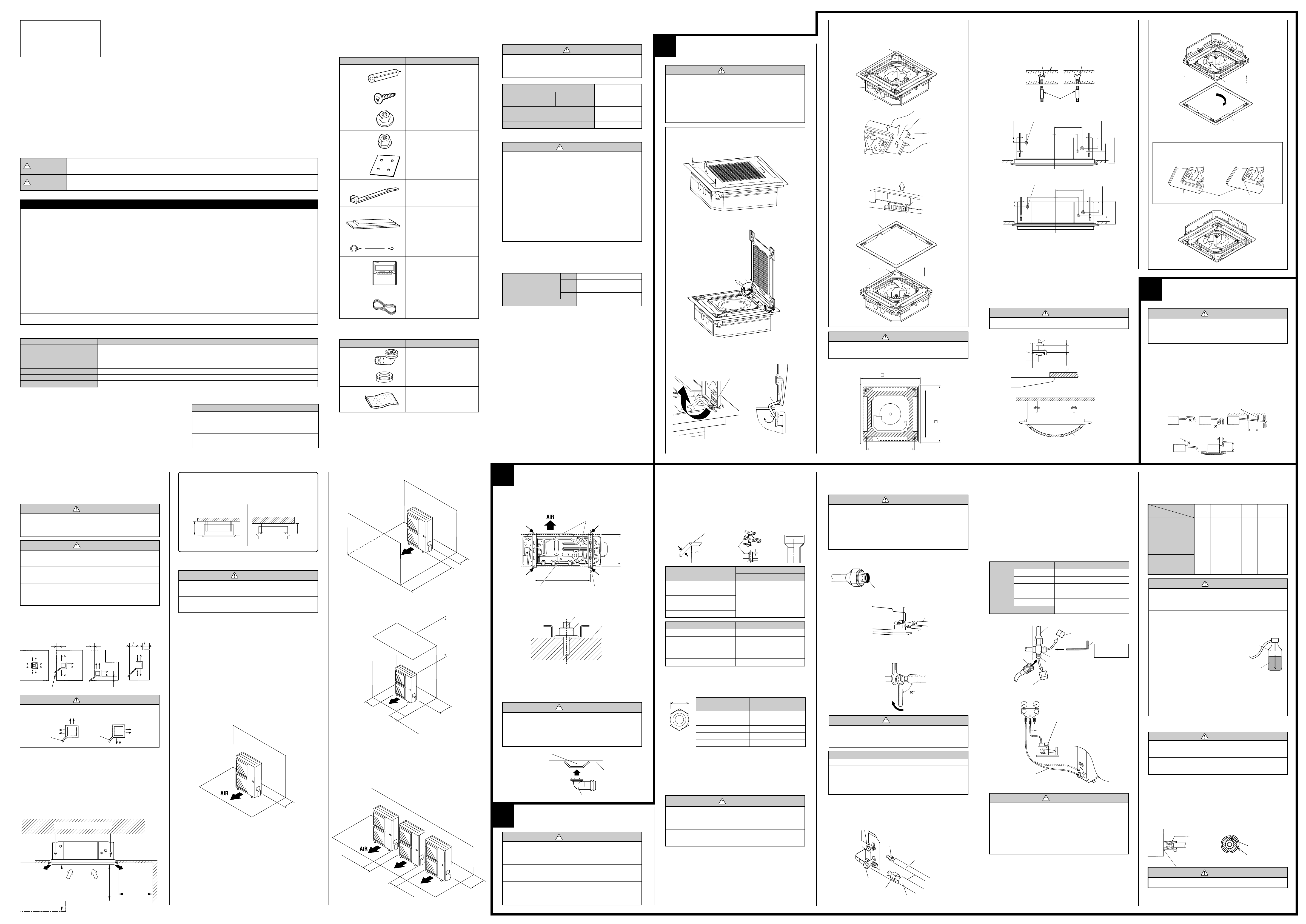
STANDARD PARTS
The following installation parts are furnished.
Use them as required.
INDOOR UNIT ACCESSORIES
Name and Shape
Coupler heat
insulation
Screw
Special nut A
(large flange)
Special nut B
(small flange)
Template
Binder
Blower cover insulation
Hook wire
Remote
controller
Remote controller cord
OUTDOOR UNIT ACCESSORIES
Name and Shape Q’ty Application
Drain pipe
Drain cap
Insulation (seal)
Q’ty
For indoor side pipe joint
2
For installing the remote
2
controller
For installing indoor unit
4
For installing indoor unit
4
For ceiling hole cutting
1
For remote controller and
remote controller cord
1
binding
(small)
For discharged air
2
For installing intake grille
2
1
For connecting the remote
controller
1
1
For outdoor unit drain
piping work (May not be
supplied, depending on
the model.)
2
For filling in a gap at the
entrance of connection
1
cords
Application
CONNECTION PIPE
REQUIREMENT
CAUTION
The maximum lengths of this product are shown in the
following table. If the units are further apart than this,
correct operation can not be guaranteed.
Liquid
Diameter Gas 36 Type 15.88 mm (5/8 in.)
45, 54 Type 19.05 mm (3/4 in.)
Pipe Max. 50 m
length Min. 5 m
Maximum height (between indoor and outdoor)
••
• Use pipe with water-resistant heat insulation.
••
9.52 mm (3/8 in.)
30 m
CAUTION
Install heat insulation around both the gas and liquid pipes.
Failure to do so may cause water leaks.
Use heat insulation with heat resistance above 120 °C.
(Reverse cycle model only)
In addition, if the humidity level at the installation location
of the refrigerant piping is expected to exceed 70%, install
heat insulation around the refrigerant piping. If the expected humidity level is 70-80%, use heat insulation that
is 15 mm or thicker and if the expected humidity exceeds
80%, use heat insulation that is 20 mm or thicker.
If heat insulation is used that is not as thick as specified,
condensation may form on the surface of the insulation.
In addition, use heat insulation with heat conductivity of
0.045 W/(m·K) or less (at 20 °C).
ELECTRICAL REQUIREMENT
••
• Electric wire size and breaker capacity:
••
Power supply cord (mm2)
Connection cord (mm2)
Breaker capacity (A)
••
• Always use H07RN-F or equivalent to the connection cord.
••
••
• Install all electrical works in accordance to the standard.
••
••
• Install the disconnect device with a contact gap of at least 3 mm in all
••
poles nearby the units. (Both indoor unit and outdoor unit)
••
• Install the circuit breaker nearby the units.
••
MAX.
MIN.
MAX.
MIN.
4.0
2.5
2.5
1.0
20
OPTIONS
The following options are available.
••
• ADDITIONAL GRILLE ASSY: UTG-AGEA-W (P/N 900223002)
••
••
• Simple remote controller: UTB-YPB (P/N 9077582006)
••
INSTALLATION PROCEDURE
1
INDOOR UNIT INSTALLATION
WARNING
● Install the air conditioner in a location which can withstand a load do at least five times the weight of the
main unit and which will not amplify sound or vibration. If the installation location is not strong enough,
the indoor unit may fall and cause injuries.
● If the job is done with the panel frame only, there is a
risk that the unit will come loose. Please take care.
REMOVING THE INTAKE GRILLE
(1) Push the intake grille pushbuttons (two places).
(2) Open the intake grille.
PUSH
OPEN
(3) Remove the grille hinge wire.
• Pull up while pressing the B section.
Part A detail view Part A section view
Grille hinge wire
(4) Remove the intake grille.
REMOVING THE PANEL FRAME
• Pull up the corner sections (A) of the panel frame as shown in
the figure (4 locations).
Part A detail view
• Pull up in the direction of the arrow while holding down the C
section of the figure (4 locations).
Part B detail view
Panel frame
Panel base
CAUTION
Always remove the panel frame after removing the intake
grille.
1. POSITION THE CEILING HOLE AND HANGING
BOLTS
940 mm
(Grille measurement)
750 mm
(Hanging bolt position)
890 mm
750 mm
(Hanging bolt position)
(Ceiling opening measurement)
2. HANGING PREPARATIONS
• Firmly fasten the hanging bolts as shown in the figure or by another
method.
• Install the hanging bolts at a place where they would be capable of
holding a weight of at least 490 N (50 kgf) per bolt.
Hole-in anchor
Hole-in plug Concrete Insert
Hanging bolt M10
(A) Standard setting
(B) Slender setting
3. BODY INSTALLATION
[The ceiling rear height is 285 mm or more.] [Standard setting]
[The ceiling rear height is 250 mm or more.] [Slender setting]
(1) Install special nut A, then special nut B onto the hanging bolt.
(2) Raise the body and mount its hooks onto the hanging bolt between
the special nuts.
(3) Turn special nut B to adjust the height of the body.
(4) Leveling
Using a level, or vinyl hose filled with water, fine adjust so that the
body is level.
WARNING
Perform final tightening by tightening the double nut firmly.
Special nut A
Special nut B
Hanging bolt
* Allowable space between the unit and the ceiling 5 mm or less
Hook
30 mm or
more
After installing the body,
tighten the nuts.
Ceiling
* Must fit tightly against ceiling
without any gap.
Vinyl hose
INSTALLING THE PANEL FRAME
Panel base
*90° Turn
Panel frame
* With slender setting, turn the panel frame 90° as shown in the dia-
gram above.
Grille setting method has been changed at the marked positions on the panel frame and panel base.
(A) Standard setting (B) Slender setting
Mark
Panel frame
No mark
(Example)
* Appearance of slender setting
2
INSTALLING DRAIN PIPE
CAUTION
Install the drain pipe in accordance with the instructions
in this installation instruction sheet and keep the area warm
enough to prevent condensation. Problems with the pip-
ing may lead to water leaks.
NOTE: Install the drain pipe.
••
• Install the drain pipe with downward gradient (1/50 to 1/100) and so
••
there are no rises or traps in the pipe.
••
• Use general hard polyvinyl chloride pipe (VP25) [outside diameter
••
32 mm] and connect it with adhesive (polyvinyl chloride) so that there
is no leakage.
••
• When the pipe is long, install supporters.
••
••
• Do not perform air bleeding.
••
••
• Always heat insulate the indoor side of the drain pipe.
••
••
• When desiring a high drain pipe height, raise it up to 800 mm or less
••
from the ceiling within a range of 150 mm from the body. A rise dimension over this range will cause leakage.
Supporter
Rise
Air bleeding
Trap
150 mm or less
1.5 to 2.0 m
Max. 800 mm
SELECTING THE MOUNTING
POSITION
Decide the mounting position with the customer as follows:
WARNING
Select installation locations that can properly support the
This mechanism enables the cassette body to move 35 mm downward and realizes installation to the space of 250 mm. No special
works and option is needed.
You can select 2-way setting
(B) Slender setting(A) Standard setting
••
3
1. OUTDOOR UNIT PROCESSING
(1) Outdoor unit to be fasten with bolts at the four places indicated by the
arrows without fail.
Bottom side
OUTDOOR UNIT
INSTALLATION
Drain cap
mounting place
weight of the indoor and outdoor units. Install the units
securely so that they do not topple or fall.
285 mm
or more
250 mm
or more
CAUTION
1 Do not install where there is the danger of combustible
gas leakage.
2 Do not install the unit near heat source of heat, steam,
or flammable gas.
3 If children under 10 years old may approach the unit,
take preventive measures so that they cannot reach
the unit.
Especially, the installation place is very important for the split type air
conditioner because it is very difficult to move from place to place after the
first installation.
Decide the mounting position together with the customer as follows:
The discharge direction can be selected as shown below.
(4 directions)
Piping position
100 mm or more
(3 directions)
100 mm or more
(2
directions
100 mm or more
1,000 mm or more
)
(2
directions
)
CAUTION
Since 2-way outlet as shown below causes performance
problems, do not set it.
Pipe
Pipe
INDOOR UNIT
(1) Install the indoor unit on a place having a sufficient strength so that it
withstands against the weight of the indoor unit.
(2) The inlet and outlet ports should not be obstructed; the air should be
able to blow all over the room.
(3) Leave the space required to service the air conditioner.
(4) The ceiling rear height as shown in the figure.
(5) A place from where the air can be distributed evenly throughout the
room by the unit.
(6) A place from where drainage can be extracted outdoors easily.
(7) Install the unit where noise and vibrations are not amplified.
Strong and durable ceiling
OUTDOOR UNIT
WARNING
1 Install the unit where it will not be tilted by more than
5˚.
2 When installing the outdoor unit where it may exposed
to strong wind, fasten it securely.
(1) Install the outdoor unit in a location which can withstand the weight
of the unit and vibration, and which can install horizontally.
(2) Provide the indicated space to ensure good airflow.
(3) If possible, do not install the unit where it will be exposed to direct
sunlight.
(If necessary, install a blind that does not interfere with the airflow.)
(4) Do not install the unit near a source of heat, steam, or flammable
gas.
(5) During heating operation, drain water flows from the outdoor unit.
Therefore, install the outdoor unit in a place where the drain water
flow will not be obstructed. (Reverse cycle model only)
(6) Do not install the unit where strong wind blows or where it is very
dusty.
(7) Do not install the unit where people pass.
(8) Install the outdoor unit in a place where it will be free from being dirty
or getting wet by rain as much as possible.
(9) Install the unit where connection to the indoor unit is easy.
••
• When there are obstacles at the back side.
••
100 mm
or more
AIR
100 mm
or more
600 mm
or more
••
• When there are obstacles at the back, side(s), and top.
••
600-1000 mm*
100-300 mm*
AIR
250 mm or more
(Service space)
If the space is larger than that is stated, the condition
*
will be the same as that there are no obstacles.
••
• When there are obstacles at the back side with the installation of
••
more than one unit.
300 mm
or more
650 mm
Drain pipe
mounting place
(2) Fix securely with bolts on a solid block. (Use 4 sets of commercially
available M10 bolt, nut and washer.)
(3) Since the drain water flows out of the outdoor unit during heating
operation, install the drain pipe and connect it to a commercial 16 mm
hose. (Reverse cycle model only)
(4) When installing the drain pipe, plug all the holes other than the drain
pipe mounting hole in the bottom of the outdoor unit with putty so
there is no water leakage. (Reverse cycle model only)
Bolt
Nut
4-ø 12 hole
Block
CAUTION
When the outdoor temperature is 0 °C or less, do not
use the accessory drain pipe and drain cap.
If the drain pipe and drain cap are used, the drain water
in the pipe may freeze in extremely cold weather.
(Reverse cycle model only)
Drain pipe mounting hole
Base
Drain pipe
4
CONNECTING THE PIPE
370 mm
CAUTION
Floor
2,300 mm
or more
Obstruction
1,000 mm
or more
1,000 mm
or more
250 mm
or more
250 mm
or more
300 mm
or more
1 Do not use mineral oil on flared part. Prevent mineral
oil from getting into the system as this would reduce
the lifetime of the units.
2 While welding the pipes, be sure to blow dry nitrogen
gas through them.
3 The maximum lengths of this product are shown in the
table. If the units are further apart than this, correct
operation can not be guaranteed.
1. FLARING
(1) Cut the connection pipe to the necessary length with a pipe cutter.
(2) Hold the pipe downward so that cuttings will not enter the pipe and
remove the burrs.
(3) Insert the flare nut (always use the flare nut attached to the indoor
and outdoor units respectively) onto the pipe and perform the flare
processing with a flare tool.
Use the special R410A flare tool, or the conventional flare tool.
Check if [L] is flared uniformly
and is not cracked or scratched.
Die
A
Pipe
Pipe outside diameter
6.35 mm (1/4 in.)
9.52 mm (3/8 in.)
12.70 mm (1/2 in.)
15.88 mm (5/8 in.)
19.05 mm (3/4 in.)
Pipe outside diameter
6.35 mm (1/4 in.)
9.52 mm (3/8 in.)
12.70 mm (1/2 in.)
15.88 mm (5/8 in.)
19.05 mm (3/4 in.)
When using conventional flare tools to flare R410A pipes, the dimension
A should be approximately 0.5 mm more than indicated in the table (for
flaring with R410A flare tools) to achieve the specified flaring. Use a thickness gauge to measure the dimension A.
Width across flats
Pipe outside
diameter
6.35 mm (1/4 in.)
9.52 mm (3/8 in.)
12.70 mm (1/2 in.)
15.88 mm (5/8 in.)
19.05 mm (3/4 in.)
Dimension A (mm)
Flare tool for R410A, clutch type
0 to 0.5
Dimension B
Width across flats
(mm)
-0.4
9.1
13.2
16.6
19.7
24.0
of Flare nut
17 mm
22 mm
26 mm
29 mm
36 mm
B
0
2. BENDING PIPES
The pipes are shaped by your hands. Be careful not to collapse them.
Do not bend the pipes in an angle more than 90°.
When pipes are repeatedly bend or stretched, the material will harden,
making it difficult to bend or stretch them any more. Do not bend or
stretch the pipes more than three times.
CAUTION
1 To prevent breaking of the pipe, avoid sharp bends.
Bend the pipe with a radius of curvature of 150 mm or
over.
2 If the pipe is bent repeatedly at the same place, it will
break.
3. CONNECTION PIPES
Indoor unit
(1) Detach the caps and plugs from the pipes.
CAUTION
1 Be sure to apply the pipe against the port on the in-
door unit correctly. If the centering is improper, the flare
nut cannot be tightened smoothly. If the flare nut is
forced to turn, the threads will be damaged.
2
Do not remove the flare nut from the indoor unit pipe
until immediately before connecting the connection pipe.
(2) Centering the pipe against port on the indoor unit, turn the flare nut
with your hand.
To prevent gas leakage, coat the flare
surface with alkylbenzene oil (HAB).
Do not use mineral oil.
Connection pipe
Indoor unit
(3) When the flare nut is tightened properly by your hand, use a torque
wrench to finally tighten it.
Holding spanner
Body side
CAUTION
Hold the torque wrench at its grip, keeping it in the right
angle with the pipe, in order to tighten the flare nut
correctly.
Flare nut Tightening torque
6.35 mm (1/4 in.) dia.
9.52 mm (3/8 in.) dia.
12.70 mm (1/2 in.) dia.
15.88 mm (5/8 in.) dia.
19.05 mm (3/4 in.) dia.
Outdoor unit
Tighten the flare nut of the connection pipe at the outdoor unit valve connector. The tightening method is the same as that as at the indoor side.
3-way valve
(Liquid)
3-way valve
(Gas)
Flare nut
14 to 18 N·m (140 to 180 kgf·cm)
33 to 42 N·m (330 to 420 kgf·cm)
50 to 62 N·m (500 to 620 kgf·cm)
63 to 77 N·m (630 to 770 kgf·cm)
100 to 110 N·m (1000 to 1100 kgf·cm)
Flare nut
Connection pipe
(Gas)
(Gas)
Connection pipe
(Liquid)
Torque wrench
Connection pipe
(Liquid)
4. VACUUM
(1) Remove the cap, and connect the gauge manifold and the vacuum
pump to the charging valve by the service hoses.
(2) Vacuum the indoor unit and the connecting pipes until the pressure
gauge indicates –0.1 MPa (–76 cmHg).
(3) When –0.1 MPa (–76 cmHg) is reached, operate the vacuum pump
for at least 60 minutes.
(4) Disconnect the service hoses and fit the cap to the charging valve to
the specified torque.
(5) Remove the blank caps, and fully open the spindles of the 2-way
and 3-way valves with a hexagon wrench [Torque: 6~7 N·m (60 to
70 kgf·cm)].
(6) Tighten the blank caps of the 2-way valve and 3-way valve to the
specified torque.
Tightening torque
6.35 mm (1/4 in.)
Blank
cap
Service hose
with valve core
9.52 mm (3/8 in.)
12.70 mm (1/2 in.)
15.88 mm (5/8 in.)
19.05 mm (3/4 in.)
Charging port cap
Connecting pipe
Outdoor unit
Cap
Gauge manifold
Service hose
1 Do not purge the air with refrigerants, but use a vacuum
pump to vacuum the installation! There is no extra refrigerant in the outdoor unit for air purging!
2 Use a vacuum pump and gauge manifold and charg-
ing hose for R410A exclusively. Using the same vacuum
for different refrigerants may damage the vacuum pump
or the unit.
20 to 25 N·m (200 to 250 kgf·cm)
20 to 25 N·m (200 to 250 kgf·cm)
25 to 30 N·m (250 to 300 kgf·cm)
30 to 35 N·m (300 to 350 kgf·cm)
35 to 40 N·m (350 to 400 kgf·cm)
10 to 12 N·m (100 to 120 kgf·cm)
Blank cap
Hexagon wrench
3-way valve
Charging port
Vacuum pump
CAUTION
Use a 4 mm
hexagon wrench.
5. ADDITIONAL CHARGE
Refrigerant suitable for a piping length of 20 m is charged in the outdoor
unit at the factory.
When the piping is longer than 20 m, additional charging is necessary.
For the additional amount, see the table below.
Pipe length
Model type
36,000 BTU/h class
(cooling model)
(Reverse cycle model)
45,000 BTU/h class
(cooling model)
(Reverse cycle model)
54,000 BTU/h class
(cooling model)
(Reverse cycle model)
20 m
(66 ft)
None
None
30 m
(99 ft)
300 g
(10.6 oz)
400 g
(14.1 oz)
40 m
(132 ft)
600 g
(21.2 oz)
800 g
(28.2 oz)
50 m
(164 ft)
900 g
(31.8 oz)
1200 g
(42.3 oz)
g/m
(oz/ft)
30 g/m
(1.06 oz/3.3 ft)
40 g/m
(1.41 oz/3.3 ft)
CAUTION
1 When moving and installing the air conditioner, do not
mix gas other than the specified refrigerant R410A
inside the refrigerant cycle.
2 When charging the refrigerant R410A, always use
an electronic balance for refrigerant charging (to
measure the refrigerant by weight).
3 When charging the refrigerant,
take into account the slight change
in the composition of the gas and
liquid phases, and always charge
from the liquid phase side whose
composition is stable.
4 Add refrigerant from the charging valve after the
completion of the work.
5 The maximum length of piping is 50 m. If the units are
further apart than this, correct operation can not be
guaranteed.
Gas
R410A
Liquid
6. GAS LEAKAGE INSPECTION
CAUTION
1 After connecting the piping, check the all joints for gas
leakage with gas leak detector.
2 When inspecting gas leakage, always use the vacuum
pump for pressure. Do not use nitrogen gas.
7. HEAT INSULATION ON THE PIPE JOINTS
(INDOOR SIDE ONLY)
After checking for gas leaks, insulate by wrapping insulation around the
two parts (gas and liquid) of the indoor unit coupling, using the coupler
heat insulation.
After installing the coupler heat insulation, wrap both ends with vinyl tape
so that there is no gap.
Coupler heat insulation
Body
Be sure to overlap the
insulation
CAUTION
Must fit tightly against body without any gap.
No gap
Coupler heat insulation
- Continued on back -
••
• When there are obstacles at the back and front sides.
Page 2
5
3
2
1
2
3
3
2
1
T
N
1
R
S
123
O
F
F
SW 4
123
O
F
F
SW 1
Indoor unit PC board
A
A
A
P. D 120
160
45°
45°
ø100
ø70
113
334.2
P. D 88
97
R
S
TN123
OFF
123
OFF
SW1
OFF
123
SW4
POWER
WARNING
1 The rated voltage of this product is 400 V 3ø 50 Hz.
2 Before turning on, verify that the voltage is within the
342 V to 457 V range.
3 Always use a special branch circuit and install a spe-
cial receptacle to supply power to the air conditioner.
4 Use a special branch circuit breaker and receptacle
matched to the capacity of the air conditioner.
(Install in accordance with standard.)
5 Perform wiring work in accordance with standards
so that the air conditioner can be operated safely and
positively.
6 Install a leakage special branch circuit breaker in
accordance with the related laws and regulations
and electric company standards.
CAUTION
1 The power source capacity must be the sum of the air
conditioner current and the current of other electrical
appliances. When the current contracted capacity is
insufficient, change the contracted capacity.
2 When the voltage is low and the air conditioner is
difficult to start, contact the power company the
voltage raised.
3 This air conditioner must be connected to a power
source that has an electrical impedance of 0.16 Ω or
less or has a supply current of 100 A or greater. If the
power supply does not meet the specifications,
contact the power company.
HOW TO CONNECT WIRING TO THE
TERMINALS
A. For solid core wiring (or F-cable)
(1) Cut the wire end with a wire cutter or wire-cutting pliers, then strip
the insulation to about 25 mm to expose the solid wire.
(2) Using a screwdriver, remove the terminal screw(s) on the terminal
board.
(3) Using pliers, bend the solid wire to form a loop suitable for the
terminal screw.
(4) Shape the loop wire properly, place it on the terminal board and
tighten securely with the terminal screw using a screwdriver.
B. For strand wiring
(1) Cut the wire end with a wire cutter or wire-cutting pliers, then strip
the insulation to about 10 mm to expose the strand wiring.
(2) Using a screwdriver, remove the terminal screw(s) on the terminal
board.
(3) Using a round terminal fastener or pliers, securely clamp a round
terminal to each stripped wire end.
(4) Position the round terminal wire, and replace and tighten the
terminal screw using a screwdriver.
Round
terminal
Screw with
special washer
Round
terminal
Strip 25 mm
Wire
A. Solid wire
Insulation
B. Strand wire
Loop
Strip 10 mm
Screw with
special washer
Round terminal
Terminal
board
Wire
Terminal block
2. CONNECTION CORD PREPARATION
30 mm
For earth
Power supply cord
40 mm or more
or connection cord
3. INDOOR UNIT
(1) Remove the control box cover and cover (wire) B and install the con-
nection cord.
Cover (wire) B
Control box cover
(2) After wiring is complete, clamp the remote controller cord and con-
nection cord with the cord clamp.
(3) Install the control box cover and cover (wire) B.
Connection cord
(To the outdoor unit)
Cord clamp
Remote controller cord
Ceiling height setting
Set the DIP switch for the ceiling height according to the table below.
Ceiling height
(m)
2.5 - 3.0
3.0 - 3.5
More than 3.5
Less than 2.5
Dip switch
(SW4)
Normal
High ceiling 1
High ceiling 2
Low ceiling
Indoor unit
PC board
DIP-SW4
1
–
–
–
–
2
OFF
ON
OFF
ON
3
OFF
OFF
ON
ON
CAUTION
1 If the setting for a low ceiling is selected, the capacity
of the air conditioner decreases slightly.
2 Do not set any switches other than those specified
in this sheet or the remote controller installation instruction sheet. The air conditioner may not operate
correctly if any switches other than those specified are
changed.
4. OUTDOOR UNIT
CAUTION
When connecting the power supply cord, make sure that
the phase of the power supply matches with the phase of
the terminal board. If the phases do not match, the
compressor will rotate in reverse and will not be able to
compress.
(2) Valve cover removal.
• Remove the one mounting screw.
• Remove the valve cover by sliding upward.
Valve cover
Hook
(4 places)
(3) Connect the power supply cord and the connection cord to terminal.
(4) Fasten the power supply cord and connection cord with cord clamp.
Control box
Terminal
Cord clamp
(5) Power supply cord and connection cord should be fixed with cable
clip as shown in the figure.
Fill in a gap at the entrance of the cords with insulation (seal).
• 36,000 BTU/h class (cooling model)
Power supply cord and
connection cord
Cable clip
Insulation
(Seal)
• 36,000 BTU/h class (Reverse cycle model)
• 45,000 BTU/h class
• 54,000 BTU/h class
Power supply cord and
connection cord
7
GRILLE INSTALLATION
BLOWER COVER INSULATION
Install the blower cover insulation only when the outlet direction is not
specified.
Two blower cover insulations are packed with the indoor unit.
Install the blower cover insulation at the diffuser position shown in the
figure. At this time, use the piping position as the criteria.
2 direction example
Panel
base
Drain
pan
Blower cover
insulation
(Piping direction)
INSTALLING THE INTAKE GRILLE
(1) Mount the grille hinge wire to the hook shaft as shown in the
figure.
A-A Section view
(2) Install the hook wire.
• Pass the hook wire through the panel base from the rear side as
shown in the figure, and fasten to the reinforced metal fitting of
the intake grille using a screw.
Hook wire
RFM (grille)
Section view
Hook wire
Screw
(3) Loosen the screw, put the loop of the hook wire over it, and tighten
the screw again.
6
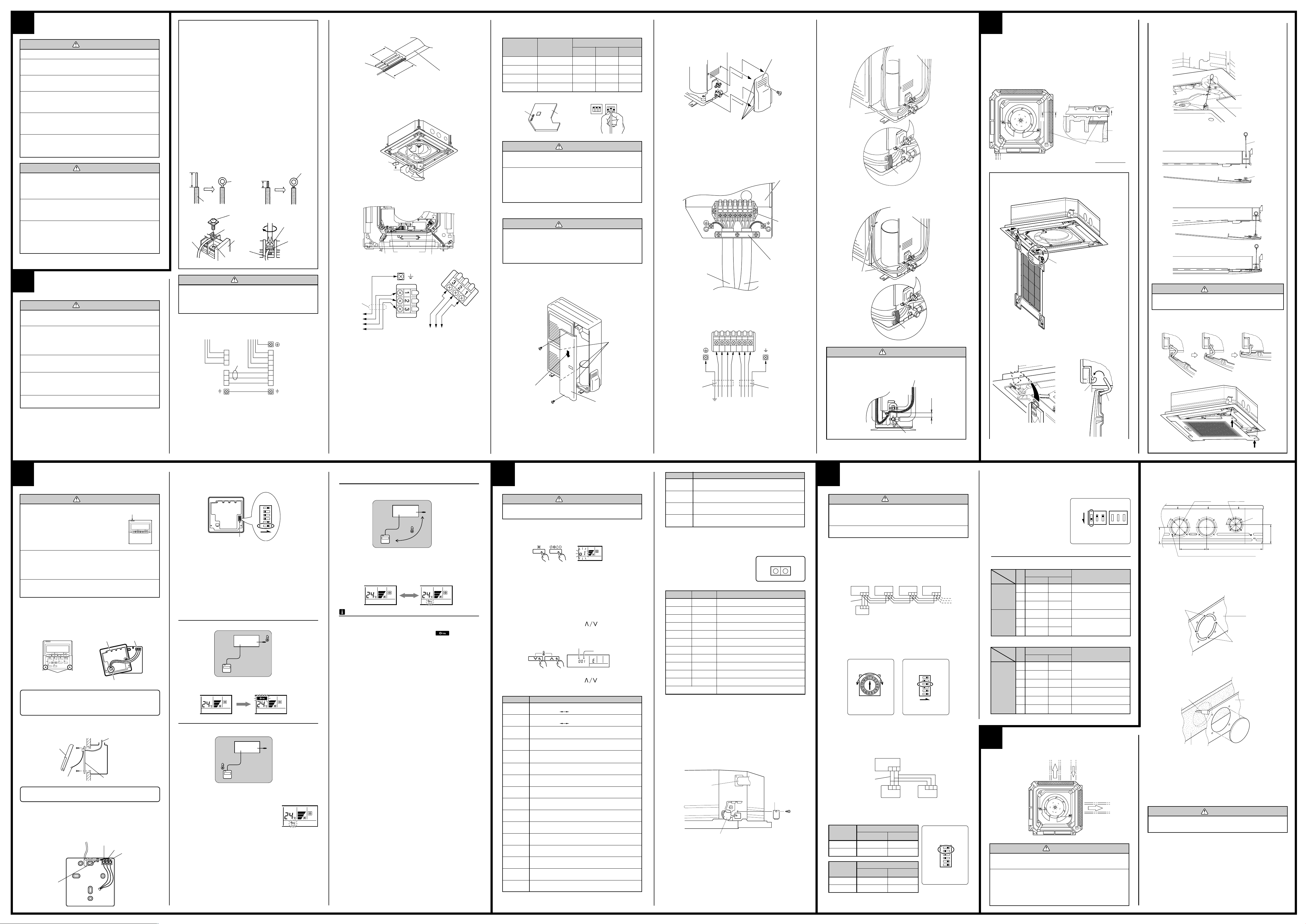
ELECTRICAL WIRING
WARNING
1 Before starting work, check that power is not being
supplied to the indoor unit and outdoor unit.
2 Match the terminal board numbers and connection
cord colors with those of the outdoor unit.
Erroneous wiring may cause burning of the electric
parts.
3 Connect the connection cords firmly to the terminal
board. Imperfect installation may cause a fire.
4 Always fasten the outside covering of the connection
cord with the cord clamp. (If the insulator is chafed,
electric leakage may occur.)
5 Always connect the ground wire.
CAUTION
Do not bundle the remote controller cord, or wire the remote controller cord in parallel, with the indoor unit connection wire (to the outdoor unit) and the power supply
cord. It may cause erroneous operation.
1. CONNECTION DIAGRAMS
Remote controller
Black
White
Red
Indoor unit
side terminal
Power supply
Power
line
Outdoor unit
side terminal
Connection
cord
OUTDOOR
UNIT
Terminal board
(Indoor unit)
Black
White
Remote
controller
Red
Terminal board
(1) Service cover removal
• Remove the two mounting screws.
• Remove the service cover by pushing downwards.
Direction of the service
cover removal
Service cover
Hook
(3 places)
Power supply cord
For earth
Power supply cord
30 mm
EARTH
40 mm or more
Indoor unit
Connection cord
(indoor unit and
outdoor unit
connection cord)
Power supply cord
and connection cord
Connection cord
Cable clip
(2 places)
Insulation
(Seal)
CAUTION
Do not make power supply cord and connection cord come
in contact with valve (Gas).
Power supply cord
and connection cord
Gap
CAUTION
Install the intake grille hook wire to the grille assembly. If it falls, it may cause injuries.
(4) Bring up the intake grille by pushing it up at an angle as shown in
the figure, and fasten.
• Latch the grille hinge wire to the hook shaft, and fasten.
Part A detail view Part A section view
Hook shaft
Grille hinge
wire
8
REMOTE CONTROLLER
SETTING
CAUTION
1 In order to detect the room temperature
correctly when using the temperature
sensor of the remote controller, do not
install the remote controller in a place
where it will be exposed to direct sunlight or directly below the air outlet of
the indoor unit.
2 When installing the remote controller and cord near a
source of electromagnetic waves, separate the remote
controller from the source of the electromagnetic waves
and use shielded cord.
3 Do not touch the remote controller PC board and PC
board parts directly with your hands.
1. INSTALLING THE REMOTE CONTROLLER
(1) Open the operation panel on the front of the remote controller, re-
move the two screws indicated in the following figure, and then remove the front case of the remote controller.
Front case
(back side)
DAY
CLOCK ADJUST
DAY OFF
ENERGY
DELETE SET
Screws
THERMO
SAVE
SENSOR
Connector
Connector
Rear case
SET BACK
When installing the remote controller, remove the connector from the
front case. The wires may break if the connector is not remove and the
front case hangs down.
When installing the front case, connect the connector to the front case.
(2) Install the rear case to the wall, etc. with the two tapping screws.
Refer to the following information to install the remote controller wires.
Front case
Install the remote controller wires so as not to be direct touched with
your hand.
2. ROUTING THE REMOTE CONTROLLER WIRES
(1) Install the remote controller wires to the terminals on the top of the
rear case as shown in the following figure.
(2) Fasten the wires with the binder.
(Example)
Binder
1. Red
Temperature sensor
Rear case
Remote controller
wires
2. White
3. Black
3. SETTING THE DIP SWITCHES
When using a battery (memory backup)
ON
OFF
1
2
3
4
5
6
DIP Switch
Change the DIP switch setting to use batteries. (The DIP switch is not set
to use batteries at the factory.)
Change DIP switch No. 6 from OFF to ON.
If batteries are not used, all of the settings stored in memory will be deleted if there is a power failure.
ON
4. SETTING THE ROOM TEMPERATURE DETECTION LOCATION
The detection location of the room temperature can be selected from the
following three examples. Choose the detection location that is best for
the installation location.
A. Indoor unit setting (factory setting)
The room temperature is detected by the indoor unit temperature sensor.
A
(1) When the THERMO SENSOR button is pressed, the lock display
flashes because the function is locked at the factory.
B. Remote controller setting
The room temperature is detected by the remote controller temperature
sensor.
B
(1) Press the THERMO SENSOR button for 5 seconds or more to unlock
the function. The thermo sensor display flashes and then disappears
when the function is unlocked.
(2) Press the THERMO SENSOR button.
The thermo sensor display appears.
(3) Press the THERMO SENSOR button again for 5 seconds or more to
lock the function. The thermo sensor display flashes and then remains
on when the function is locked.
(4) Make sure that the function is locked.
Indoor unit
Indoor unit
C.Indoor unit/remote controller setting
(room temperature sensor selection)
The temperature sensor of the indoor unit or the remote controller can be
used to detect the room temperature.
C
Indoor unit
(1) Press the THERMO SENSOR button for 5 seconds or more to unlock
the function. The thermo sensor display flashes and then disappears
when the function is unlocked.
(2) Press the THERMO SENSOR button to select the temperature sen-
sor of the indoor unit or the remote controller.
NOTES
If the function to change the temperature sensor is used as shown in
examples A and B (other than example C), be sure to lock the detection
location. If the function is locked, the lock display will flash when
the THERMO SENSOR button is pressed.
9
TEST RUN
CAUTION
Supply power to the crankcase heater for at least 12 hours
before the start of operation in winter.
(1) Stop the air conditioner operation.
(2) Press the master control button and the fan control button simultane-
ously for 2 seconds or more to start the test run.
Test run display
(3) Press the start/stop button to stop the test run.
[SELF-DIAGNOSIS]
When the error indication “E:EE” is displayed, follow the following items
to perform the self-diagnosis. “E:EE” indicates an error has occurred.
1. REMOTE CONTROLLER DISPLAY
(1) Stop the air conditioner operation.
(2) Press the set temperature buttons simultaneously for 5
seconds or more to start the self-diagnosis.
Refer to the following tables for the description of each error code.
Unit number (usually 0)
SUMOTUWETH FR
Ex. Self-diagnosis
(3) Press the set temperature buttons simultaneously for 5
seconds or more to stop the self-diagnosis.
Error code Error contents
00
01
02
03
04
05
06
07
08
09
0A
0b
0c
0d
0E
0F
Communication error
(indoor unit
Communication error
(indoor unit outdoor unit)
Room temperature sensor open
Room temperature sensor short-circuited
Indoor heat exchanger temperature sensor open
Indoor heat exchanger temperature sensor shortcircuited
Outdoor heat exchanger temperature sensor open
Outdoor heat exchanger temperature sensor shortcircuited
Power source connection error
Float switch operated
Outdoor temperature sensor open
Outdoor temperature sensor short-circuited
Discharge pipe temperature sensor or compressor
temperature sensor open
Discharge pipe temperature sensor or compressor
temperature sensor short-circuited
Outdoor high pressure abnormal
Discharge pipe temperature or compressor
temperature sensor abnormal
remote controller)
Error code
SA
Error code Error contents
11
12
13
14
Model abnormal
Indoor fan abnormal
Outdoor signal abnormal
Outdoor EEPROM abnormal
2. OUTDOOR UNIT LEDS
Heat & Cool model (reverse cycle) only
When a malfunction occurs in the outdoor
unit, the LEDs on the circuit board light to indicate the error. Refer to the following table
for the description of each error according to
the LEDs.
LED1
flash
1 flash
2 flash
3 flash
4 flash
5 flash
6 flash
7 flash
8 flash
9 flash
10 flash
When the fault is cleared, the LED lamp goes off.
However, for discharge pipe temperature abnormal and high pressure
abnormal, the LED lamp lights continuously for 24 hours, as long as the
power is not turned off.
LED2
flash
Lighting
Lighting
Lighting
Lighting
Lighting
Lighting
Lighting
Lighting
Lighting
Lighting
Error contents
Model abnormal or EEPROM abnormal
Power source connection error
Discharge temp. sensor error
Heat exchanger temp. sensor error
Outdoor temp. sensor error
Communication signal error
Indoor unit error
Discharge temp. abnormal
High pressure abnormal
Compressor temp. abnormal
Compressor temp. sensor error
No error. Protect operation Dislighting
LED layout
LED2 LED1
3. CHECKING DRAINAGE
To check the drain, remove the water cover and fill with 2 to 3rof water
as shown in the figure.
The drain pump operates when operating in the cooling mode.
Drain pipe
Water cover
Watering pot
Valve (Gas)
(6) Put the service cover and valve cover back after completion of the
work.
10
SPECIAL INSTALLATION
METHODS
CAUTION
1 When setting the rotary switch and DIP switches, do
not touch any other parts on the circuit board directly
with your bare hands.
2 Be sure to turn off the main power.
1. GROUP CONTROL SYSTEM
A number of indoor units can be operated at the same time using a single
remote controller.
(1) Wiring method (indoor unit to remote controller)
Indoor unit
No.
Remote
controller
wire
(2) Rotary switch setting (indoor unit)
Set the unit number of each indoor unit using the rotary switch on the
indoor unit circuit board.
The rotary switch is normally set to 0.
(3) DIP switch setting (remote controller)
Change DIP switch No. 3 on the remote controller from OFF to ON.
Indoor unit
Rotary Switch
2. DUAL REMOTE CONTROLLERS (OPTIONAL)
Two separate remote controllers can be used to operate the indoor units.
(1) Wiring method (indoor unit to remote controller)
(2) DIP switch setting (remote controller)
Set the remote controller DIP switch Nos. 1 and 2 according to the
following table.
Number of
remote
controllers
1 (Normal)
2 (Dual)
Number of
remote
controllers
1 (Normal)
2 (Dual)
Indoor unit
0
1 2 3
1 2 3
No.
Remote
controller
SW3
Indoor unit
Remote
controller
wire
Master unit
DIP-SW No. 1
ON
OFF
Slave unit
DIP-SW No. 1
–
ON
Indoor unit
1
1 2 3 1 2 3 1 2 3
No.
2
Indoor unit
No.
3
Remote controller
ONOFF
1
2
3
4
5
6
ON
DIP Switch
1 2 3
Master
unit
Remote
controller
1 2 31 2 3
Slave
unit
Remote controller
DIP-SW No. 2
OFF
OFF
DIP-SW No. 2
–
ON
DIP Switch
1
2
3
4
5
6
3. CANCELING AUTO RESTART
• When the air conditioner power was temporarily turned off by a power
failure etc., it restarts automatically after the power recovers.
(Operated by setting before the power failure)
The auto restart function can be
canceled.
(1) DIP switch setting (indoor unit)
Change the DIP switch (SW1-1)
on the indoor unit circuit board
from ON to OFF. The auto restart
function will be canceled.
Indoor unit
DIP Switch
[DIP-SWITCH SETTING]
● Indoor unit
NO.
1 Invalidity Validity ✽ Auto restart setting
DIP-Switch 1
DIP-Switch 4
2 ——✽
3 ——✽
1 ——Remote controller setting
2 — ✽ —
3 — ✽ —
● Remote controller
NO.
1 ✽
2 ✽
DIP-Switch
3
4
5 Invalidity Validity ✽ Auto changeover setting
6 Invalidity✽ Validity Memory backup setting
SW state
OFF ON
SW state
OFF ON
One unit
✽ Multiple unit Group control setting
Heat & Cool model
Cooling only model
Detail
Temperature correction
setting for heating
Air flow setting
Detail
Dual remote controller
setting
Model setting
1. DIMENSION
Screw position and connection hole which are fresh air duct and distribution duct.
Unit: mm
12-ø3.3 self tapping screw holes (for 4 mm)
2. DISTRIBUTION DUCT AND FRESH AIR DUCT
HOLE PROCESSING
Use the distribution duct hole and fresh air duct hole by removing the
insulation material as shown below.
Cut
Cabinet
Cut
• Cut off the part (Cabinet) indicated by the arrow in the figure with
nippers, needle nose pliers, etc.
Knife
Cabinet
✽ : Factory setting
11
OPENING THE DUCT
CONNECTION HOLE
Distribution duct
Fresh air
Distribution duct
Insulation
(Inner box)
• Open the holes and cut the insulation with a knife.
* Be careful not to damage the internal parts.
* Be careful not to cut yourself on the cutout in the metal plate.
* Please remove the insulation (inner box) left over after cutting.
• Connect the distribution duct.
* When mounting the duct, block the gap so that there is no cold air
leakage.
* Insulate the duct and cut connection.
CAUTION
The air conditioner cannot take in fresh air by itself. When
connecting a fresh air duct, always use a duct fan.
ONOFF
CAUTION
1 When performing hole opening work, be careful not to
damage the drain pan.
2 When connecting the distribution duct, to make the air
flow easily, block the outlet port with the blower cover
insulation as shown by the hatched lines in the figure.
For the blocking direction, refer to blower cover insulation figure.
PART NO. 9363217056
 Loading...