

Page 1
CASSETTE TYPE
AIR CONDITIONERS
TECHNICAL MANUAL
Page 2

CONTENTS
1. FEATURES.........................................................................2
2. OUTLINE AND DIMENSIONS............................................3
2.1 INDOOR UNIT..................................................................... 3
2.2 OUTDOOR UNIT.................................................................. 4
2.3 REMOTE CONTROLLER.................................................... 5
3. DATA...................................................................................6
3.1 PERFORMANCE CURVE .................................................... 6
3.2 TEMPERATURE RANGE .................................................... 8
3.3 ADDITIONAL REFRIGERANT CHARGE........................... 9
3.4 AIR VELOCITY DISTRIBUTION....................................... 10
3.5 DUCT CONNECTION ....................................................... 14
3.6 REFRIGERANT SYSTEM DIAGRAM .............................. 15
3.7 NOISE LEVEL CHECK POINTS ..................................... 18
4. SPECIFICATIONS............................................................23
– 1 –
Page 3
1. FEATURES
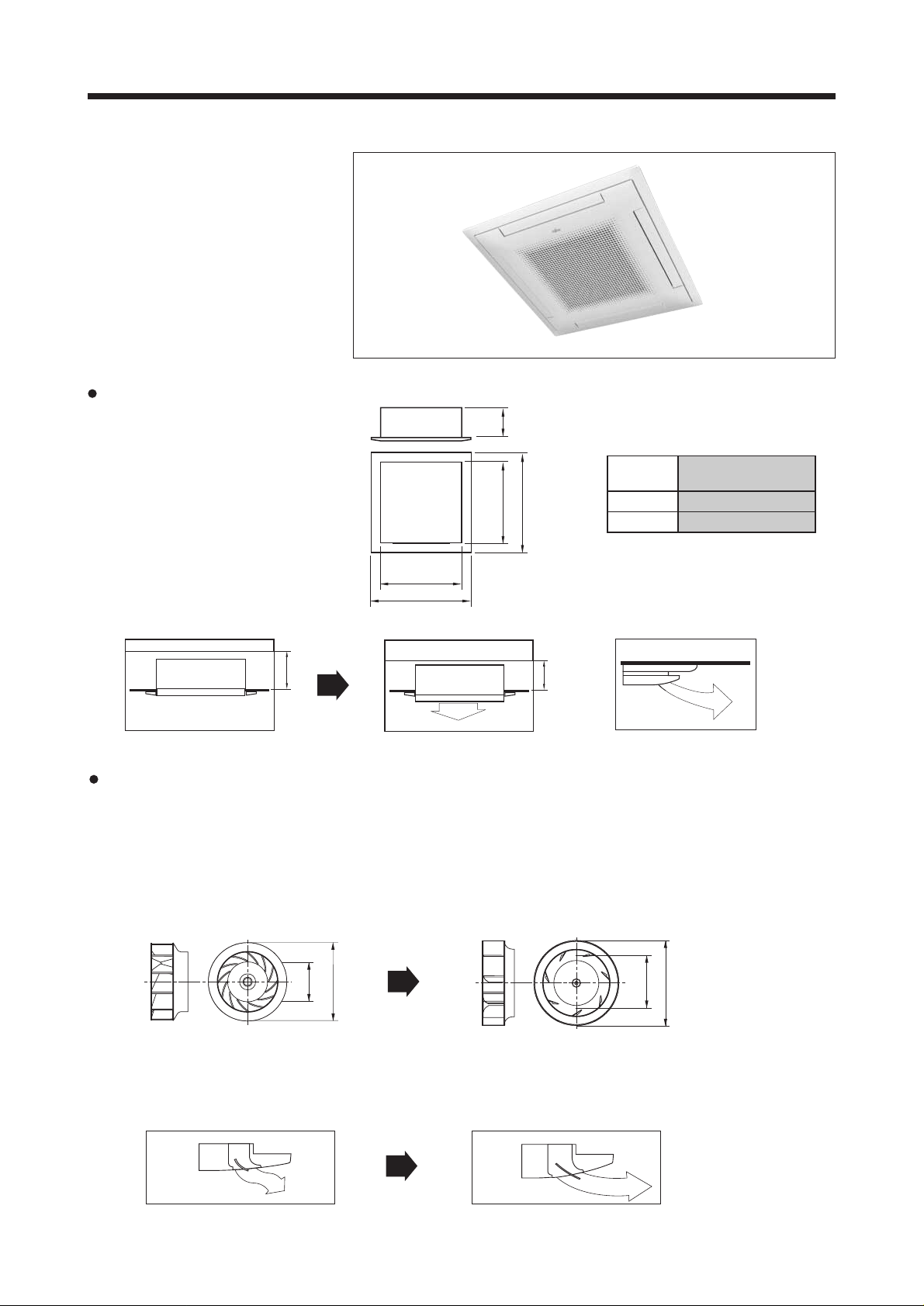
Flexible installation
Small and compact body
allows space saving installation
New mechanism allows the
cassette body to move 35mm
downward and contributes to keeping
the ceiling surface clean
Width
940
285 min.
Standard setting
Slender setting
Improvement of noise level and air distribution
Comparison of noise level (dB)
Noise level is drastically reduced by molded fan motor,
bigger caliber turbo-fan and larger air flow passage.
Height
940
Depth
250 min.
Height
Width
Depth
Setting space
250 or 285
840
840
Improvement of fan blade
Old fan (13 blades)
320
420
(Unit : mm)
Wide air flow
Larger air flap distributes the outlet air flow a longer distance in the horizontal direction
Old model
New fan (7 blades)
New model
– 2 –
350.5
(Unit : mm)
450
Page 4
2. OUTLINE AND DIMENSIONS
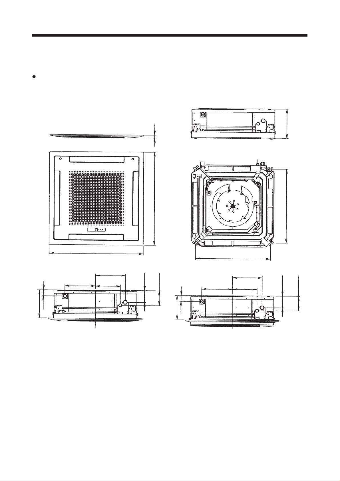
2.1 INDOOR UNIT
MODELS : AUY30A, AUY36A, AUY45A, AUY54A
AUY30R, AUY36R, AUY45R, AUY54R
(Unit : mm)
60
(Drain pipe)
305
940
298
248
30
940
120
(Large pipe)
150
(Small pipe)60(Drain pipe)
305
750
298
248
296
750
120
(Large pipe)
150
(Small pipe)
285
250
– 3 –
Page 5
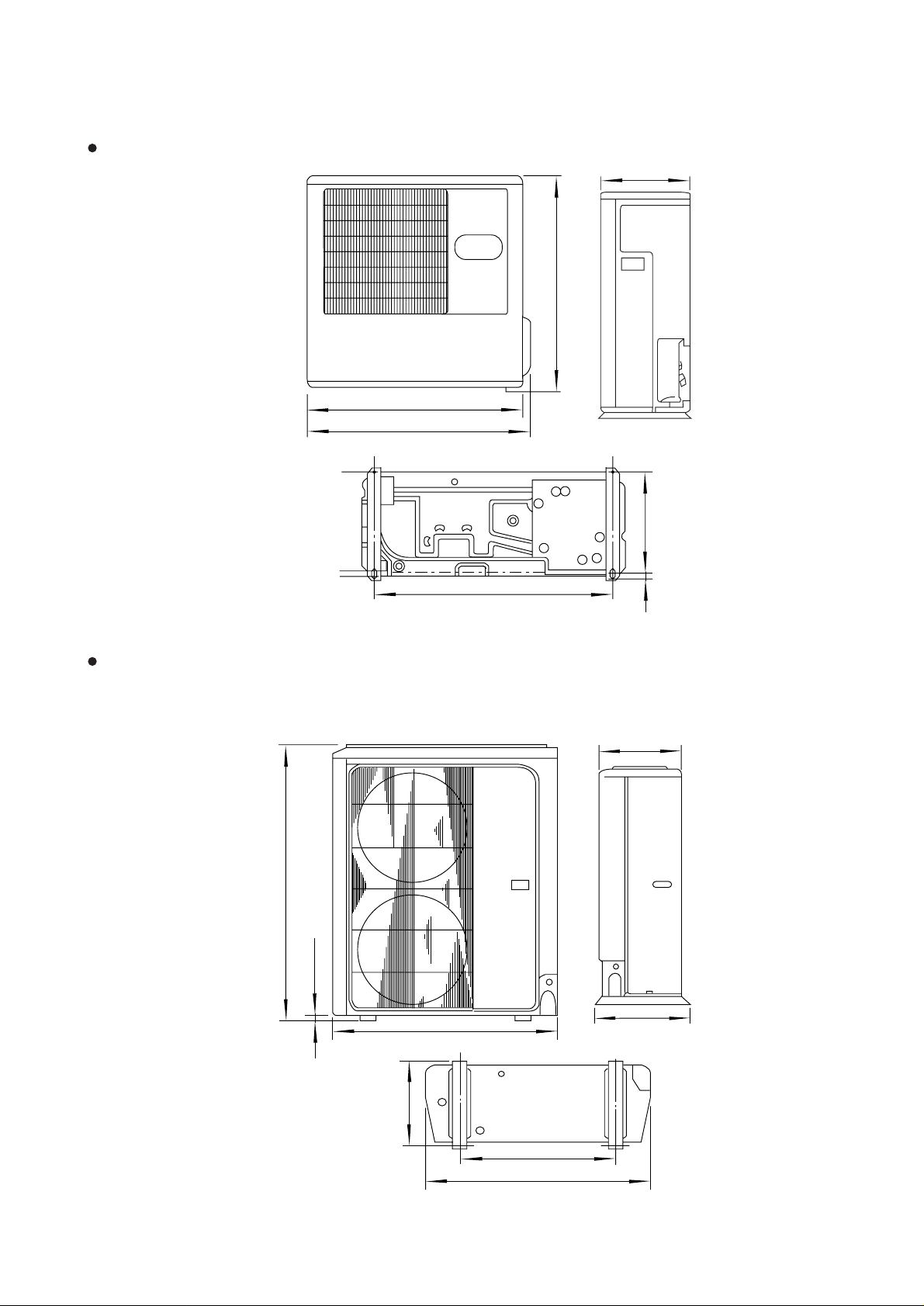
2.2 OUTDOOR UNIT
MODELS : AOY30A, AOY30R
(Unit : mm)
350
900
900
930
333
MODELS : AOY36A(3), AOY36R(3)
AOY45A(3), AOY45R(3)
AOY54A(3), AOY54R(3)
1,152
23
804
19
370
400
940
425
650
940
– 4 –
Page 6
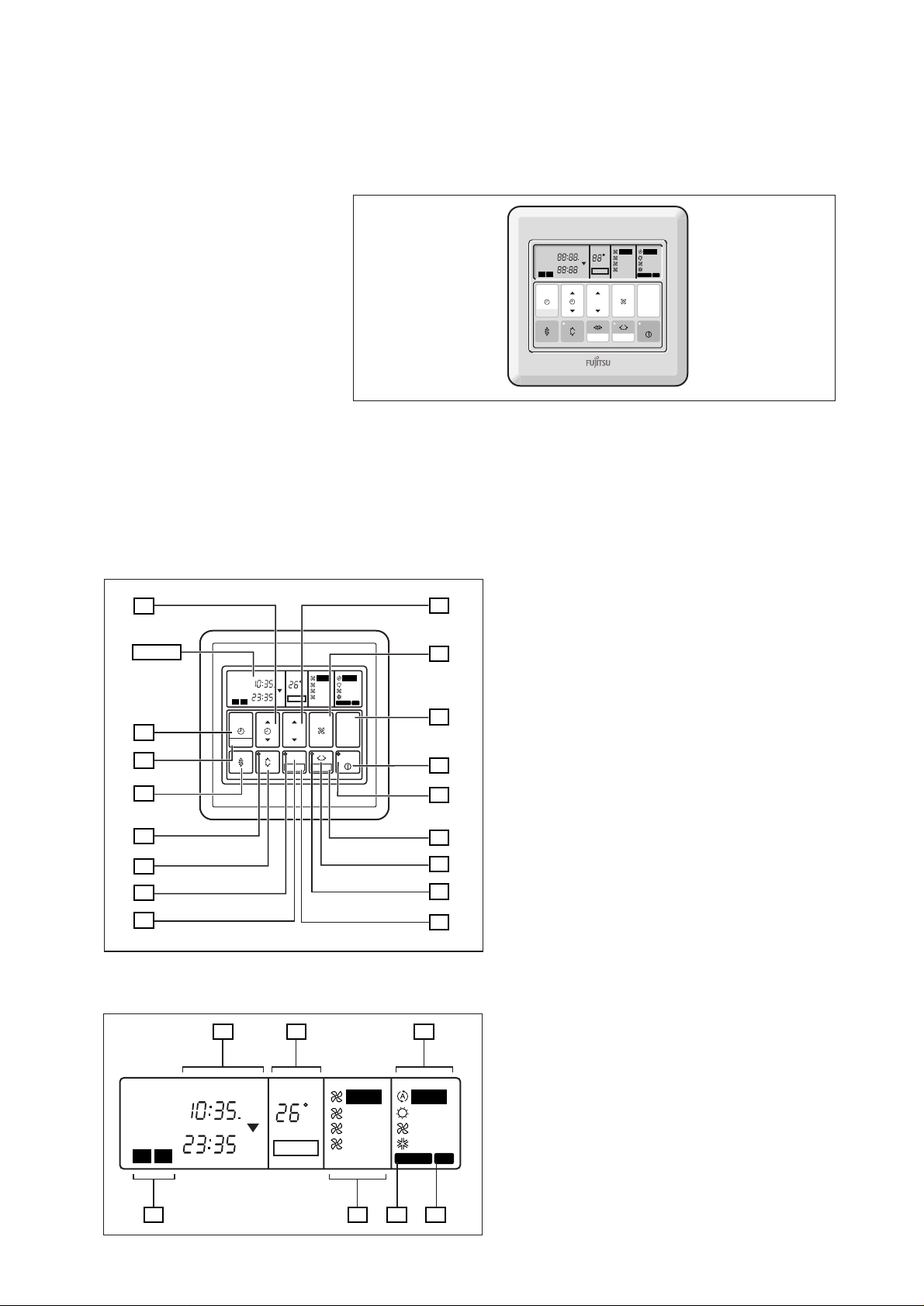
2.3 REMO TE CONTROLLER
WIRE REMOTE CONTROLLER WITH WEEKLY TIMER
CLOCK
NON STOP
OFFON
TIMER
WEEKLY
1
TIMER
MODE
CLOCK ADJUST
FEATURES
Three kinds of timer setup (OFF/ON/WEEKLY) are possible.
Function of weekly timer
Setting of different on-off time by day.
Setting of set on-off time twice a day.
Setting of time in 5 minute steps.
Timer operation of a reserved day can be temporarily cancelled by pushing the “DAY OFF” button.
Time setting can be left until the next day.
14
Display
CLOCK
TEMP.
AUTO
OFF
C
HIGH
ON
TIMER
2
NEXT DAY
SET TIME
ON
OFF
DAY OFF
TEMP./DAY
ZONE
SET
MED
DAY
LOW
FAN
CONTROL
DAY OFF
13
12
NON STOP
OFFON
TIMER
WEEKLY
1
TIMER
MODE
CLOCK ADJUST
11
10
9
8
7
Display panel
1918
NON STOP
CLOCK
OFFON
TIMER
TIMER
WEEKLY
2
1
NEXT DAY
21
OFF
ON
ON
OFF
TEMP.
C
DAY
DAY OFF
AUTO
HEAT
FAN
COOL
DEFROST TEST
MASTER
CONTROL
START/STOP
AUTO
HIGH
MED
LOW
15
16
17
20
AUTO
HEAT
FAN
COOL
DEFROST TEST
2322
24
1
2
3
4
5
6
– 5 –
1 START/STOP Button
Pressed to start and stop operation.
2 OPERATION Lamp
Lights during operation and when the timer is on.
3 DAY OFF Button
Temporary cancellation of one day timer.
4 ENERGY SAVE Button
Turns energy efficient mode on and off.
5 ENERGY SAVE Button
Lights up when the unit is in the energy save mode.
6 SET Button
Sets the date, hour minute and on-off time.
7 ZONE Button
Use to turn the zone control on and off.
8 ZONE Lamp
Lights up when the units is in the zone control mode.
9 VERTICAL SWING Button
10 VERTICAL SWING Lamp
11 VERTICAL AIR FLOW DIRECTION Button
12 CLOCK ADJUST Button
13 TIMER MODE Button
Changes the timer mode (NON STOP, OFF TIMER,
ON TIMER, WEEKL Y TIMER).
14 SET TIME Button
Sets the current time and on-off time.
15 TEMP./DAY Button
Sets the indoor temperature / days.
16 FAN CONTROL Button
Selects the fan speed (AUTO, HIGH, MED, LOW).
17 MASTER CONTROL Button
Selects the operating mode
(AUTO, HEAT, FAN, COOL).
18 Clock Display
19 Set Temperature / Day Display (TEMP./DAY)
20 Operation Mode Display
21 Timer Mode Display
22 Fan Speed Display
23 DEFROST Display
24 TEST Display
TEMP.
AUTO
OFF
C
HIGH
ON
TIMER
2
NEXT DAY
SET TIME
ON
OFF
DAY OFF
TEMP./DAY
SET
MED
DAY
LOW
FAN
CONTROL
DAY OFF
AUTO
HEAT
FAN
COOL
DEFROST TEST
MASTER
CONTROL
START/STOP
Page 7
3. DATA
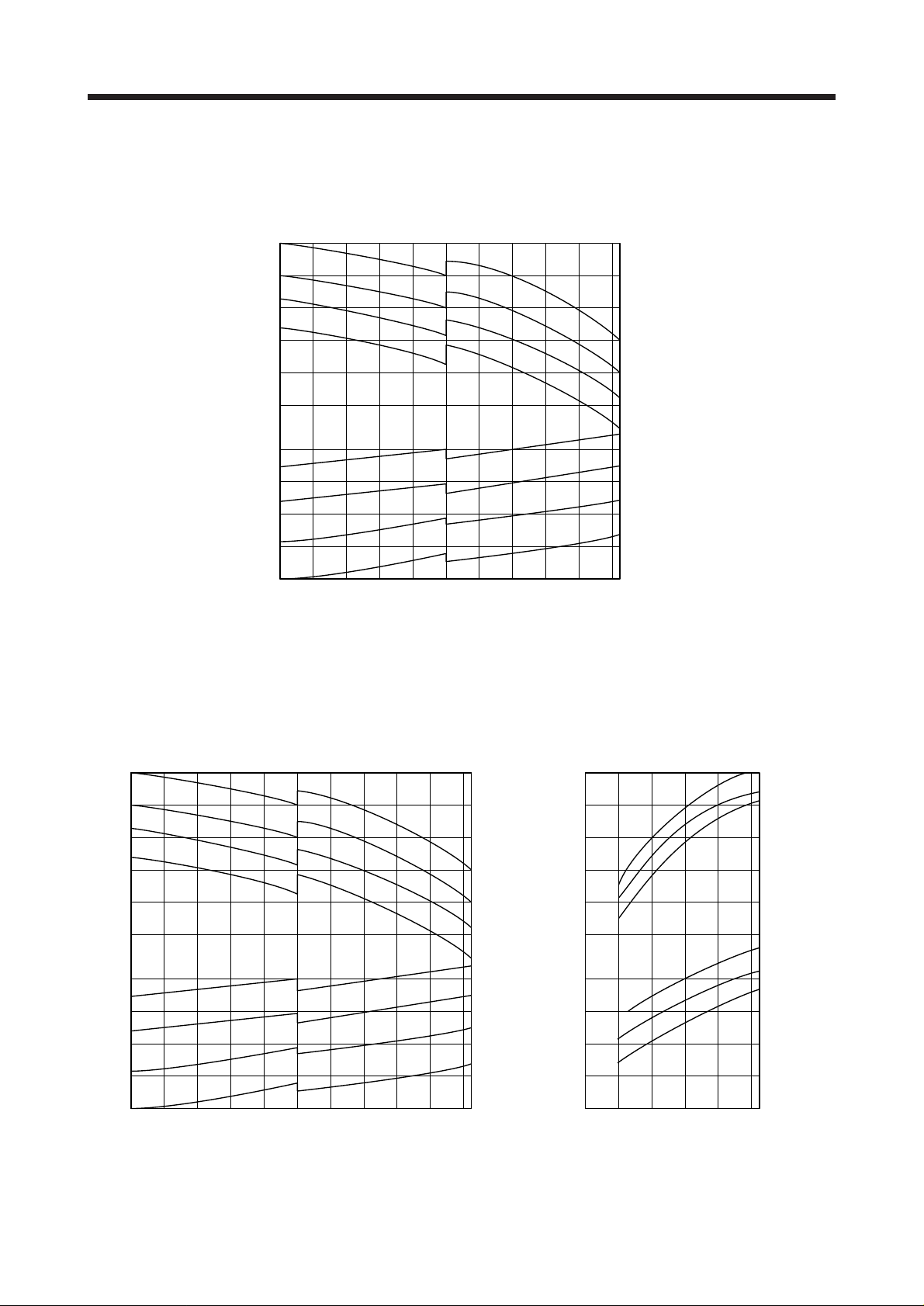
3.1 PERFORMANCE CURVE
AUY30A
Cooling
120
120
100
Capacity (%)
90
80
70
100
90
80
Total input (%)
0 5 10 15 20 25 30 35 40 45 50 52
Low ambient operation model
OUTDOOR DB (°C)
Indoor
DB/WB (°C)
31/22
27/19
23/16
31/22
19/12.5
27/19
23/16
19/12.5
AUY30R
Cooling
120
120
100
Capacity (%)
90
80
70
100
90
80
Total input (%)
0 5 10 15 20 25 30 35 40 45 50 52
Low ambient operation model
OUTDOOR DB (°C)
Indoor
DB/WB (°C)
31/22
27/19
23/16
19/12.5
31/22
27/19
23/16
19/12.5
120
120
100
Capacity (%)
90
80
70
100
90
80
Total input (%)
-5 0/-2 5/3
OUTDOOR DB/WB (°C)
Heating
10/9.5 15/12
15
20 21/
Indoor
DB (°C)
20
25
25
20
15
17.5
– 6 –
Page 8
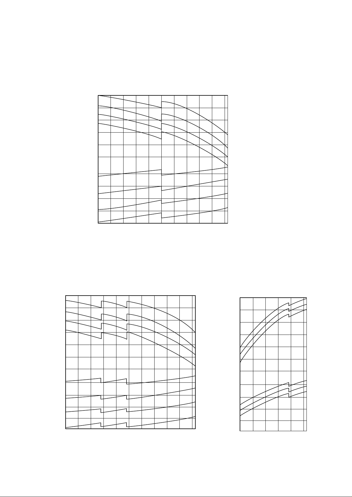
AUY36A, AUY45A, AUY54A
120
120
Cooling
100
Capacity (%)
90
80
70
100
90
80
Total input (%)
0 5 10 15 20 25 30 35 40 45 50 52
OUTDOOR DB (°C)
AUY36R, AUY45R, AUY54R
120
120
100
Capacity (%)
90
Cooling
Indoor
DB/WB (°C)
31/22.5
Indoor
DB/WB (°C)
31/22.5
27/19.0
23/16.5
19/13
31/22.5
27/19.5
23/16.5
19/13
120
120
100
Capacity (%)
90
Heating
Indoor
DB (°C)
15
20
25
80
70
100
90
Total input (%)
80
0 5 10 15 20 25 30 35 40 45 50 52
OUTDOOR DB (°C)
– 7 –
27/19.0
23/16.5
19/13
31/22.5
27/19.5
23/16.5
19/13
80
70
100
90
Total input (%)
80
-5/
-60/ -25/ 3
10/
15/
7.5
12
OUTDOOR DB/WB (°C)
25
24
15
20 21/
17.5
Page 9

3.2 TEMPERATURE RANGE
MODEL
AUY30A
AUY36A
AUY45A
AUY54A
AUY30R
AUY36R
AUY45R
AUY54R
Temperature Range
Indoor Unit Outdoor Unit
COOL 18°C to 32°C 00°C to 52°C
COOL 18°C to 32°C 00°C to 52°C
HEAT 30°C or less –5°C to 21°C
COOL 18°C to 32°C 00°C to 52°C
HEAT 30°C or less –8°C to 21°C
– 8 –
Page 10

3.3 ADDITIONAL REFRIGERANT CHARGE
PIPE LENGTH
AUY30A
AUY30R
AUY36A 2,300g(81.1oz)
FULL
CHARGE
AMOUNT
AUY36R 3,000g(10.6oz)
AUY45A 3,500g(123.5oz)
AUY45R 3,500g(123.5oz)
AUY54A 4,000g(141.1oz)
AUY54R 3,500g(123.5oz)
AUY30A, AUY30R
100
90
5m 10m 20m 25m 30m 40m 50m Additional
(16ft) (33ft) (66ft) (82ft) (99ft) (132ft) (164ft) refrigerant
2,350g
(82.9oz)
2,435g
(85.9oz)
2,605g
(91.9oz)
2,690g
2,850g
(100.5oz)
3,100g
(109.3oz)
3,600g
(127oz)
(94.9oz)
3,850g
(135.8oz)
2,500g
(88.2oz)
3,200g
(112.9oz)
3,700g
(130.5oz)
3,700g
(130.5oz)
4,250g
(149.9oz)
3,750g
(132.3oz)
Pipe size : Liquid 9.52 mm (3/8") Gas 15.88 mm (5/8")
2,775g
(97.9oz) ––– ––– 17g/m (0.6 oz)
4,100g
(144.6oz) ––– ––– 50g/m (1.76 oz)
2,700g
(95.2oz)
3100g
3,400g
3,900g
3,900g
4,500g
4,000g
(119.9oz)
(137.6oz)
(137.6oz)
(158.7oz)
(141.1oz)
(109.3oz)
3,800g
4,300g
4,300g
5,000g
4,500g
(134.0oz)
(151.7oz)
(151.7oz)
(176.4oz)
(158.7oz)
3,500g
(123.5oz) 40g/m
4,200g
(148.2oz) (1.41oz/3.3ft)
4,700g
(165.8oz)
4,700g
(165.8oz)
5,500g
(194.0oz) 50g/m
5,000g
(176.4oz) (1.76oz/3.3ft)
82%
Capacity (%)
80
70
5 101520253035
AUY36A, AUY45A, AUY54A
AUY36R, AUY45R, AUY54R
100
90
80
Capacity (%)
Connection pipe length (m)
Pipe size : Liquid 9.52 mm (3/8") Gas 19.05 mm (3/4")
Plotted under additional
refrigerant charge conditions.
85%
70
10 25 35 40 50
Connection pipe length (m)
Plotted under additional
refrigerant charge conditions.
– 9 –
Page 11

3.4 AIR VELOCITY DISTRIBUTION
AUY30A, AUY30R
4–WAY AIR OUTLET
(m)
3
2
1
0
0.25
1
2
3
8765432
(m)
2
1
0
87
0.25
UNIT : m/s
0.5
0.25
1
2
211 0.50.5 0.25
2
1
0.5
2
0.25
1012345678
UNIT : m/s
2
1
0.5
2
1
0.5
0.25
654321012345678
Note :
Condition
Fan speed : High
Operation mode : FAN
Voltage : 240V
TOP VIEW
AIR FLOW DIRECTION
: Upward
(m)
SIDE VIEW
AIR FLOW DIRECTION
: Upward
(m)
(m)
2
1
0
2–WAY AIR OUTLET
(m)
0.5 0.5
0.25 0.25
21012
1
0
1
87654321012345678
(m)
2
1
0
0.25
87654321012345678
UNIT : m/s
22
11
210.50.25 2 1 0.5 0.25
1
0.5
SIDE VIEW
AIR FLOW DIRECTION
: Downward
(m)
UNIT : m/s
TOP VIEW
AIR FLOW DIRECTION
: Upward
(m)
UNIT : m/s
2
2
1
0.5
0.25
SIDE VIEW
AIR FLOW DIRECTION
: Upward
(m)
– 10 –
Page 12

AUY36A, AUY36R
4–WAY AIR OUTLET
(m)
3
2
1
0
1
2
3
8765432
(m)
2
1
0
0.25
87
UNIT : m/s
0.5
0.25
1
2
210.50.25
2
1
0.5
2 1 0.5 0.25
0.25
1012345678
UNIT : m/s
2
1
0.5
2
1
0.5
0.25
654321012345678
Note :
Condition
Fan speed : High
Operation mode : FAN
Voltage : 240V
TOP VIEW
AIR FLOW DIRECTION
(m)
SIDE VIEW
AIR FLOW DIRECTION
(m)
(415)
: Upward
: Upward
(m)
2
1
0.5
0
2–WAY AIR OUTLET
(m)
0.25
21012
1
0
1
87654321012345678
(m)
2
1
0.25
0
87654321012345678
UNIT : m/s
2
1
0.5
2
1
0.5
0.25
210.50.25 2 1 0.5 0.25
2
1
SIDE VIEW
AIR FLOW DIRECTION
(m)
2
: Downward
1
0.5
UNIT : m/s
TOP VIEW
AIR FLOW DIRECTION
: Upward
(m)
UNIT : m/s
SIDE VIEW
AIR FLOW DIRECTION
: Upward
0.25
(m)
– 11 –
Page 13

AUY45A, AUY45R
4–WAY AIR OUTLET
(m)
3
2
1
0.25
0
1
2
3
8765432
(m)
2
1
0
0.25
87
UNIT : m/s
0.5
0.25
1
2
10.5
2
2
1
2 1 0.5 0.25
0.25
0.5
1012345678
UNIT : m/s
2
1
0.5
2
1
0.5
0.25
654321012345678
Note :
Condition
Fan speed : High
Operation mode : FAN
Voltage : 240V
TOP VIEW
AIR FLOW DIRECTION
(m)
SIDE VIEW
AIR FLOW DIRECTION
(m)
(415)
: Upward
: Upward
(m)
2
1
0.5
0
(m)
0.25
21012
2–WAY AIR OUTLET
1
0
1
87654321012345678
(m)
2
1
0.25
0
87654321012345678
UNIT : m/s
2
1
0.5
2
1
0.5
0.25
210.50.25 2 1 0.5 0.25
2
1
SIDE VIEW
AIR FLOW DIRECTION
(m)
2
: Downward
1
0.5
UNIT : m/s
TOP VIEW
AIR FLOW DIRECTION
: Upward
(m)
UNIT : m/s
SIDE VIEW
AIR FLOW DIRECTION
: Upward
0.25
(m)
– 12 –
Page 14

AUY54A, AUY54R
(m)
(m)
3
2
1
0.25
0
1
2
3
8765432
2
1
0.5
654321012345678 (m)
0
0.25
87
UNIT : m/s4–WAY AIR OUTLET
0.5
0.25
1
2
10.5
2
2 1 0.5 0.25
Note :
Condition
Fan speed : High
Operation mode : FAN
Voltage : 240V
(415)
TOP VIEW
AIR FLOW DIRECTION
: Upward
2
1
0.25
0.5
1012345678 (m)
UNIT : m/s
SIDE VIEW
2
1
2
1
0.5
0.25
AIR FLOW DIRECTION
: Upward
(m)
2
1
0
2–WAY AIR OUTLET
(m)
1
0.5
0.25
21012
1
0
0.25
1
87654321012345678
(m)
2
1
0.25
0
87654321012345678
2
0.5
2
1
1
UNIT : m/s
0.5
0.25
2
SIDE VIEW
AIR FLOW DIRECTION
: Downward
(m)
UNIT : m/s
TOP VIEW
AIR FLOW DIRECTION
210.5
2 1 0.5
: Upward
0.25
(m)
UNIT : m/s
SIDE VIEW
AIR FLOW DIRECTION
2
1
0.5
0.25
: Upward
(m)
– 13 –
Page 15

3.5 DUCT CONNECTION
OUTLET AIR
10
9
(mmAq)
(mmAq)
8
7
6
5
4
3
2
1
0
012345
10
9
8
7
6
5
4
3
2
1
0
0
240V Hi
220V Hi
220V Lo
Duct
(Inside Dia. ø100mm)
L
L=5m
240V Lo
240V Hi
220V Hi
240V Lo
220V Lo
12345
(m
(m
3
/min)
3
/min)
L=3m
L=1m
Duct
(Inside Dia. ø100mm)
L
L=5m
L=3m
L=1m
FRESH AIR
(mmAq)
Static pressure
required to take
in fresh air
Duct
(Inside Dia. ø70mm)
P
Duct Fan
7
6
5
4
3
2
1
0
0
0.1 0.2 0.3 0.4 0.5 0.6
– 14 –
(m
3
/min)
Page 16

3.6 REFRIGERANT SYSTEM DIAGRAM
Models : AUY30A / AOY30A
OUTDOOR UNIT INDOOR UNIT
Muffler
Dryer
Compressor
Capillary tube
Refrigerant pipe
ø 15.88mm(5/8")
Accumulator
Charging valve
EvaporatorCondenser
Refrigerant pipe
ø 9.53mm(3/8")
Models : AUY30R / AOY30R
OUTDOOR UNIT INDOOR UNIT
Pressure
check valve
Charging
valve
4-way
valve
Muffler
Compressor
Capillary
tube
Accumulator
Strainer
Refrigerant pipe
ø 15.88mm(5/8")
EvaporatorCondenser
Distributor
Dryer
Refrigerant pipe
ø 9.53mm(3/8")
: COOL
: HEAT
– 15 –
Page 17

Models : AUY36A / AOY36A
OUTDOOR UNIT INDOOR UNIT
Muffler
Dryer
Compressor
Capillary tube
Accumulator
Charging valve
Charging valve
Refrigerant pipe
ø 19.05mm(3/4")
EvaporatorCondenser
Refrigerant pipe
ø 9.53mm(3/8")
Models : AUY36R / AOY36R
OUTDOOR UNIT INDOOR UNIT
High
pressure
switch
4-way
valve
Muffler
Compressor
Charging
valve
Accumulator
Strainer
Refrigerant pipe
ø 19.05mm(3/4")
EvaporatorCondenser
Dryer
Expansion
valve
Charging valve
– 16 –
Refrigerant pipe
ø 9.53mm(3/8")
: COOL
: HEAT
Page 18

Models : AUY45A / AOY45A
AUY54A / AOY54A
OUTDOOR UNIT INDOOR UNIT
Muffler
Dryer
Compressor
Capillary tube
Accumulator
Charging valve
Charging valve
Refrigerant pipe
ø 19.05mm(3/4")
EvaporatorCondenser
Refrigerant pipe
ø 9.53mm(3/8")
Models : AUY45R / AOY45R
AUY54R / AOY54R
OUTDOOR UNIT INDOOR UNIT
High
pressure
switch
4-way
valve
Muffler
Compressor
Charging
valve
Accumulator
Strainer
Refrigerant pipe
ø 19.05mm(3/4")
EvaporatorCondenser
Dryer
Expansion
valve
Charging valve
– 17 –
Refrigerant pipe
ø 9.53mm(3/8")
: COOL
: HEAT
Page 19

3.7 NOISE LEVEL CHECK POINTS
INDOOR UNIT
1.5 m
OUTDOOR UNIT
1 m
AIR
h
h
2
– 18 –
Page 20

Old octave-band limiting frequencies, Hz
AUY30A, AUY30R
4,800
9,600
2,400
4,800
1,200
24,00
600
1,200
300
600
150
300
75
150
75
Below
1957 Noise Criteria
NC Curves
NC-65
NC-60
NC-55
NC-50
NC-45
NC-40
NC-35
NC-30
NC-25
NC-20
NC-15
New octave-band center frequencies, Hz
63 125 250 500 1,000 2,000 4,000 8,000
4,800
9,600
2,400
4,800
1,200
24,00
600
1,200
300
600
80
70
1957 Noise Criteria
NC Curves
NC-65
60
Octave-band sound-pressure level dB: (0dB=0.0002µbar)
NC-55
NC-60
50
NC-50
NC-45
40
NC-40
NC-35
30
NC-30
NC-25
20
NC-20
10
NC-15
0
AUY36A, AUY36R
Old octave-band limiting frequencies, Hz
150
75
Below
300
150
75
80
70
60
Octave-band sound-pressure level dB: (0dB=0.0002µbar)
50
40
30
– 19 –
20
10
New octave-band center frequencies, Hz
63 125 250 500 1,000 2,000 4,000 8,000
0
Page 21

4,800
9,600
2,400
4,800
1,200
24,00
600
1,200
300
600
1957 Noise Criteria
NC Curves
NC-65
NC-60
NC-55
NC-50
NC-45
NC-40
NC-35
NC-30
NC-25
NC-20
NC-15
AUY45A, AUY45R
Old octave-band limiting frequencies, Hz
150
300
75
150
75
Below
4,800
9,600
2,400
4,800
1,200
24,00
80
New octave-band center frequencies, Hz
63 125 250 500 1,000 2,000 4,000 8,000
70
1957 Noise Criteria
NC Curves
NC-65
60
Octave-band sound-pressure level dB: (0dB=0.0002µbar)
NC-55
NC-60
50
NC-50
NC-45
40
NC-40
NC-35
30
NC-30
NC-25
20
NC-20
10
NC-15
0
AUY54A, AUY54R
Old octave-band limiting frequencies, Hz
600
300
150
75
Below
1,200
600
300
150
75
80
70
60
Octave-band sound-pressure level dB: (0dB=0.0002µbar)
50
40
30
– 20 –
20
10
New octave-band center frequencies, Hz
63 125 250 500 1,000 2,000 4,000 8,000
0
Page 22

4,800
9,600
2,400
4,800
1,200
24,00
600
1,200
300
600
1957 Noise Criteria
NC Curves
NC-65
NC-60
NC-55
NC-50
NC-45
NC-40
NC-35
NC-30
NC-25
NC-20
NC-15
AOY30A, AOY30R
Old octave-band limiting frequencies, Hz
150
300
75
150
75
Below
4,800
9,600
2,400
4,800
1,200
24,00
80
New octave-band center frequencies, Hz
63 125 250 500 1,000 2,000 4,000 8,000
70
1957 Noise Criteria
NC Curves
NC-65
60
Octave-band sound-pressure level dB: (0dB=0.0002µbar)
NC-55
NC-60
50
NC-50
NC-45
40
NC-40
NC-35
30
NC-30
NC-25
20
NC-20
10
NC-15
0
AOY36A, AOY36R
Old octave-band limiting frequencies, Hz
600
300
150
75
Below
1,200
600
300
150
75
80
70
60
Octave-band sound-pressure level dB: (0dB=0.0002µbar)
50
40
30
– 21 –
20
10
New octave-band center frequencies, Hz
63 125 250 500 1,000 2,000 4,000 8,000
0
Page 23

AOY45A, AOY45R
Old octave-band limiting frequencies, Hz
4,800
9,600
2,400
4,800
1,200
24,00
600
1,200
300
600
150
300
75
150
75
Below
1957 Noise Criteria
NC Curves
NC-65
NC-60
NC-55
NC-50
NC-45
NC-40
NC-35
NC-30
NC-25
NC-20
NC-15
New octave-band center frequencies, Hz
63 125 250 500 1,000 2,000 4,000 8,000
4,800
9,600
2,400
4,800
1,200
24,00
600
1,200
300
600
80
70
1957 Noise Criteria
NC Curves
NC-65
60
Octave-band sound-pressure level dB: (0dB=0.0002µbar)
NC-55
NC-60
50
NC-50
NC-45
40
NC-40
NC-35
30
NC-30
NC-25
20
NC-20
10
NC-15
0
AOY54A, AOY54R
Old octave-band limiting frequencies, Hz
150
75
Below
300
150
75
80
70
60
Octave-band sound-pressure level dB: (0dB=0.0002µbar)
50
40
30
– 22 –
20
10
New octave-band center frequencies, Hz
63 125 250 500 1,000 2,000 4,000 8,000
0
Page 24

4. SPECIFICATIONS
TYPE COOLING TYPE COOLING & HEATING TYPE
MODEL
POWER SOURCE V/ /Hz 220-240/1/50 380-415/3/50 380-415/3/50 380-415/3/50 220-240/1/50 380-415/3/50 380-415/3/50 380-415/3/50
COOLING CAPACITY kW 8.6 - 8.8 10.3 - 10.5 12.4 - 12.7 13.9 - 14.1 8.6 - 8.8 10.3 - 10.5 12.4 - 12.7 13.9 - 14.1
HEATING CAPACITY kW ––– ––– ––– ––– 8.8 - 9.1 10.5 - 10.7 13.4 - 13.7 15.4 - 15.8
RUNNING CURRENT (A)
INPUT WATTS (kW)
STARTING CURRENT A 80 42 55 79 80 42 55 79
MOISTURE REMOVAL /h4566456 6
E.E.R. (kW/kW)
FAN SPEED (r.p.m.)
IN AUY30ALB-W AUY36ALA3W AUY45ALA3W AUY54ALA3W AUY30RLB-W AUY36RLA3W AUY45RLA3W AUY54RLA3W
OUT AOY30ABKL AOY36ACF3L AOY45ACF3L AOY54ABF3L AOY30RBJL AOY36RCF3L AOY45RCF3L AOY54RBF3L
COOLING 15.8-16.3 6.6 - 6.6 7.5 - 7.5 8.5 - 8.6 16.0 - 16.5 6.6 - 6.6 7.5 - 7.5 8.5 - 8.6
HEATING ––– ––– ––– ––– 14.1 - 14.6 5.9 - 5.9 7.5 - 7.5 8.5 - 8.6
COOLING 3.30 - 3.40 3.73 - 3.80 4.35 - 4.45 4.90 - 5.00 3.35 - 3.45 3.88 - 3.95 4.35 - 4.45 4.90 - 5.00
HEATING ––– ––– ––– ––– 2.90 - 3.00 3.40 - 3.45 4.25 - 4.35 4.85 - 4.90
COOLING 2.61 - 2.59 2.76 - 2.76 2.85 - 2.85 2.84 - 2.82 2.57 - 2.55 2.65 - 2.66 2.85 - 2.85 2.84 - 2.82
HEATING ––– ––– ––– ––– 3.03 - 3.03 3.09 - 3.10 3.15 - 3.15 3.18 - 3.22
HIGH 500 580 620 680 500 580 620 680
MED 430 500 550 580 430 500 550 580
LOW 360 420 470 500 360 420 470 500
OUTER 730 790 790 790 760 790 790 790
AIR FLOW
NOISE LEVEL
(dB[A])
DIMENSIONS
H x W x D OUT
(mm)
WEIGHTS
[NET/GROSS] (kg)
MAXIMUM PIPE LENGTH / HEIGHT 30 / 15 50 / 30 30 / 15 50 / 30
REMOTE CONTROLLER TYPE WIRED
INDOOR
OUTDOOR 3,320 5,900 5,500 5,500 3,450 5,900 5,500 5,500
INDOOR MED 42 44 46 48 42 44 46 48
OUTDOOR 54.5 57.5 59 59 56 58 59 59
NET GRILLE
GROSS IN
m3/h
HIGH 45 48 49 52 45 48 49 52
LOW 39 39 42 44 39 39 42 44
IN
OUT
IN 47 / 60
OUT 85 / 97 94 / 108 102 / 116 112 / 126 85 / 97 96 /110 108 / 122 120 /134
1,300 1,500 1,650 1,800 1,300 1,500 1,650 1,800
296 x 830 x 830
35 x 940 x 940
900 x 900 x 350 1,152 x 940 x 370 900 x 900 x 350 1,152 x 940 x 370
455 x 1,060 x 1,025
1,045 x 1,025 x 445
1,280 x 1,000 x 450 1,045x1,025x445 1,280 x 1,000 x 450
– 23 –
Page 25

MEMO
– 24 –
Page 26

1116, Suenaga, Takatsu-ku, Kawasaki 213-8502, Japan
0006J-901-1699 June 2000 Printed in Japan
 Loading...