

Page 1

CASSETTE TYPE AIR CONDITIONER
TECHNICAL MANUAL
FUJITSU GENERAL LIMITED
Page 2

BACK
NEXT
CASSETTE TYPE AIR CONDITIONER
1. FEATURES AND OPERATION
2. SPECIFICATIONS
3. OUTLINES AND DIMENSIONS
4. D ATA
5. REFRIGERANT SYSTEM DIAGRAM
6. CIRCUIT DIAGRAM
7. NOISE LEVEL MEASUREMENT
8. PRECAUTIONS ON INSTALLATION
9. TROUBLESHOOTING
10. OPTIONAL PARTS
Page 3

BACK
NEXT
1 FEATURES AND OPERATION
1.1 MODEL IDENTIFICATION
1.2 APPLICATION MODEL
1.3 FEATURES OF EACH MODEL
1.4 EASY OPERATION BY REMOTE CONTROLLER
1.4.1 WIRELESS TYPE CONTROL FUNCTIONS
1.4.2 LCD WIRED TYPE CONTROL FUNCTIONS
2 SPECIFICATIONS
2.1 AU18, 18R, 25, 25R, 30, 30R (1-PHASE 50Hz)
2.2 AU25, 36, 36R, 45, 45R (3-PHASE 50Hz)
2.3 AU25, 25R, 36, 36R (1-PHASE 60Hz)/AU45, 45R (3-PHASE 60Hz)
3 OUTLINES AND DIMENSIONS
3.1 GRILLE
3.2 INDOOR UNIT FOR AU18, 18R, 25, 25R
3.3 INDOOR UNIT FOR AU30, 30R, 36, 36R, 45, 45R
3.4 OUTDOOR UNIT FOR AO18, 18R, 25, 25R, 25(3)
3.5 OUTDOOR UNIT FOR AO30, 30R, 36, 36R, 45, 45R
4 D ATA
4.1 PERFORMANCE CURVE
4.1.1 AU18, 25
4.1.2 AU25(3)
4.1.3 AU18R,25R
4.1.4 AU30, 36, 45(3)
4.1.5 AU30R, 36R, 45R(3)
4.1.6 PIPE LENGTH FOR AU18, 18R, 25, 25R, 25(3), 30, 30R
4.1.7 PIPE LENGTH FOR AU36, 36R, 45(3), 45R(3)
4.2 TEMPERATURE RANGE
4.3 REFRIGERANT CHARGING
4.4 AIR VELOCITY DISTRIBUTION
4.4.1 AU18
4.4.2 AU25
4.4.3 AU30
4.4.4 AU36
4.4.5 AU45
4.5 DUCT CONNECTION
4.5.1 OUTLET AIR FOR AU30, 30R, 36(3), 36R(3), 45(3),45R(3)
4.5.2 FRESH AIR FOR AU30, 30R, 36(3), 36R(3), 45(3),45R(3)
Page 4

BACK
NEXT
5 REFRIGERANT SYSTEM DIAGRAM
5.1 AU18/AO18
5.2 AU18R/AO18R
5.3 AU25/AO25, AU25(3)/ AO25(3)
5.4 AU25R/AO25R
5.5 AU30/AO30
5.6 AU30R/AO30R
5.7 AU36/AO36
5.8 AU36R/AO36R (50Hz)
5.9 AU36R/AO36R (60Hz)
5.10 AU45/AO45
5.11 AU45R/AO45R
6 CIRCUIT DIAGRAM
6.1 OVERALL CIRCUIT DIAGRAM
6.1.1 AU18/AO18, AU25/AO25 (Inside power supply)
6.1.2 AU18/AO18, AU25/AO25 (Outside power supply)
6.1.3 AU25(3)/AO25(3) (Low ambient cooling model)
6.1.4 AU18R/AO18R, AU25R/AO25R
6.1.5 AU30/AO30 (Low ambient cooling model)
6.1.6 AU30R/AO30R
6.1.7 AU36/AO36, AU45/AO45 (50Hz)
6.1.8 AU36/AO36, AU45/AO45 (50Hz) (Low ambient cooling model)
6.1.9 AU36/AO36R, AU45R/AO45R (50Hz)
6.2 INDOOR PRINTED CIRCUIT BOARD CIRCUIT DIAGRAM
6.2.1 AU18, 25 (Inside power supply)
6.2.2 AU18, 25, 30, 36, 45
6.2.3 AU18R, 25R, 30R, 36R, 45R
6.3 OUTDOOR PRINTED CIRCUIT BOARD CIRCUIT DIAGRAM
6.3.1 AO18R, 25R
6.3.2 AO30R
6.3.3 AO36R, 45R (50Hz)
6.4 WIRELESS REMOTE CONTROLLER CIRCUIT DIAGRAM
6.5 LIQUID CRYSTAL WIRED REMOTE CONTROLLER CIRCUIT DIAGRAM
7 NOISE LEVEL MEASUREMENT
7.1 NOISE LEVEL CHECK POINTS
7.2 NOISE LEVEL CURVE
Page 5

BACK
NEXT
8 PRECAUTIONS ON INSTALLATION
8.1 INSTALLAITION MANUAL
8.1.1 AU18, 25, 25(3)
8.1.2 AU18R, 25R
8.1.3 AU30, 36, 45 (50Hz)
8.1.4 AU30R, 36R, 45R (50Hz)
8.1.5 AU36R, 45R (60Hz)
8.1.6 AU36R, 45R (60Hz)
8.2 LIQUID CRYSTAL WIRED REMOTE CONTROL INSTALLATION
9 TROUBLESHOOTING
9.1 WIRELESS REMOTE CONTROL MODEL
9.2 LIQUID CRYSTAL WIRED REMOTE CONTROL MODEL
9.3 CARE AND MAINTENANCE
10 OPTIONAL PARTS
10.1 WIRELESS REMOTE CONTROL MODEL
10.2 LIQUID CRYSTAL WIRED REMOTE CONTROL MODEL
Page 6
BACK
NEXT
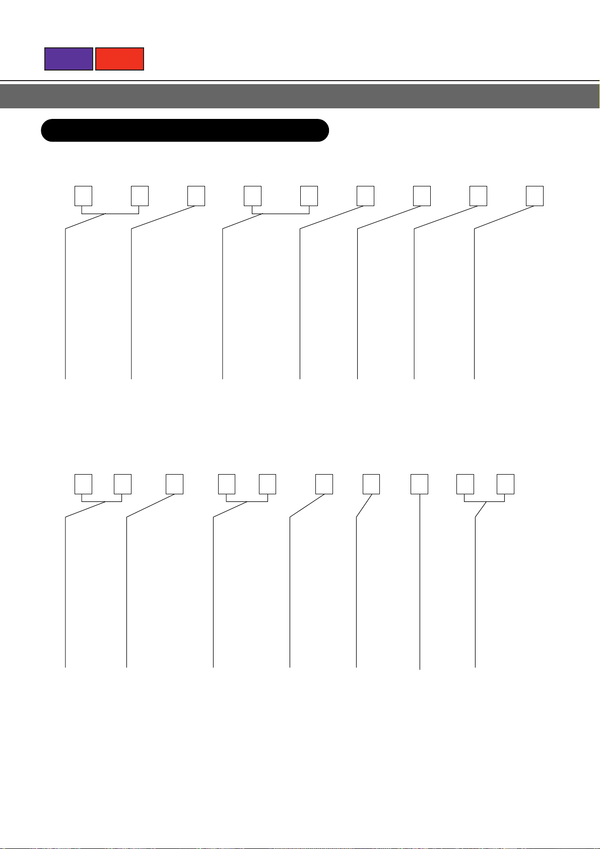
1.1 MODEL IDENTIFICATION
INDOOR UNIT
1
A
TYPE
AU: CASSETE
OUTDOOR UNIT
1
2 10
2
U
DESTINATION
MARKET REGIONS
T: 50Hz FUJITSU
(AUSTRALIA)
Y: 50Hz FUJITSU
3
T
3
4
1
CAPACITY RANK
BTU/h
18: 18000
24: 24000
25: 25000
30: 30000
36: 36000
45: 45000
4
5
5
8
FUNCTION
TYPE
R: REVERSE
CYCLE
A: COOLING
ONLY
6
6
A
CONTROL
METHOD
(REMOTE
CONTROL)
L: WIRED
S: WIRELESS
78L9
7
S
SHOWING
MINOR
CHANGES
8
C
SPECIAL
METHOD
3: 3-PHASE
9
3
A
TYPE
AO: OUT-
DOOR
O
DESTINATION
MARKET REGIONS
T: 50Hz FUJITSU
(AUSTRALIA)
Y: 50Hz FUJITSU
T
1
CAPACITY RANK
BTU/h
18: 18000
24: 24000
25: 25000
30: 30000
36: 36000
45: 45000
8
A
FUNCTION
TYPE
R: REVERSE
CYCLE
A: COOLING
ONLY
W
SHOWING
COMPRESSOR
USED
A
SHOWING
MINOR
CHANGES
SPECIAL
METHOD
FUNCTION
3: 3-PHASE
L: LOW AMBIENT
TEMPERATURE
COOLING
OPERATION
Page 7
BACK
NEXT
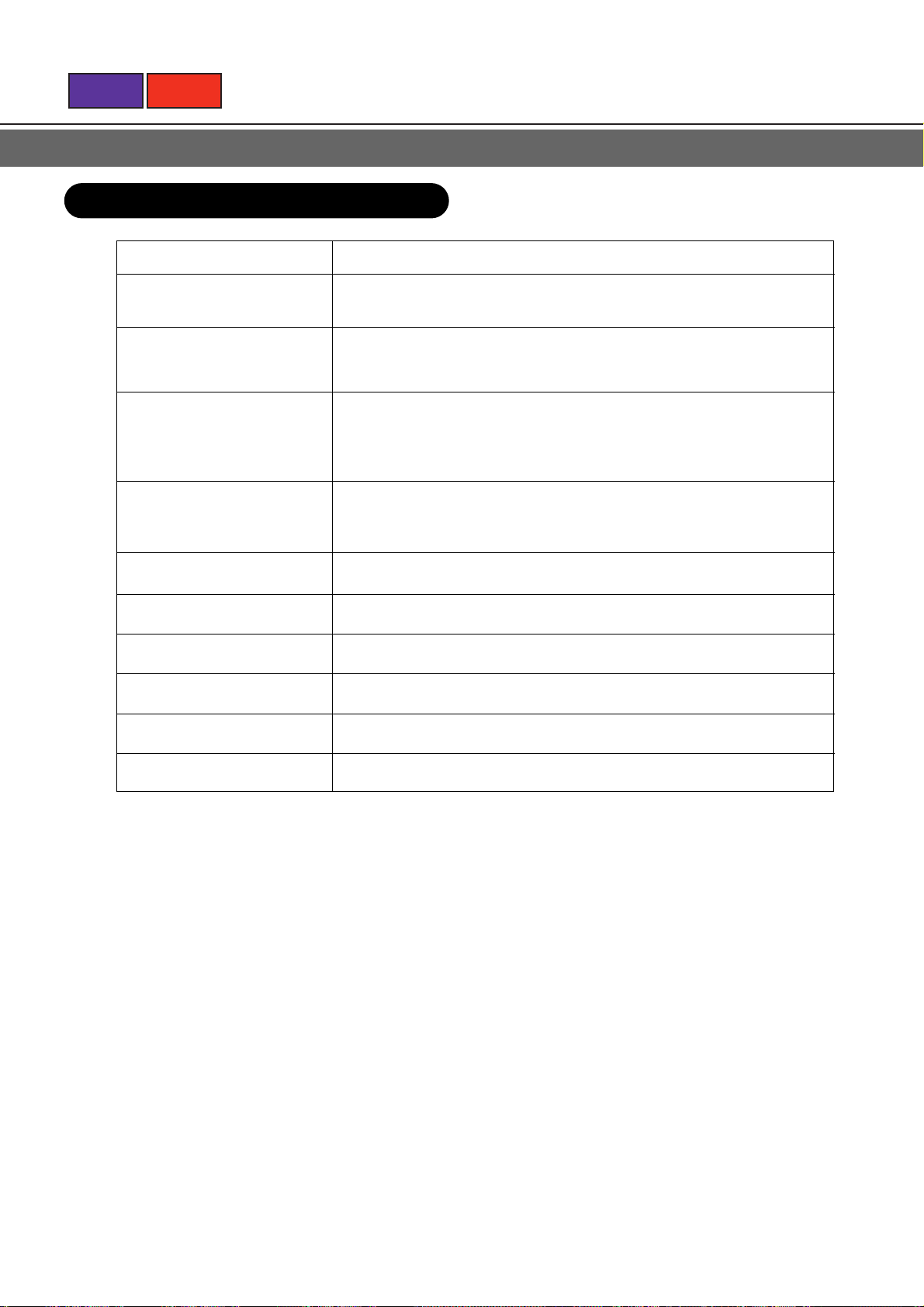
1.2 APPLICATION MODEL
TYPE MODEL NAME
AU18/AO18 AUY18ASC/AOY18AWA AUY18ASD/AOY18AWDL
AU18R/AO18R AUT18RLC/AOT18RWBL AUY18RLC/AOY18RWBL
AU25/AO25 AUT25ASC/AOT25AWA AUY25ASC3/AOY25ACA3L
AUY25ASC/AOY25AWA AUY25ASD3/AOY25ACD3L
AUY25ASD/AOY25AWDL
AU25R/AO25R AUT25RLC/AOT25RWDL AUY25RLD/AOY25RWDL
AUY25RLC/AOY25RWDL
AUY18RLD/AOY18RWDL
AU30/AO30 AUY30ASC/AOY30ABAL
AU30R/AO30R AUY30RLC/AOY30RBFL
AU36/AO36 AUY36ASC3/AOY36ACA3L AUT36ASC3/AOT36ACA3
AU36R/AO36R AUT36RLC3/AOT36RCB3L AUY36RLC3/AOY36RCB3L
AU45/AO45 AUY45ASC3/AOY45ACA3L AUT45ASC3/AOT45ACA3
AU45R/AO45R AUT45RLC3/AOT45RCB3L AUY45RLC3/AOY45RCB3L
Page 8
BACK
NEXT
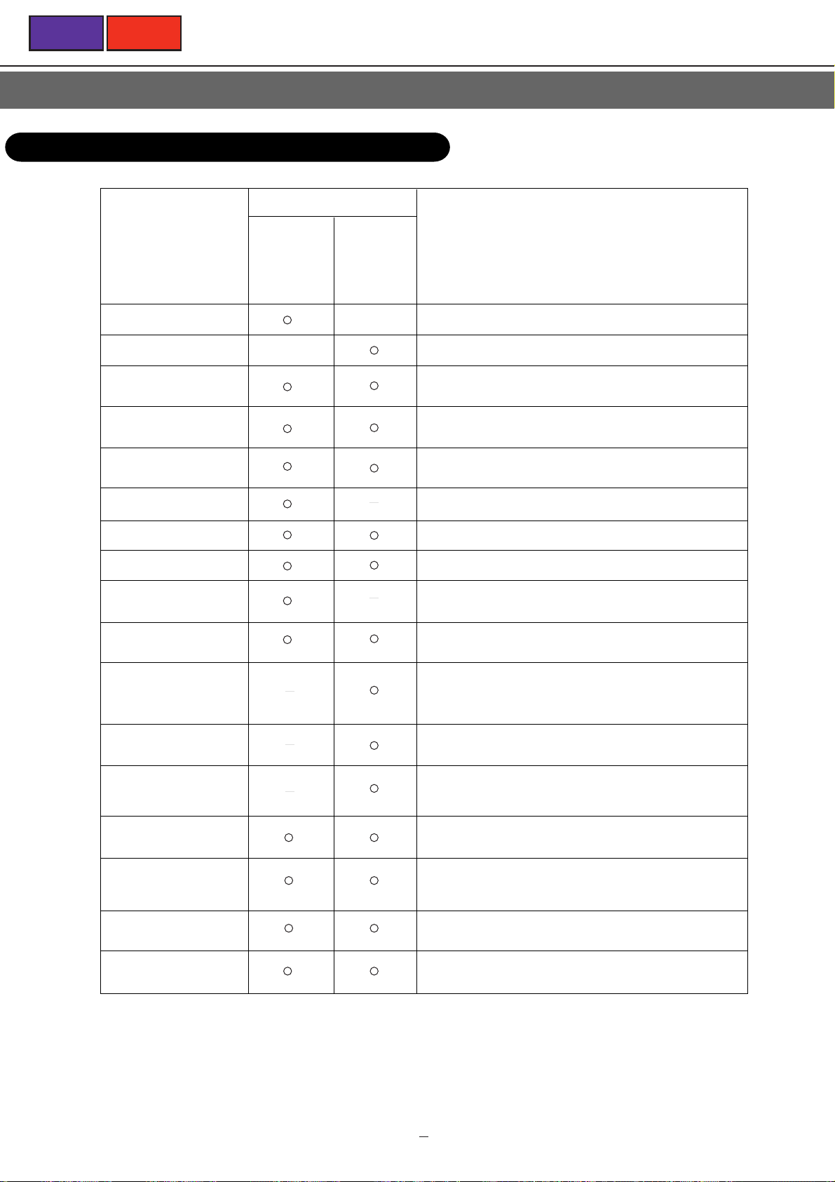
1.3 FEATURES OF EACH MODEL
Cassette type
AU18 AU18R
AU25 AU25R
AU25(3) AU30R
AU30 AU36R(3)
AU36(3) AU45R(3)
AU45(3)
Wireless remote
controller
Liquid crystal wired
remote controller
Auto restart
Auto louver
Auto fan speed
Dry
Off timer
On timer
Sleep
Program timer
Repeat timer
Zone control
Energy save
Simultaneous 16 air
conditioners control
Twin remote control
Auto change
Low ambient operation
( )
Function
Refer to the item 1.4.1 on page XX.
Refer to the item 1.4.2 on page XX.
In the event of a temporary power failure, the air conditioner
will automatically restart in the same operating mode as
before, once the power supply is restored.
The louver automatically swings to right and left. The
direction and the angle of the air flow can be easily
changed.
The optimum fan speed is available with the difference
between the indoor temperature and the setting
temperature.
The computer effectively dehumidifies the air.
(Air conditioner will operate with gentle cooling operation.)
When the timer reaches the set time, the air conditioner will
be turned off.
When the timer reaches the set time, the air conditioner will
be started.
The microcomputer gradually changes the room
temperature automatically to afford a comfortable night's
sleep.
Combines the OFF timer and the ON timer for one cycle.
(OFF
Æ ON or ON Æ OFF) Starts operation from the OFF
timer or ON timer, whichever is closer to the current time.
Combines the operation of the OFF timer and ON timer (the
cycle described in the PROGRAM timer above) so they
repeat the same cycle every day. Starts operation from the
OFF timer or ON timer, whichever is closer to the current
time.
When the ZONE CONTROL button is pressed while multiple
air conditioners are being centralized controlled, only the
preset air conditioners stop.
The energy conservation mode (ENERGY SAVE) raises the
set temperature slightly in the cooling mode and lowers the
set temperature in the heating mode, using a computer
program to economically control the operation of the unit.
One remote controller can control up to 16 air conditioners.
All the air conditioners can be operated with the same
setting.
Two remote controllers can be connected to one air
conditioner unit. The air conditioner operation contents are
the remote controller setting contents set later. (Both remote
controllers show the same display.)
In the auto mode, the air conditioner switches automatically
between cooling and heating, keeping the room at or around
the set temperature.
Cooling capacity is variable over a wide range, so the inside
environment stays comfortable with very little variation in
temperature or humidity.
NOTE: The parenthesis ( ) shows that the function is installed or not according to models.
1 3
Page 9
BACK
NEXT
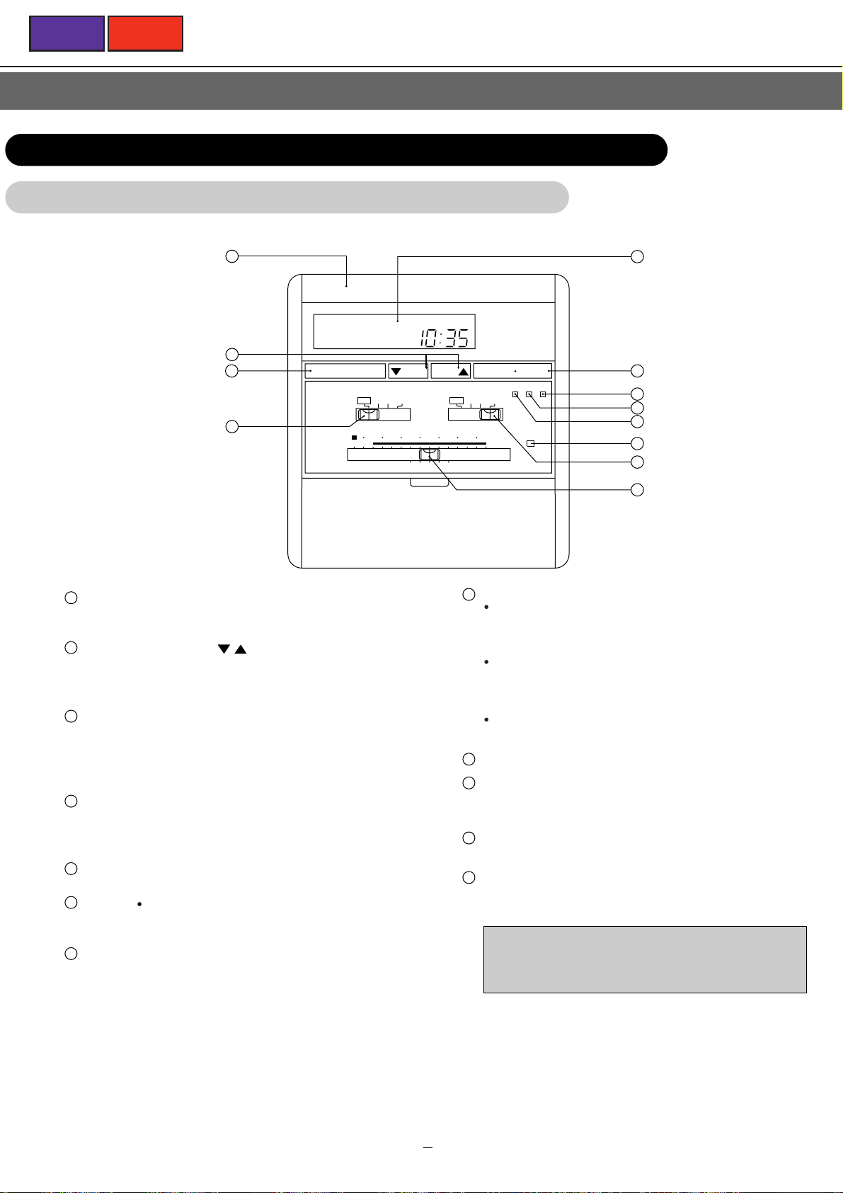
1.4 EASY OPERATION BY REMOTE CONTROLLER
1.4.1 WIRELESS REMOTE CONTROLLER
1
NON STOP CLOCK
2
1
Signal Transmitter
3
4
TIMER SET
AUTO AUTO
MASTER
CONTROL
THRTMOSTAT
Transmits control signals to the air conditioner.
2
SET TIME Buttons
/
( )
Use to make timer settings, to change the time, and to
set the clock to the current time.
3
TIMER Button
Use to select the various timer modes(OFF timer, ON
timer, PROGRAM timer, SLEEP timer, NON-STOP
operation).
4
MASTER CONTROL Switch
Use to select the various operating modes (AUTO,
COOL, DRY, FAN).
5
Remote Control Unit Display (LCD)
6
START
STOP Button
Press to start and stop operation.
7
ACL Button
5
6
7
8
9
10
11
LOW MED
26
28
START STOP
TIME ADJUST
TEST RUN
HIGH
LOUVER
30
ACL
TIME
COOL
DRY
FAN
FAN
CONTROL
18
20
22
24
19 21 23 25 27
12
8
TEST RUN Button
This button is used when installing the air conditioner,
and should not be used under normal conditions,
since it will cause the air conditioner's thermostat
function to stop operating properly.
If this button is pressed during normal operation, the
unit will switch to test operation mode, and the room
unit's operation lamp and timer lamp will begin to flash
simultaneously.
To stop the test operation mode, press the Operation
Stop button to stop the air conditioner.
9
TIME ADUST Button
10
LOUVER Button
Press it start and stop auto louver operation.
Press it to turn on and press again to turn off.
11
FAN CONTROL Switch
Use to select the fan speed (AUTO, LOW, MED,HIGH).
12
THERMOSTAT Control Switch
Use to set the desired room temperature.
Depending on the conditions in your room, the
displayed temperature may differ from the actual room
temperature.
1 4
Page 10
BACK
TIMER SET
TIME
START STOP
NON STOP CLOCK
SLEEP
TIMER
PROGRAM
OFF ON
1
2
3
NEXT
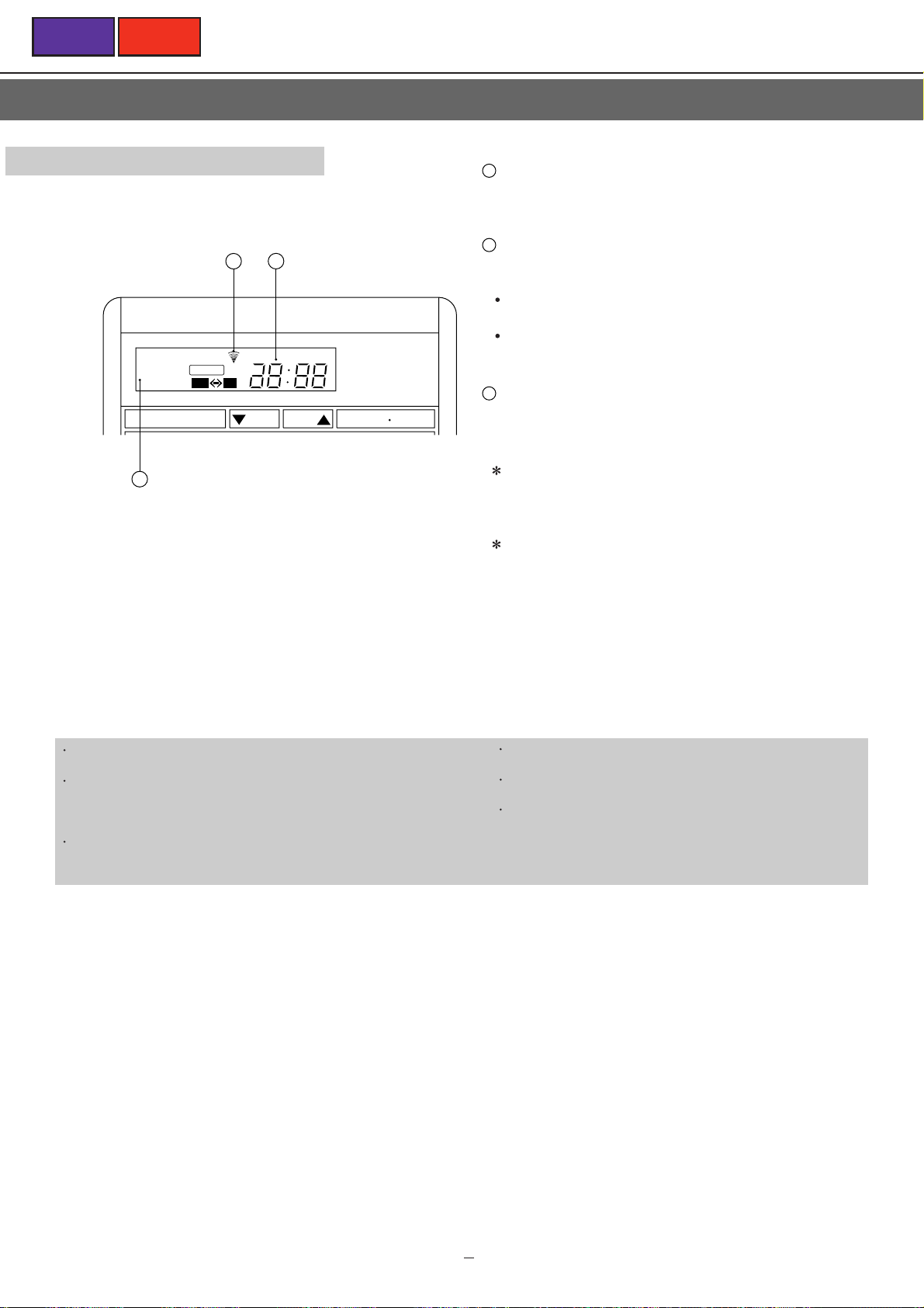
Remote Control Unit Display
Indicates the timer setting.
1
Transmit Indicator
This indicator is displayed when a signal is sent to the
air conditioner.
2
Time Display
Indicates either the current time or the timer setting (24hour display,from 0:00 to 23:59).
When the word "CLOCK" is shown, the display
indicates the current time.
When the word " TIMER " is shown, the display
indicates the timer setting.
2
Time Mode Display
Indicates the timer mode (OFF timer, ON timer,
PROGRAM timer, SLEEP timer, NON-STOP).
When the remote control unit's batteries run low, the
display (especially the transmit indicator) will become
faint. Use this as a guide to indicate when batteries
should be replaced.
To facilitate explanation, the accompanying illustration
has been drawn to show all possible indicators ; in actual
operation, however, the display will only show those
indicators appropriate to the current operation.
Signals will not be transmitted properly if a wall, curtain, or other
object is between the air conditioner and the remote control unit.
The air conditioner may fail to operate properly if strong direct
light is allowed to strike the signal receiver. Use a curtain to
shade strong sunlight from windows, and place strong lamps at
a distance away from the signal receiver.
If another electric appliance is operated by the remote control
unit move the appliance away or consult with authorized service
personnel.
Do not place the remote control unit in locations where it may be
subjected to heat from direct sunlight or from heating apparatus.
Do not subject the remote control unit to strong impacts, and do
not allow water or other liquids to splash on it.
When the remote control unit is used in rooms furnished with
instant-lighting type fluorescent lamps, the air conditioner may
fail to receive control signals correctly.Consult with authorized
service personnel when purchasing a new fluorescent lamp.
1 5
Page 11

BACK
NEXT
PREPARATION
Prepare the Remote Control Unit
Load batteries in the remote control unit and set the clock to the current time.
Set the Current TimeLoad Batteries (R6P / LR6 x 4)
Pull the battery cover in the direction of the
1
arrow to open it.
Press the TIME ADJUST button.
1
(Use the tip of a pen, etc., to press the button.)
CLOCK
Insert batteries, taking care to align the and
2
-
polarities correctly.
Push the battery cover in the direction of the
3
arrow to close it.
CAUTION!
Take precautions to prevent infants from accidentally swallowing
batteries.
When not using the remote control unit for an extended period,
remove the batteries to avoid possible leakage and damage to
the unit.
If leaking battery fluid comes in contact with your skin, eyes, or
mouth, immediately wash with copious amounts of water, and
consult your physician.
Dead batteries should be removed quickly and disposed of
properly, either by placing in a public battery collection
receptacle, or by returning to a properly equipped dealer.
Do not attempt to recharge dry batteries.
NOTE:
Never mix new and used batteries, or batteries of different
types.
Batteries should last about one year under normal use. If the
remote control unit's operating range becomes appreciably
reduced, replace the batteries and press the ACL button with
the tip of a ballpoint pen or other small object.
+
TIMER SET
AUTO AUTO
COOL
DRY
VASTER
CONTROL
FAN
FAN
CONTROL
TIME
START STOP
TIME ADJUST
LOW MED
HIGH
TEST RUN
ACL
TIME ADJUST
button
<Remote Control Unit Display>
The current time display will flash.
CLOCK
Press the SET TIME buttons to set the display
2
to the current time.
button: Press to advance the time setting.
button: Press to reverse the time setting.
(The time setting will be changed by 1 minute each time
a button is pressed; the time setting will change
continuously in 10-minute increments when a button is
held depressed.)
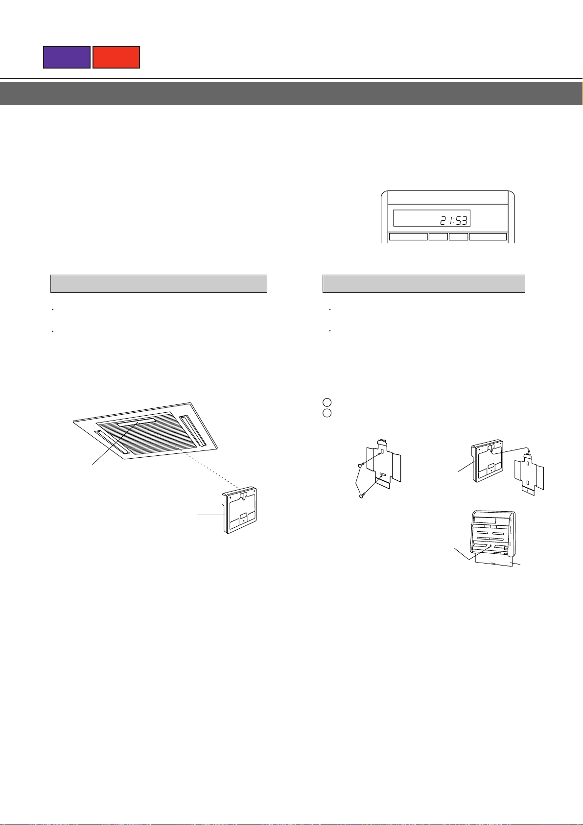
<Remote Control Unit Display>
The current time display will flash.
CLOCK
TIMER SET
(Example: When the display is set to 21:53)
TIME
START STOP
Page 12
BACK
NEXT
Press the TIME ADJUST button once again.
3
<Remote Control Unit Display>
The current time display will stop flashing.
CLOCK
To Use the Remote Control Unit
Install the remote control so that the front is facing the
photocell.
Install the remote control with a distance of 7 m
between the remote control and the grille photocell as
the criteria.
However, when installing the remote control, check that
it operates positively.
Photocell
Remote control unit
Remote Control Unit Holder
This holder allows the remote control unit to be
mounted on a post or wall.
If the holder is installed in a place that allows the
signals from the remote control unit to be properly
received by the main unit, the air conditioner can be
controlled without removing the remote control unit
from its holder.
1
Installing the holder.
2
Setting the remote control unit.
Remote
Screw
(
medium
)
control
unit
Machine screw
(
)
small
Hook
Battery
cover
Page 13
THRTMOSTAT
MASTER
CONTROL
FAN
CONTROL
AUTO AUTO
COOL
18
19 21 23 25 27
DRY
FAN
LOW MED
HIGH
TIME ADJUST
TEST RUN
ACL
LOUVER
TIMER SET
TIME
START STOP
NON STOP CLOCK
20 22
24
26 28
30
1
2
THRTMOSTAT
MASTER
CONTROL
FAN
CONTROL
AUTO AUTO
COOL
18
19 21 23 25 27
DRY
FAN
LOW MED
HIGH
TIME ADJUST
TEST RUN
ACL
LOUVER
TIMER SET
TIME
START STOP
NON STOP CLOCK
20
22 24
26 28
30
THRTMOSTAT
MASTER
CONTROL
FAN
CONTROL
AUTO AUTO
COOL
18
19 21 23 25 27
DRY
FAN
LOW MED
HIGH
TIME ADJUST
TEST RUN
ACL
LOUVER
TIMER SET
TIME
START STOP
NON STOP CLOCK
20
22 24
26
28 30
BACK
NEXT
AUTOMATIC OPERATION
During AUTO operation, the operating mode (cooling, etc.) will be selected automatically in accordance with room temperature
conditions at the time operation is started.
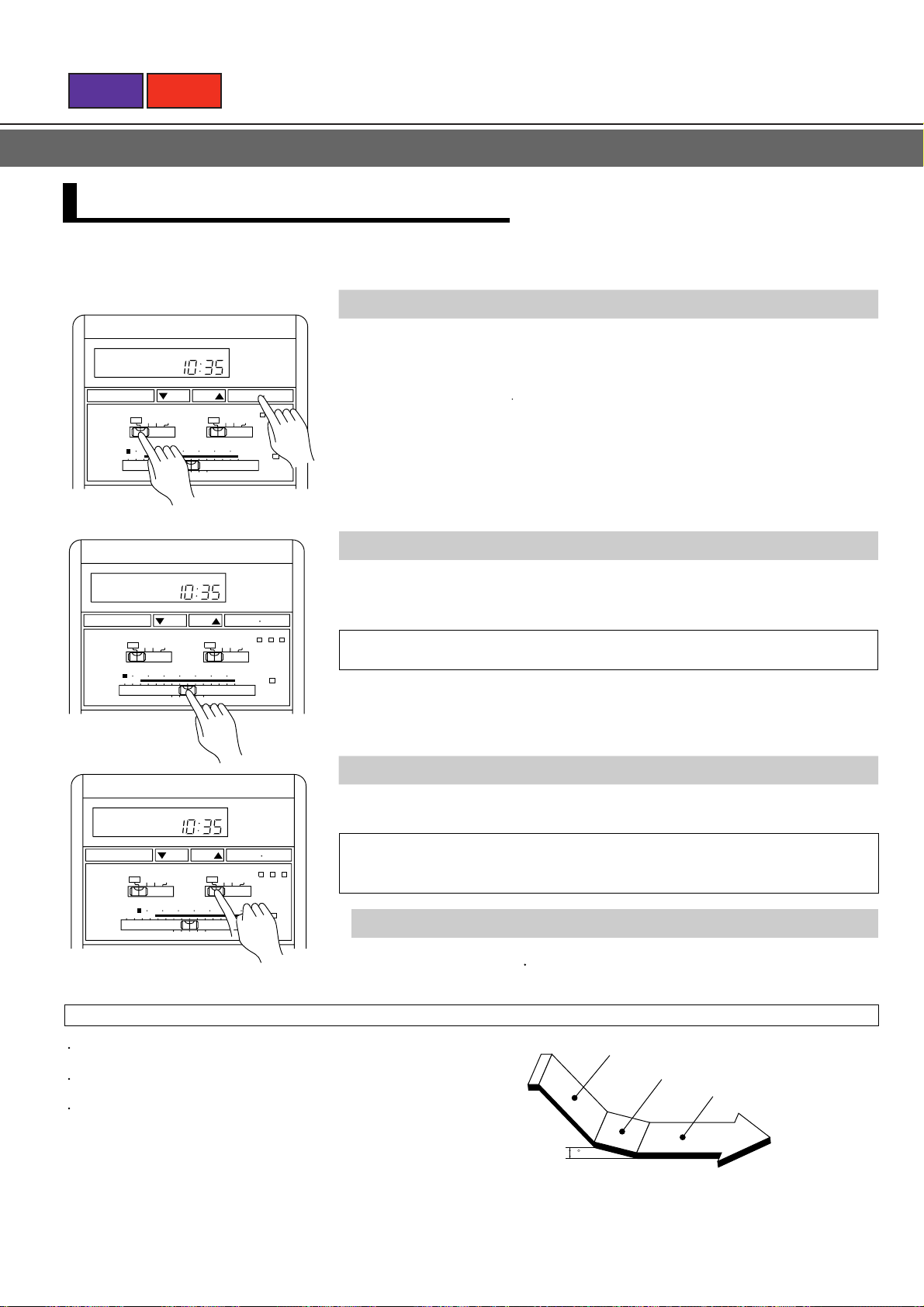
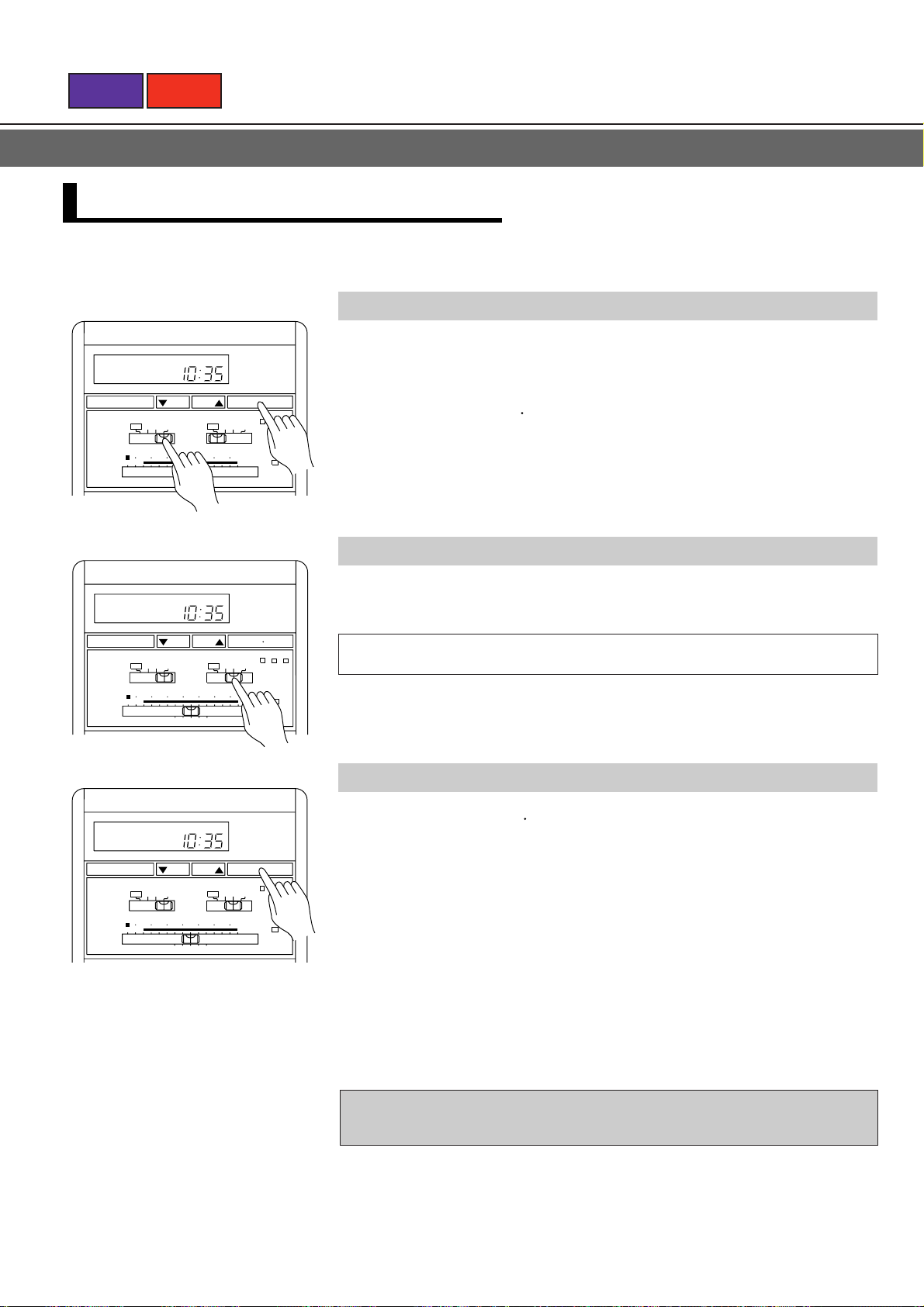
To Select Mode Operation
Set the MASTER CONTROL switch to the AUTO position.
1
Press the START STOP button.
2
Operation will start (operation will not start if the ON timer has been set).
<Indoor Unit Display>
The OPERATION indicator lamp will light.
To Set the Thermostat
Set the THERMOSTAT control to the desired position.
Range of temperature settings:
19, 21, 23, 25, 27˚C
To Set the Fan Speed
Set the FAN CONTROL switch to the desired position.
When the FAN CONTROL switch is set to the AUTO position,
the optimum fan speed will be selected automatically in accordance with room
temperature and other conditions.
To Stop Operation
Press the START STOP button.
About Automatic Operation
When the room temperature is 2°C higher than the set
temperature, the mode will switch between cooling and dry.
Most effective cooling will be produced by setting the FAN
CONTROL to HIGH.
During dry mode operation, FAN setting is switched to LOW for
gentle cooling effect, and the room fan may stop rotating
temporarily.
Cooling Operation
Dry Operation
2
C
Setting temperature
Thermostat control
Page 14
BACK
NEXT
MODE OPERATION (COOL, DRY)
Use the dry mode when you wish to eliminate room humidity without lowering the room temperature excessively.
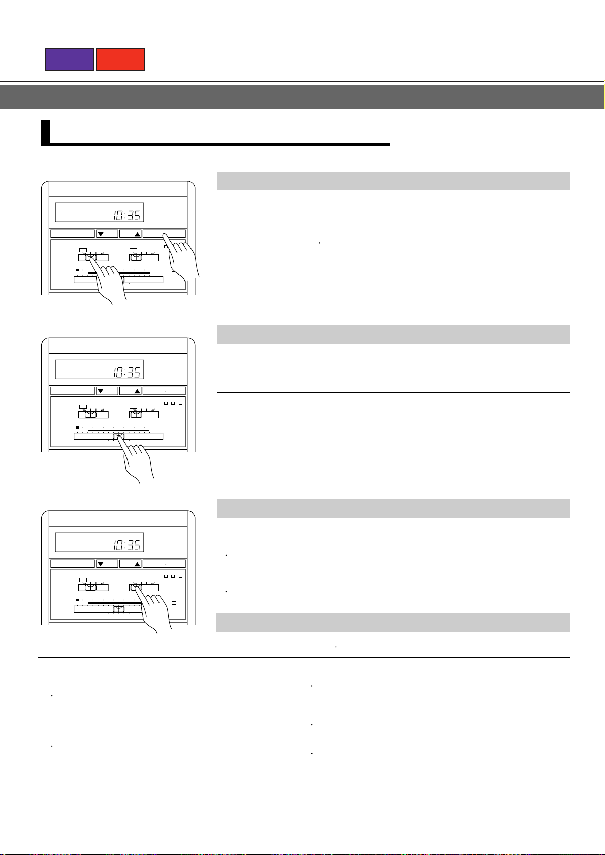
To Select Mode Operation
NON STOP CLOCK
Set the MASTER CONTROL switch to the desired position (COOL,
1
TIMER SET
AUTO AUTO
MASTER
CONTROL
THRTMOSTAT
18
START STOP
TIME
TIME ADJUST
TEST RUN
COOL
DRY
FAN
20 22
19 21 23 25 27
1
FAN
CONTROL
24
26 28
LOW MED
30
ACL
HIGH
LOUVER
2
DRY).
Press the START STOP button.
The unit will start operating in the selected mode (operation will not start if the ON
timer has been set).
<Indoor Unit Display>
The OPERATION indicator lamp will light.
To Set the Thermostat
NON STOP CLOCK
TIMER SET
AUTO AUTO
MASTER
CONTROL
THRTMOSTAT
18
NON STOP CLOCK
TIMER SET
AUTO AUTO
MASTER
CONTROL
THRTMOSTAT
18
Set the THERMOSTAT control to the desired position.
2
START STOP
TIME
TIME ADJUST
TEST RUN
COOL
DRY
FAN
20
22 24
19 21 23 25 27
FAN
CONTROL
26 28
LOW MED
30
ACL
HIGH
LOUVER
Range of temperature settings: 18 to 30˚C
To Set the Fan Speed
Set the FAN CONTROL switch to the desired position.
START STOP
TIME
TIME ADJUST
TEST RUN
COOL
DRY
FAN
20
22 24
19 21 23 25 27
FAN
CONTROL
LOW MED
26
28 30
ACL
HIGH
LOUVER
When the FAN CONTROL switch is set to the AUTO position, the optimum fan
speed will be selected automatically in accordance with room temperature and
other conditions.
During the dry mode, fan speed is set automatically and cannot be changed.
To Stop Operation
Press the START STOP button.
About Mode Operation
Cooling
When using the cooling mode, set the temperature to a value
lower than the actual current room temperature. If it is set higher
than the current room temperature, the unit will not enter the
cooling mode and only the fan will operate.
Drying
In the dry mode, since preference will be given to removing
humidity, the room temperature may not be lowered to the
selected value.
When using the dry mode, set the temperature to a value lower
than the actual current room temperature. If it is set higher than
the current room temperature, the unit will not enter the dry
mode.
In the dry mode, the optimum fan speed will be set automatically
and cannot be changed. The fan will emit a very weak stream of
air.
In the dry mode, the room fan may occasionally stop in order to
prevent room humidity from rising.
Page 15
BACK
NEXT
MODE OPERATION (FAN)
Use this mode when you wish to recirculate the air in your room.
To Select Mode Operation
Set the MASTER CONTROL switch to the FAN position.
NON STOP CLOCK
1
TIMER SET
AUTO AUTO
COOL
MASTER
CONTROL
THRTMOSTAT
18
NON STOP CLOCK
TIMER SET
AUTO AUTO
MASTER
CONTROL
THRTMOSTAT
18
NON STOP CLOCK
START STOP
TIME
TIME ADJUST
TEST RUN
DRY
20
FAN
CONTROL
22 24
19 21 23 25 27
FAN
1
LOW MED
26
28 30
ACL
HIGH
LOUVER
2
Press the START STOP button.
2
Operation will start (operation will not start if the ON timer has been set).
<Indoor Unit Display>
The OPERATION indicator lamp will light.
To Set the Fan Speed
Set the FAN CONTROL switch to the desired position.
START STOP
TIME
TIME ADJUST
TEST RUN
COOL
DRY
FAN
20
22
19 21 23 25 27
FAN
CONTROL
24 26
LOW MED
28 30
ACL
HIGH
LOUVER
When the AUTO fan speed is selected in the FAN mode, the fan speed will
automatically be set on MED.
To Stop Operation
Press the START STOP button.
TIMER SET
AUTO AUTO
COOL
MASTER
CONTROL
THRTMOSTAT
18
DRY
20
FAN
CONTROL
22
19 21 23 25 27
FAN
24 26
TIME
START STOP
TIME ADJUST
LOW MED
HIGH
28 30
TEST RUN
LOUVER
ACL
NOTE:
Do not allow the air conditioner's air stream to directly strike a kerosene or other space heater.
Incomplete combustion or fires may result.
Page 16
BACK
NEXT
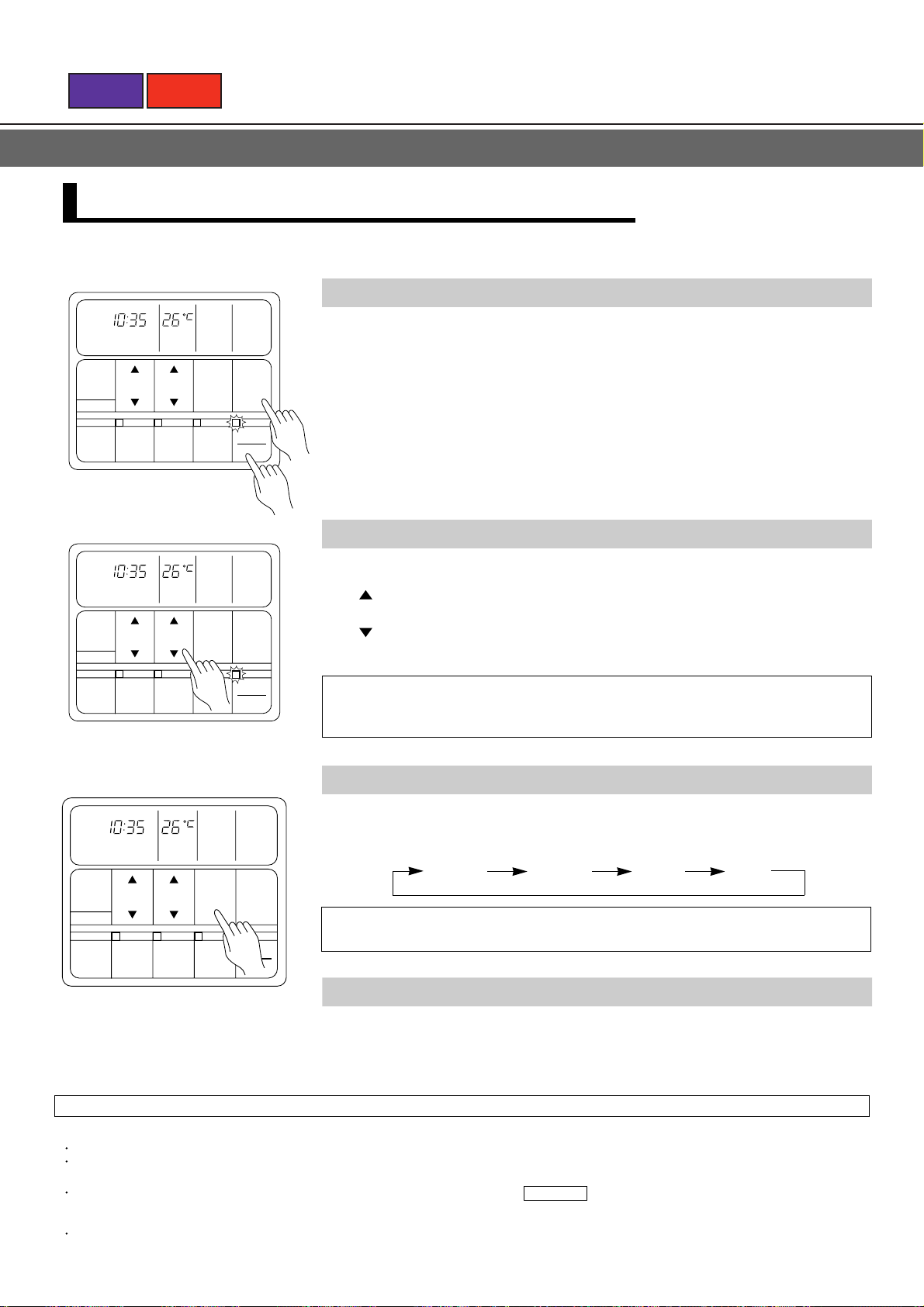
TIMER OPERATION
Press the START•STOP button; after the unit starts operation perform the following procedure:
OFF Timer/ON Timer
TIMER
OFF
TIMER SET
TIME
START STOP
Example: To set for OFF timer
TIMER
ON
TIMER SET
TIME
START STOP
1
Press the TIMER button, so that the timer mode display shows only
OFF or ON.
The timer will start operating (if the ON timer has been set, the unit will stop
operating).
<Indoor Unit Display>
The TIMER indicator lamp will light.
Each time the button is pressed the timer function changes in the following order:
RESET SLEEP OFF ON
PROGRAM (OFF ON, OFF ON)
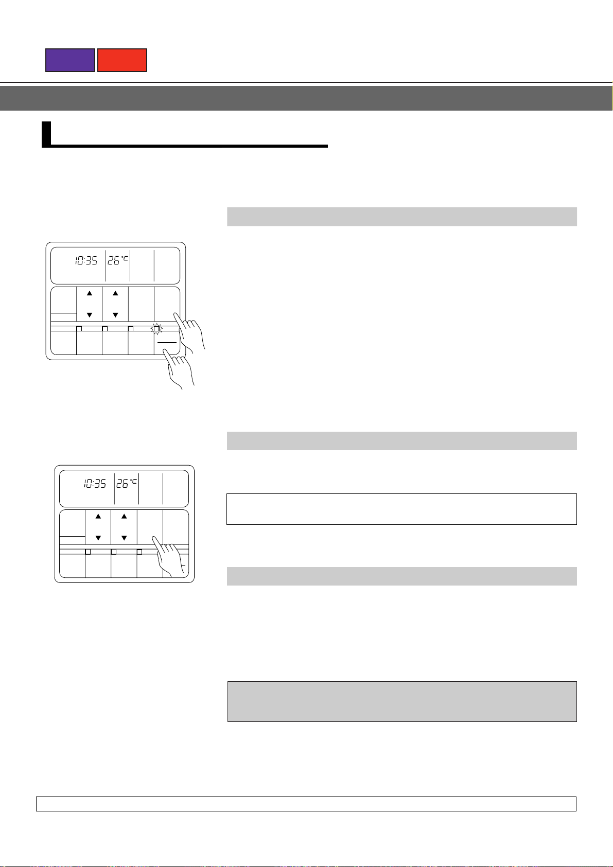
Example: To set for ON timer
TIMER
OFF
TIMER SET
TIME
START
STOP
Example: To set the ON timer to turn
the air conditioner off at
00:00
To Confirm or Change Settings Before
Starting Operation
To confirm settings
Press the TIMER button once. (The timer
setting information will be displayed for 15
seconds after the TIMER button is
pressed.)
To change settings
Confirm the settings as noted above, then
press the SET TIME button and TIMER
button as necessary to change the
desired timer setting. (The timer settings
will be displayed for 15 seconds after the
button is pressed.)
After confirming or changing the settings,
press the START•STOP button to start
operation.
Press the SET TIME buttons to adjust the time (the accompanying
2
illustration shows the OFF timer).
Button: Press to advance the time setting.
Button: Press the reverse the time setting.
(Each time a button is pressed the time will change in 5-minute increments; when
held depressed the time will change continuously in 10-minute increments.)
To Change the Timer Setting During
Operation
Operate as noted in step 2.
To Change the Timer Mode During
Operation
Press the TIMER button and set the unit to
the desired mode.
To Cancel the Timer Mode During
Timer Operation
Press the TIMER button and set the display
to "NON STOP" (the unit will switch to nonstop operation).
To Stop Operation During Use of
Timer Mode
Press the START•STOP button.
During operation of the ON timer, the
indoor unit's OPERATION indicator lamp
will not light (the TIMER indicator lamp
will light instead).
When the time reaches the set value, the
unit will start operation and the
OPERATION indicator lamp will light.
Page 17
BACK
NEXT
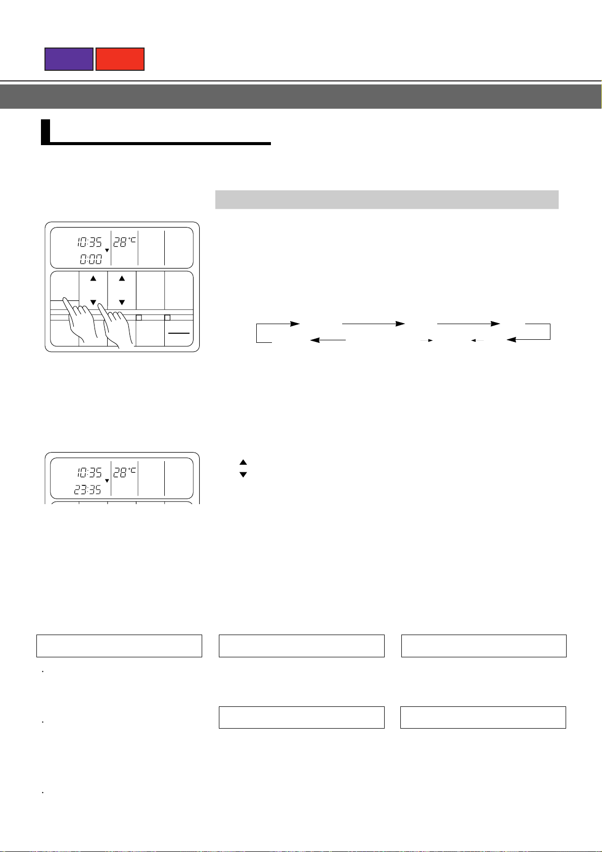
PROGRAM TIMER
Press the START•STOP button; after the unit starts operation perform the following procedure:
To Use the PROGRAM Timer
Press the TIMER button to select the "OFF" and "ON" timer modes
1
TIMER
OFF
TIMER SET
TIME
START STOP
To select OFF timer mode
and make the respective timer settings.
Press the TIMER button so that the display shows OFF ON
2
or OFF ON as desired.
TIMER
ON
TIMER SET
TIME
START STOP
To select ON timer mode
To Confirm or Change Settings Before
Starting Operation
See TIMER OPERATION
To Change Settings After Starting
Operation
<Remote Control Unit Display>
For 15 seconds, the display will switch between the "OFF timer" time and the "ON
timer" time. Then, it will switch to display the time setting for the timer operation
which will function first (the one closest to the current actual time).
<Indoor Unit Display>
The TIMER indicator lamp will light.
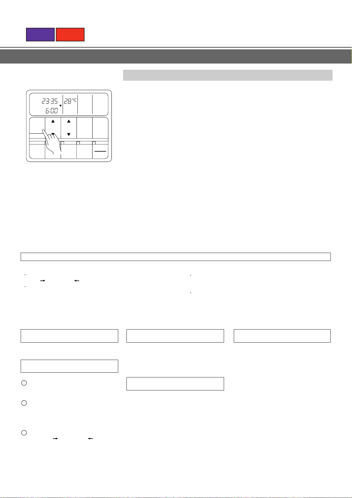
(Example: To set the OFF timer for 23:35 and the ON timer for 6:00)
Displayed
alternately
PROGRAM
TIMER
OFF
PROGRAM
TIMER
ON
After 15 seconds
TIMER
PROGRAM
OFF ON
To Change the Timer Mode During
Operation
Press the TIMER button and set the unit to
the desired mode.
To Stop Operation During Use of
Timer Mode
See TIMER OPERATION
1 Follow the instructions in step 1 of p.15 to
display the timer mode whose time
setting you wish to change.
2.Follow the instructions in step 2 to p.15 to
change the timer setting.
To change both the OFF timer and ON
timer settings, perform both of the above
steps 1,2 for each setting.
3.Press the TIMER button to display either
"OFF ON" or "OFF ON".
To Cancel the Timer Mode During
Timer Operation
Press the TIMER button and set the display
to "NON STOP" (the unit will switch to non
stop operation).
Page 18

BACK
NEXT
SLEEP TIMER OPERATION
The SLEEP timer is different from other timer functions, in that it is used to set the amount of time the air conditioner operates
until it turns off (in the example shown, the air conditioner will turn off two hours after the current time).
Press the START•STOP button; after the unit starts operation perform the following procedure:
To Use the SELECT Timer
Press the TIMER button, so that the timer mode display shows only
1
SLEEP.
SLEEP
TIMER
OFF
TIMER SET
TIME
START STOP
<Indoor Unit Display>
The TIMER indicator lamp will light.
SLEEP
TIMER
OFF
TIMER SET
Example: To set the SLEEP timer
to turn the air conditioner
off after two hours.
TIME
START STOP
Press the SET TIMER buttons to adjust the time (the accom-
2
panying illustration shows the SLEEP timer).
Button: Press to advance the time setting
Button: Press to reverse the time setting
(Each time a button is pressed the time will change in 5-minute increments; when
held depressed the time will change continuously in 10-minute increments.)
To Confirm or Change Settings Before Starting Operation
See TIME OPERATION
To Change the Timer Setting During Operation
Operate as noted in step 2.
To Change the Timer Mode During Operation
Prese the TIMER button and set the unit to the desired mode.
To Cancel the Timer Mode During Timer Operation
Press the TIMER button and set the display to "NON STOP" (the unit will switch to
non-stop operation).
To Stop Operation During Use of Timer Mode
See TIME OPERATION
About the SLEEP Timer
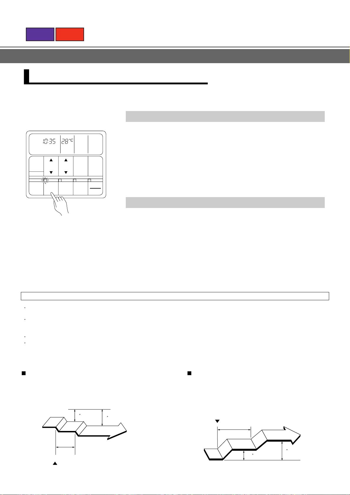
This function changes the room thermostat setting over time, to
prevent excessive room cooling while you sleep. After the set time
has elapsed, the air conditioner operation turns off automatically.
During cooling and dry operation
When the sleep timer is set, the thermostat setting is raised 1°C
each hour. After the thermostat setting has been raised a total
of 2°C, that setting is maintained for the remainder of the set
time, and operation is then stopped.
SLEEP Timer setting
1 hour
Set time
1
c
Stop
2
c
Page 19
BACK
NEXT
HOW TO CONTROL AIR DIRECTION
The power must be turned on in order to adjust the louver direction (attempting to move the
louvers by hand could result in damage).
CAUTION!
During cooling operation, if the louvers are adjusted to blow air directly downward for extended
periods of time, water may condense on the outlet port and louvers, and drip onto the floor.
Horizontal AUTO LOUVER
When the remote control unit's LOUVER button is pressed,
the automatic louver lamp lights and the direction of air flow
changes automatically between up and down.
Louver can be stopped at any position when the switch is
pressed to turn it off.
Horizontal louvers
CARE AND MAINTENANCE
Before cleaning the unit, be sure to stop the unit and disconnect the power supply.
CAUTION!
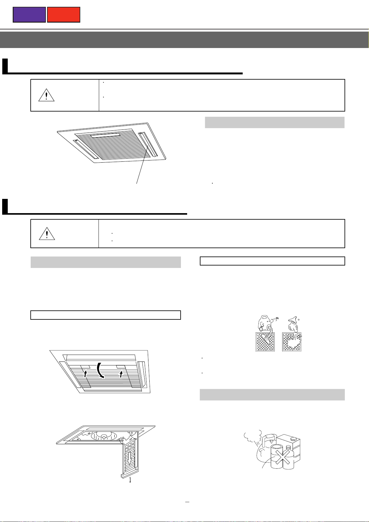
Cleaning the Air Filter
A clogged air filter reduces the airflow and weakens the
cooling effect. If the air filter remains clogged, it may cause
a defect.
How to remove the air filter
1. Push the intake grille pushbuttons two places until
you hear a "click".
Open the intake grille.
PUSH
Turn off the electrical breaker.
A fan operates at high speed inside the unit, and personal injury could result.
PUSH
How to clean the air filter
Clean the dust from the air filter by washing the filter with
water or blow it away with a vacuum cleaner. If the air filter
is very dirty, rinse the filter with warm or cool water mixed
with synthetic detergent and then wash the detergent
solution away with clean water and dry it.
Do not dry the air filter by exposing it to direct sunlight
or fire. This may damage the filter.
Avoid using hot water (40˚C or higher) to wash the
filter. This may damage the filter.
2. Pull the air filter once downward.
The air filter then comes out.
Cleaning the Indoor Unit
Wipe the cabinet with a dry soft cloth or clean with a cloth
dipped in hot water.
Use of a synthetic detergent is effective for cleaning.
Gasoline
Hot
Water
Polishing powder
Do not use gasoline, thinner, alcohol, benzine, chemicals,
polishing powder, etc. to clean the cabinet.
Benzine
Page 20
BACK
NEXT
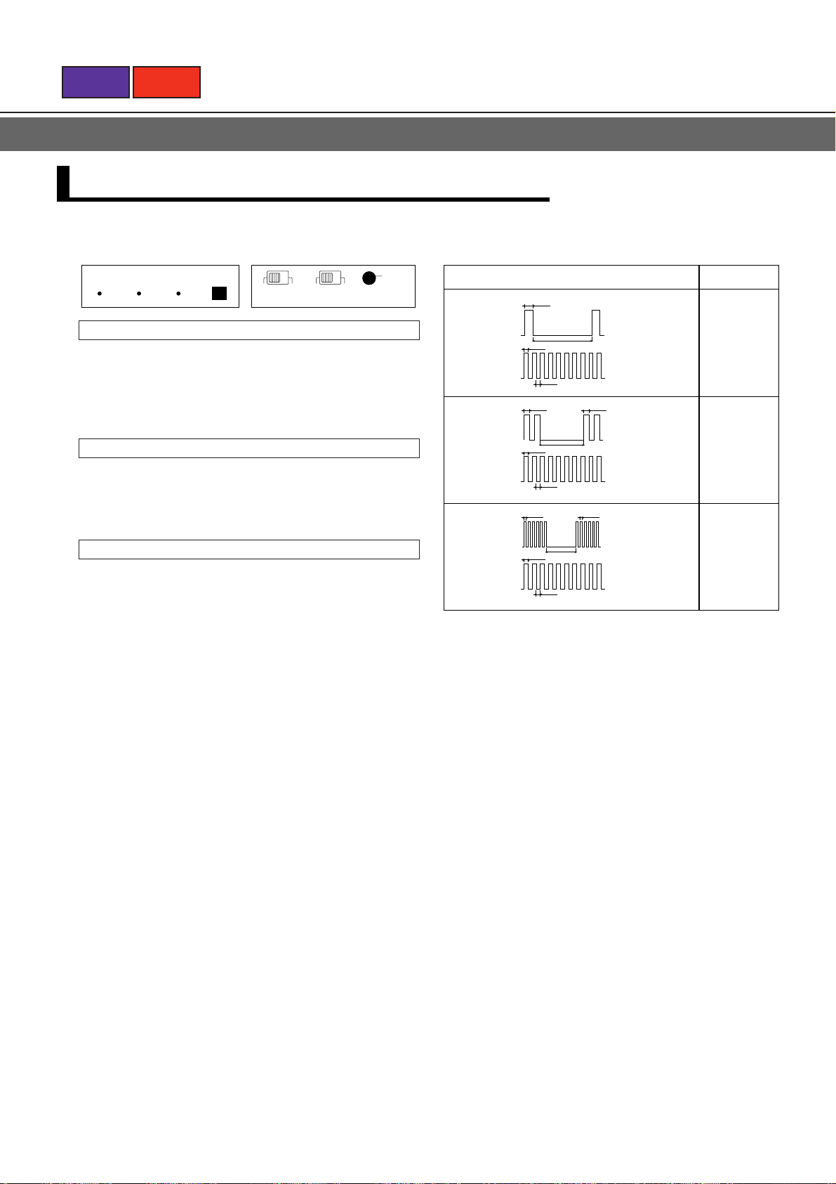
ERRORS AND SELF DIAGNOSIS
Operation can be checked by lighting and flashing of the grille display section OPERATION and TIMER lamps.
Perform judgment in accordance with the following:
MANUAL
OperationTimerLouver
OFF
POWER
ON
NORMAL
AUTO
RESTART
AUTO
Power ON
When the power is turned on, the grille display section
OPERATION and TIMER lamps flash quickly and
alternately.
When operation starts thereafter, flashing stops.
Test running
When the air conditioner is run by pressing the remote
control unit test running button, the OPERATION and
TIMER lamps flash slowly at the same time
Error
The OPERATION and TIMER lamps operate as follows
according to the error contents.
OPERATION
LAMP
TIMER
LAMP
OPERATION
LAMP
TIMER
LAMP
OPERATION
LAMP
TIMER
LAMP
Error display Error contents
0.5sec
ON
OFF
ON
OFF
ON
OFF
ON
OFF
ON
OFF
ON
OFF
0.1sec
0.1sec
0.5sec
0.1sec
5sec
0.1sec
0.5sec
5sec
0.1sec
0.5sec
5sec
0.1sec
0.5sec
Single quick
flash
repeated
0.1 sec ON/
OFF repeated
Two quick
flashes
repeated
0.1 sec ON/
OFF repeated
Six quick
flashes
repeated
0.1 sec ON/
OFF repeated
Room
temperature
thermistor
abnormal
temperature
detected
Piping
thermistor
abnormal
remperature
detected
Float switch
ON for 3
minutes or
longer
Page 21
BACK
NON STOP
OFF ON
TIMER
PROGRAM
REPEAT
FAN AUTO
FAN HIGH
FAN MED
FAN LOW
AUTO
HEAT
FAN
COOL
CLOCK
TIMER
TEMP
SET
TIME
ENERGY
SAVE
ZONE
CONTROL
LOUVER
START
STOP
TIMER
MODE
CLOCK ADJUST
FAN
CONTROL
MASTER
CONTROL
DEFROST TEST
OFF
ON
ON
OFF
SET
TEMP
1
2
3
4
5
6
7
89
10
11
12
13
14
Remote Controller
Display
NEXT
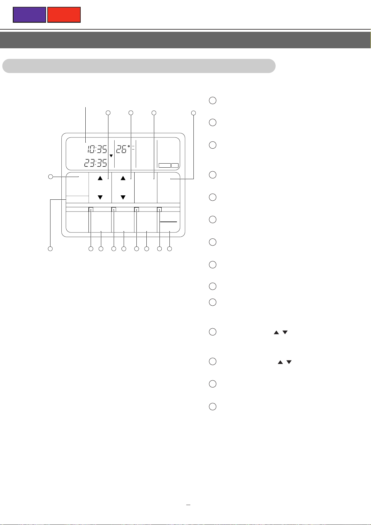
1.4.2 LIQUID CRYSTAL REMOTE CONTROLLER
START/STOP Button
1
Press to start and stop operation.
2
Operation Lamp
Lights up during operation and when the timer is on
3
LOUVER Button
Press it start and stop auto louver operation. Press it to
turn on and press again to turn off.
4
LOUVER Lamp
Lights up during auto louver operation.
For explanatory purposes, the figure showing
the remote controller display shows all
possible displays.
The actual display shows only that area that
is being adjusted or used.
5
ZONE CONTROL Button
Use to turn the zone control on and off.
6
ZONE CONTROL Lamp
Lights up when the unit is in the zone control mode.
ENERGY SAVE Button
7
Turns the energy efficient mode on and off.
8
ENERGY SAVE Lamp
Lights up when the unit is in the energy save mode.
9
CLOCK ADJUST Button
10
TIMER MODE Button
Use to change timer modes (NON STOP, OFF TIMER,
ON TIMER, PROGRAM TIMER, REPEAT TIMER).
11
SET TIME Button ( / )
Use to change the timer settings,
and to set the current time.
12
SET TEMP. Button ( / )
Use to change the temperature setting.
13
FAN CONTROL Button
Use to select the fan speed (AUTO, HIGH, MED, LOW).
1 16
14
MASTER CONTROL Button
Use to select the various operating modes (AUTO,
HEAT, FAN, COOL).
Page 22
BACK
NON STOP
OFF ON
TIMER
PROGRAM
REPEAT
FAN AUTO
FAN HIGH
FAN MED
FAN LOW
AUTO
HEAT
FAN
COOL
CLOCK
TIMER
TEMP
DEFROST TEST
OFF
ON
ON
OFF
4 5
6
7
321
NEXT
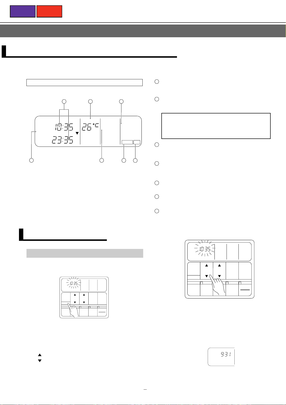
NAME AND FUNCTION OF PARTS
1
Remote Controller Display
* For explanatory purposes, the above figure shows all
possible displays. The actual display shows only that
area being adjusted or used.
Clock Display (CLOCK/TIMER)
Displays current or timer times (0:00 to 23:59).
2
Set Temperature Display (TEMP.)
Displays the set temperature.
Depending on the usage circumstances of the unit
(room width, outdoor temperature etc.)l, the displayed
temperature may differ from the actual room
temperature.
3
Operation Mode Display
Displays the operation mode (AUTO, HEAT, FAN,
COOL).
4
Timer Mode Display
Displays the timer mode (NON STOP, OFF TIMER, ON
TIMER, PROGRAM, REPEAT).
5
Fan Speed Display
Displays the current fan speed.
6
DEFROST Display
Displayed during defrosting.
7
TEST Display
Displayed during test operation.
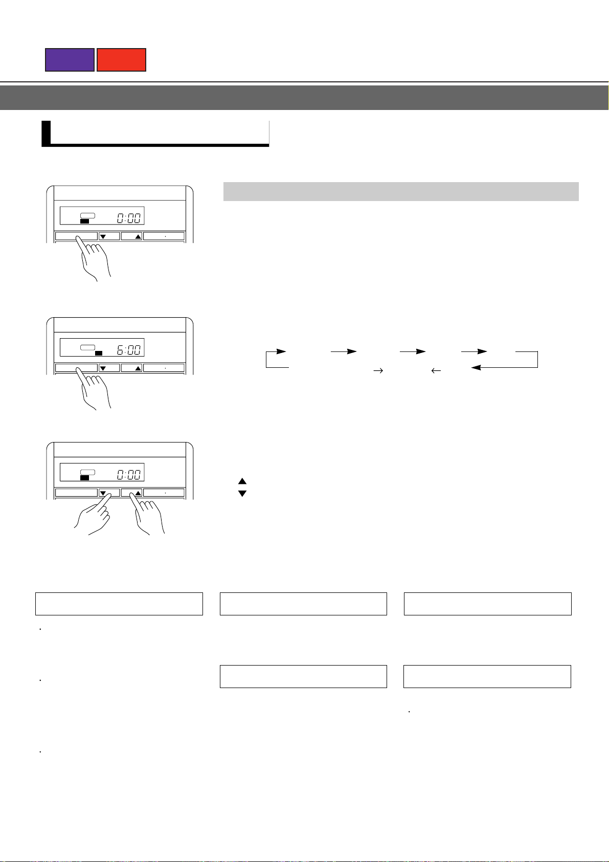
PREPARATION
Set the Current Time
Press the CLOCK ADJUST button for more
1
than three seconds.
CLOCK
TIMER
SET
MODE
TIME
CLOCK ADJUST
ENERGY
SAVE
<Remote Controller Display>
The current time display will flash.
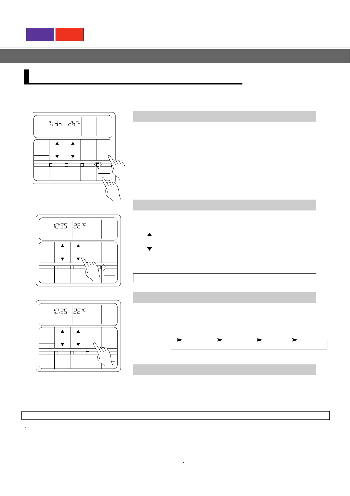
Press the SET TIME button and set the time.
SET
TEMP
ZONE
CONTROL
FAN
CONTROL
LOUVER
MASTER
CONTROL
START
STOP
2
: Use to advance the time forward.
: Use to turn the time back.
(Press once to move the time 1 minute; hold down and
the time will move 10 minutes at a time.)
CLOCK
TIMER
MODE
CLOCK ADJUST
SET
TIME
ENERGY
SAVE
CONTROL
SET
TEMP
ZONE
FAN
CONTROL
LOUVER
MASTER
CONTROL
START
STOP
<Remote Controller Display>
The current time display will flash.
Press the CLOCK ADJUST button again.
3
<Remote Controller Display>
The current time display will stop flashing.
CLOCK
Example: Set the time to 9:31.
1 17
Page 23
BACK
NEXT
AUTO CHANGEOVER OPERATION
NON STOP
TIMER
MODE
CLOCK ADJUST
NON STOP
TIMER
MODE
CLOCK ADJUST
SET
TIME
ENERGY
SAVE
SET
TIME
ENERGY
SAVE
SET
TEMP
ZONE
CONTROL
SET
TEMP
ZONE
CONTROL
FAN HIGH
FAN
CONTROL
LOUVER
FAN HIGH
FAN
CONTROL
LOUVER
AUTOCLOCK TEMP
MASTER
CONTROL
START
STOP
AUTOCLOCK TEMP
MASTER
CONTROL
START
STOP
1
To Select AUTO CHANGEOVER Operation
Press the START/STOP button.
1
The unit will start and the operation lamp will light up.
Press the MASTER CONTROL button to select AUTO.
2
The operating mode "AUTO" will appear alone in the display.
2
To Set the Thermostat
Set the SET TEMP. button to the desired temperature.
: Use to raise the set temperature.
(Press the button once to raise the temperature 1°C).
: Use to lower the set temperature.
(Press the button once to lower the temperature 1°C).
The temperature can be set 18 to 30°C .
To Change the Fan Speed
NON STOP
TIMER
MODE
CLOCK ADJUST
SET
TIME
ENERGY
SAVE
SET
TEMP
ZONE
CONTROL
FAN HIGH
FAN
CONTROL
LOUVER
AUTOCLOCK TEMP
MASTER
CONTROL
START
STOP
Press the FAN CONTROL button to select the fan speed.
Every time you press the FAN CONTROL button, the speed changes as shown.
To Stop Operation
Press the START/STOP button.
<Remote Controller Display>
The display contents disappear and only the current time is displayed.
About AUTO CHANGEOVER Operation
When AUTO CHANGEOVER operation is selected, the air
conditioner selects the appropriate operating mode (Cooling or
Heating) in response to your room's temperature.
When AUTO CHANGEOVER operation first selected, the fan
will operate at very low speed for about one minute, during
which time the unit detects the room conditions and selects the
proper operating mode.
When the air conditioner has adjusted your room's temperature
to near the thermostat setting, it will begin monitor operation. In
AUTO HIGH MED LOW
the monitor operation mode, the fan will operate at low speed. If
the room temperature subsequently changes, the air conditioner
will once again select the appropriate operation (Heating, Cooling)
to adjust the temperature to the value set in the thermostat.
(The monitor operation range is ±2°C relative to the thermostat
setting.)
If the mode automatically selected by the unit is not what you
wish, see MODE OPERATION and select one of the mode operation
(HEAT, COOL, FAN).
Page 24
BACK
NEXT
MODE OPERATION (HEAT, COOL)
Steps are recorded by the unit, after entering in this information, you need only press the START/STOP button to control the unit.
NON STOP
CLOCK TEMP
TIMER
MODE
CLOCK ADJUST
NON STOP
CLOCK TEMP
TIMER
MODE
CLOCK ADJUST
SET
TIME
ENERGY
SAVE
SET
TIME
ENERGY
SAVE
SET
TEMP
ZONE
CONTROL
SET
TEMP
ZONE
CONTROL
FAN HIGH
FAN
CONTROL
LOUVER
FAN HIGH
FAN
CONTROL
LOUVER
COOL
MASTER
CONTROL
START
STOP
COOL
MASTER
CONTROL
START
STOP
1
To Select Mode Operation
Press the START/STOP button.
1
The unit will start and the operation lamp will light up.
Press the MASTER CONTROL button.
2
Select either HEAT or COOL.
2
To Set the Thermostat
Set the SET TEMP. button to the desired temperature.
: Use to raise the set temperature.
(Press the button once to raise the temperature 1°C ).
: Use to lower the set temperature.
(Press the button once to lower the temperature 1°C ).
Range of temperature setting:
For heating mode....................................................................... 16 to 30°C
For cooling mode........................................................................ 18 to 30°C
To Set the Fan Speed
NON STOP
CLOCK TEMP
TIMER
MODE
CLOCK ADJUST
SET
TIME
SET
TEMP
FAN HIGH
FAN
CONTROL
COOL
MASTER
CONTROL
Press the FAN CONTROL button to select the fan speed.
Every time you press the FAN CONTROL button, the speed changes as shown.
AUTO HIGH MED LOW
When the AUTO fan speed is selected in the heating or cooling modes, the fan
speed will vary with room conditions.
ENERGY
SAVE
ZONE
CONTROL
LOUVER
START
STOP
To Stop Operation
Press the START/STOP button.
<Remote Controller Display>
The display contents disappear and only the current time is displayed.
About Mode Operation
Heating
Always set the temperature higher than the current room temperature. If it is set lower than the current room temperature, heating will not start.
For about 3 to 5 minutes after starting heating, the fan will operate very slowly, then switch to the selected fan setting.
This period allows the indoor unit's heat-exchanger to perform before emitting warm air.
During defrosting, the heating mode will be temporarily interrupted. DEFROST will be shown on the remote controll er display.
Cooling
Always set the temperature lower than the current room temperature. If it is set higher than the current room temperature, the unit will not enter
the cooling mode and only the fan will operate.
Page 25
BACK
NEXT
MODE OPERATION (FAN)
Steps are recorded by the unit, after entering in this information, you need only press the START/STOP button to control the unit
To Select MODE Operation
NON STOP
CLOCK TEMP
TIMER
MODE
CLOCK ADJUST
NON STOP
TIMER
MODE
CLOCK ADJUST
SET
SET
TIME
TEMP
ENERGY
ZONE
SAVE
CONTROL
CLOCK TEMP
SET
TIME
SET
TEMP
FAN HIGH
FAN
CONTROL
LOUVER
FAN HIGH
FAN
CONTROL
FAN
MASTER
CONTROL
START
STOP
FAN
MASTER
CONTROL
1
2
Press the START/STOP button.
1
The unit will start and the operation lamp will light up.
Press the MASTER CONTROL button to select FAN mode.
2
To Set the Fan Speed
Press the FAN CONTROL button to select the fan speed.
When the AUTO fan speed is selected in the FAN mode, the fan speed will
automatically be set on MED.
ENERGY
SAVE
ZONE
CONTROL
LOUVER
START
STOP
To Stop Operation
Press the START/STOP button.
<Remote Controller Display>
The display contents disappear and only the current time is displayed.
NOTE:
Do not allow the air conditioner's air stream to directly strike a kerosene or other space heater.
Incomplete combustion or fires may result.
About Mode Operation
The room temperature cannot be adjusted in the FAN mode. (The room temperature is not displayed on the remote controller.)
Page 26
BACK
NEXT
TIMER OPERATION
Press the START/STOP button; after the unit starts operation perform the following procedure:
OFF Timer/ON Timer
CLOCK
OFF
TIMER
TIMER
TIMER
MODE
CLOCK ADJUST
1
ENERGY
SAVE
CLOCK
OFF
TIMER
TIMER
TIMER
MODE
Example: Setting the OFF TIMER
CLOCK ADJUST
SET
TIME
SET
TIME
to
TEMP
OFF
ON
ON
OFF
SET
TEMP
ZONE
2
CONTROL
TEMP
OFF
ON
ON
OFF
SET
TEMP
23:35.
FAN HIGH
FAN
CONTROL
LOUVER
FAN HIGH
FAN
CONTROL
COOL
MASTER
CONTROL
START
STOP
COOL
MASTER
CONTROL
Press the TIMER MODE button and display
either OFF Timer or ON Timer.
1
The timer will start operating.
(If you set the ON timer, the air conditioner will stop operating).
Each time the button is pressed the timer function changes in the foollowing order:
RESET OFF ON
REPEAT PROGRAM (OFF
Press the SET TIME button and set the timer time.
2
: Use to advance the time forward.
: Use to turn the time back.
(Press once to move the time 1 minute; hold down and the
time will move 10minutes at a time.)
ON,OFF ON)
1
ENERGY
SAVE
ZONE
2
CONTROL
LOUVER
START
STOP
To Confirm or Change Settings Before
Starting Operation
To confirm settings
Press the TIMER MODE button once.
(The timer setting information will be
displayed for 15 seconds after the TIMER
MODE button is pressed.)
To change settings
Confirm the settings as noted above, then
press the SET TIME button and TIMER
MODE button as necessary to change the
desired timer setting. (The timer settings
will be displayed for 15 seconds after the
button is pressed.)
After confirming or changing the settings,
press the START/STOP button to start
operation.
To Change the Timer Settings During
Operation
Operate as noted in step 2.
To Change the Timer Mode During
Operation
Press the TIMER MODE button and set the
unit to the desired mode.
To Cancel the Timer Mode During
Timer Operation
Press the TIMER MODE button and set the
display to "NON STOP" (the unit will switch
to non-stop operation).
To Stop Operation During Use of
Timer Mode
Press the START/STOP button.
Page 27
BACK
NEXT
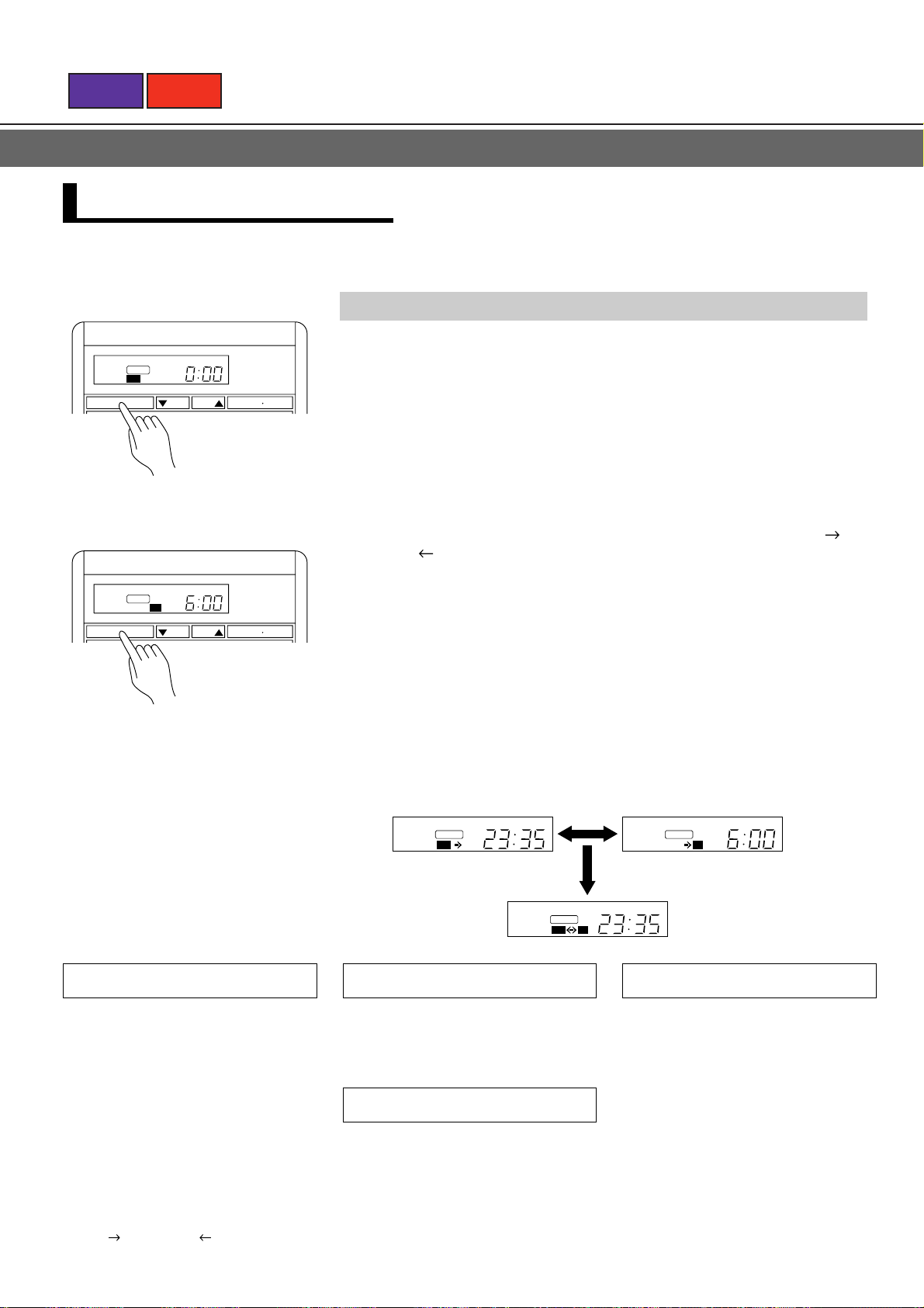
PROGRAM Timer/REPEAT Timer
CLOCK
TIMER
PROGRAM
TIMER
MODE
CLOCK ADJUST
ENERGY
SET
TIME
2
SAVE
TEMP
OFF
ON
SET
TEMP
ZONE
CONTROL
FAN HIGH
FAN
CONTROL
LOUVER
COOL
MASTER
CONTROL
START
STOP
Example:
If the OFF timer is set at 23:35 and the
ON timer at 6:00, and the unit is in the
PROGRAM timer mode.(Select the
REPEAT timer mode,
REPEAT" is
shown on the display.)
About Timer Operation
Setting the timer time.
1
Follow steps 1 and 2 See TIME OPERATION and set the times for the ON timer
and OFF timer modes.
Press the TIMER MODE button until the "PROGRAM" or "REPEAT"
2
mode display is shown.
PROGRAM Timer
Combines the OFF timer and the ON timer for one cycle.
(OFF
Starts operation from the OFF timer or the ON timer, whichever
is closer to the current time.
To Confirm or Change Settings Before
Starting Operation
See TIME OPERATION
To Change Settings After Starting
Operation
1
Follow the instructions in step 1 to display
the timer mode whose time setting
you wish to change.
2
Follow the instructions in step 2 to change
the timer setting.
To change both the OFF timer and ON
timer settings, perform both of the above
steps 1,2 for each setting.
Press the TIMER MODE button to display
3
either "OFF ON" or "OFF ON".
ON, or OFF ON)
To Change the Timer Mode During
Operation
Press the TIMER MODE button and set the
unit to the desired mode.
To Cancel the Timer Mode During
Timer Operation
Press the TIMER MODE button and set the
display to "NON STOP" (the unit will switch
to non stop operation).
REPEAT Timer
Combines the operation of the OFF timer and the ON timer (the
cycle described in the PROGRRAM timer above) so they repeat
the same cycle every day.
Starts operation from the OFF timer or the ON timer, whichever
is closer to the current time.
To Stop Operation During Use of
Timer Mode
Press the START/STOP button.
Page 28
BACK
NEXT
ENERGY SAVE OPERATION
To Use the ENERGY SAVE
NON STOP
CLOCK TEMP
TIMER
SET
MODE
CLOCK ADJUST
About the ENERGY SAVE
TIME
ENERGY
SAVE
SET
TEMP
ZONE
CONTROL
FAN HIGH
FAN
CONTROL
LOUVER
COOL
MASTER
CONTROL
START
STOP
Press the ENERGY SAVE button.
The unit will run in the ENERGY SAVE mode.
To Stop the ENERGY SAVE
Press the ENERGY SAVE button one more time.
The ENERGY SAVE mode will be turned off.
<Remote Controller Display>
The ENERGY SAVE light goes off, and the unit will return to the former operating
conditions.
The energy conservation mode (ENERGY SAVE) raises the set temperature slightly in the cooling mode and lowers the set temperature in the
heating mode, using a computer program to economically control the operation of the unit.
If you press the ENERGY SAVE button while the air conditioner is on, it will change to the conservation mode. If you press the ENERGY SAVE
button while the unit is in the timer mode (ON timer, PROGRAM timer, or REPEAT timer), the unit will go into the conservation mode when the
unit starts with the timer.
If you turn off the air conditioner while in the conservation mode, the mode will be shut off.
The temperature set on the remote controller will not change if the energy save mode is used.
When Heating
After the ENERGY SAVE button is pressed, the set temperature
will be lowered about 1°C every 30 minutes. When it has lowered
a total of 2°C, then it will hold that temperature.
1
c
30 min.
2
c
When Cooling
After the ENERGY SAVE button is pressed, the set temperature
will be raised about 0.5°C every 30 minutes. When it has gone up
a total of 1°C, then it will hold that temperature.
Set to the ENERGY SAVE mode.
30 min.
1
0.5
c
c
Set to the ENERGY SAVE mode.
Page 29
BACK
NEXT
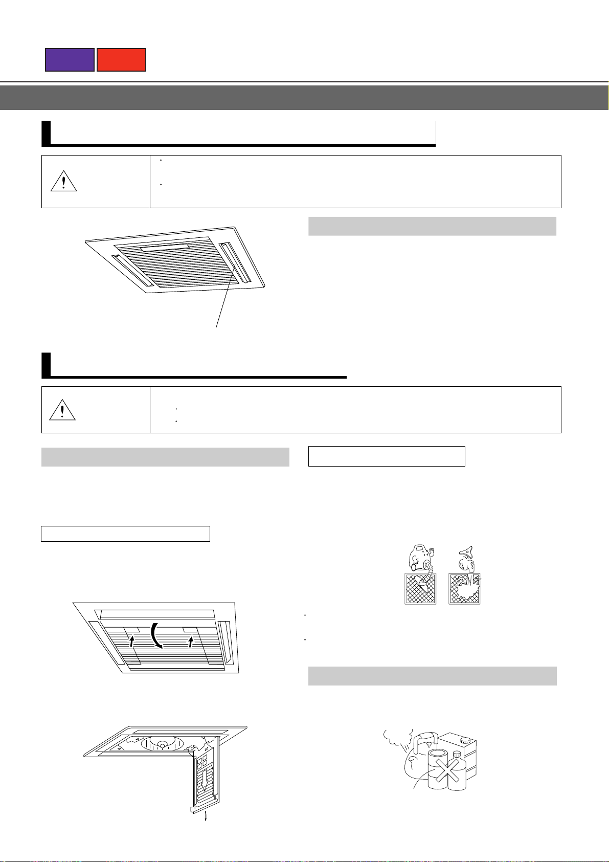
HOW TO CONTROL AIR DIRECTION
The power must be turned on in order to adjust the louver direction (attempting to move the
CAUTION!
louvers by hand could result in damage).
During cooling operation, if the louvers are adjusted to blow air directly downward for extended
periods of time, water may condense on the outlet port and louvers, and drip onto the floor.
Horizontal AUTO LOUVER
When the remote control unit's AUTO LOUVER button is
pressed, the automatic louver lamp lights and the direction
of air flow changes automatically between up and down.
Louver can be stopped at any position when the switch is
pressed to turn it off.
Horizontal louvers
During heating, point the louvers down so that warn air
reaches the floor.
CARE AND MAINTENANCE
Before cleaning the unit, be sure to stop the unit and disconnect the power supply.
CAUTION!
Cleaning the Air Filter
A clogged air filter reduces the airflow and weakens the
cooling effect. If the air filter remains clogged, it may cause
a defect.
How to remove the air filter
1. Push the intake grille pushbuttons two places until
you hear a "click".
Open the intake grille.
PUSH
Turn off the electrical breaker.
A fan operates at high speed inside the unit, and personal injury could result.
PUSH
How to clean the air filter
Clean the dust from the air filter by washing the filter with
water or blow it away with a vacuum cleaner. If the air filter
is very dirty, rinse the filter with warm or cool water mixed
with synthetic detergent and then wash the detergent
solution away with clean water and dry it.
Do not dry the air filter by exposing it to direct sunlight
or fire. This may damage the filter.
Avoid using hot water (40˚C or higher) to wash the
filter. This may damage the filter.
2. Pull the air filter once downward.
The air filter then comes out.
1 24
Cleaning the Indoor Unit
Wipe the cabinet with a dry soft cloth or clean with a cloth
dipped in hot water.
Use of a synthetic detergent is effective for cleaning.
Gasoline
Hot
Water
Polishing powder
Do not use gasoline, thinner, alcohol, benzine, chemicals,
polishing powder, etc. to clean the cabinet.
Benzine
Page 30
100 to 120
Hook shaft
Hook
BACK
NEXT
CARE AND MAINTENANCE
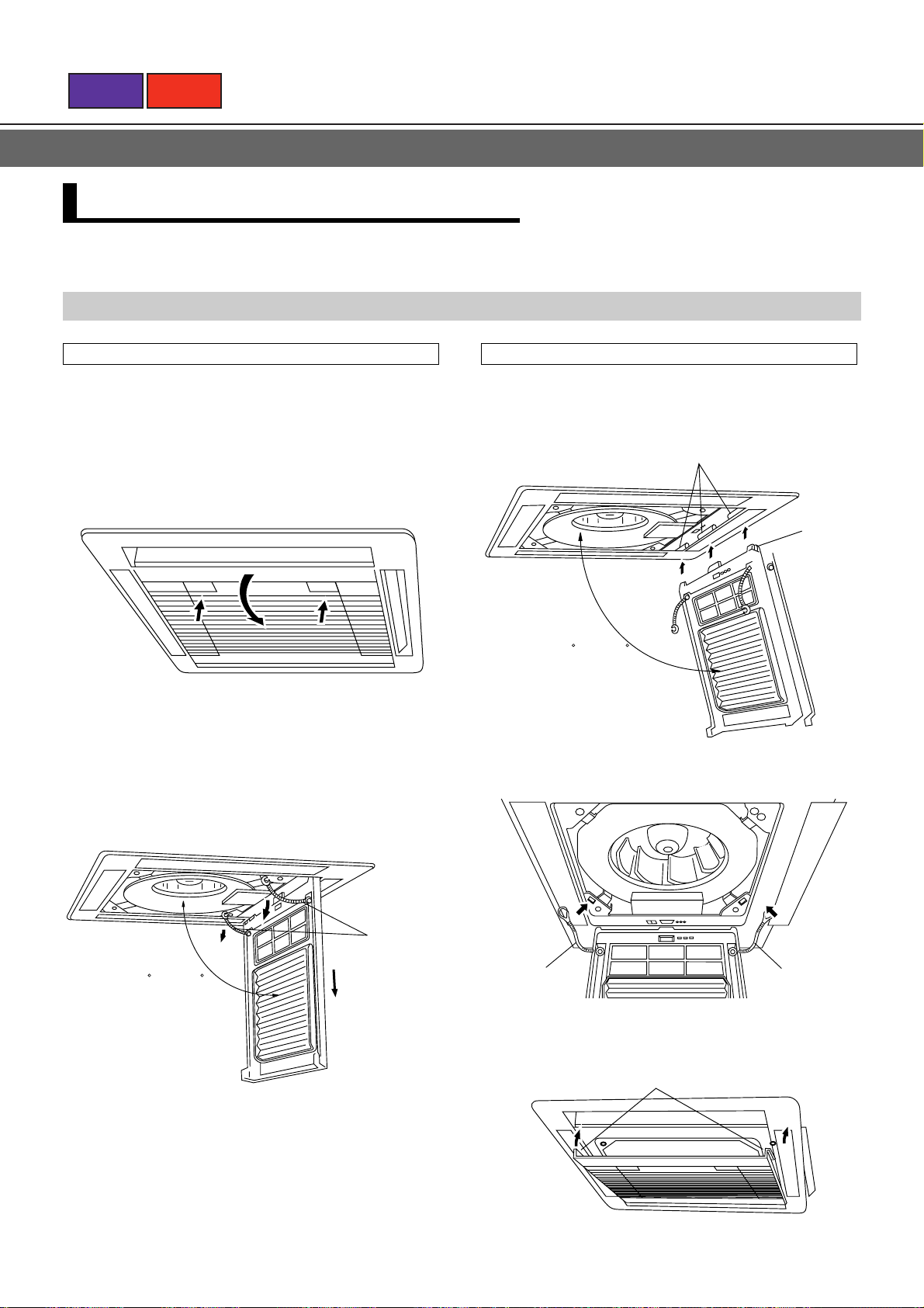
REMOVING / INSTALLING THE INTAKE GRILLE
Removing the intake grille
1. Push the intake grille pushbuttons (two places)
until you hear a "click".
Open the intake grille.
PUSH
PUSH
2. Remove the wire (hanger).
Removing the intake grille by opening it 100° to 120°.
Installing the intake grille
1. Tilt the intake grille 100
° to 120° and hook the
three hooks to the intake grille hook shaft.
2. Install the wire (hanger).
100 to 120
Wire
(
hanger
)
Wire
(
hanger
)
Wire
(
hanger
)
3. Push the intake grille pushbuttons (two places)
until you hear a "click".
Intake grille hooks
PUSH
PUSH
4. Hook the intake grille hooks to the grille
assembly.
Page 31

BACK
NEXT
ERRORS AND SELF DIAGNOSIS
CLOCK
OFF
ON
TIMER
MODE
CLOCK ADJUST
SET
TIME
ENERGY
SAVE
TEMP
ZONE
CONTROL
SET
FAN
CONTROL
LOUVER
MASTER
CONTROL
START
STOP
If there is a problem with the air conditioner, it will stop
running and "EE:EE"will be displayed instead of the clock.
1. If the operation lamp is on then press the
START/STOP button to turn it off.
2. Press the ENERGY SAVE and the ZONE
CONTROL buttons at the same time for more
than three seconds to start the self diagnosis
check.
An error code will be displayed in the clock
display area.
3. Press the ENERGY SAVE and the ZONE
CONTROL buttons again for more than three
seconds to end the self diagnosis check.
Error code Error
Communication error
(
indoor unit remote controller
Communication error
(
indoor unit outdoor unit
Room temperature sensor open.
Room temperature sensor shorted.
Indoor heat exchanger temperature
sensor open.
Indoor heat exchanger temperature
sensor shorted.
Outdoor heat exchanger temperature
sensor open.
Outdoor heat exchanger temperature
sensor shorted.
Float switch operated.
Outdoor temperature sensor open.
Outdoor temperature sensor shorted.
Discharge pipe temperature
sensor open.
Discharge pipe temperature
sensor shorted.
High pressure abnormal.
Discharge pipe temperature abno
rmal.
)
)
OPERATION DETAILS
Please read and understand the following details regarding this air conditioner.
Operation and Performance
Heating Performance
This air conditioner uses a heat pump which absorbs
heat from outside air and brings it indoors. As a result,
its heating performance is reduced as the temperature
of outside air drops. If you find that insufficient room
heat is produced, we recommend that you use the air
conditioner together with other heating appliances.
Heat-pump type air conditioners use warm-air
recirculation to warm your entire room. As a result,
some time will be required after starting operation until
your entire room becomes warm.
Microcomputer-controlled Automatic Defrosting
When the outside temperature is low and the humidity high,
frost will collect on the outside unit, reducing heater
efficiency. When this happens, the computer will
automatically start the defrost cycle. During the defrost
cycle, the indoor fan will shutdown and DEFROST will be
displayed on the remote controller. It will take anywhere
from 4 to 15 minutes before the air conditioner starts up
again.
When both indoor and outdoor temperatures are high during
use of the heating mode, the outdoor unit's fan may stop at
times.
When the outdoor temperature drops, the outdoor unit's fans
may switch to Low Speed, or one of the fans may stop
intermittently.
When Indoor and Outdoor Temperatures are High
Low Ambient Cooling
1 26
Page 32

BACK
NEXT
SYSTEM OPERATION
There are different ways the unit can be controlled.
<Spare Remote Controller>
Two remote controllers can be connected to one air
conditioner unit. The air conditioner operation contents
are the remote controller setting contents set later.
(Both remote controllers show the same display.)
To Use the ZONE CONTROL
NON STOP
CLOCK
TIMER
TIMER
MODE
CLOCK ADJUST
SET
TIME
ENERGY
SAVE
TEMP
OFF
ON
ON
OFF
SET
TEMP
ZONE
CONTROL
FAN HIGH
FAN
CONTROL
LOUVER
COOL
MASTER
CONTROL
START
STOP
When the ZONE CONTROL button is pressed while multiple air conditioners
are being centralized controlled, only the preset air conditioners stop.
Press the ZONE CONTROL button.
Preset units will stop.
To Stop the ZONE CONTROL
Press the ZONE CONTROL button one more time.
Those units that were stopped will start again.
<Control Several Units with just one Remote
Controller>
One remote controller can control up to 16 air conditioners.
All the air conditioners can be operated with the same
setting.
Unit No. 1 Unit No. 2 Unit No. 16
Auto Restart
When the air conditioner power was temporarily turned off by a power failure, etc., it will
restart automatically after the power recovers. (Operated by settings before the power failure.)
Page 33

BACK
NEXT
2. SPECIFICA TIONS
2.1 AU18, 18R, 25, 25R, 30, 30R, 1-PHASE 50Hz
MODEL
Capacity
Power supply 1 ~ 220-240V 50Hz
Total
input
Total
current
EER
Starting current A
Indoor
unit
Grille
Outdoor
unit
Refrigerant
circuit
Condition
Piping
Cooling
Heating
Cooling
Heating
Cooling
Heating
Cooling
Heating
Fan speedHiMed
Air
circulation
Noise level
(Sound
pressure)
Heat exchanger
Fan type x Q' ty
Fan motor output kW
Operation control
Dimensions
Weight kg Net/Gross
Dimensions
Weight kg Net/Gross
Fan speed
Air circulation Hi
Noise level dB
Heat exchanger
Fan type x Q 'ty
Fan motor output kW
Compressor type
Protection
Dimensions
Weight kg Net/Gross
Disch. pressure kg/cm
Suct. pressure kg/cm
Discharge temp. ˚C
Suction temp. ˚C
Refr. pipe length m
Disch. air temp.
Indoor
entering
air temp.
Ourdoor
entering
air temp.
Refrigerant charge kg(lb)
Pipe O D
size
Connection method
Between
kW
BTU/h
kW
BTU/h
kW
kW
A
A—
kW/kW
kW/kW —
r.p.m.
r.p.m.
r.p.m.
Low
Hi
Med
Low
Hi
Med
Low
H mm(inch)
W mm(inch)
D mm(inch)
H mm(inch)
W mm(inch)
D mm(inch)
Low
H mm(inch)
W mm(inch)
D mm(inch)
Cool
Heat
Cool
Heat
Liquid
Gas
Pipe length
Hi
Height
3
m
/h
3
m
/h
3
m
/h
dB
dB
dB
r.p.m.
r.p.m.
3
m
/h
kW 1.875 2 2.7Motor output
2
G
2
G
˚C
DB/WB ˚C
DB/WB ˚C
DB/WB ˚C
DB/WB ˚C
mm(inch)
mm(inch)
m
m
AU 18 AU 18R AU 25 AU 25R AU 30 AU 30R
5.25 - 5.40
17,900 - 18,400
—
—
2.05 - 2.15
—
10.0 - 10.5
2.56 - 2.51
66 / 74 68 / 76 67 / 75 68 / 76 94 / 108 96 / 110
Cooling Cooling Heating Cooling Cooling Heating Cooling Cooling Heating
19.8 19.1 19.7
5.0 5.2 4.5
99 90 85
9
13 13.5 41 14 13 42 11 12 45
1.14 (2.51) 1.65 (3.63) 1.95 (4.29) 2.07 (4.55) 1.80 (3.97) 2.20 (4.85)
5.10 - 5.15
17,400 - 17,500
5.20 - 5.25
17,700 - 17,900
1.95 - 2.05
1.95 - 2.05
9.6 - 10.2
9.6 - 10.1
2.62 - 2.51
2.67 - 2.56
50
500
430
360
1,000
850
700
41.5
37.0
34.0
0.037 0.050
216 (8 - 1/2") 302 (11-7/8")
26 / 33 38 / 45
740
280
2,590
56
Propeller x 1
0.060 x 1
Internal protector (OCR), High pressure relief valve
643 (25 - 5/16")
840 (33 - 1/16")
336 (13 - 1/4")
Max. 25 Max. 30 Max. 25
CASSETTE TYPE
7.00 - 7.10
23,900 - 24,200
—
—
2.64 - 2.77
—
12.8 - 13.2
—
2.65 - 2.56
—
Plate fin coil
Tubo fan x 1
Remote control
800 (31 - 1/2")
800 (31 - 1/2")
80 (3 - 5/32")
950 (37 - 13/32")
950 (37 - 13/32")
Plate fin coil
Hermetic (Recipro)
19.9
4.9
90
4
20.0 / (15.0)
15.88 (5/8")
6.95 - 7.05
23,700 - 24,100
7.60 - 7.85
25,900 - 26,800
2.60 - 2.73
2.45 - 2.55
12.7 - 13.0
11.4 - 11.8
2.67 - 2.58
3.10 - 3.08
61
580
510
430
1,200
1,025
850
45.0
42.0
39.0
6.5 / 11
20.1 21.2
4.9 4.0
101 81
9 1.0
5
27.0 / 19.0
35.0 / 24.0
7.0 / 6.0
9.53 (3/8")
Flare
Max.15
8.60 - 8.80
29,400 - 30,000
—
—
3.00 - 3.10
—
14.7 - 15.2
—
2.87 - 2.84
—
Propeller x 2
1,152 (45 - 11/32")
370 (14 - 9/16")
18.5
5.2
90
87 0.5
8.60 - 8.80
29,400 - 30,000
8.80 - 9.10
30,000 - 31,000
3.00 - 3.10
2.70 - 2.80
14.7 - 15.2
13.6 - 14.0
2.87 - 2.84
3.26 - 3.25
67
460
380
320
1,200
950
700
44.5
42.5
40.5
790
510
5,900
57
0.063 x 2
940 (37")
17.8 17.1
5.0 3.9
85 100
510
2 1
Page 34

BACK
NEXT
2.2 AU25, 36, 36R, 45, 45R 3-PHASE 50Hz
MODEL
Capacity
Power supply 3 ~ 380 - 415V 50Hz
Total
input
Total
current
EER
Starting current A
Indoor
unit
Grille
Outdoor
unit
Refrigerant
circuit
Condition
Piping
Cooling
Heating
Cooling
Heating
Cooling
Heating
Cooling
Heating
Fan speed
Air
circulation
Noise level
(Sound
pressure)
Heat exchanger
Fan type x Q' ty
Fan motor output kW
Operation control
Dimensions
Weight kg Net/Gross
Dimensions
Weight kg Net/Gross
Fan speed
Air circulation Hi
Noise level dB
Heat exchanger
Fan type x Q 'ty
Fan motor output kW
Compressor type
Protection
Dimensions
Weight kg Net/Gross
Disch. pressure kg/cm
Suct. pressure kg/cm
Discharge temp. ˚C
Suction temp. ˚C
Refr. pipe length m
Disch. air temp.
Indoor
entering
air temp.
Ourdoor
entering
air temp.
Refrigerant charge kg(lb)
Pipe O D
size
Connection method
Between
kW
BTU/h
kW
BTU/h
kW
kW
A
A—
kW/kW
kW/kW —
r.p.m.
Hi
r.p.m.
Med
Low
r.p.m.
Hi
Med
Low
Hi
Med
Low
H mm(inch)
W mm(inch)
D mm(inch)
H mm(inch)
W mm(inch)
D mm(inch)
Low
H mm(inch)
M mm(inch)
L mm(inch)
Cool
Heat
Cool
Heat
Liquid
Gas
Pipe length
3
m
/h
m3/h
3
/h
m
dB
dB
dB
Hi
r.p.m.
r.p.m.
3
m
/h
kW 1.870
2
G
2
G
˚C
DB/WB ˚C
DB/WB ˚C
DB/WB ˚C
DB/WB ˚C
mm(inch)
mm(inch)
Height
m
m
AU 25(3) AU 36(3) AU 36R(3) AU 45(3) AU 45R(3)
7.00 - 7.10
23,900 - 24,200
—
—
2.54 - 2.64
——
4.4 - 4.6
—
2.76 - 2.69
580
510
430
1,200
1,025
850
45.0
41.0
38.0
0.037 0.061 0.070
216 (8 - 1/2") 302 (11 - 7/8")
26 / 33 38 / 45
740 790
280
2,590
Propeller x 1
0.060 x 1
Internal protector (OCR) Internal protector (OCR), High pressure relief valve
643 (25 - 5/16")
840 (33 - 1/16")
336 (13 - 7/32")
67 / 57 94 / 108 95 / 110 102 / 116 108 / 122
Cooling Cooling Cooling Heating CoolingCooling Heating
19.6 18.8
4.8 5.1 5.0
84 90 95
15 6
14 11 12 42 12 12 46
2.03 (5.07) 2.15 (4.74) 2.8 (6.17) 3.15 (6.94) 3.4 (7.49)
15.88 (5/8") 19.05 (3/4")
Max. 35 Max. 50
3.73 - 3.80
2.76 - 2.76
35,200 - 36,000
—
—
6.4 - 6.4
—
—
57.5 58.056
CASSETTE TYPE
10.5 - 10.7
36,000 - 36,500
3.88 - 3.95
3.18 - 3.25
6.6 - 6.6
6.1 - 5.8 7.4 - 7.4
2.65 - 2.66
3.30 - 3.29
42 5532
570
470
380
1,400
1,150
900
49.0
45.0
42.5
Plate fin coil
Tubo fan x 1
Remote control
800 (31 - 1/2")
800 (31 - 1/2")
80 (31 - 5/32")
950 (37 - 13/32")
950 (37 - 13/32")
6.5 / 11
Plate fin coil
Hermetic (Recipro)
1.9
10
27.0 / 19.0
20.0 / (15.5)
35.0 / 24.0
7.0 / 6.0
9.53 (3/8")
Flare
Max. 30
510
Propeller x 2
0.063 x 2
1,152 (45 - 11/32")
940 (37")
370 (14 - 9/16")
16.820.2 19.0
4.4
80
18
5
12.4 - 12.710.3 - 10.5
42,500 - 43,500
—
—
—
—
—
—
5.0
90 90
46,000 - 47,000
4.45 - 4.57
7.5 - 7.5
2.79 - 2.78
680
570
490
1,700
1,500
1,200
53.5
50.0
46.5
790
5,5005,900
59.0
2.7Motor output
18.7
13.4 - 13.7
4.23 - 4.35
3.17 - 3.15
510
20.4
4.8 4.0
100
73
2 2
Page 35

BACK
NEXT
2.3 AU25, 25R, 36, 36R, 1-PHASE / AU45,45R 3-PHASE 60Hz
MODEL
Capacity
Power supply 1 ~ 220V 60Hz 3 ~ 220V 60Hz
Total
input
Total
current
EER
Starting current A
Indoor
unit
Grille
Outdoor
unit
Refrigerant
circuit
Condition
Piping
Cooling
Heating
Cooling
Heating
Cooling
Heating
Cooling
Heating
Fan speed
Air
circulation
Noise level
(Sound
pressure)
Heat exchanger
Fan type x Q' ty
Fan motor output kW
Operation control
Dimensions
Weight kg
Dimensions
Weight kg
Fan speed
Air circulation Hi
Noise level dB
Heat exchanger
Fan type x Q 'ty
Fan motor output kW
Compressor type
Protection
Dimensions
Weight
Disch. pressure
Suct. pressure kg/cm
Discharge temp. ˚C
Suction temp. ˚C
Refr. pipe length m
Disch. air temp.
Indoor
entering
air temp.
Ourdoor
entering
air temp.
Refrigerant charge kg(lb)
Pipe O D
size
Connection method
Between
W
W
W
W
A
A—
W/W
W/W —
Hi
r.p.m.
r.p.m.
Med
Low
r.p.m.
mm(inch)
mm(inch)
mm(inch)
Net/Gross
mm(inch)
mm(inch)
mm(inch)
Net/Gross
Hi
mm(inch)
mm(inch)
mm(inch)
Net/Gross
kg/cm
Gas
Height
3
m
/h
3
m
/h
3
m
/h
dB
dB
dB
r.p.m.
3
m
/h
kW 2 3.5 4.54Motor output
2
G
2
G
˚C
DB/WB ˚C
DB/WB ˚C
DB/WB ˚C
DB/WB ˚C
mm (inch)
mm (inch)
m
m
Hi
Med
Low
Hi
Med
Low
H
W
D
H
W
D
Low r.p.m.
H
M
L
kg
Cool
Heat
Cool
Heat
Liquid
Pipe length
AU 25 AU 25R AU 36 AU 36R AU 45 (3) AU 45R (3)
5,600
—
3,030
—
13.9
1.85
1,200
1,025
46.0
43.0
39.0
0.037 0.061
216 (8 - 1/2") 302 (11 - 7/8")
26 / 33 38 / 45
740
—
2,590
56 (COOL) 58 (HEAT) 58
Propeller x 1
0.060 x 1
643 (25 - 5/16")
840 (33 - 1/16")
336 (13 - 1/4")
67 / 75 68 / 76 94 / 108 96 / 110 102 / 115 108 / 122
Cooling Cooling Heating Cooling Cooling Heating Cooling Cooling Heating
24 25.3 21
5.2 5.3 4.0
96 108 74
7
15 15 45 12 14 46 12 14 46
1.75 (3.86) 2.07 (4.56) 2.2 (4.85) 2.6 (5.73) 3.35 (7.39) 3.60 (7.94)
15.88 (5/8") 19.05 (3/4")
Max. 15
Max. 25 Max. 50
7,500
3,250
2,700
15.2
12.7
1.73
2.78
66
580
510
430
850
280
Internal protector (OCR), High pressure relief valve
21.0 / (15.5) 21.0 / (15.5)
CASSETTE TYPE
9,000
—
4,600
—
21.5
—
1.96
—
77
560
510
460
1,400
1,250
1,100
48.5
46.0
43.5
Plate fin coil
Tubo fan x 1
Remote control
800 (31 - 1/2")
800 (31 - 1/2")
80 (3 - 5/32")
950 (37 - 3/32")
950 (37 - 13/32")
6.5 / 11
5,900 5,500
Plate fin coil
Hermetic (Recipro)
23
5.3
95
7
5
46.0 / 24.0
7.0 / 6.0
9.53 (3/8")
Flare
8,500
10,500 14,000
3,650
17.5
1.85
2.88
790
Propeller x 2
0.063 x 2
1,152 (45 - 11/32")
940 (37")
370 (14 - 9/16")
23 20
5.5 4.5
95 90
10 1
Max. 30
—
—
—
—
—
23.5
5.0
100
515 1
10,000
5,550
15.8
1.8
55
640
580
520
1,600
1,425
1,250
53.0
50.0
48.0
59.0
23.5 22.5
5.0 4.0
95 100
29.0 / 19.029.0 / 19.0
51
*The ceiling rear
4,750
14.0
2.95
510
2 3
Page 36

BACK
NEXT
3. OUTLINES AND DIMENSIONS
3.1 Grille
)
mm
33-15/32" (850mm)
)
mm
2-29/64" (62
3.2 AU18, 18R, 25, 25R
23/32" (18
)
mm
37-13/32" (950
18 (457mm)
37-13/32" (950mm)
)
mm
31-1/2" (800
)
mm
8-1/2" (216
)
mm
10 (256
31-1/2" (800mm)
3 1
)
mm
28-25/32" (731
Top hole size
mm mm
890
Drain Inside Dia. 32
Outside Dia. 37
3-1/32" (95mm)
(Large, Small pipe)
890
x
Ø
Ø
6-1/2" (165mm)
(Drain pipe)
Page 37

BACK
NEXT
3.3 AU30, 30R, 36, 36R, 45, 45R
18 (457mm)
)
mm
)
mm
31-1/2" (800
)
mm
)
mm
11-57/64"(302
13-15/32" (342
31-1/2" (800
mm
28-25/32" (731
Top hole size
890
mm
890
mm
)
Drain Inside Dia. 32
Outside Dia. 37
Ø
Ø
)
)
mm
mm
10" (253
(Drain pipe)
(Large, Small pipe)
4-7/32" (107
3 2
Page 38

BACK
NEXT
3.4 AO18, 18R, 25, 25R, 25(3)
33-1/16" (840mm)
)13-7/64" (333
mm
)
25-5/16" (643
1" (25
)
mm
31-21/32" (804
3.5 AO30, 30R, 36, 36R, 45, 45R
mm
13-1/4" (336
)
mm
)
)
mm
)
mm
45-11/32" (1152
29/32" (23
)
mm
15-3/4" (400
25-19/32"
)
(650
mm
37" (940
mm
14-9/16" (370mm)
16-23/32"
)
(425
mm
)
3 3
Page 39

BACK
NEXT
4. DATA
4.1 PERFORMANCE CURVE
4.1.1 AU18, AU25
120
110
Cooling
Low ambient operation model
100
90
Capacity(%)Total input(%)
80
70
100
90
80
0 5 10 15 20 30 35 40 45 505225
Indoor
DB/WB(˚C)
31/22
27/19
23/16
31/22
19/12.5
27/19
23/16
19/12.5
OUTDOOR DB (˚C)
4 1
Page 40

BACK
NEXT
4.1.2 AU25(3)
120
110
Cooling
Low ambient operation model
100
90
Capacity(%)Total input(%)
80
70
100
90
80
0 5 10 15 20 30 35 40 45 505225
4.1.3 AU18R, AU25R
Indoor
DB/WB(˚C)
31/22
27/19
23/16
31/22
19/12.5
27/19
23/16
19/12.5
OUTDOOR DB (˚C)
120
110
100
90
Capacity(%)
80
70
100
90
Total input(%)
80
0 5 10 15 20 30 35 40 45 505225
Cooling
Low ambient operation model
OUTDOOR DB (˚C)
Indoor
DB/WB(˚C)
31/22
27/19
23/16
31/22
19/12.5
27/19
23/16
19/12.5
Heating
120
110
100
90
Capacity(%)Total input(%)
80
70
100
90
80
-5 0/-2 5/3 10/9.5 15/12 20 21/
OUTDOOR DB/WB (˚C)
15
Indoor
DB (˚C)
20
25
25
20
15
17.5
Page 41

BACK
NEXT
4.1.4 AU30, AU36, AU45(3)
120
110
Cooling
100
90
Capacity(%)Total input(%)
80
70
100
90
80
0 5 10 15 20 30 35 40 45 505225
OUTDOOR DB (˚C)
4.1.5 AU30R, AU36R, AU45R(3)
Cooling
120
110
120
110
Indoor
DB/WB(˚C)
31/22.5
27/19.0
23/16.5
31/22.5
19/13
27/19.5
23/16.5
19/13
Heating
Indoor
DB (˚C)
15
20
25
100
90
Capacity(%)Total input(%)
80
70
100
90
80
0 5 10 15 20 30 35 40 45 505225
OUTDOOR DB (˚C)
Indoor
DB/WB(˚C)
31/22.5
27/19.0
23/16.5
31/22.5
19/13
27/19.5
23/16.5
19/13
100
90
80
Capacity(%)
70
100
Total input(%)
90
80
-5/-60/-25/310/
OUTDOOR DB /WB(˚C)
15/122021/
7.5
25
24
15
17.5
Page 42

BACK
NEXT
4.1.6 AU18, AU18R, AU25, AU25R, AU25(3), AU30, AU30R
Pipe Size: Liquid 9.52 mm (3/8") Gas 15.88 mm (5/8")
100
90
82%
Capacity (%)
80
70
5 101520 253035
Connection pipe length (m)
Plotted under additional
refrigerant charge conditions.
4.1.7 AU36, AU36R, AU45(3), AU45R(3)
Pipe Size: Liquid 9.52 mm (3/8") Gas 19.05 mm (3/4")
100
90
85%
Capacity (%)
80
70
10 20 30 40 50
Connection pipe length (m)
Plotted under additional
refrigerant charge conditions.
Page 43

BACK
NEXT
4.2 TEMPERATURE RANGE
AUY18ASC
AUY25ASC
AUT25ASC
AUT36ASC3
AUT45ASC3
AUY18ASD
AUY25ASD
AUY25ASC3
AUY25ASD3
AUY30ASC
AUY36ASC3
AUY45ASC3
AUY18RLC
AUY18RLD
AUT18RLC
AUT25RLC
AUY25RLC
AUY25RLD
AUY30RLC
MODEL
INDOOR UNIT OUTDOOR UNIT
COOL 18 — 32˚C
COOL
COOL
HEAT
18 — 32˚C
18 — 32˚C
30˚C or less
TEMPERATURE RANGE
21 52˚C
0 52˚C
0 52˚C
0 21˚C
—
—
—
—
AUY36RLC3
AUT36RLC3
AUT45RLC3
AUY45RLC3
COOL
HEAT
18 — 32˚C
30˚C or less -5 21˚C
Outdoor Unit Standard mode
Low ambient cooling operation
model
Low ambient heating operation
model
0 to 52˚C (cooling)
-5 to 21˚C (heating)
0 52˚C
—
—
21 to 52˚C (cooling)
0 to 21˚C (heating)
Page 44

BACK
NEXT
4.3 REFRIGERANT CHARGING
Models
FULL
CHARGE
AMOUNT
Models
Pipe Length
AU18
AU18R
AU25 1,950g 2,010g 2,070g 2,130g 2,190g 12g
(50Hz) (68.8 oz) (70.9 oz) (73.0 oz) (75.1 oz) (77.3 oz) (0.42 oz)
AU25 1,750g 1,810g 1,870g 1,930g 1,990g 12g
(60Hz) (61.7 oz) (63.8 oz) (65.8 oz) (67.8 oz) (69.9 oz) (0.42 oz)
AU25R 2.070g 2,240g 2,410g 2,580g 2,750g 34g
(50Hz) (73.0 oz) (79.0 oz) (85.0 oz) (91.0 oz) (97.0 oz) (1.20 oz)
AU25R 2.070g 2,240g 2,410g 2.580g 2,750g 34g
AU30 1,800g 1,885g 1,970g 2,055g 2,140g 2,225g 17g
AU30R 2,200g 2,450g 2,700g 2,950g 3,200g 50g
Pipe Length
16ft( 5m) 33ft (10m) 49ft (15m) 66ft (20m) 82ft (25m) 99ft (30m)
1,140g 1,200g 1,260g 1,320g 1,380g 12g
(40.2 oz) (42.4 oz) (44.5 oz) (46.6 oz) (48.7 oz) (0.42 oz)
1,650g 1,890g 2,130g 2,370g 2,610g 48g
(58.2 oz) (66.7 oz) (75.2 oz) (83.6 oz) (92.1 oz) (1.69 oz)
(73.0 oz) (79.0 oz) (85.0 oz) (91.0 oz) (97.0 oz) (1.20 oz)
(63.5 oz) (66.5 oz) (69.5 oz) (72.5 oz) (75.5 oz) (78.5 oz) (0.60 oz)
(77.6 oz) (86.4 oz) (95.2 oz) (104.1 oz) (112.9 oz) (1.76 oz)
16ft( 5m) 33ft (10m) 66ft (20m) 99ft (30m) 132ft (40m) 165ft (50m)
Additional
refrigerant
Additional
refrigerant
FULL
CHARGE
AMOUNT
AU25(3) 2,030g 2,090g 2,210g 2,330g
(71.6 oz) (73.7 oz) (78.0 oz) (82.2 oz) (84.3 oz) (0.42 oz)
AU36(3) 2,150g 2,285g 2,555g 2,825g 3,095g 3,365g 27g
(50Hz) (75.9 oz) (80.6 oz) (90.1 oz) (99.7 oz) (109.2 oz) (118.7 oz) (0.95 oz)
AU36 2,200g 2,335g 2,605g 2,875g 3,145g 3,415g 27g
(60Hz) (77.6 oz) (82.4 oz) (91.9 oz) (101.4 oz) (110.9 oz) (120.4 oz) (0.95 oz)
AU36R 2,800g 3,200g 3,600g 4,000g 40g
(50Hz) (98.8 oz) (112.9 oz) (127.0 oz) (141.1 oz) (1.41 oz)
AU36R 2,600g 3,000g 3,400g 3,800g 40g
(60Hz) (91.7 oz) (105.8 oz) (119.9 oz) (134.0 oz) (1.41 oz)
AU45(3) 3,150g 3,550g 3,950g 4,350g 40g
(50Hz) (111.1 oz) (125.2 oz) (139.3 oz) (153.4 oz) (1.41 oz)
AU45(3) 3,350g 3,750g 4,150g 4,550g 40g
(60Hz) (118.1 oz) (132.2 oz) (146.3 oz) (160.4 oz) (1.41 oz)
AU45R(3) 3,400g 3,800g 4,200g 4,600g 40g
(50Hz) (119.9 oz) (134.0 oz) (148.1oz) (162.2 oz) (1.41 oz)
AU45R(3) 3,600g 4,000g 4,400g 4,800g 40g
(60Hz) (127.0 oz) (141.1 oz) (155.2 oz) (169.3 oz) (1.41 oz)
MAX35m2,390g
12g
Page 45

BACK
NEXT
4.4 AIR VELOCITY DISTRIBUTION
4.4.1 AU18 AIR VELOCITY DISTRIBUTION
4-WAY AIR OUTLET
(m)
2
1
0
1
2
3
7
6
(m)
2
1
0
6
7
(m)
Note:
Condition
Fan speed: High
Operation mode: FAN
Voltage: 240V
Fig. 4.4.1-1
TOP VIEW
HORIZONTAL LOUVER:Upward
4
UNIT:m/s
6
5
(m)
0.25
0.5
1
2
0.25
4
5
3
1
0.5
2
2
1
0.5
0.25
0
1
2
1
2
1
0.25
0.5
2
3
Fig4.4.1-1
UNIT:m/s
2
1
2
1
Fig. 4.4.1-2
0.5
0.25
5
4
3
1
2
1
0
0.5
0.25
2
4
3
6
5
(m)
SIDE VIEW
HORIZONTAL LOUVER:Upward
Fig4.4.1-2
UNIT:m/s
2
1
0
0.25
2
1
0.5
1
2
Fig4.4.1-3
2-WAY AIR OUTLET
(m)
1
0
1
2
6
7
(m)
2
1
0
7
6
(m)
Fig. 4.4.1-3
SIDE VIEW
HORIZONTAL LOUVER:Downward
1
2
2
0
1
1
2
2
1
0.5
2
1
0.5
0.25
1
0
0.25
5
2
0.5
3
4
Fig4.4.1-4
2
1
0.25 0.25
5
0.5
3
4
1
2
0
2
1
0.5
1
2
Fig4.4.1-5
UNIT:m/s
0.25
Fig. 4.4.1-4
TOP VIEW
HORIZONTAL LOUVER:Upward
3
4
5
(m)
6
UNIT:m/s
Fig. 4.4.1-5
SIDE VIEW
HORIZONTAL LOUVER:Upward
4
3
5
(m)
6
Page 46

BACK
NEXT
4.4.2 AU25 AIR VELOCITY DISTRIBUTION
4-WAY AIR OUTLET
(m)
2
1
0
1
2
3
7
6
5
(m)
2
1
0
6
7
5
(m)
0.25
4
4
3
0.25
3
UNIT:m/s
0.25
0.5
1
2
Note:
Condition
Fan speed: High
Operation mode: FAN
UNIT:m/s
2
0.5
1
2
2
1
1
0.25
0.5
Voltage: 240V
Fig. 4.4.2-1
0.5
0.25
0
1
2
2
1
4
3
5
(m)
6
TOP VIEW
HORIZONTAL LOUVER:Upward
Fig4.4.2-1
UNIT:m/s
2
1
0.5
1
2
0
2
1
0.5
0.25
1
2
4
3
5
6
(m)
Fig. 4.4.2-2
SIDE VIEW
HORIZONTAL LOUVER:Upward
Fig4.4.2-2
2
1
0
0.25
2
1
0.5
1
2
Fig4.4.2-3
2-WAY AIR OUTLET
(m)
1
0
0.25
1
2
6
7
5
(m)
2
1
0
7
6
0.25
5
2
1
0.5
0.25
1
0
2
Fig. 4.4.2-3
SIDE VIEW
HORIZONTAL LOUVER:Downward
(m)
UNIT:m/s
1
0.5
2
1
2
0.5
0.25
Fig. 4.4.2-4
TOP VIEW
3
4
2
0
11
2
3
5
4
(m)
6
HORIZONTAL LOUVER:Upward
Fgi4.4.2-4
UNIT:m/s
2
1
0.5
3
4
1
2
0
2
1
0.5
2
1
3
0.25
4
6
5
(m)
Fig. 4.4.2-5
SIDE VIEW
HORIZONTAL LOUVER:Upward
Fig4.4.2-5
Page 47

BACK
NEXT
4.4.3 AU30 AIR VELOCITY DISTRIBUTION
4-WAY AIR OUTLET
(m)
0.25
0.5
2
1
0
1
2
0.50.5
1
221
0.250.25
UNIT:m/s
Note:
Condition
Fan speed: High
Operation mode: FAN
Voltage: 240V
1
2
3
7
6
5
(m)
2
1
0
7
6
5
(m)
2
2
1
0
1
0.5
0.25 0.25
22
1
0
Fig4.4.3-3
4
4
2
1
1
3
0.5
0.25
3
UNIT:m/s
0.5
(m)
2
1
0.5
2
0.25
0
11
Fig4.4.3-1
2
1
2
0
11
2
1
0.5
Fig4.4.3-2
Fig. 4.4.3-3
SIDE VIEW
HORIZONTAL LOUVER:Downward
0.25
Fig. 4.4.3-1
TOP VIEW
HORIZONTAL LOUVER:Upward
32
4
6
5
(m)
UNIT:m/s
Fig. 4.4.3-2
SIDE VIEW
HORIZONTAL LOUVER:Upward
32
4
6
5
(m)
2-WAY AIR OUTLET
(m)
1
0
1
2
7
6
5
(m)
2
1
0
7
6
5
0.25
0.25
UNIT:m/s
Fig. 4.4.3-4
1
0.5
1
2
2
0.25
0.5
TOP VIEW
HORIZONTAL LOUVER:Upward
3
4
2
0
11
32
4
6
5
(m)
Fig4.4.3-4
UNIT:m/s
Fig. 4.4.3-5
2
1
0.5
3
4
2
0
11
2
1
0.5
0.25
32
4
6
5
(m)
SIDE VIEW
HORIZONTAL LOUVER:Upward
Fig4.4.3-5
Page 48

BACK
NEXT
4.4.4 AU36 AIR VELOCITY DISTRIBUTION
4-WAY AIR OUTLET
(m)
0.5
0.25
1
2
2
1
0.5
0
0.25
1
2
1
2
0.5
UNIT:m/s
0.25
Note:
Condition
Fan speed: High
Operation mode: FAN
Voltage: 240V
1
2
3
7
6
5
(m)
2
1
0
7
6
0.25
5
(m)
2
2
1
0
1
0.5
0.25
22
1
0
Fig4.4.4-3
2-WAY AIR OUTLET
(m)
4
4
2
0.5
1
1
3
1
3
UNIT:m/s
0.5
0.25
(m)
2
1
0.5
0.25
2
0
11
Fig4.4.4-1
2
2
0
11
2
Fig4.4.4-2
Fig. 4.4.4-3
SIDE VIEW
HORIZONTAL LOUVER:Downward
Fig. 4.4.4-1
TOP VIEW
HORIZONTAL LOUVER:Upward
32
4
5
(m)
6
UNIT:m/s
Fig. 4.4.4-2
1
0.5
0.25
32
4
6
5
(m)
SIDE VIEW
HORIZONTAL LOUVER:Upward
UNIT:m/s
(m)
1
0.25
0
0.5
1
2
7
6
5
1
2
2
1
0.5
0.25
Fig. 4.4.4-4
TOP VIEW
3
4
2
0
11
32
4
6
5
(m)
HORIZONTAL LOUVER:Upward
Fig4.4.4-4
UNIT:m/s
2
1
0.25
0
7
6
0.5
4
5
2
2
Fig. 4.4.4-5
SIDE VIEW
1
3
2
0
11
1
0.25
0.5
32
4
6
5
(m)
HORIZONTAL LOUVER:Upward
Fig4.4.4-5
Page 49

BACK
NEXT
4.4.5 AU45 AIR VELOCITY DISTRIBUTION
4-WAY AIR OUTLET
(m)
0.25
0.5
1
2
2
1
UNIT:m/s
Note:
Condition
Fan speed: High
Operation mode: FAN
Voltage: 240V
3
(m)
(m)
0.25
0
0.5
1
2
3
7
6
4
5
2
2
1
0.25
0
7
6
0.5
5
1
3
4
UNIT:m/s
2
1
0.25
0
2
1
0.5
22
1
2
1
0.5
0.25
1
0
(m)
Fig4.4.5-3
21
2
1
0.5
0
11
Fig4.4.5-1
2
2
0
11
Fig4.4.5-2
Fig. 4.4.5-3
SIDE VIEW
HORIZONTAL LOUVER:Downward
0.25
2
1
0.5
0.25
Fig. 4.4.5-1
TOP VIEW
HORIZONTAL LOUVER:Upward
32
4
6
5
(m)
UNIT:m/s
2
Fig. 4.4.5-2
SIDE VIEW
1
0.5
32
4
5
0.25
6
(m)
HORIZONTAL LOUVER:Upward
2-WAY AIR OUTLET
(m)
1
0.25
0
0.5
1
2
7
6
5
(m)
2
1
0.25
0
7
0.5
6
5
UNIT:m/s
1
2
1
2
0.5
0.25
Fig. 4.4.5-4
TOP VIEW
3
4
2
0
11
32
4
6
5
(m)
HORIZONTAL LOUVER:Upward
Fig4.4.5-4
UNIT:m/s
2
2
Fig. 4.4.5-5
SIDE VIEW
1
3
4
2
0
11
1
32
0.5
4
5
0.25
6
(m)
HORIZONTAL LOUVER:Upward
Fig4.4.5-5
Page 50

BACK
NEXT
4.5 DUCT CONNECTION
4.5.1 OUTLET AIR
AU30, AU30R, AU36(3), AU36R(3), AU45(3), AU45R(3)
10
9
8
7
(mmAq)
6
5
4
3
2
1
0
123450
240V Hi
220V Hi
240V Ho
220V Ho
L=5m
3
(m /min)
Duct (inside dia. ø100mm)
L
L=3m
L=1m
10
9
8
7
(mmAq)
6
5
4
3
2
1
0
123450
4.5.2 FRESH AIR
AU30, AU30R, AU36(3), AU36R(3), AU45(3), AU45R(3)
7
6
5
(mmAq)
4
3
2
Static pressure (P)
required to take
in fresh air
1
0
0 0.1 0.2 0.3 0.4 0.5 0.6
240V Hi
220V Hi
240V Ho
220V Ho
Duct (inside dia. ø100mm)
L
L=5m
L=3m
L=1m
3
(m /min)
Duct (inside dia. ø100mm)
Duct Fan
P
3
(m /min)
Page 51

BACK
NEXT
5. REFRIGERANT SYSTEM DIAGRAM
5.1 AU18 / AO18
Indoor Unit
Evaporator
5.2 AU18R / AO18R
Distributor
Refrigerant pipe
ø9.53mm(3/8"
Refrigerant pipe
ø15.88mm(5/8"
Charging valve
Outdoor Unit
)
Capillary
tube
Dryer
Condenser
Compressor
)
Muffler
Indoor Unit
Evaporator
: Flare coupling
Cooling
Heating
Refrigerant pipe
ø9.53mm(3/8"
Refrigerant pipe
ø15.88mm(5/8"
Charging valve
Check valve
)
Accumulator
)
Outdoor Unit
Four way
valve
Capillary
tube
Strainer
Compressor
Muffler
Dryer
Condenser
5 1
Page 52

BACK
NEXT
5.3 AU25/AO25, AU25(3) / AO5(3)
Indoor Unit
Evaporator
Distributor
Refrigerant pipe
ø9.53mm(3/8" )
Refrigerant pipe
ø15.88mm(5/8" )
Charging valve
Outdoor Unit
Capillary
tube
Compressor
Dryer
Condenser
Muffler
5.4 AU25R / AO25R
Indoor Unit
Evaporator
Refrigerant pipe
ø9.53mm(3/8")
Refrigerant pipe
ø15.88mm(5/8" )
Charging valve
Outdoor Unit
Accumulator
Four way
valve
Capillary
tube
Strainer
Dryer
Compressor
Condenser
Muffler
Cooling
Heating
: Flare coupling
Check valve
Page 53

BACK
NEXT
5.5 AU30 / AO30
Indoor Unit
Distributor
Evaporator Evaporator
5.6 AU30R / AO30R
ø9.53mm(3/8"
Refrigerant pipe
Charging valve
Refrigerant pipe
ø15.88mm(5/8"
Charging valve
)
Capillary
tube
)
Compressor
Outdoor Unit
Dryer
Condenser
Condenser
Muffler
Indoor Unit
Distributor
Evaporator Evaporator
Cooling
Heating
: Flare coupling
ø9.53mm(3/8"
Refrigerant pipe
Charging valve
Refrigerant pipe
ø15.88mm(5/8"
Charging valve
Check valve
Outdoor Unit
Capillary
)
Strainer
Capillary
tube
Compressor
Accumulator
Muffler
)
Four way
valve
tube
Dryer
Strainer
Distributor
Condenser
Condenser
Muffler
Page 54

BACK
NEXT
5.7 AU36 / AO36
Indoor Unit
Distributor
Evaporator Evaporator
5.8 AU36R / AO36R(50Hz)
ø9.53mm(3/8"
Refrigerant pipe
Charging valve
Charging valve
Refrigerant pipe
ø19.05mm(3/4"
)
Capillary
tube
Thermistor
(
Discharge gas
Compressor
)
Accumulator
Outdoor Unit
Dryer
Condenser
Condenser
)
Muffler
Indoor Unit
Distributor
Evaporator Evaporator
Cooling
Heating
: Flare coupling
ø9.53mm(3/8"
Refrigerant pipe
Charging valve
Refrigerant pipe
ø19.05mm(3/4"
Charging valve
Check valve
Capillary
)
)
tube
Dryer
Expansion
valve
Compressor
Accumulator
Four way
valve
Outdoor Unit
Strainer
Condenser
Condenser
Muffler
Page 55

BACK
NEXT
5.9 AU36R / AO36R(60Hz)
Indoor Unit
ø9.53mm(3/8" )
Refrigerant pipe
Outdoor Unit
Capillary tube
Dryer
Distributor
Evaporator Evaporator
5.10 AU45 / AO45
Charging valve
Charging valve
Refrigerant pipe
ø19.05mm(3/4" )
Accumulator
Four way
valve
Expansion
valve
Distributor
Compressor
Muffler
Condenser
Strainer
Indoor Unit
Distributor
Evaporator Evaporator
Cooling
Heating
: Flare coupling
ø9.53mm(3/8" )
Refrigerant pipe
Charging valve
Charging valve
Refrigerant pipe
ø19.05mm(3/4" )
Check valve
Outdoor Unit
Capillary tube
Thermistor
(
Discharge gas
Accumulator
Dryer
Condenser
)
Compressor
Muffler
Page 56

BACK
NEXT
5.11 AU45R / AO45R
Indoor Unit
Distributor
Evaporator Evaporator
ø9.53mm(3/8" )
Refrigerant pipe
Charging valve
Capillary tube
Dryer
Compressor
Accumulator
Expansion
valve
Distributor
Condenser
Outdoor Unit
Dryer
Cooling
Heating
: Flare coupling
Refrigerant pipe
ø19.05mm(3/4")
Charging valve
Check valve
Muffler
Four way
valve
Page 57

BACK
NEXT
6. CIRCUIT DIAGRAM
6.1 OVERALL CIRCUIT DIAGRAM
6.1.1 AU18 / AO18, AU25 / AO25 (Inside power supply)
<APPLICATION MODELS>
AUY18ASC/AOY18AWA
AUY25ASC/AOY25AWA
AUT25ASC/AOT25AWA
THERMISTOR
(PIPE TEMP)DRAIN PUMP
GREEN
1 2 1 23 4
CN.18
MOTOR
DISPLAY UNIT
M
JET VANE
MOTOR
M
BLACK
1 2 1 2
YELLOW
BLUE
WHITE
BROWN
RED
ORANGE
YELLOW
GREEN
BLUE
PURPLE
GRAY
WHITE
BLACK
HA
1 2 1 23 4 5 6 1 2 3 4 5 67 8 9
CN.8 CN.17 CN.3 CN.2 CN.10 CN.5
10 11 12
YELLOW
YELLOW
YELLOW
1 2 1 2
BLACK
BLACK
BLACK
PRINTED CIRCUIT BOARD
GRAY
GRAY
FAN
MOTOR
BLUE
PURPLE
WHITE
BLACK
PINK
RED
CN.16 CN.1 CN.15 CN.19 CN.9 CN.7 CN.6 CN.4
1 2 3 1 2 1 2 3 1 2 3 1 2
1 2 1 2 1 2
TEST
BLACK
L N
BLACK
1
2
(N)
BROWN
BROWN
1 2 3
FLOAT SWITCH
COMPRESSOR
INTERNAL
OVERLOAD
PROTECTOR
COMPRESSOR
CAPACITOR
BLACK
BLACK
THERMISTOR
(ROOM TEMP)
BLACK BLACK
C
S
R
TERMINAL
WHITE
RED
1
(N)
RED
RED
PURPLE
TRANSFORMER
FAN MOTOR
YELLOW/GREEN
THERMAL
PROTECTOR
FAN MOTOR
CAPACITOR
2
WHITE
PURPLE
FAN
MOTOR
CAPACITOR
RED
RED
MAIN RELAY
TERMINAL
TO
POWER
SUPPLY
BLACK
RED
WHITE
6 1
Page 58

BACK
NEXT
6.1.2 AU18/AO18, AU25/AO25 (Outside power supply)
<APPLICATION MODELS>
AUY18ASD/AOY18AWDL
AUY25ASD/AOY25AWDL
THERMISTOR
(PIPE TEMP)
JET VANE
MOTOR
FAN
MOTOR
DISPLAY UNIT
DRAIN PUMP
MOTOR
M
M
BLACK
YELLOW
1 2
BLACK
YELLOW
1 2
CN.2
BLACK BLACK
1
CN.10
GRAY
GRAY
2
BLUE
PURPLE
BLACK
WHITE
PINK
123456
CN.5
WHITE
BROWN
RED
ORANGE
BLUE
HA
GREEN
1234
CN.18 CN.8 CN.17
1 2
123456789
YELLOW
GREEN
BLUE
WHITE
PURPLE
GRAY
10 11 12
BLACK
YELLOW
1 2
YELLOW
1 2
CN.3
PRINTED CIRCUIT BOARD
CN.16 CN.1 CN.15 CN.19 CN.9 CN.7 CN.6 CN.4
2
1
RED
RED
MAIN RELAY
BLACK
RED
2
1
BLACK
BLACK
2
1 3
(N)
2 3
BROWN
BROWN
2 3
1
FLOAT SWITCH
TERMINAL
1
TEST
2 3
THERMISTOR
(ROOM TEMP)
2
1
BLACK
BLACK
RED
RED
TRANSFORMER
1 21 21
PURPLE
PURPLE
1 2
WHITE
FAN MOTOR
CAPACITOR
RED
WHITE
INTERNAL
OVERLOAD
PROTECTOR
S
COMPRESSOR
CAPACITOR
C
RED
BLACK
COMPRESSOR
THERMAL
PROTECTOR
R
WHITE
YELLOW/GREEN
BLUE
FAN MOTOR
FAN MOTOR
CAPACITOR
OUTDOOR
THERMOSTAT
H
RED
L
CR COMPOSITE
WHITE
WHITE
C
BLACK
WHITE
WHITE
BLUE
1
)
2
N
(
3
5A
FUSE
LN
TERMINAL
TO POWER SUPPLY
Page 59

BACK
NEXT
6.1.3 AU25(3) / AO25(3) (Low ambient cooling model)
<APPLICATION MODELS>
AUY25ASC3/AOY25ACA3L
AUY25ASD3/AOY25ACD3L
DISPLAY UNIT
WHITE
BLUE
GREEN
HA
2
1234 56
CN.18
CN.16
1
2
RED
RED
1
CN.8 CN.17 CN.3 CN.2 CN.10 CN.5
BLACK
RED
MAIN RELAY
BROWN
RED
2
1
34
CN.1
1
2
BLACK
BLACK
2
13
(N)
ORANGE
DRAIN PUMP
YELLOW
GREEN
BLUE
PURPLE
78
WHITE
GRAY
101112
9
MOTOR
BLACK
M
YELLOW
YELLOW
1
2
YELLOW
YELLOW
1
2
JET VANE
MOTOR
BLACK
BLACK
PRINTED CIRCUIT BOARD
CN.15
1
2
BROWN
1
2
FLOAT SWITCH
TERMINAL
3
1
BROWN
3
CN.19
3
2
TEST
THERMISTOR
(ROOM TEMP)
CN.9 CN.7
1
2
BLACK
BLACK
THERMISTOR
(PIPE TEMP)
M
BLACK
1
2
GRAY
BLACK
2
1
RED
1
2
RED
1
TRANSFORMER
GRAY
BLUE
2
123456
CN.6
1
PURPLE
FAN
MOTOR
PINK
PURPLE
BLACK
WHITE
CN.4
1
2
WHITE
PURPLE
FAN MOTOR
CAPACITOR
RED
2
WHITE
FAN MOTOR
CAPACITOR
BLACK
FAN
MOTOR
GREEN/YELLOW
1
WHITE
WHITE
RED
BLUE
CR COMPOSITE
2
3
(N)
RED
NTSR
BLUE
WHITE
BLACK
HEATER
CRANKCASE
CR COMPOSITE
BLACK
OVER CURRENT
RELAY
CONNECTOR
WHITE
BA32
31 5 3 1
WHITE
C
BLACK
RED
BLACK
RED
S
TO POWER
SUPPLY
WHITE
246
RELAY
MAGNETIC
WHITE
R
COMPRESSOR
WHITE
C
L
H
OUTDOOR THERMOSTAT
Page 60

BACK
NEXT
6.1.4 AU18R / AO18R, AU25R / AO25R
<APPLICATION MODELS>
AUT18RLC/AOT18RWBL
AUT25RLC/AOT25RWDL
AUY18RLC/AOY18RWBL
AUY18RLD/AOY18RWDL
AUY25RLC/AOY25RWDL
AUY25RLD/AOY25RWDL
GREEN
HA
1234
CN.13 CN.3 CN.2 CN.10 CN.9 CN.5
DRAIN PUMP
MOTOR
M
YELLOW
YELLOW
1 2
YELLOW
YELLOW
1 2
JET VANE
MOTOR
1 2
BLACK BLACK
1 2
THERMISTOR
(PIPE TEMP)
M
BLACKBLACK
GRAY
1
THERMISTOR
(ROOM TEMP)
GRAY
2
BLACK
BLACK
1
2
FAN
MOTOR
BLACK
WHITE
PINK
RED
BLUE
PURPLE
123456
PRINTED CIRCUIT BOARD
CN.8
2 3
1
RED
WHITE
BLACK
2 3
1
TERMINAL
RED
WHITE
BLACK
CN.1
2 3
1
RED
WHITE
BLACK
2
1 3
(N)
TERMINAL
REMOTE
CONTROL
FAN
TRANSFORMER
MOTOR
PURPLE
BLUE
RED
WHITE
BLACK
4321
CN.5 CN.2 CN.3 CN.4 CN.1 CN.9 CN.15
PURPLE
2 1 2 1
CN.11 CN.7CN.12 CN.6 CN.4
2 3
2 3
1
1234
TEST
BROWN
BROWN
2 3
1
RED
RED
FLOAT SWITCH
TRANSFORMER
2
13NL
(N)
THERMAL
BLUE
WHITE WHITE
BLACK
WHITE
SOLENOID
COIL
BLACK
2 1 2 12 1
SV
BLACK
BLACK
RED
RED
FAN MOTOR
CAPACITOR
WHITE
WHITE
RED
WHITE
3 4
1
1 21
BLUE
BLUE
PURPLE
TO POWER SUPPLY
COMPRESSOR
CAPACITOR
COM
NO
RED
RED
1 2
WHITE
PURPLE
WHITE
FAN MOTOR
CAPACITOR
POWER RELAY
BLACK
OVERLOAD
PROTECTOR
RED
COMPRESSOR
CN.13 CN.12 CN.11
2 1 2 1 2 1
RED, BROWN
RED, BROWN
THERMISTOR
(DISCHARGE TEMP)
PRINTED CIRCUIT BOARD
BLACK
BLACK
THERMISTOR
(OUTDOOR TEMP)
GRAY
GRAY
THERMISTOR
(PIPE TEMP)
GREEN
CN.10
2 1
3
TEST
Page 61

BACK
NEXT
6.1.5 AU30 / AO30 (Low ambient cooling model)
<APPLICATION MODELS>
AUY30ASC/AOY30ABAL
THERMISTOR
(PIPE TEMP)
JET VANE
MOTOR
FAN
MOTOR
DISPLAY UNIT
DRAIN PUMP
MOTOR
M
M
BLACK
BLACK
YELLOW
YELLOW
HA
GREEN
1234
CN.18
BROWN
BLUE
WHITE
1 2
123456789
CN.8 CN.17 CN.3 CN.2 CN.10 CN.5
RED
ORANGE
GREEN
YELLOW
BLUE
WHITE
PURPLE
GRAY
10
BLACK
11 12
YELLOW
1 2
1 2
1 2
BLACK
YELLOW
1 2
GRAY
BLACK
1
BLUE
GRAY
2
PURPLE
123456
WHITE
PRINTED CIRCUIT BOARD
CN.16 CN.1 CN.15 CN.19 CN.9 CN.7 CN.6 CN.4
2
1
RED
RED
MAIN RELAY
BLACK
RED
2
1
BLACK
BLACK
2
1 3
(N)
2 3
BROWN
BROWN
2 3
1
FLOAT SWITCH
TERMINAL
1
TEST
2 3
THERMISTOR
(ROOM TEMP)
2
1
BLACK
BLACK
RED
RED
TRANSFORMER
1 21 21
PURPLE
PURPLE
FAN MOTOR
CAPACITOR
PINK
BLACK
1 2
WHITE
RED
WHITE
FAN
CAPACITOR
WHITE
BLACK
THERMAL
FAN MOTOR (LOWER)
FAN
CAPACITOR
FAN MOTOR (UPPER)
PROTECTOR
WHITE
BLACK
THERMAL
PROTECTOR
CONNECTOR
CONNECTOR
WHITE
BLUE
WHITE
RED
TERMINAL
BLACK
5A
FUSE
WHITE
C
RED
L
H
C
H
2
13LL
(N)
WHITE
RED
BLACK
OUTDOOR
THERMOSTAT
BLUE
THERMOSTAT
OUTDOOR
WHITE
RED
PURPLE
(LOWER)
(UPPER)
COMPRESSOR
N
TERMINAL
COMPRESSOR
CAPACITOR
WHITE
WHITE
C
YELLOW/GREEN
BLACK
BLACK
BROWN
RED
SR
INTERNAL
OVERLORD
PROTECTOR
BLACK
TO POWER SUPPLY
86
RELAY
4
7
BLUE
MAIN RELAY
WHITE
YELLOW
455
BROWN
1123
6
HEATER
CRANKCASE
Page 62

BACK
NEXT
6.1.6 AU30R / AO30R
<APPLICATION MODELS>
AUY30RLC/AOY30RBFL
DRAIN PUMP
MOTOR
M
YELLOW
1 2
GREEN
HA
1234
CN.13 CN.3 CN.2 CN.10 CN.9 CN.5
CN.8
2 3
1
RED
WHITE
BLACK
2 3
1
TERMINAL
RED
WHITE
TERMINAL
BLACK
REMOTE
CONTROL
CN.1
2 3
1
RED
WHITE
2
1 3
(N)
YELLOW
1 2
BLACK
FLOAT SWITCH
THERMISTOR
(PIPE TEMP)
JET VANE
MOTOR
THERMISTOR
(ROOM TEMP)
FAN
FAN
MOTOR
MOTOR
M
YELLOW
BLACKBLACK
1 2
BLACK
YELLOW
BLACK BLACK
1 2
GRAY
GRAY
1
2 123456
1
BLACK
2
BLUE
PURPLE
WHITE
PRINTED CIRCUIT BOARD
CN.11 CN.7CN.12 CN.6 CN.4
2 3
BROWN
2 3
1
BROWN
1
TEST
2 3
1234
BLUE
BLUE
RED
RED
TRANSFORMER
1 21
PURPLE
PURPLE
FAN MOTOR
CAPACITOR
PINK
BLACK
RED
1 2
WHITE
WHITE
CONNECTOR
1
BLACK
2
SV
BLACK
BLACK
BLACK
RED
RED
PURPLE
PURPLE
BELT
HEATER
COIL
SOLENOID
TRANSFORMER
THERMISTOR
(DISCHARGE TEMP)
RED
RED
THERMISTOR
(OUTDOOR TEMP)
BLACK
BLACK
THERMISTOR
(PIPE TEMP)
GRAY
GRAY
1
2
1
2
1
2
1
2
1
2
1
2
1
2
1
2
3
4
TEST
GREEN
CN.8
1
2
3
CN.1
4
1
CN.3
2
CN.15CN.6 CN.4
1
2
CN.2CN.10 CN.9
1
2
CN.13
PRINTED CIRCUIT BOARD
1
2
CN.12
3
CN.5
4
CN.11
1
2
3
CN.7
4
RED
WHITE
BLACK
RED
RED
WHITE
WHITE
FAN MOTOR
CAPACITOR (UPPER)
WHITE
WHITE
FAN MOTOR
CAPACITOR (LOWER)
THERMAL PROTECTOR
CONNECTOR
BLUE
RED
WHITE
BLACK
CONNECTOR
BLUE
RED
WHITE
BLACK
1
3
6
4
1
3
6
4
THERMAL\ PROTECTOR
TO POWER SUPPLY
2
113
BLACK
4
5
6
RELAY
POWER
(N)
N
WHITE
BLUE
THERMAL
L
YELLOW/GREEN
COMPRESSOR CAPACITOR
WHITE
R
WHITE
RED
S
COMPRESSOR
C
INTERNAL
(LOWER)
FAN MOTOR
(UPPER)
FAN MOTOR
BLACK
OVERLOAD
PROTECTOR
Page 63

BACK
NEXT
6.1.7 AU36 / AO36, AU45 / AO45 (50Hz)
<APPLICATION MODELS>
AUT36ASC3/AOT36ACA3
AUT45ASC3/AOT45ACA3
THERMISTOR
(PIPE TEMP)
JET VANE
MOTOR
FAN
MOTOR
DISPLAY UNIT
DRAIN PUMP
MOTOR
M
M
BLACK
YELLOW
GREEN
1234
CN.18
HA
YELLOW
1 2
WHITE
BLUE
1 2
CN.8 CN.17 CN.3 CN.2 CN.10 CN.5
YELLOW
ORANGE
BROWN
RED
3456789
12
GREEN
BLUE
WHITE
PURPLE
GRAY
10
BLACK
11 12
YELLOW
1 2
1 2
BLACK
YELLOW
1 2
GRAY
BLACK BLACK
1
BLUE
GRAY
2
PURPLE
123456
BLACK
WHITE
PRINTED CIRCUIT BOARD
CN.16 CN.1 CN.15 CN.19 CN.9 CN.7 CN.6 CN.4
2
1
RED
RED
MAIN RELAY
BLACK
RED
2
1
BLACK
BLACK
2
1 3
(N)
2 3
BROWN
BROWN
2 3
1
FLOAT SWITCH
TERMINAL
1
TEST
2 3
THERMISTOR
(ROOM TEMP)
2
1
BLACK
BLACK
1 21 21
RED
RED
PURPLE
TRANSFORMER
PURPLE
FAN MOTOR
CAPACITOR
RED
PINK
1 2
WHITE
WHITE
BLACK
5A
FUSE
BLACK
WHITE
THERMOSTAT
(DISCHARGE PIPE)
2
(N)
BLUE
BROWN
NT
GRAY
13
CR COMPOSITE
INTERNAL
OVERLOAD
PROTECTOR
TO POWER SUPPLY
TERMINAL
R
S
YELLOW/GREEN
BLACK
RED
T3
T2
RED
WHITE WHITE
T1
B131
A
32 23456
COMPRESSOR
BLUE
FAN
CAPACITOR
MAGNETIC RELAY
BLACK
BLACK
WHITE
WHITE
FAN MOTOR
(LOWER)
BLACK
RED
WHITE
FAN
CAPACITOR
BLACK
CONNECTOR
THERMAL
PROTECTOR
FAN MOTOR
C
H
L
RED
WHITE
(UPPER)
OUTDOOR
THERMOSTAT
CONNECTOR
Page 64

BACK
NEXT
6.1.8 AU36/AO36, AU45/AO45 (50Hz) (Low ambient cooling model)
<APPLICATION MODELS>
AUY36ASC3/AOY36ACA3L
AUY45ASC3/AOY45ACA3L
THERMISTOR
(PIPE TEMP)
JET VANE
MOTOR
FAN
MOTOR
DISPLAY UNIT
DRAIN PUMP
MOTOR
M
M
BLACK
BLACK
YELLOW
GREEN
1234
CN.18
HA
WHITE
BLUE
1 2
CN.8 CN.17
YELLOW
ORANGE
GREEN
BROWN
RED
BLUE
123456789
WHITE
PURPLE
GRAY
10
BLACK
11 12
YELLOW
1 2
YELLOW
1 2
CN.3
1 2
GRAY
GRAY
BLACK
BLACK
YELLOW
1 2
CN.2 CN.10 CN.5
1
2
BLUE
PURPLE
WHITE
123456
PRINTED CIRCUIT BOARD
CN.16 CN.1 CN.15 CN.19 CN.9 CN.7 CN.6 CN.4
2
1
RED
RED
MAIN RELAY
BLACK
RED
2
1
BLACK
BLACK
2
1 3
(N)
2 3
BROWN
BROWN
2 3
1
FLOAT SWITCH
TERMINAL
1
TEST
2 3
THERMISTOR
(ROOM TEMP)
2
1
BLACK
BLACK
1 21 21
RED
RED
PURPLE
TRANSFORMER
PURPLE
FAN MOTOR
CAPACITOR
PINK
BLACK
1 2
WHITE
RED
WHITE
BLACK
WHITE
WHITE
THERMOSTAT
(DISCHARGE PIPE)
2
13
(N)
BLUE
GRAY
BROWN
HEATER
CRANKCASE
CR COMPOSITE
BLUE
INTERNAL
OVERLOAD
PROTECTOR
TO POWER SUPPLY
S
NT
R
B131
5
A
32 234
RED
T3
COMPRESSOR
TERMINAL
YELLOW/GREEN
WHITE
RED
6
T2
BLACK
WHITE
T1
FUSE
5A
BLUE
BLUE
FAN
CAPACITOR
MAGNETIC RELAY
BLACK
BLACK
WHITE
WHITE
FAN MOTOR
(LOWER)
BLACK
RED
TERMINAL
WHITE
FAN
CAPACITOR
BLACK
CONNECTOR
THERMAL
PROTECTOR
FAN MOTOR
C
LH
RED
WHITE
(UPPER)
OUTDOOR
THERMOSTAT
CONNECTOR
Page 65

BACK
NEXT
6.1.9 AU36R / AO36R, AU45R / AO45R (50Hz)
<APPLICATION MODELS>
AUT36RLC3/AOT36RCB3L
AUT45RLC3/AOT45RCB3L
AUY36RLC3/AOY36RCB3L
AUY45RLC3/AOY45RCB3L
DRAIN PUMP
MOTOR
M
YELLOW
1 2
GREEN
HA
1234
CN.13 CN.3 CN.2 CN.10 CN.9 CN.5
CN.8
2 3
1
REDRED
WHITE
BLACK
2 3
1
TERMINAL
WHITE
TERMINAL
BLACK
CN.1
2 3
1
RED
WHITE
2
1 3
(N)
YELLOW
1 2
BLACK
FLOAT SWITCH
JET VANE
MOTOR
M
YELLOW
1 2
YELLOW
BLACK BLACK
1 2
PRINTED CIRCUIT BOARD
CN.11 CN.7CN.12 CN.6 CN.4
2 3
BROWN
BROWN
2 3
1
THERMISTOR
(PIPE TEMP)
BLACKBLACK
2 3
1
TEST
GRAY
1
2
THERMISTOR
(ROOM TEMP)
GRAY
1234
RED
BLACK
1
2
RED
BLUE
BLACK
BLUE
FAN
FAN
MOTOR
MOTOR
BLUE
PURPLE
BLACK
WHITE
123456
1 21
PURPLE
PURPLE
RED
PINK
1 2
WHITE
WHITE
REMOTE
CONTROL
CONNECTOR
1
BLACK
2
SV
BLACK
BLACK
BLACK
RED
RED
PURPLE
PURPLE
BELT
HEATER
COIL
SOLENOID
TRANSFORMER
THERMISTOR
(DISCHARGE TEMP)
RED
RED
THERMISTOR
(OUTDOOR TEMP)
BLACK
BLACK
THERMISTOR
(PIPE TEMP)
GRAY
GRAY
1
2
1
2
1
2
1
2
1
2
1
2
1
2
1
2
3
TEST
4
GREEN
CN.8
1
2
3
CN.1
4
1
CN.3
2
CN.15CN.6 CN.4
1
2
CN.2CN.10 CN.9
1
2
CN.13
PRINTED CIRCUIT BOARD
1
2
CN.12
3
CN.5
4
CN.11
1
2
3
CN.7
4
RED
WHITE
BLACK
RED
RED
WHITE
WHITE
FAN MOTOR
CAPACITOR (LOWER)
WHITE
WHITE
FAN MOTOR
CAPACITOR (UPPER)
CONNECTOR
1
BLUE
3
RED
6
WHITE
4
BLACK
CONNECTOR
BLUE
RED
WHITE
BLACK
1
3
6
4
THERMAL PROTECTOR
THERMAL PROTECTOR
TRANSFORMER
FAN MOTOR
CAPACITOR
TO POWER SUPPLY
2
113
(N)
WHITE
WHITE
4
5
6
RELAY
POWER
CR COMPOSITE
BLACK
INTERNAL
N
BLUE
GRAY
B
A
T3
TSR
REDRED
56341
T2
COMPRESSOR
TERMINAL
GREEN/YELLOW
2
MAGNETIC RELAY
BLACK BLACK
WHITE WHITE
T1
OVERLOAD
PROTECTOR
(LOWER)
FAN MOTOR
(UPPER)
FAN MOTOR
Page 66

BACK
NEXT
6.2 INDOOR PRINTED CIRCUIT BOARD CIRCUIT DIAGRAM
6.2.1 AU18, 25 (Inside power supply)
<APPLICATION MODELS>
AUY18ASC
AUY25ASC
AUT25ASC
POWERSWITCH
SW301
TO
POWER
SUPPLY
TO OUT DOOR UNIT
SWITCH PWB
CN301-2
CN301-1
CN301
JC-25-02HG
(L)
SECONDARY
THERMAL FUSE
PRIMARY
UL1015
AWG22
(VIOLET)
M
LOUVER
M
DRAIN
PUMP
FAN
CAPACITOR
FM
FAN
MOTOR
UL1015 AWG20 (BLACK)
UL1015 AWG20 (BLACK)
ELP-02V
)
UL 1430 AWG22 CN7-2
UL 1430 AWG22
(YELLOW)
UL1015
AWG22
UL1015
AWG22
(YELLOW)
ELR-02V
)
UL 1007 AWG22
UL 1007 AWG22
(RED)
POWER TRANSFORMER
EZ-046HSE-T
UL1015
AWG22
(VIOLET)
(GREEN)
UL1015 AWG16
1
2
ELP-02V
1
2
ELP-02V
UL1015 AWG20
(WHITE)
(WHITE)
UL1015 AWG20
(BLACK)
UL1015 AWG22
(WHITE)
UL1015 AWG22
(BLUE)
UL1015 AWG22
(VIOLET)
UL1015 AWG22
(PINK)
UL1015 AWG22
(RED)
UL1015 AWG22
TERMINAL
(RED)
ELP-02V
ELR-02V
L
N
1
)
N
2
(BLACK)
UL1015
AWG22
UL1015
AWG22
(YELLOW)
(YELLOW)
UL1015
AWG22
UL1015
AWG22
(YELLOW)
)
B4B-XH-AM
CN18-3
JEM-A
HA
CN18
53405-0210
CN8-2
CN8
D2SB20
C5
VA1
<TNR12G>
K4
JQ1-12V
K5
JQ1-12V
K2
JQ1-12V
MAIN RELAY
JM1AN-ZTM-DC12V
D1
+
2200/50V
470
<TNR12G>
VA2
470
R1
K1
JQ1-12V
5.6K
C1
<1/4W>
UL1430 AWG24
CN18-1
CN18-4
CN18-2
R2
5.6K
<1/4W>
C3
4700P
<F>
C2
0.1 <PA>
4700P
<F>
(RED) CN16-1
UL1430
AWG24
CN16-2
(RED)
(WHITE)
(BLUE)
CN8-1
CN7-1
CN7
D2B-XH-AM
CN6
CN6-1
B2P3-VH-B-R
CN6-2
BET
CN1-2
F1
3.15A
<250V>
CN1
53406-9910
CN1-1
SA1
3600V
E
<DSA>
CN2-1
CR1
120/0.2
CN2
CN2-2
B2P3-VH-B
CN3-1
CR2
120/0.2
CN3
CN3-2
B2P3-VH-B-C
CN4
CN4-1
53331-0210
CN4-2
CN5-4
CN5-3
CN5-1
L
CN5-2
M
CN5-5
H
CN5-6
CN5
5430C063
RED
C6
10/50V
B2B-XASK-1-A
5V
FJ4
SYSTEM IF CHANGER
2SD1932
R3
10K
<1/4W>
+
D2
MTZJ15A
LF1
SU16VF
15030
SSR1
G3M-202P
<UTU>
<ZERO CROSS>
CN16
12V
Q1
+
–
9
11
8
10
12V
MCT7805CT
D3
1SR139
++
C7
10/25V
C4
0.1
<PA>
<1/4W>
IC7
HI0001
–
+
IC2 5V
C9
C8
0.1
<B2>
<F>
1000/25V
R4
10K
C11
0.01
<F>
12V
D4
1SR139
BLACK
DTC124ES
K1
K2
K4
K5
12V
5V
11
7
6
P25
64
13
AVREF
6
5
P24
12
43
RESET
2
1
SI1
VCC
DO
3
2
SO1
NC
DI
4
3
SCK1
NC
CK
CS
5
4
GND
CS
1
5V
63
AVDD
48
VDD
+
C30
C10
0.1
100/25V
<F>
17
VSS
32
VSS
54
AVSS
53
XT1
51
IC
46
P02
UPD78011BCW-143
47
CJ25
P03
5V
R18
R17
390
10K
<1/4W>
<1/4W>
Q2
12Y
11
12
13
14
15
10
16
8
16
D5
1SR139
13
14
15
9
<1/4W>
45
INTP1
C26
0.01
<F>
IC6 (7/7)
BA12003
30
IC5 (7/7)
BA12003
BA12003
P54
29
P53
28
P52
27
P51
26
P50
31
P55
25
P47
24
P46
21
P43
22
P44
23
P45
5V
R19
10K
<1/4W>
P35
14
13
P34
X1
50
3
X1
8.38MHZ
<EFO>
6
5
4
3
2
7
1
1
IC5 (3/7)
4
3
2
R20
10K
ARCL 14FS103J102J103M
7
13
P26
811
P27
99
P30
12 3
P33
11 5
P32
7
10
P31
44
INTPO
P42
P41
P40
P40
BUZ
XT2
42
P67
41
P66
40
P65
39
P64
38
P63
55
AN0
56
AN1
57
AN2
58
AN3
59
AN4
60
P15
61
P16
62
P17
37 3
P62
36
P61
35
P60
34
P57
33
P56
X2
49
1
2
20
19
18
16
15
52
IC5 (3/7)
BA12003
3
5
7
9
11
C20
<B>1000P
C21
<B>1000P
C22
<B>1000P
C23
<B>1000P
C24
<B>1000P
ARCL12FS103J102J103M
5
7
9
11
12
12V
512
7810
DTC124ES
RC3
RC2
Q5
<1/4W>
<1/4W>
<1/4W>
<1/4W>
<1/4W>
R9
10K
R10
10K
R11
10K
R12
10K
R15
10K
R21
10K
<1/4W>
C29
0.01
<F>
611
12
5V
2
4
6
5V
C28
10/25V
R22
47
<1/4W>
<1/4W>
R24
1.2K
<1.4W>
ARCL 12FS103J102J103M
+
C16
10/25V
+
C17
10/25V
OVER LOAD TEMP.
REVISED CHANGER
5V
1
1
12
COOL CHANGER
10
WALL CHANGER
8
OUTER CORRESPONDENCE CHANGER
C27
+
0.1
<F>
R23
1K
12V
5VRC4
R5
3.32K
<CRB20>
METAL.F
R6
10.5K
<CRB20>
METAL.F
R7
10K
<1/4W>
R8
10K
<1/4W>
<1/4W>
CUSTOM CODE CHANGER
2
4
6
8
10
Zoom
Zoom
CN17
B12B-XASK-1-A
UL1007 AWG28 (GREEN) CN201-5
CN17-5
UL1007 AWG28 (BLUE) CN201-6
CN17-6
CN17-7
UL1007 AWG28 (GRAY) CN201-8
CN17-9
UL1007 AWG28 (VIOLET) CN201-7
CN17-8
UL1007 AWG28 (WHITE) CN201-9
CN17-10
UL1007 AWG28 (RED) CN201-2
CN17-2
UL1007 AWG28 (ORANGE)CN201-3
CN17-3
UL1007 AWG28 (YELLOW)CN201-4
CN17-4
CN17-12
UL1007 AWG28 (BROWN)
CN17-1
UL1007 AWG28 (BLACK)CN201-10
CN17-11
1
2
4
6
8
10
C12
0.1
<F>
C13
0.1
<F>
R13
10K
<1/4W>
R14
10K
RC1
7
5
3
ARCL8FS103J102J103M
SW2
DSS803
NO3
NO2
NO1
FJ1
FJ2
FJ3
OVER LOAD TEMP.
REVISED CHANGER
CN201-1
51015-1000
CN201
NOTED
1. UNIT OF RESISTORS NOT SPECIFIED IN THE DRAWING SHALL
BE (
Ω
2. RESISTORS NOT SPECIFIED IN THE DRAWING SHALL BE
CARBON FILM RESISTOR
3. UNIT OF CAPACITORS NOT SPECIFIED IN THE DRAWING SHALL
BE (µ F)
BUT C2-C3 AND C20-C24 SHALL BE (F)
4. POLARITY CAPACITORS SHALL BE ALUMINUM FOIL
ELECTROLYTIC CAPACITOR.
5. NO POLARITY CAPACITORS SHALL BE CERAMIC CAPACITOR.
BUT C1-C4 SHALL BE PLASTIC CAPACITOR
6. METAL.F MEANS METAL FILM RESISTOR (ALLOWANCE
7. THE MARK OF IN THE DRAWING SHALL BE 187 FASTEN TUB
8. THE MARK OF IN THE DRAWING SHALL BE 250 FASTEN TUB
9. THE MARK OF IN THE DRAWING SHALL BE BOARD IN WIRE
5V
CN9
B2P-VH-B
CN9-2
CN9-1
B2P-VH-B-C
CN10
CN9-2
CN10-1
5V
1
6
4
2
CN15
B3B-XH-AM
CN15-3
CN15-2
CN15-1
CN19
B3P-SHF-1AA
CN19-1
TEST
CN19-2
CN19-3
Zoom
Zoom
SW303 EVQ-PAG-04KSWITCH PWB
COMPULISON
OPERATIONEZ-095JHSE-SW
CN302
JC25-03HG
(ST)
C202
C201
0.1
10/25V
<F>
R201
<1/4W>
1K
R202
820
<1/4W>
R203
1.2K
<1/4W>
BZ201
PKM13EPY
4000-TF01
DISPLAY PWB
EZ-095JHSE-D
)
(BLACK)
(BLACK)
(GRAY)
(GRAY)
UL1007 AWG22
(BROWN)
UL1007 AWG22
(BROWN)
ELR-03V
(WHITE)
(BLUE)
UL1430 AWG28
UL1430 AWG28
CN201-2 CN302-2
CN202-1 CN302-1
+
VCC
OUT
GND
PHA201
SBX1610-22
D201
SLR325<RED>
D202
SLR325<GRN>
D202
SLR325<ORG>
BZ
ROOM TEMP.TH
HEAT EXCHANGER TEMP. TH
ELP-03V
3
2
1
JSA1220-0301
NORMAL
OPERATION
(WHITE)
UL1430 AWG28
CN202-3 CN302-3
FLOAT SWITCH
SW302
AUTO
RESTART
(OPERATION)
(TIMER)
(LOUVER)
± 1 %)
Page 67

BACK
NEXT
6.2.2 AU18, 25, 30, 36, 45
<APPLICATION MODELS>
AUY25ASC3
AUY25ASD3
AUY18ASD
AUY25ASD
AUY30ASC
AUY36ASC3
AUY45ASC3
AUT36ASC3
AUT45ASC3
POWERSWITCH
SW301
SWITCH PWB
CN301-2
CN301-1
JC-25-02HG
SECONDARY
THERMAL FUSE
PRIMARY
UL1015
AWG22
(VIOLET)
M
LOUVER
M
DRAIN
PUMP
FAN
CAPACITOR
FAN
MOTOR
UL1015 AWG20 (BLACK)
UL1015 AWG20 (BLACK)
TO OUTDOOR UNIT
CN301
(L)
FM
ELP-02V
ELR-02V
(YELLOW)
UL1015
AWG22
UL1015
AWG22
(YELLOW)
UL 1007 AWG22
UL 1007 AWG22
UL 1430 AWG22 CN7-2
UL 1430 AWG22
POWER TRANSFORMER
EZ-046HSE-T
UL1015
AWG22
(VIOLET)
1
2
1
2
UL1015 AWG20
(WHITE)
(WHITE)
UL1015 AWG20
(BLACK)
UL1015 AWG22
(WHITE)
UL1015 AWG22
(BLUE)
UL1015 AWG22
(VIOLET)
UL1015 AWG22
(PINK)
UL1015 AWG22
(RED)
UL1015 AWG22
(RED)
(RED)
(GREEN)
UL1015 AWG16
ELP-02V
ELP-02V
ELP-02V
ELR-02V
TERMINAL
3
2
1
CN6-1
CN6-2
CN1-2
CN1-1
(BLACK)
UL1015
AWG22
UL1015
AWG22
(YELLOW)
(YELLOW)
UL1015
AWG22
UL1015
AWG22
(YELLOW)
CN7-1
D2B-XH-AM
CN2-1
CN2-2
CN3-1
CN3-2
CN4-1
CN4-2
CN5-4
CN5-3
CN5-1
CN5-2
CN5-5
CN5-6
CN7
(WHITE)
(BLUE)
E
CN6
B2P3-VH-B-R
F1
3.15A
<250V>
CN1
53406-9910
3600V
<DSA>
120/0.2
CN2
B2P3-VH-B
120/0.2
CN3
B2P3-VH-B-C
CN4
53331-0210
L
M
H
CN5
5430C063
(BLACK)
(RED)
CN8-1
BET
SA1
CR1
CR2
53405-0210
CN8-2
CN8
D1
D2SB20
C5
2200/50V
470
VA1
VA2
470
<TNR12G>
K4
JQ1-12V
K5
JQ1-12V
K2
JQ1-12V
MAIN RELAY
JM1AN-ZTM-DC12V
JEM-A
CN18
+
R1
5.6K
<TNR12G>
K1
JQ1-12V
HA
<1/4W>
C1
0.1 <PA>
UL1430 AWG24
B4B-XH-AM
CN18-3
CN18-1
CN18-4
CN18-2
R2
5.6K
<1/4W>
C6
C3
4700P
<F>
C2
4700P
<F>
(RED) CN16-1
UL1430
AWG24
CN16-2
(RED)
SYSTEM IF CHANGER
+
10/50V
B2B-XASK-1-A
5V
FJ4
R3
10K
<1/4W>
D2
MTZJ15A
SU16VF
15030
G3M-202P
<ZERO CROSS>
CN16
2SD1932
LF1
SSR1
<UTU>
12V
Q1
9
11
8
10
12V
MCT7805CT
1SR139
++
C7
10/25V
C4
0.1
<PA>
+
–
Zoom
Zoom
DTC124ES
D4
5V
11
7
6
P25
64
13
AVREF
6
5
P24
12
43
RESET
2
1
SI1
VCC
DO
3
2
SO1
NC
DI
4
3
SCK1
NC
CK
CS
5
4
GND
CS
1
5V
63
AVDD
48
VDD
+
C30
C10
0.1
100/25V
<F>
17
VSS
32
VSS
54
AVSS
53
XT1
51
IC
46
P02
UPD78011BCW-143
47
CJ25
P03
5V
R17
R18
10K
390
<1/4W>
<1/4W>
45
INTP1
C26
1SR139
13
14
15
0.01
<F>
IC6 (7/7)
12Y
9
BA12003
30
IC5 (7/7)
IC5 (3/7)
BA12003
BA12003
5V
R19
10K
<1/4W>
8.38MHZ
<EFO>
P54
29
P53
28
P52
27
P51
26
P50
31
P55
25
P47
24
P46
21
P43
22
P44
23
P45
P35
14
13
P34
X1
50
3
X1
6
11
5
12
13
4
14
3
15
2
10
7
16
1
8
1
16
D5
4
3
2
R20
10K
<1/4W>
Q2
K1
K2
K4
K5
12V
ARCL 14FS103J102J103M
7
13
P26
811
P27
99
P30
12 3
P33
11 5
P32
10
7
P31
44
INTPO
P42
P41
P40
P40
BUZ
XT2
P67
P66
P65
P64
P63
AN0
AN1
AN2
AN3
AN4
P15
P16
P17
P62
P61
P60
P57
P56
X2
49
1
2
IC5 (3/7)
BA12003
20
19
18
16
15
52
42
41
40
39
38
55
56
57
58
59
60
61
62
37 3
36
35
34
33
12V
512
7810
3
5
7
9
11
C20
<B>1000P
C21
<B>1000P
C22
<B>1000P
C23
<B>1000P
C24
<B>1000P
RC3
ARCL12FS103J102J103M
5
7
9
11
12
DTC124ES
RC2
Q5
<1/4W>
<1/4W>
<1/4W>
<1/4W>
<1/4W>
R21
10K
<1/4W>
C29
0.01
<F>
12
R9
10K
R10
10K
R11
10K
R12
10K
R15
10K
C28
10/25V
<1/4W>
611
R24
1.2K
<1.4W>
ARCL 12FS103J102J103M
+
C16
10/25V
+
C17
10/25V
5V
1
5V
2
4
6
5V
R22
47
<1/4W>
OVER LOAD TEMP.
REVISED CHANGER
1
+
R23
1K
<CRB20>
METAL.F
<CRB20>
METAL.F
<1/4W>
<1/4W>
12
10
8
R5
3.32K
R6
10.5K
R7
10K
R8
10K
2
4
6
8
10
COOL CHANGER
WALL CHANGER
OUTER CORRESPONDENCE CHANGER
CN17
B12B-XASK-1-A
UL1007 AWG28 (GREEN) CN201-5
CN17-5
UL1007 AWG28 (BLUE) CN201-6
CN17-6
CN17-7
UL1007 AWG28 (GRAY) CN201-8
CN17-9
C27
0.1
<F>
CUSTOM CODE CHANGER
CN17-8
CN17-10
CN17-2
CN17-3
CN17-4
CN17-12
12V
CN17-1
CN17-11
5VRC4
1
C12
0.1
<F>
C13
0.1
<F>
R14
10K
<1/4W>
UL1007 AWG28 (VIOLET) CN201-7
UL1007 AWG28 (WHITE) CN201-9
UL1007 AWG28 (RED) CN201-2
UL1007 AWG28 (ORANGE)CN201-3
UL1007 AWG28 (YELLOW)CN201-4
UL1007 AWG28 (BROWN)
UL1007 AWG28 (BLACK) CN201-10
2
4
6
8
10
R13
10K
<1/4W>
RC1
7
5
3
ARCL8FS103J102J103M
SW2
DSS803
NO3
NO2
NO1
FJ1
FJ2
FJ3
OVER LOAD TEMP.
REVISED CHANGER
5V
5V
IC7
HI0001
–
+
IC2 5V
D3
<1/4W>
C9
C8
0.1
<B2>
<F>
1000/25V
R4
10K
C11
0.01
<F>
12V
1SR139
Zoom
Zoom
SW303 EVQ-PAG-04KSWITCH PWB
COMPULISON
OPERATIONEZ-095JHSE-SW
CN302
JC25-03HG
(ST)
C202
C201
0.1
10/25V
<F>
R201
<1/4W>
1K
R202
820
<1/4W>
R203
1.2K
<1/4W>
CN201-1
51015-1000
CN201
NOTED
1. UNIT OF RESISTORS NOT SPECIFIED IN THE DRAWING SHALL
BE ( )
2. RESISTORS NOT SPECIFIED IN THE DRAWING SHALL BE
CARBON FILM RESISTOR
3. UNIT OF CAPACITORS NOT SPECIFIED IN THE DRAWING SHALL
BE (
BUT C2-C3 AND C20-C24 SHALL BE (F)
4. POLARITY CAPACITORS SHALL BE ALUMINUM FOIL
ELECTROLYTIC CAPACITOR.
5. NO POLARITY CAPACITORS SHALL BE CERAMIC CAPACITOR.
BUT C1-C4 SHALL BE PLASTIC CAPACITOR
6. METAL.F MEANS METAL FILM RESISTOR (ALLOWANCE
7. THE MARK OF IN THE DRAWING SHALL BE 187 FASTEN TUB
8. THE MARK OF IN THE DRAWING SHALL BE 250 FASTEN TUB
9. THE MARK OF
CN9
B2P-VH-B
CN9-2
CN9-1
B2P-VH-B-C
CN10
CN9-2
CN10-1
1
6
4
2
CN15
B3B-XH-AM
CN15-3
CN15-2
CN15-1
CN19
B3P-SHF-1AA
CN19-1
CN19-2
CN19-3
PKM13EPY
4000-TF01
Ω
µ
F)
IN THE DRAWING SHALL BE BOARD IN WIRE
(BLACK)
(BLACK)
(GRAY)
(GRAY)
UL1007 AWG22
(BROWN)
UL1007 AWG22
(BROWN)
TEST
BZ201
DISPLAY PWB
EZ-095JHSE-D
ELR-03V
(WHITE)
(BLUE)
(WHITE)
UL1430 AWG28
UL1430 AWG28
UL1430 AWG28
CN201-2 CN302-2
CN202-1 CN302-1
+
VCC
OUT
GND
PHA201
SBX1610-22
D201
SLR325<RED>
D202
SLR325<GRN>
D202
SLR325<ORG>
BZ
ROOM TEMP.TH
HEAT EXCHANGER TEMP. TH
ELP-03V
3
2
1
SW302
JSA1220-0301
NORMAL
OPERATION
CN202-3 CN302-3
FLOAT SWITCH
AUTO
RESTART
(OPERATION)
(TIMER)
(LOUVER)
± 1 %)
Page 68

BACK
NEXT
6.2.3 AU18R, 25R, 30R, 36R, 45R
<APPLICATION MODELS>
(
S1VB20
R2
BLACK
(
4700P
4700P
WHITE
1SS133
D4
MCT7812CT
C10
2200/35V
<1/4W>
5.6K
+
<1/4W>
C6
10/50V
MTZJ15A
VA3
470
<TNR12G>
C3
<F>
C2
<F>
LF1
SU16VF
15030
CN8-1
(
RED
)
)
CN8-3
CN8-2
)
CN8
53405-0310
AUY30RLC
AUY36RLC3
AUY45RLC3
AUY18RLC
AUY25RLC
AUY18RLD
AUY25RLD
AUT36RLC3
AUT45RLC3
AUT18RLC
AUT25RLC
SECONDARY
THERMAL FUSE
UL1015
AWG22
(VIOLET)
FAN
CAPACITOR
TO OUTDOOR UNIT
UL 1430 AWG22
UL 1430 AWG22
POWER TRANSFORMER
EZ-09503HSE-T
PRIMARY
UL1015
AWG22
(VIOLET)
CN1-1
CN1-3
CN1-2
UL1015 AWG22
LOUVER
M
UL1015 AWG22
UL1015 AWG22
DRAIN
M
UL1015 AWG22
UL1015 AWG20
FM
FAN
MOTOR
UL1015 AWG20 (WHITE)
UL1015 AWG20 (BLACK)
UL1015 AWG20 (RED)
(BLUE)
(BLUE)
(
RED
(
RED
FH1
CN1
53406-9210
(GREEN)
UL1015 AWG16
(BLACK)
UL1015
AWG22
UL1015
AWG22
(YELLOW)
UL1015
AWG22
UL1015
AWG22
(WHITE)
(WHITE)
UL1015 AWG20
(BLACK)
UL1015 AWG22
(WHITE)
UL1015 AWG22
(BLUE)
UL1015 AWG22
(VIOLET)
UL1015 AWG22
(PINK)
UL1015 AWG22
(RED)
UL1015 AWG22
TERMINAL
S1
1
(N)
2
(L)
3
CN7-4UL 1430 AWG22
CN7-3UL 1430 AWG22
CN7-2
)
)
3.15A
<250V>
(BLACK)
(YELLOW)
CN7-1
CN6-1
CN6-2
BET
F1
CN2-1
CN2-2
CN3-1
CN3-2
CN4-1
CN4-2
CN5-4
CN5-3
CN5-1
CN5-2
CN5-5
CN5-6
CN7
B4B-XH-AM
FH2
E
CN2
B2P3-VH-B
B2P3-VH-B-C
CN3
CN4
53331-0210
SL
L
M
H
CN5
5430C063
CN6
B2P3-VH-B-R
3600V
<DSA>
VA1
SA1
120/0.2
120/0.2
CR1
CR2
470
<TNR12G>
REMOTE
CONTROL
UNIT
D2SB20
C5
C1
VA2
470
<TNR12G>
K4
JQ1-12V
K5
JQ1-12V
K3
JQ1-12V
K2
JQ1-12V
EZ-09503HSE-R
D1
+
R1
2200/50V
0.1 <PA>
K1
JQ1-12V
1
3
2
5.6K
<1/4W>
D5
IC3
Q1
2SD880
R3
1K
D2
C4
0.1
<PA>
12V
C11
10/25V
13V
D3
1SR139
++++
C7
10/25V
18
14
10
G3M-202P
<ZERO CROSS>
W2W1
CN16-1
CN16-2
L2
L3
L4
EXCEMT103DT(L2-L4)
SSR1
<UTU>
B2B-XASK-1-A
12V
IC2 5V
MCT7805CT
C8
2200/25V
+
–
CN16
12V
10K
R12
<1/4W>
Zoom
Zoom
1
P20
2
P21
3
P22
4
P23
10
P31
11
P32
12
P33
13
P34
14
P35
15
BUZ
16
P37
18
DTC124ES
<1/4W>
BA12003
P40
63
AVDD
48
VDD
C13
0.1
<F>
17
VSS
32
VSS
54
AVSS
53
XT1
Q2
46
P02
47
P03
CJ16
0.01
<F>
UPD78012FCW-017
R5
390
45
INTP1
C15
0.01
<F>
30
P54
29
P53
28
P52
27
P51
26
P50
31
P55
51
IC
58
AN3
21
P43
10K
R11
<1/4W>
44
INTPO
20
P42
X1 X2
50
1
X1
8.38MHZ
<EFO>
5V
+
C12
HI2002
13V
3
+
–
24
IC4
D12
13V
1SR139
IC7(1/2)
BA10358
8
1
<1/4W>
<1/4W>
Q3
DTC124ES
K1
K2
K3
K4
K5
D11
R9
4.7K
R13
390
5V
4
1SR139
100/25V
11
12
13
14
15
10
13
14 3
1
5
2
3
<1/4W>
R4
10K
<1/4W>
13Y
9
6
5
4
3
2
7
8
4
5V 5V
10K
R10
Q4
Q5
2SC1815
IC6(1/7)
BA12003
R6
10K
5V
IC5 (6/7)
BA12003
IC6 (1/7)
<1/4W>
2SC1815
C9
0.1
<B2>
<F>
C14
0.01
<F>
W3
W4
13V
12V
R7
15.4K
12V
<CRB20>
R8
28.0K
<CRB20>
D6
1SS133
D7
1SS133
55
AN0
AN1
AN2
P17
P46
P45
P47
P16
P15
XT2
P44
P41
P67
P66
P65
P64
P56
P62
P61
P60
P57
P63
P24
P25
P26
P27
P30
AN4
AVREF
RESET
49
2
C19
<B>1000P
56
C22
<B>1000P
57
C30
<B>1000P
62
C26
0.01
<F>
13V
IC6(3/7)
BA12003
24
23
25
61
60
52
22
19
42
41
40
39
33
37
36
35
34
38
5
6
7
8
9
59
64
43
3
<1/4W>
C17
<F>
1000P
R14
10K
0.1
11
9
7
5
3
5
7
9
11
3
12
3
5
7
9
11
12
C25
<B>
C27
0.01
<F>
7
8
RC1
ARCL 12FS103J102J103M
12
RC2
ARCL 12FS103J102J103M
RC2
ARCL 12FS103J102J103M
10K<1/4W>
IC7(1/2)
BA10358
7
5V
1SS133
<1/4W>
R21
–
+
D10
9
6
5
<1/4W>
<1/4W>
<1/4W>
R22
1K
116
10
R15
1K
R17
1K
R27
1K
5V
512
5V
5V
5V
R24
22.1K
<CRB20>
R25
33.2K
<CRB20>
IC8
+
C20
10/25V
+
C23
10/25V
1
1
1
5V
C18
PST
0.1
600D
<F>
R16
3.32K
<CRB20>
R18
10.5K
<CRB20>
R26
10K
<1/4W>
10
8
6
4
2
4
6
8
10
2
2
4
6
8
10
C21
0.1
<F>
C24
0.1
<F>
1
2
4
8
DRS4016-5
DSS804
1
2
4
8
5V
R19
10K
<1/4W>
R20
10K
<1/4W>
<1/4W>
SW2
SW1
R23
10K
Q6
DTC124ES
FJ1
FJ2
FJ3
5V
C
NO1
NO2
NO3
NO4
Zoom
Zoom
5V
CN9
CN10
CN11
13V
R28
5V
390
<1/4W>
B4B-XH-AM
B2P-VH-B
(
BLACK
)
CN9-1
(
BLACK
)
CN9-2
B2P-VH-B-C
(
GRAY
)
CN10-1
CN10-2
(
GRAY
)
B3B-XH-AM
(
BROWN
)
CN11-1
CN11-2
CN11-3
(
BROWN
)
CN18
CN18-1
CN18-2
CN17
CN17-1
CN17-2
CN14
CN14-1
CN14-2
CN12
B3P-SHF-1AA
CN12-1
TEST
CN12-2
CN12-3
CN13-2
CN13-3
CN-13-4 CN13
HA
CN13-1 JEM-A
FJ1: COOLING SWITCHING
FJ2: WALL MOUNT SWITCHING
FJ3: REMOTE CONTROL SELECTOR
ROOM TEMP.THERMISTOR
PIPE TEMP.THERMISTOR
FLOAT SWITCH
Page 69

BACK
NEXT
6.3 OUTDOOR PRINTED CIRCUIT BOARD CIRCUIT DIAGRAM
6.3.1 AO18R, 25R
<APPLICATION MODELS>
UL1430 AWG22
(
RED
)
(
RED
PRIMARY
(
PURPLE
)
(
BLACK
)
WHITE
(
4WV
UL1015 AWG20
UL1015 AWG20
UL1015 AWG20
(BLUE)
(WHITE)
TO INDOOR UNIT
(
RED
4WV
(
)
WHITE
UL1430 AWG22
UL1015
AWG22
)
AOY18RWDL
AOT18RWBL
AOY25RWDL
AOY18RWBL
AOT25RWDL
SECONDARY
UL1015
AWG22
TO
POWER
SUPPLY
)
EZ-095HHSE-T
(
PURPLE
)
CN1
53406-9110
GREEN
UL1015 AWG16
CN8
179844-2 RED
(
BLACK
BLACK
(
)
COMPRESSOR
CAPACITOR
L
N
3
2
1
CN3-2
CN3-1
CN2-2
CN2-1
CN1-4
CN1-3
CN1-2
CN1-1
CN8-1
CN8-2
CN9-1
)
CN9-2
)
(
RED
WHITE
)
(
CN3
B2B-XH-AM
CN2
B2P3-VH-B-R
FH1 FH2
<250V>
E
CN8
179844-2 RED
CN9 179844-1
SC
COMP
)
R
(BLACK)
BET
F1
3.15A
120 0.2
POWER RELAY
(BLACK)
JM1oN-ZTM-DC12V
CR3
D1
D2SB20
C5
2200 50V
<TNR12G>
CAPA,1
R1
5.6
VA1
470
<PA>
<TNR12G>
(
BLACK
)
(
WHITE
FM
R2
<1 4W>
C1
0.1
VA4
470
K6
JQ1-12V
K1
JQ1-12V
(
RED
(
RED
)
CN6
53331-0210
CN7
B4P7-VH-B-RRED
5.6
<1 4W>
4700P
<F>
4700P
<F>
)
)
(
WHITE
UL1015 AWG20
(
WHITE
UL1015 AWG20
UL1015 AWG22
UL1015 AWG22
C6
10 25V
C3
C2
SA1
3600V
<DSA>
CN-4
53331-0210
)
)
UL1015 AWG22
(BLUE)
UL1015 AWG22
CN15-1
CN15-2
CN4-1
CN4-2
(
RED
CN6-1
CN6-2
CN7-4
CN7-3
CN7-2
CN7-1
R3
1K
<1 4W>
MTZJ15C
)
CJ12
INTP2
CJ131415
INTP3
RESET
AVREF
AVDD
VDD
IC
VSS
AVSS
P00
P14
P15
P16
P17
INTP1
P30
P57
P50
P51
P52
P53
P54
P55
P56
P31
P32
P33
P34
P35
P36
IC1
P37
P70
P71
P72
UPD78081CU-011
AN10
AN11
AN12
P13
P100
P101
X2 X1
18 19
13
2
<1 4W>
Q2
R5
10K
R6
1K
10 7
8
22
21
20
C34
C18
0.1
0.1
<F>
<F>
17
42
23
12
28
29
30
31
5V
R4
4.7K
13
C10
0.01
<F>
C35
<B>1000P
4
C11
0.01
<F>
Q3
3
12V
1C6(1 7)
BA12003
9
37
38
6
39
5
40
4
3
41
1
2
1
2
X1
5.0MHZ
5V
C17
C8
0.1
<F>
4WV
FAN
A-ON(HI)
FAN A-LO
FAN
B-ON(HI)
FAN B-LO
CRANKCASE
HEATER
1SR139-400
1SR139-400
12V
K1
K2
K3
K4
K5
K6
100 25V
4.7K
<1 4W>
D4
D5
5V
R26
DTC124ES
2
C9
0.01
<F>
5V
1
<1 4W>
3
5V
<1 4W>
5
DTC124ES
4
12V
11
12
13
14
15
16
IC4
Q1
2SD880
D2
SU16VF
15030
D3
1SR139
C7
10 25V
14
C4
0.1
<PA>
10
L1
18
5V12V
7805
C33
2200 25V
IC2 HU2001
12V
CN15
B2B-XASK-1-A
K2
K3
JQ1-12V
K5
JQ1-12V
CR1
CR1
120 0.2
120 0.2
JQ1-12V
K4
JQ1-12V
H
L
CN5
B4P7-VH-B
FM1
H
L
1SS133
16
3
5
5
6
7
7
9
8
11
9
13
10
11
34
33
32
C14
0.01
<F>
24
25
26
27
IC5(2 7)
BA12003
36
35
5V 5V
D6
C19
0.1
<F>
ARCL14FS103J102J103M
C30
0.01
<F>
C15
0.01
<F>
C20
<B>1000P
C23
<B>1000P
C26
<B>1000P
R20 1K <1 4W>
C29
0.1
<F>
12V
9
6
11
710
8
R13
10K
<1 4W>
14
R24
<1 4W>
C16
0.01
<F>
R14 1K <1 4W>
R16 1K <1 4W>
R18 1K <1 4W>
R22
10K
<1 4W>
R23
10K
<1 4W>
1K
IC3
PST600D
RC1
LED1
SLR-325
<RED>
LED2
SLR-325
<RED>
C36
0.1
<F>
5V
5V
R25
10K
<1 4W>
R10 1K <1 4W>
R11
1K
<1 4W>
R12 1K <1 4W>
C21
10 25V
C24
10 25V
C27
10 25V
12V
1
R9
10K
<1 4W>
<RN-1 5W>
<RN-1 5W>
<RN-1 5W>
DEFROST CHANGE - OVER
2
4
6
8
10
12
R15
14.0K
R17
14.0K
R19
6.65K
Zoom
Zoom
5V
R8
10K
<1 4W>
<1 4W>
C22
0.1
<F>
C25
0.1
<F>
C28
0.1
5V
<F>
<1 4W>
Zoom
Zoom
FJ1
FJ2
FJ3
FJ4
FJ5
FJ6
FJ7
R7
10K
R21
10K
CN10
B4P-SHF-1AA
CN10-1
CN10-2
TEST
CN10-3
CN10-4
5V
B2P-VH-B
CN11
CN12
CN13
CN11-2
CN11-1
B2P-VH-B-C BLK
CN12-2
CN12-1
B2P-VH-B-R RED
CN13-2
CN13-1
BROWN
BROWN
(
GRAY
)
(
GRAY
)
(
BLACK
(
BLACK
(
RED
(
RED
)
)
)
)
PIPE TEMPRATURE THERMISTOR
OUTDOOR TEMPRATURE THERMISTOR
DISCHARGED TEMPRATURE
THERMISTOR
JP1
Page 70

BACK
NEXT
6.3.2 AO30R
<APPLICATION MODEL>
AOY30RBFL
UL1430 AWG22
(
RED
SECONDARY
UL1015
AWG22
TO
POWER
SUPPLY
)
PRIMARY
(
BLACK
)
(
WHITE
)
(
RED
)
CRANKCASE
HEATER
4WV
4WV
UL1015 AWG20
UL1015 AWG20
UL1015 AWG20
(BLUE)
TO INDOOR UNIT
UL1430 AWG22
UL1015
AWG22
(
WHITE
(WHITE)
(
RED
(
)
EZ-095HHSE-T
CN2-2
(
PURPLE
)
CN2-1
PURPLE
)
CN1
53406-9110
CN1-4
CN1-3
CN1-2
CN1-1
(
GREEN
)
UL1015 AWG16
BLACK
(
BLACK
(
BLACK
)
(
BLACK
)
)
(
WHITE
)
COMPRESSOR
CAPACITOR
E
L
N
3
2
1
CN3-2
CN3-1
CN3
B2B-XH-AM
E
CN8-2
CN8-1
)
CN9-1
CN9-2
S
COMP
(
RED
)
CN2
B2P3-VH-B-R
FH1 FH2
BET
F1
3.15A
<250V>
CN8
179844-2 RED
CN9 179844-1
C
(
BLACK
(
BLACK
R
CR3
120 0.2
FAN MOTOR
(LOWER)
)
)
D2SB20
C5
2200 50V
POWER RELAY
HE1a-Q-DC12V
D1
R1
5.6
<1 4W>
VA1
470
<TNR12G>
0.1
<PA>
<TNR12G>
CAPA,1
(
BLACK
(
546321
WHITE
BLACK
FM
CAPA,2
BLACK
(
546321
WHITE
BLACK
FM
FAN MOTOR
(UPPER)
Zoom
Zoom
16
5
6
7
8
9
10
11
34
33
32
C14
0.01
<F>
24
25
26
27
IC5(2 7)
BA12003
36
35
D6
1SS133
ARCL14FS103J102J103M
3
5
7
9
11
13
C30
0.01
<F>
C15
0.01
<F>
12V
6
710
C19
0.1
<F>
<B>1000P
<B>1000P
<B>1000P
C29
0.1
<F>
9
11
8
C20
C23
C26
5V 5V
R13
10K
<1 4W>
14
<1 4W>
C16
0.01
<F>
R14 1K <1 4W>
R16 1K <1 4W>
R18 1K <1 4W>
R20 1K <1 4W>
R22
10K
<1 4W>
R23
10K
<1 4W>
IC3
PST600D
C36
0.1
<F>
RC1
R24
1K
LED1
SLR-325
<RED>
LED2
SLR-325
<RED>
5V
5V
R25
10K
<1 4W>
R10 1K <1 4W>
R11
1K
<1 4W>
R12 1K <1 4W>
C21
10 25V
C24
10 25V
C27
10 25V
12V
1
R9
10K
<1 4W>
<RN-1 5W>
<RN-1 5W>
<RN-1 5W>
DEFROST CHANGE - OVER
2
4
6
8
10
12
R15
14.0K
R17
14.0K
R19
6.65K
<1 4W>
C22
<F>
C25
<F>
C28
<F>
5V
R8
R7
10K
10K
<1 4W>
0.1
0.1
0.1
5V
R21
10K
<1 4W>
CJ12
INTP2
CJ131415
INTP3
22
6
5
4
3
2
1
C18
0.1
<F>
C10
0.01
<B>1000P
C11
0.01
<F>
1C6(1 7)
BA12003
AVREF
AVDD
21
VDD
20
C34
0.1
<F>
IC
17
VSS
42
AVSS
23
P00
12
P14
28
P15
29
P16
30
P17
31
5V
13
INTP1
<F>
C35
4
P30
3
P57
37
P50
38
P51
39
P52
40
P53
41
P54
1
P55
2
P56
X1
5.0MHZ
5V
C17
C8
0.1
<F>
4WV
FAN
A-ON(HI)
FAN A-LO
FAN
B-ON(HI)
FAN B-LO
CRANKCASE
HEATER
D4
1SR139-400
D5
1SR139-400
12V
100 25V
<1 4W>
K1
K2
K3
K4
K5
K6
R4
5V
4.7K
R26
4.7K
<1 4W>
Q2
DTC124ES
2
C9
0.01
<F>
5V
1
R5
10K
<1 4W>
3
R6
1K
5V
<1 4W>
5
Q3
DTC124ES
4
12V
12V
9
10 7
11
12
13
14
15
16
8
IC4
JQ1-12V
K4
JQ1-12V
7805
C33
K2
5V12V
2200 25V
IC2 HU2001
Q1
2SD880
R3
1K
<1 4W>
R2
5.6
D2
C6
<1 4W>
MTZJ15C
10 25V
C3
4700P
<F>
C1
C2
4700P
<F>
SU16VF
15030
SA1
VA4
3600V
470
<DSA>
K6
JQ1-12V
K1
JQ1-12V
CN15-1
(
RED
)
CN15-2
(
RED
)
CN-4
53331-0210
CN4-1
(
WHITE
)
UL1015 AWG20
CN4-2
(
WHITE
)
UL1015 AWG20
CN5-4
)
UL1015 AWG22
WHITE
WHITE
CN5-3
)
UL1015 AWG22
(
RED
)
CN5-2
UL1015 AWG22
CN5-1
(BLUE)
RED
CL014-06F
BLUE
UL1015 AWG22
CN6-1
(
WHITE
)
UL1015 AWG20
CN6-2
(
WHITE
)
UL1015 AWG20
CN7-4
UL1015 AWG22
CN7-3
)
UL1015 AWG22
CN7-2
(
RED
)
UL1015 AWG22
CN7-1
(BLUE)
UL1015 AWG22
CL014-06F
RED
BLUE
C7
C4
0.1
<PA>
L1
12V
CN15
B2B-XASK-1-A
H
L
CN5
B4P7-VH-B
FM1
CN6
53331-0210
H
L
CN7
B4P7-VH-B-R RED
FM2
10 25V
14
10
18
CR1
K3
JQ1-12V
CR2
K5
JQ1-12V
D3
1SR139
120 0.2
120 0.2
RESET
P31
P32
P33
P34
P35
P36
IC1
P37
P70
P71
UPD78081CU-011
X2 X1
13
P72
AN10
AN11
AN12
P13
P100
P101
18 19
2
FJ7
FJ1
FJ2
FJ3
FJ4
FJ5
FJ6
Zoom
Zoom
TIMER
TEST 1
TEST 2
5V
CN11
CN12
CN13
JP1
CN10
B4P-SHF-1AA
CN10-1
CN10-2
CN10-3
CN10-4
B2P-VH-B
CN11-2
CN11-1
B2P-VH-B-C BLK
CN12-2
CN12-1
B2P-VH-B-R RED
CN13-2
CN13-1
TEST
(
GRAY
GRAY
(
(
BLACK
(
BLACK
(
RED
(
RED
PIPE TEMPRATURE
)
)
OUTDOOR TEMPRAT
)
)
DISCHARGED TEMPR
)
)
Page 71

BACK
NEXT
6.3.3 AO36R, 45R (50Hz)
<APPLICATION MODELS>
AOY36RCB3L
AOY45RCB3L
AOT36RCB3L
AOT45RCB3L
(
UL1015
AWG22
BLACK
(
WHITE
(
RED
SECONDARY
PRIMARY
)
UL1015 AWG20
UL1015 AWG20
)
UL1015 AWG20
ELECTROMAGNETIC
(
BLACK
)
PURPLE
(
SWITCH
(
WHITE
)
4WV
4WV
)
(
RED
(
UL1430 AWG22
(
RED
UL1430 AWG22
UL1015
AWG22
)
)
GRAY
PURPLE
(
)
(
GREEN
(
(
)
EZ-095HHSE-T
RED
BLACK
CN3-2
CN3-1
B2B-XH-AM
CN2-2
)
CN2-1
CN1
53406-9110
CN1-4
CN1-3
CN1-2
)
CN1-1
)
UL1015 AWG16
CN8-1
CN8-2
(
BLACK
)
CN9-1
(
BLACK
)
CN9-2
T1 T3
COMP
)
T2
)
WHITE
(
246A
135B
E
R
S
(BLUE)
T
N
3
(WHITE)
2
1
TO INDOOR
CN3
(
RED
UNIT
CN2
B2P3-VH-B-R
FH1 FH2
E
CN8
179844-2 RED
CN9 179844-1
)
BET
F1
3.15A
<250V>
120 0.2
POWER
SUPPLY
CR3
D1
D2SB20
C5
2200 50V
<TNR12G>
R2
R1
5.6
<1 4W>
VA1
470
C1
0.1
<PA>
VA4
470
<TNR12G>
K6
JQ1-12V
K1
JQ1-12V
POWER RELAY
CAPA,1
FAN MOTOR
CAPA,2
5.6
<1 4W>
4700P
4700P
(
BLACK
(
WHITE
FM
(
BLACK
FM
C3
<F>
C2
<F>
3600V
<DSA>
(
WHITE
C6
SA1
)
(
RED
10 25V
)
)
(
RED
(
)
)
<1 4W>
MTZJ15C
RED
(
(
RED
WHITE
(
WHITE
UL1015 AWG20
UL1015 AWG20
UL1015 AWG22
UL1015 AWG22
)
UL1015 AWG22
(BLUE)
UL1015 AWG22
R3
1K
D2
SU16VF
)
)
)
UL1015 AWG20
)
UL1015 AWG20
UL1015 AWG22
UL1015 AWG22
UL1015 AWG22
BLUE
UL1015 AWG22
WHITE
WHITE
2SD880
15030
CN-4
53331-0210
Zoom
Zoom
1SS133
16
3
5
5
6
7
7
9
8
11
9
13
10
11
34
33
32
C14
0.01
<F>
24
25
26
27
IC5(2 7)
BA12003
36
35
5V 5V
D6
C19
0.1
<F>
ARCL14FS103J102J103M
C30
0.01
<F>
C15
0.01
0.01
<F>
C20
<B>1000P
C23
<B>1000P
C26
<B>1000P
R20 1K <1 4W>
C29
0.1
<F>
12V
<1 4W>
9
6
11
710
8
R13
10K
<1 4W>
14
R24
1K
<1 4W>
C16
<F>
R14 1K <1 4W>
R16 1K <1 4W>
R18 1K <1 4W>
R22
10K
IC3
PST600D
RC1
LED1
SLR-325
<RED>
LED2
SLR-325
<RED>
C36
0.1
<F>
5V
5V
R25
10K
<1 4W>
R10 1K <1 4W>
R11
1K
<1 4W>
R12 1K <1 4W>
C21
10 25V
C24
10 25V
C27
10 25V
12V
1
R9
10K
<1 4W>
<RN-1 5W>
<RN-1 5W>
<RN-1 5W>
2
DFROST CHANGE - OVER
4
6
8
10
12
R15
14.0K
R17
14.0K
R19
6.65K
<1 4W>
C22
0.1
<F>
C25
0.1
<F>
C28
0.1
<F>
FJ1
FJ2
FJ3
FJ4
FJ5
FJ6
FJ7
5V
R8
R7
10K
10K
<1 4W>
5V
R21
10K
<1 4W>
CJ12
INTP2
CJ131415
INTP3
RESET
AVREF
AVDD
VDD
IC
VSS
AVSS
P00
P14
P15
P16
P17
INTP1
UPD78081CU-011
P30
P57
P50
13
IC1
X2 X1
18 19
2
P31
P32
P33
P34
P35
P36
P37
P70
P71
P72
AN10
AN11
AN12
P100
P101
P13
Q2
R5
10K
4.7K
<1 4W>
Q3
12V
9
R4
C18
0.1
<F>
<B>1000P
C11
0.01
<F>
1C6(1 7)
BA12003
22
21
20
C34
0.1
<F>
17
42
23
12
28
29
30
31
5V
13
C10
0.01
<F>
C35
4
3
37
X1
5.0MHZ
5V
C17
C8
0.1
<F>
K2
K4
JQ1-12V
<1 4W>
D4
1SR139-400
D5
1SR139-400
100 25V
R26
4.7K
5V
DTC124ES
2
C9
0.01
<F>
5V
1
<1 4W>
3
R6
1K
5V
<1 4W>
5
DTC124ES
4
12V
10 7
IC4
Q1
D3
1SR139
C7
10 25V
14
C4
0.1
<PA>
10
L1
18
12V
CN15-1
CN15-2
CN15
B2B-XASK-1-A
CN4-1
CN4-2
CN5-4
CN5-3
H
CN5-2
CN5-1
L
CN5
B4P7-VH-B
FM1
CN6
53331-0210
CN6-1
CN6-2
CN7-4
CN7-3
H
CN7-2
CN7-1
L
CN7
B4P7-VH-B-R RED
FM2
7805
C33
2200 25V
IC2 HU2001
CR1
120 0.2
K3
JQ1-12V
CR2
120 0.2
K5
JQ1-12V
5V12V
JQ1-12V
5V
CN11
CN12
CN13
JP1
Zoom
Zoom
CN10
B4P-SHF-1AA
CN10-1
CN10-2
TEST
CN10-3
CN10-4
B2P-VH-B
CN11-2
CN11-1
B2P-VH-B-C BLK
CN12-2
CN12-1
B2P-VH-B-R RED
CN13-2
CN13-1
)
)
)
)
RED
)
RED
)
PIPE TEMPRATURE THERMISTOR
OUTDOOR TEMPRATURE THERMISTOR
DISCHARGED TEMPRATURE
THERMISTOR
(
GRAY
(
GRAY
(
BLACK
(
BLACK
(
(
Page 72

BACK
NEXT
6.4 WIRELESS REMOTE CONTROLLER CIRCUIT DIAGRAM
IC1
M34201M4-322FP
33
Vpp
39
AVpp
32
Vss
38
AVss
40
VMF
73
Vss
36
CN Vss
26
F0
25
F1
24
F2
23
F3
AUTO
COOL
DRY
FAN
HEAT
10
D7
9
D8
8
D9
7
D10
17
D0
16
D1
15
D2
14
D3
13
D4
12
D5
11
D6
XC IN XC OUT
27
VC1 C4 27P
5P~25P
R5 10M
X1
DT-38
32.768KHz
RESET
CARR
SEG 0
SEG 1
SEG 2
SEG 3
SEG 4
SEG 5
SEG 6
SEG 7
SEG 8
SEG 9
SEG 10
SEG 11
SEG 12
SEG 14
COM 0
COM 1
COM 2
XOUT
X IN
K0
K1
K2
K3
G0
G1
G2
G3
35
18
30
28
R6 220K
D2
+
41
42
43
44
R2 1K
6
5
4
3
2
1
80
79
78
77
76
75
74
71
68
67
65
22
21
20
19
C5 100P
R8 15K
31
X2
R7
CSB-455E
1M
455KHz
C6
100P
K13
K14
KDC
K10
K11
K12
MANGANESE
BATTERY
MANGANESE
BATTERY
K9
K5
K6
K7
K8
D12
K1
D13
K2
D14
K3
D15
K4
D3 D4 D5 D6 D7 D8 D16
30 C
29
28
27
26
25
24
23
22
21
20
19
18
17
16
SETTING TEMP.
C3
47
16V
AUTO
LOW
MED
HIGH
FAN
CONTROL
++
C2
C1
47
3V3V
R9
300K
16V
R10
300K
D9 D10 D11
MASTER
CONTROL
0.1
R11
R12
300K
300K
R1
100K
C7
2.2
10V
ACL
R4 R14 R15 R16
2Ω 2Ω 2Ω 2
R3
100
R13
TR 1
22K
a
J1
b
J2
J3
J4
1/4w 1/4w 1/4w 1/4w
LED1 LED2 LED3 LED4
TR2
LCD
Ω
KEY NO. FUNCTION
K1
RUN/STOP
K2
TIMER SWITCHING
K3
TIME SETTING(+)
K4
TIME SETTING(-)
K5
K6
K7
K8
K9
K10
K11
K12
K13
TIME SETTING
K14
(TACT SW)
Page 73

BACK
6.5
NEXT
LIQUID CR YST AL WIRED REMOTE CONTROLLER CIRCUIT DIAGRAM
DS1 D1 - 8
1
2
3
4
5
6
1
2
3
DS2
4
DS2
SW14
C102
SW12
SW8
SW3
SW6
C14
R20
R21
(D19)
12V
C15
R22 D19
D17
1
RED
D18
3
BLACK
FB1
2
WHITE
R1 - 4
IC1
IC5
12
C10
SW11
SW7
SW2SW1
SW4
38SW5
39SW13
49
40
41
ZD3ZD2
C1 - 4
D12D11D10D9
R5 - 8
48
29
30
47
46
32
31
ZD4
1
3
IC6
2
D13
R9
+
C5
R10 - 13
ZD5
68
C6
C7
C8
CL1
CL2
R14
58
59
55
56
C9
42
43
44
45
69
22
21
20
ZD7ZD5
LCD
19
26
25
24
18
29
30
32
33
3
4
5
17
18
15
14
13
12
11
2
10
23 31
9 27
6 8
7 28
50
70
51
71
52
72
53
73
54
74
55
75
56
76
57
77
58
78
59
79
510
80
511
1
512
2
513
3
514
12
523
13
524
14
525
15
526
16
527
17
528
18
529
19
530
20
531
21
COM
1
22
COM
2
23
COM
3
24
COM
4
ZD8
52
60 5
61
62
63
64
57
54
25
26
R29
27
R30
28
R31
33
IC2
4
3
2
1
C17
C18
C19
6V
D14
3
C11
DI5
R15
DI6
10
DS1 - 2
C12
R33
IC4
C13++
BT
C16
R17 Q2
Q1
R18
R19
12
R23 - 27
13
14
15
16
IC3
4
2
8
-
1
3
+
4
5
Q4
LED5
LED4
LED3
LED2
6.7
C103
Page 74

BACK
NEXT
7. NOISE LEVEL MEASUREMENT
7.1 NOISE LEVEL CHECK POINTS
INDOOR UNIT
OUTDOOR UNIT
1.5 m
1 m
AIR
h
h
2
7 1
Page 75

BACK
NEXT
7.2 NOISE LEVEL CURVE
AU 18, AU 18R
70
60
bar)
µ
50
40
dB: (0dB=0.0002
30
Octave band sound pressure level
20
63 125 250 500 1000
Octave band center frequency (Hz)
AU 30, AU 30R
70
60
bar)
µ
50
N20
N70
N60
N50
N40
N30
2000 4000 8000
N70
N60
N50
AU 25, AU 25(3), AU 25R
70
60
bar)
µ
50
40
dB: (0dB=0.0002
30
Octave band sound pressure level
20
63 125 250 500 1000
Octave band center frequency (Hz)
AU 36(3), AU 36R(3)
70
60
bar)
µ
50
N20
N70
N60
N50
N40
N30
2000 4000 8000
N70
N60
N50
40
dB: (0dB=0.0002
30
Octave band sound pressure level
20
63 125 250 500 1000
Octave band center frequency (Hz)
N20
2000 4000 8000
AU 45(3), AU 45R(3)
70
60
bar)
µ
50
40
dB: (0dB=0.0002
30
Octave band sound pressure level
20
63 125 250 500 1000 2000 4000 8000
N20
N40
N30
N70
N60
N50
N40
N30
40
dB: (0dB=0.0002
30
Octave band sound pressure level
20
63 125 250 500 1000
Octave band center frequency (Hz)
N20
N40
N30
2000 4000 8000
Page 76

BACK
NEXT
AO 18, AO 18R
70
60
50
40
dB: (0dB=0.0002 bar)
30
Octave band sound pressure level
20
63 125 250 500 1000
Octave band center frequency (Hz)
AO 30, AO 30R
70
60
50
N20
N70
N60
N50
N40
N30
2000 4000 8000
N70
N60
N50
AO 25, AO 25(3), AO 25R
70
60
50
40
dB: (0dB=0.0002 bar)
30
Octave band sound pressure level
20
63 125 250 500 1000
Octave band center frequency (Hz)
AO 36(3), AO 36R(3)
70
60
50
N20
N70
N60
N50
N40
N30
2000 4000 8000
N70
N60
N50
40
dB: (0dB=0.0002 bar)
30
Octave band sound pressure level
20
63 125 250 500 1000
Octave band center frequency (Hz)
AO 45(3), AO 45R(3)
70
60
50
40
dB: (0dB=0.0002 bar)
30
Octave band sound pressure level
20
63 125 250 500 1000
N20
N20
N40
N30
2000 4000 8000
N70
N60
N50
N40
N30
2000 4000 8000
40
dB: (0dB=0.0002 bar)
30
Octave band sound pressure level
20
63 125 250 500 1000
Octave band center frequency (Hz)
N20
N40
N30
2000 4000 8000
Octave band center fre
quency (Hz)
Page 77

BACK
NEXT
8. PRECAUTIONS ON INSTALLATION
8.1 INSTALLATION MANUAL
8.1.1 AU18, 25, 25(3)
SPLIT TYPE ROOM AIR CONDITIONER
Cassette Type [Cooling Model]
INSTALLATION MANUAL
(PART NO. 9356964011)
For authorized service personnel only.
WARNING
1
For the room air conditioner to operate satisfactorily, install it as outlined in this
installation manual.
2
Connect the indoor unit and outdoor unit with the room air conditioner piping
cords available from our standard parts. This installation manual describes the
correct connections using the installation set available from our standard parts.
3
Installation work must be performed in accordance with national wiring standards
by authorized personnel only.
4
Do not turn on the power until all installation work is complete.
Be careful not to scratch the air conditioner when handling it.
After installation, explain correct operation to the customer, using the operating manual.
Let the customer keep this installation manual because it is used when the air conditioner is serviced
or moved.
The maximum length of the piping is shown in Table 1. If the units are further apart than this, correct
operation cannot be guaranteed.
8 1
Page 78

BACK
NEXT
STANDARD PARTS
The following installation parts are furnished. Use them as required.
INDOOR UNIT ACCESSORIES
Name and Shape Q'ty Application
Coupler heat
insulation
Special nut A
(large flange)
Special nut B
(small flange)
Template
Remote controller
Machine screw
(small)
Remote controller holder
2 For indoor side
pipe joint
4 For installing
indoor unit
4 For installing
indoor unit
1 For ceiling hole
cutting
1
1 For installing
the remote con troller
1 For mounting
the remote con troller
OUTDOOR UNIT ACCESSORIES
Name and Shape Q'ty Application
Hexagon wrench
GRILLE ACCESSORIES
Name and Shape Q'ty Application
Bolt
Washer
Spring washer
1 For air purge
4 For mounting
grille
4 For mounting
grille
4 For mounting
grille
Screw (medium)
Battery
(R6P/LR6)
2 For installing
the remote con troller holder
4 For remote con troller
Blower cover
insulation
2 For discharged
air
Page 79

BACK
NEXT
SELECTING THE MOUNTING POSITION
Especially, the installation place is very important for the split type air conditioner because it is very difficult to move from place to place after the
first installation. Decide the mounting position together wi th the customer as follows: The discharge direction can be s elected as shown below.
Fig. 1
4" (100 mm) or more
(4 directions) (3 directions)
Piping positon 4" (100 mm)
4" (100 mm) or more
(2 directions) (2 directions)
or more
39" (1,000 mm)
or more
CAUTION
Since 2-way outlet as shown below
causes performance problems, do not
set it.
Pipe Pipe
Indoor unit
(1) Install the indoor unit on a place having a sufficient strent strength
so that it withstands against the weight of the indoor unit.
(2) The inlet and outlet ports should not be obstructed; the air
should be able to blow all over the room.
(3) Leave the space required to service the air conditioner.
(Fig.2)
(4) The ceiling rear height is 11-13/16 inches (300mm) or more.
(5) A place from where the air can be distributed evenly through-
out the room by the unit.
(6) A place from where drainage can be extracted outdoors easi ly.
Fig. 2
Outdoor unit
WARNING
1
Install the unit where it will not be
tilted by more than 5˚
2
When installing the outdoor unit
where it may exposed to strong
wind, fasten it securely.
(1) If possible, do not install the unit where it will be exposed
todirect sunlight.(If necessary, install a blind that does not
interfere with the air flow.)
(2) Install the outdoor unit in a place where it will be free
from being dirty or getting wet by rain as much as possi ble.
(3) Install the unit when connection to the indoor unit is easy.
(4) Do not place animals and plants in the path of the warm
air.
(5) Take the air conditioner weight into account and select a
place where noise and vibration are small.
(6) Select a place so that the warm air and noise from the air
conditioner do not disturb neighbors.
(7) Provide the space shown in Fig. 3 so that the air flow is
not blocked. Also for efficient operation, leave open three
of the four directions front, rear, and both sides.
Fig. 3
1'
(30 cm)
or more
1'4" (40 cm) or more
1' (30 cm)
or more
2' (60 cm)
or more
Strong and durable ceiling
11-13/16" (300 mm)
or more
39" (1,000 mm)
or more
Obstruction
39" (1,000 mm)
or more
2' (60 cm)
or more
Page 80

BACK
NEXT
CONNECTION PIPE REQUIREMENT
Table 1
Diameter
Small Large
18,000 BTU/h class
25,000 BTU/h (1 ø ) class
25,000 BTU/h(3 ø ) class
Use 0.7 mm to 1.2 mm thick pipe.
Use pipe with water-resistant heat insulation.
Use pipe that can withstand a pressure of 3,040 kPa.
9.53 mm
(3/8 in)
9.53 mm
(3/8 in)
15.88 mm
(5/8 in)
15.88 mm
(5/8 in)
Maximum
height
25 m
(82 ft)
35 m
(115 ft)
Maximum height
(between indoor
and outdoor)
15 m
(49 ft)
30 m
(98 ft)
ELECTRICAL REQUIREMENT
Electric wire size and fuse capacity.
Table 2
18,000
BTU/h
class
Power
cable
(mm2)
Connection
cord (mm2)
Fuse capacity (A)
Always use H07RN-F or equivalent as the connection
cord.
Install the circuit breaker nearby the units. (Both indoor
unit and outdoor unit)
MAX
MIN
MAX
MIN
3.0
2.5
3.0
2.5
30 30 10
25,000
BTU/h(1ø)
class
3.0
2.5 1.5
3.0
25,000
BTU/h (3ø)
class
2.0
1.5
1.01.0
INSTALLATION PROCEDURE
Install the room sir conditioner as follows:
35-3/64" ( 890 mm)
(Ceiling opening measurement)
1
INDOOR UNIT INSTALLATION
18" (457 mm)
2. Hanging preparations
Firmly fasten the hanging bolts as shown in Fig. 5 or by
another method.
(hanging bolt position)
28-25/32" (731 mm)
(hanging bolt position)
37-13/32" ( 950 mm)
(grille measurement)
Fig. 5
Hole-in anchor
Hole-in plug Concrete Insert
Hanging bolt
M10
Length (H) = h – 9-21/32"
(shown in Fig.6)
Page 81

Page 82

BACK
NEXT
4
CONNECTING THE PIPING
1. Flare processing
(1) Cut the connection pipe with pipe cutters so that the pipe
is not deformed.
(2) Holding the pipe downward so that cuttings cannot enter
the pipe, remove the burrs.
(3) Remove the flare nut from the indoor unit pipe and out door unit and assemble as shown in (Table 3) and insert
the flare nut onto the pipe, and flare with a flaring tool.
(4) Check if the flared part “ L” (Fig. 11) is spread uniformly
and that there are no cracks.
Table 3
Pipe Flare nut
Small pipe Small (width across flats 22 mm)
Large pipe Large (width across flats 24 mm)
Fig. 11
Width across flats
L dimension
Small pipe
1.8 to 2.0 mm (9.53 mm dia)
L
2. Bending pipes
The pipes are snapped by your hands. Be careful not to
collapse them.
Large pipe
2.2 to 2.4 mm (15.88 mm dia)
When bending the pipe, do not bend it as is. The pipe
will be collapsed. In this case, cut the heat insulating
pipe with a sharp cutter as shown in Fig. 13 and bend it
after exposing the pipe. After bending the pipe as you
want, be sure to put the heat insulating pipe back on the
pipe, and secure it with tape.
Fig. 13
Heat insulating
pipe
Cutter
Cut line
Pipe
CAUTION
1
To prevent breaking of the pipe,
avoid sharp bends. Bend the pipe
with a radius of curvature of 150 mm
or over.
2
If the pipe is bent repeatedly at the
same place, it will break.
3. Connection pipes
(1) Indoor unit side
Fig. 14
Indoor unit
Large pipe
Fig. 12
OK NO
Do not bend the pipes in an angle less than 90˚. When
the pipes are bent and stretched repeatedly, the material
will be hardened, causing the pipes no longer be sent or
stretched. Be sure to limit number of bending and
stretching to three times.
Extend the pipe
by unwinding it.
CAUTION
1
Be sure to apply the pipe against the
port on the indoor unit correctly. If
the centering is improper, the flare
nut cannot be tightened smoothly. If
the flare nut is forced to turn, the
threads will be damaged.
2
Do not remove the flare nut from the
indoor unit pipe until immediately
before connecting the connection pipe.
Small pipe
Page 83

BACK
NEXT
When the flare nut is tightened properly by your hand,
hold the body side coupling with a separate spanner,
then tighten with a torque wrench. (Fig. 15)
Holding spanner
Fig.15
Body side
Holding spanner
90
Torque wrench
CAUTION
1
[Hold] the torque wrench at its grip,
keeping it in the right angle with the
pipe as shown in Fig. 15, in order to
tighten the flare nut correctly.
Table 4: Flare nut tightening torque
Pipe Tightening torque
Small pipe 310 to 350 kgf • cm
Large pipe 750 to 800 kgf • cm
CAUTION
5
AIR PURGE
1. Air purge
(1) Remove the cap, and connect the gauge manifold and
the vacuum pump to the charging valve by the service
hoses.
(2) Vacuum the indoor unit and the connecting pipes until
the pressure in them lowers to below 1.5 mmHg.
(3) Disconnect the service hoses and fit the cap to the
charging valve (Tightening torque: 70 to 90 kgf•cm).
(4) Remove the blank caps, and fully open the spindles of
the 2-way and 3-way valves with a hexagon wrench
(Torque: 2-way valve: 70 to 90 kgf•cm, 3-way valve: 100
to 120 kgf•cm).
(5) Tighten the blank caps of the 2-way valve and 3-way
valve to the specified torque (200 to 250 kgf•cm).
Fig. 17
Outdoor
unit
Service
hose with
valve core
Refrigerant pipe
Blank cap
Hexagon wrench
3-way valve
Charging
valve
Be sure to connect the large pipe after
connecting the small pipe completely.
(2) Outdoor unit side
Tighten the flare nut of the connection pipe at the out door unit valve connector. The tightening method is the
same as that as at the indoor side.
Fig. 16
(Large pipe)
Connection pipe
(Small pipe)
Flare nut
Pipe coupling
2-way valve3-way valve
Cap
Gauge manifold
Lo
Hi
Vacuum pump
Service hose
2. Additional charge
Refrigerant suitable for a piping length of 5 m is charged
in the outdoor unit at the factory. When the piping is
longer than 5 m, additional charging is necessary. For
he additional amount, see the table below.
Page 84

BACK
NEXT
Table 5
Pipe length
18,000 BTU/h
class
Addi-
25,000 BTU/h
tional
(1 ) class
refrigerant
[18,000 BTU/h class • 25,000 BTU/h (1ø) class]
Between 5 m and 25 m, when using a connection pipe
other than that in the table, charge additional refrigerant
with 0.42 oz (12 g)/3.3 ft(1 m) as the criteria.
[25,000 BTU/h (3ø) class]
Between 5 m and 35 m, when using a connection pipe
other than that in the table, charge additional refrigerant
with 0.42 oz (12 g)/3.3 ft(1 m) as the criteria.
6
ø
25,000 BTU/h
(3 ) class
ø
INSTALLING THE COUPLER
Table 4: Flare nut tightening torque
16 ft 33 ft 49 ft 66 ft 82 ft 98ft 115 ft
(5 m) (10 m) (15 m) (20 m) (25 m) (30 m) (35 m)
2.1 oz 4.2 oz 6.3 oz 8.5 oz
None
(60 g) (120 g) (180 g) (240 g)
2.1 oz 4.2 oz 6.3 oz 8.5 oz 10.6 oz 1.8 oz
None
(60 g) (120 g) (180 g) (240 g) (300 g) (360 g)
— —
HEAT INSULATION
CAUTION
When moving and installing the air
1
conditioner, do not mix gas other
than the specified refrigerant (R22)
inside the refrigerant cycle.
2
When adding refrigerant, add the
refrigerant from the charging valve
at the completion of work.
The maximum length of the piping is
25m[18,000 BTU/h class•25,000
BTU/h(1 ) class], 35m [25,000
BTU/h (3 ) class]. If the units are
ø
ø
further apart than this, correct oper tion can not be guaranteed..
7
ELECTRICAL WIRING
After checking for gas leaks, insulate by wrapping insulation
around the two parts (large and small) of the indoor unit coupling, using the coupler heat insulation.
Fig. 18
Coupler heat
insulation
Body
}
Be sure to overlap
the insulation
CAUTION
Must fit tightly against body without
any gap.
No gap
HOW TO CONNECT WIRING TO THE TERMINALS
A. For solid core wiring (or F-cable)
(1) Cut the wire end with a wire cutter or wire-cutting
pliers, then strip the insulation to about 15/16” (25
mm) to expose the solid wire.
(2) Using a screwdriver, remove the terminal
screw(s) on the terminal board.
(3) Using pliers, bend the solid wire to form a loop
suitable for the terminal screw.
(4) Shape the loop wire properly, place it on the ter minal board and tighten securely with the terminal
screw using a screw-driver.
B. For strand wiring
(1) Cut the wire end with a wire cutter or wire-cutting
pliers, then strip the insulation to about 3/8” (10
mm) to expose the strand wiring.
(2) Using a screwdriver, remove the terminal
screw(s) on the terminal board.
(3) Using a round terminal fastener or pliers, secure ly clamp a round terminal to each stripped wire
end.
(4) Position the round terminal wire, and replace and
tighten the terminal screw using a screwdriver.
Coupler heat insulation
Page 85

Page 86

BACK
NEXT
2. Outdoor unit side
(1) Remove the terminal cover of the outdoor unit, and insert
the end of the connection cord and the power cable
[25,000 BTU/h (3ø) class] into the terminal board.
(2) Fasten the connection cord with the cord clamps, and
install the terminal cover.
[18,000 BTU/h class • 25,000 BTU/h (1ø) class]
Fig.23
Terminal
cover
Insulation tube
After passing the connection
cord through the insulation
tube, fasten it with the cord
clamp.
2
1
(N)
N
L
Indoor unit
side terminal
Connection cord
Connection
cord
Connection cord
Green/Yellow
Terminal board
Cord clamp
Insulation tube
Connection cord
Cord
clamp
Insulation tube
(Use VW-1, 0.5 to 1.0 mm thick,
PVC tube as the insulation tube)
2
1
(N)
Outdoor unit
side terminal
1
2
(N)
Green/Yellow
Connection cord
[25,000 BTU/h (3ø) class]
Fig.24
Terminal board
Green/
Yellow
Terminal
cover
Power cable
Insulation tube
Connection
cord
After passing the connection
cord through the insulation
tube, fasten it with the cord
clamp.
Indoor unit
side terminal
Power supply
3
2 2
1
Green/Yellow
123NTSR
Green/
Yellow
Green/
Yellow
Power
cable
Connection
cord
Cord clamp
Insulation tube
Connection cord
Insulation tube
(Use VW-1, 0.5 to 1.0 mm thick,
PVC tube as the insulation tube)
Connection
Cord clamp
R
S
T
N
3
1
cord
EARTH
EARTH
Outdoor unit
side terminal
Page 87

BACK
NEXT
8
GRILLE INSTALLATION
1. Blower cover insulation
Install the blower cover insulation only when the outlet
direction is not specified.
Two blower cover insulations are packed with the grille
assembly. Install the blower cover insulation at the dif fuser position shown in Fig. 25. At this time, use the pip ing position as the criteria.
Fig. 25
2 direction example
Fit the blower cover insulation
tightly at the air diffuser section.
A
(Piping
direction)
A
Blower cover
insulation
2. Installing grille assembly to body
Hook the grille assembly to the hook of the body and
temporarily fasten it. Do this that bottom of control box of
the body becomes the display section of the grille
assembly.
Air diffuser
A-A Section view
Fig. 27
Washer
Spring washer
Bolt
No gap between ceiling and
grille around entire periphery.
Wireless unit connection wire wiring
Connect the connector in accordance with part A detail view.
Then clamp the lead wire with clamp so that it does not
touch the rotating parts .
Fig. 28
Fig. 26
Hook of the
body
Hook of the
body
Hook
Control box
Hook of the
body
Hook
Hook
Grille assembly
Bolting the grille assembly to the body
Install the grille assembly to the body with the four bolts,
spring washers and washers.
A
Fig. 29 Part A detail view
Wire (louver)
Joint wire (louver)
Install the cover C. (Fig. 20)
Install the intake grille.
Page 88

BACK
NEXT
REMOVING/INSTALLING THE INTAKE GRILLE
1. Removing the intake grille
(1) Push the intake grille pushbuttons (two places) until you
hear a “click”.
(2) Open the intake grille.
Fig. 30
PUSH
(3) Remove the wire (hanger). (Fig. 31)
(4) Remove the intake grille by opening it 100˚ to 120˚.
Fig. 31
PUSH
Wire
(
hanger
(2) Install the wire (hanger).
Fig. 33
Wire
(
hanger
)
Wire
(
hanger
)
(3) Hook the intake grille hooks to the grille assembly.
Fig. 34
Intaje grille hooks
)
PUSH
PUSH
100 to 120
2. Installing the intake grille
(1) Tilt the intake grille 100˚ to 120˚ and hook the three
hooks to the intake grille hook shaft.
Hook shaft
Fig. 32
Hook
100 to 120
(4) Push the intake grille pushbuttons (two places) until you
hear a “click”.
CAUTION
1
The louver angle cannot be changed
if the power is not on, (If moved by
hand, it may be damaged.)
2
The grille assembly is directional relative to the air conditioner body.
Page 89

BACK
NEXT
9
REMOTE CONTROLLER INSTALLATION
Install the remote controller so that the front is facing the
photocell. (Fig. 35)
Fig. 35
Photocell
Remote control unit
Install the remote controller with a distance of 7 m
between the remote controller and the grille photocell as
the criteria. However, when installing the remote controller, check that it operates positively.
Install the remote controller holder to a wall, pillar, etc.
with the two screws (medium).
Hook the remote controller to the hook of the remote
controller holder. (Fig. 36)
Fig. 36
Hook
Remote
controller
Remote
holder
control
Screw (medium)
Fasten the remote controller to the remote controller
holder with the machine screw (small). (Fig. 37)
Fig. 37
Machine screw
(small)
Battery cover
Remote controller code switching
Fig. 38
123
F
F
O
DIP switch
Indoor unit
control panel
Fig. 39
A B
Remote controller
signal selector switch
Remote controller
Controll panel DIP switch [3] and the remote controller
signal selector switch can be switched and signals
received as follows:
DIP SW [3] Remote controller
signal selector SW
ON A
OFF B
When DIP SW [3] was set to ON — remote controller
signal selector SW was set to B and DIP SW [3] was
set to OFF — remote controller selector SW was set
to A, signals cannot be received.
<Example>
When two air conditioners installed in a room
When you want to run the two conditioners the same
Set DIP SW [3] of both air conditioners to ON and the
remote controller signal selector SW to A.
When you can run the two air conditioners individually
Set DIP SW [3] of one air conditioner to ON and the
remote controller signal selector SW to A. Set DIS
A B
DI PSW
Page 90

BACK
NEXT
10
TEST RUNNING
Press the remote controller test running button while the
air conditioner is running.
At the end of test running, press the remote controller
start-stop button. (F ig. 40)
Fig. 40
Test running
button
Run the air conditioner in accordance with the operating
manual.
Fig. 41
LOUVER
TIMER
OPERATION
OFF ON
LOUVER LAMP
(Orange)
TIMER LAMP
(Green)
OPERATION LAMP
(Red)
Operation can be checked by lighting and flashing of the
grille display section (Fig.41) OPERATION andTIMER
lamps.
Perform judgement in accordance with the following:
Power ON
POWER
NORMAL AUTO
RESTART
MANUAL
AUTO
Error
The OPERATION and TIMER lamps operate as fol-
lows (Table 6) according to the error contents.
Table 6
Error display Error contents
0.5sec
OPERATION
LAMP
TIMER
LAMP
OPERATION
LAMP
TIMER
LAMP
OPERATION
LAMP
TIMER
LAMP
ON
OFF
ON
OFF
ON
OFF
ON
OFF
ON
OFF
ON
OFF
0.1sec
0.5sec
0.1sec
0.5sec
0.1sec
5sec
0.1sec
5sec
0.1sec
5sec
0.1sec
0.5sec
0.5sec
Single quick
flash
repeated
0.1 sec ON/
OFF repeated
Two quick
flashes
repeated
0.1 sec ON/
OFF repeated
Six quick
flashes
repeated
0.1 sec ON/
OFF repeated
Room temperature thermistor
abnormal temperature detected
Piping thermistor
abnormal temperature detected
Float switch ON
for 3 minutes or
longer
When the power is turned on, the grille display sec tion OPERATION and TIMER lamps flash quickly and
alternately. When operation starts thereafter, flashing
stops.
Test running
When the air conditioner is run by pressing the
remote controller test running button, the OPERA TION and TIMER lamps flash slowly at the same
time.
To stop test running, press the START/STOP button.
Do not operate the air conditioner in the test running
state for a long time.
For the operation method, refer to the operating manual
and perform operation check
Check that there are to abnormal sounds or vibration
sounds during test running.
Page 91

BACK
NEXT
8.1.2 AU18R, 25R
SPLIT TYPE AIR CONDITIONER
Cassette Type [Reverse Cycle Model]
INSTALLATION MANUAL
(PART NO.
9356966015
)
For authorized service personnel only.
WARNING
1
For the room air conditioner to operate satisfactorily, install it as outlined in this
installation manual.
2
Connect the indoor unit and outdoor unit with the room air conditioner piping and
cords available from our standard parts. This installation manual describes the
correct connections using the installation set available from our standard parts.
3
Installation work must be performed in accordance with national wiring standards
by authorized personnel only.
4
Do not turn on the power until all installation work is complete.
Be careful not to scratch the air conditioner when handling it.
After installation, explain correct operation to the customer, using the operating manual.
Let the customer keep this installation manual because it is used when the air conditioner is serviced
or moved.
The maximum length of the piping is shown in Table 1. If the units are further apart than this, correct
operation cannot be guaranteed.
Page 92

BACK
NEXT
STANDARD PARTS
The following installation parts are furnished. Use them as required.
INDOOR UNIT ACCESSORIES OUTDOOR UNIT ACCESSORIES
Name and Shape Q'ty ApplicationName and Shape Q'ty Application
Coupler heat
insulation
Remote
controller cord
clamp
Screw
Special nut A
(large flange)
Special nut B
(small flange)
Remote
controller
Template
2 For indoor side
pipe joint
10 For installing the
remote controller
cord
10
For installing the
remote controller
cord clamp
2 For installing the
remote controller
4 For installing
indoor unit
4 For installing
indoor unit
1 Installation to
indoor unit
1 For ceiling hole
cutting
Hexagon wrench
Pipe (drain)
Flexible tube
Cap (drain)
GRILLE ACCESSORIES
Name and Shape Q'ty Application
Bolt
1 For air purge
1
1 For outdoor
unit drain
piping work
2
4 For mounting
grille
Binder
2 For remote
(large)
controller cord
binding
2 For remote con-
(small)
troller cord binding
Washer
Spring washer
Blower cover
insulation
4 For mounting
grille
4 For mounting
grille
2 For discharged
air
Page 93

4" (100 mm) or more
(4 directions) (3 directions)
Piping positon 4" (100 mm)
or more
(2 directions) (2 directions)
4" (100 mm) or more
39" (1,000 mm)
or more
Pipe Pipe
Strong and durable ceiling
11-13/16" (300 mm)
or more
39" (1,000 mm)
or more
39" (1,000 mm)
or more
Obstruction
BACK
NEXT
SELECTING THE MOUNTING POSITION
Especially, the installation place is very important for the split type air conditioner because it is very difficult to move from place to place after the
first installation.
Decide the mounting position together with the customer as follows:
The discharge direction can be selected as shown below.
Fig. 1
CONNECTION PIPE REQUIREMENT
Table 1
CAUTION
Since 2-way outlet as shown below
causes performance problems, do not
set it.
Indoor unit
(1) Install the indoor unit on a place having a sufficient strength
so that it withstands against the weight of the indoor unit.
(2) The inlet and outlet ports should not be obstructed; the air
should be able to blow all over the room.
(3) Leave the space required to service the air conditioner.
(Fig. 2)
(4) The ceiling rear height is 11-13/16 inches (300 mm) or more.
(5) A place from where the air can be distributed evenly through-
out the room by the unit.
(6) A place from where drainage can be extracted outdoors easi-
ly.
Fig. 2
Diameter
Maximum
length
Small Large
9.53 mm 15.88 mm
(3/8 in) (5/8 in)
Use 0.7 mm to 1.2 mm thick pipe.
Use pipe with water-resistant heat insulation.
Use pipe that can withstand a pressure of 3,040 kPa.
25 m
(82 ft)
Maximum height
(between indoor and
outdoor)
15 m
(49 ft)
ELECTRICAL REQUIREMENT
Electric wire size and fuse capacity:
Table 2
18,000 BTU/h class 25,000 BTU/h class
Power
cable
(mm2)
Connection
cord (mm2)
Fuse capacity (A)
Always use H07RN-F or equivalent as the connection
cord.
Install the circuit breaker nearby the units. (Both indoor
unit and outdoor unit)
MAX
MIN
MAX
MIN
3.0 3.0
2.5 2.5
3.0 3.0
2.5 2.5
20 30
Page 94

35-3/64" ( 890 mm)
(Ceiling opening measurement)
18" (457 mm)
(hanging bolt position)
37-13/32" ( 950 mm)
(grille measurement)
28-25/32" (731 mm)
(hanging bolt position)
Hole-in anchor
Hole-in plug Concrete Insert
Hanging bolt
M10
Length (H) = h–9-21/32"
(shown in Fig.6)
1'
(30 cm)
or more
2' (60 cm)
or more
1'4" (40 cm) or more
1' (30 cm)
or more
2' (60 cm)
or more
BACK
NEXT
Outdoor unit
WARNING
Install the unit where it will not be
tilted by more than 5 ˚
When installing the outdoor unit
where it may exposed to strong
wind, fasten it securely.
(1) If possible, do not install the unit where it will exposed to
direct sunlight. (If necessary, install a blind that does not
interfere with the air flow.)
(2) Install the outdoor unit in a place where it will be free from
being dirty or getting wet by rain as much as possible.
(3) Install the unit when connection to the indoor unit is easy.
(4) During heating operation, drain water flows from the out-
door unit.
Therefore, install the outdoor unit in a place where the
drain water flow will not be obstructed.
(5) Do not place animals and plants in the path of the warm air.
(6) Take the air conditioner weight into account and select a
place where noise and vibration are small.
(7) Select a place so that the warm air and noise from the air
conditioner do not disturb neighbors.
(8) Provide the space shown in Fig. 3 so that the air flow is
not blocked. Also for efficient operation, leave open three
of the four directions front, rear, and both sides.
Fig. 3
INSTALLATION PROCEDURE
Install the room air conditioner as follows:
1
INDOOR UNIT INSTALLATION
1. Position the ceiling hole and hanging bolts as shown in
Fig. 4.
Fig. 4
2. Hanging preparations
Firmly fasten the hanging bolts as shown in Fig. 5 or by
another method.
Fig. 5
Page 95

Trap
Rise
Air bleeding
Supporter
5 to 6.5 ft (1.5 to 2 m)
6" (150 mm)
or less
Max 6"
(150 mm)
Plug the holes. Drain pipe mounting hole
Drain pipe mounting hole
Drain pipe
Bottom
Special nut A
Special nut B
Hanging bolt length
Hanging bolt
Bottom of ceiling
10-15/16"
(278 mm)
Fine adjust to
that the body
is level.
Vinyl hose Grille supporter
9-21/32" to 10"
(245 to 255 mm)
11-1/32" to 11-7/32"
(280 to 285 mm)
Special nut A
Special nut B
25/64" to 19/32"
(10 to 15 mm)
BACK
NEXT
3. Body installation
(1) Install special nut A (large flange) to the hanging bolts at
a position 11-1 /32” to 11-7/32” (280 to 285 mm) from the
bottom of the ceiling. (Fig. 7)
(2) Next, install special nut B (small flange) to the hanging
bolts. Provide a space of 25/64” to 19/32” (10 to 15 mm)
between special nut B and special nut A (large flange).
(3) Align the end of the hanging bolts with the larger of the
four long body mounting plate holes and lift the body until
it touches special nut A.
Then slide the body in the rotation direction so that it is
supported by special nut B. (Fig. 8)
(4) Adjust special nut B so that the bottom of the ceiling and
the four grille supporters are on the same plane. (Fig. 6)
(5) Leveling
Using a level, or vinyl hose filled with water, fine adjust
so that the body is level.
WARNING
Perform final tightening by tightening
the double nut firmly.
Fig. 6
2
INSTALLING DRAIN PIPE
Note: Install the drain pipe.
Install the drain pipe with downward gradient (1/50 to
1/100) and so there are no rises or traps in the pipe.
Use general hard polyvinyl chloride pipe (VP25) [outside
diameter 1-1/4” (32 mm)] and connect it with adhesive
(polyvinyl chloride) so that there is no leakage.
When the pipe is long, install supporters.
Do not perform air bleeding.
Always heat insulate the indoor side of the drain pipe.
When desiring a high drain pipe height raise it up to 6”
(150 mm) within a range of 6” (150 mm) from the body.
A rise dimension over this range will cause leakage.
Fig. 9
Fig. 7
Fig.8
3
OUTDOOR UNIT INSTALLATION
(1) When the outdoor unit will be exposed to strong wind, fasten
it with bolts at the places indicated by the arrows. (Fig. 10)
(2) Since the drain water flows out of the outdoor unit during
heating operation, install the drain pipe and connect it to
an commercial 16 mm hose.
(3) When installing the drain pipe, plug all the holes ( • holes
at two places) other than the drain pipe mounting hole in
the bottom of the outdoor unit with putty so there is no
water leakage. (Fig. 10)
Fig. 10
Page 96

BACK
NEXT
4
CONNECTING THE PIPING
1. Flare processing
(1) Cut the connection pipe with pipe cutters so that the pipe
is not deformed.
(2) Holding the pipe downward so that cuttings cannot enter
the pipe, remove the burrs.
(3) Remove the flare nut from the indoor unit pipe and out-
door unit and assemble as shown in (Table 3) and insert
the flare nut onto the pipe, and flare with a flaring tool.
(4) Check if the flared part “ L” (Fig. 11) is spread uniformly
and that there are no cracks.
Table 3
Pipe
Small pipe Small (width across flats 22 mm)
Large pipe Large (width across flats 24 mm)
Fig. 11
Width across flats
L
2. Bending pipes
The pipes are snapped by your hands. Be careful not to
collapse them.
Flare nut
L dimension
Small pipe
1.8 to 2.0 mm (9.53 mm dia.)
Large pipe
2.2 to 2.4 mm (15.88 mm dia.)
When bending the pipe, do not bend it as is. The pipe
will be collapsed. In this case, cut the heat insulating
pipe with a sharp cutter as shown in Fig. 13 and bend it
after exposing the pipe. After bending the pipe as you
want, be sure to put the heat insulating pipe back on the
pipe, and secure it with tape.
Fig. 13
Heat insulating
pipe
Cutter
Cut line
Pipe
CAUTION
1
To prevent breaking of the pipe,
avoid sharp bends. Bend the pipe
with a radius of curvature of 150 mm
or over.
2
If the pipe is bent repeatedly at the
same place, it will break.
3. Connection pipes
(1) Indoor unit side
Fig. 14
Indoor unit
Large pipe
Fig. 12
OK NO
Do not bend the pipes in an angle less than 90°. When
the pipes are bent and stretched repeatedly, the material
will be hardened, causing the pipes no longer be sent or
stretched. Be sure to limit number of bending and
stretching to three times.
Extend the pipe
by unwinding it.
CAUTION
Be sure to apply the pipe against the
1
port on the indoor unit correctly. If
the centering is improper, the flare
nut cannot be tightened smoothly. If
the flare nut is forced to turn, the
threads will be damaged.
2
Do not remove the flare nut from the
indoor unit pipe until immediately
before connecting the connection
pipe.
Small pipe
Page 97

Lo
Hi
Refrigerant pipe
Outdoor
unit
Blank cap
3-way valve
Charging
valve
Service
hose with
valve core
Cap
Service hose
Vacuum pump
Gauge manifold
Hexagon wrench
BACK
NEXT
When the flare nut is tightened properly by your hand,
hold the body side coupling with a separate spanner,
then tighten with a torque wrench. (Fig. 15)
Fig. 15
Body side
Holding spanner
90
Torque wrench
CAUTION
1
Hold the torque wrench at its grip,
keeping it in the right angle with the
pipe as shown in Fig. 15, in order to
tighten the flare nut correctly.
Table 4: Flare nut tightening torque
5
AIR PURGE
1. Air purge
(1) Remove the cap, and connect the gauge manifold and
the vacuum pump to the charging valve by the service
hoses.
(2) Vacuum the indoor unit and the connecting pipes until
the pressure in them lowers to below 1.5 mmHg.
(3) Disconnect the service hoses and fit the cap to the
charging valve (Tightening torque: 70 to 90 kgf
(4) Remove the blank caps, and fully open the spindles of
the 2-way and 3-way valves with a hexagon wrench
(Torque: 2-way valve: 70 to 90 kgf
to 120 kgf
•cm).
•cm, 3-way valve: 100
(5) Tighten the blank caps of the 2-way valve and 3-way
valve to the specified torque (200 to 250 kgf
Fig. 17
•cm).
•cm).
Pipe Tightening torque
Small pipe 310 to 350 kgf · cm
Large pipe 750 to 800 kgf · cm
CAUTION
Be sure to connect the large pipe after
connecting the small pipe completely.
(2) Outdoor unit side
Tighten the flare nut of the connection pipe at the outdoor unit valve connector. The tightening method is the
same as that as at the indoor side.
Fig. 16
(Large pipe)
Connection pipe
(Small pipe)
Flare nut
Pipe coupling
2. Additional charge
Refrigerant suitable for a piping length of 5 m is charged
in the outdoor unit at the factory. When the piping is
longer than 5 m, additional charging is necessary. For
the additional amount, see the table below.
3-way valve 2-way valve
Page 98

}
Coupler heat
insulation
Body
Be sure to overlap
the insulation
BACK
NEXT
Table 5
Pipe length
18,000 BTU/h
Additional
refrigerant
[18,000 BTU/h class]
Between 5 m and 25 m, when using a connection pipe
other than that in the table, charge additional refrigerant
with 1.69 oz (48 g)/3.3 ft(1 m) as the criteria.
[25,000 BTU/h class]
Between 5 m and 25 m, when using a connection pipe
other than that in the table, charge additional refrigerant
with 1.20 oz (34 g)/3.3 ft(1 m) as the criteria.
6
class
25,000 BTU/h
class
INSTALLING THE COUPLER
16 ft 33 ft 49 ft 66 ft 82 ft
(5 m) (10 m) (15 m) (20 m) (25 m)
8.5 oz 16.9 oz 25.4 oz 33.9 oz
None
(240 g) (480 g) (720 g) (960 g)
6.0 oz 12.0 oz 18.0 oz 24.0 oz
None
(170 g) (340 g) (510 g) (680 g)
HEAT INSULATION
CAUTION
1
When moving and installing the air
conditioner, do not mix gas other
than the specified refrigerant (R22)
inside the refrigerant cycle.
2
When adding refrigerant, add the
refrigerant from the charging valve
at the completion of work.
3
The maximum length of the piping is
25m. If the units are further apart
than this, correct operation can not
be guaranteed.
7
ELECTRICAL WIRING
After checking for gas leaks, insulate by wrapping insulation
around the two parts (large and small) of the indoor unit coupling, using the coupler heat insulation.
Fig. 18
CAUTION
Must fit tightly against body without
any gap.
No gap
Coupler heat insulation
HOW TO CONNECT WIRING TO THE TERMINALS
A. For solid core wiring (or F-cable)
(1) Cut the wire end with a wire cutter or wire-cutting
pliers, then strip the insulation to about 15/16” (25
mm) to expose the solid wire.
(2) Using a screwdriver, remove the terminal
screw(s) on the terminal board.
(3) Using pliers, bend the solid wire to form a loop
suitable for the terminal screw.
(4) Shape the loop wire properly, place it on the ter-
minal board and tighten securely with the terminal
screw using a screw-driver.
B. For strand wiring
(1) Cut the wire end with a wire cutter or wire-cutting
pliers, then strip the insulation to about 3/8” (10
mm) to expose the strand wiring.
(2) Using a screwdriver, remove the terminal
screw(s) on the terminal board.
(3) Using a round terminal fastener or pliers, secure-
ly clamp a round terminal to each stripped wire
end.
(4) Position the round terminal wire, and replace and
tighten the terminal screw using a screwdriver.
Page 99

Cover
(wire)
Cover B
Cover C
Binder (large)
Cord
clamp
Connection cord
(To the outdoor unit)
Remote controller cord
1
2
(N)
3
123
OUTDOOR
UNIT
Black
White
Red
Connection
cord
Terminal board
(Indoor unit)
Remote
controller
BACK
NEXT
Fig. 19
A. Solid wire B. Strand wire
Round terminal
Screw with
special
washer
Round
terminal
Wire
Strip 15/16" (25 mm)
Wire
Insulation
Loop
Strip 3/8" ((10 mm)
Screw with
special washer
Round terminal
Terminal
board
1. Indoor unit side
(1) Remove the cover B,C and cover (wire) and install the
connection cord. (Figs. 20, 21 and 22)
Fig. 21
Fig. 22
Fig. 20
(2) After wiring is complete, clamp the remote controller
(3) Install the cover B and cover (wire).
cord and connection cord with the cord clamp and binder
(large).
CAUTION
1
Tighten the indoor unit connection
cord (to the outdoor unit) and power
supply indoor and outdoor unit terminal board connections firmly with
the terminal board screws. Faulty
connection may cause a fire.
2
If the indoor unit connection cord (to
the outdoor unit) and power supply
are wired incorrectly, the air conditioner may be damaged.
3
Wire the indoor unit connection cord
(to the outdoor unit) by matching the
numbers of the outdoor and indoor
units terminal board numbers as
shown in (Fig. 22)
4
Ground both the indoor and outdoor
units by attaching a ground wire.
5
Unit shall be grounded in compliance with the applicable local and
national codes.
Page 100

L N 3
2
(N)
1
3
Black
2
White
1
3
1
Red
EARTH
2
(N)
3
N
L
1
2
(N)
EARTH
Terminal board
Green/
Yellow
Terminal
cover
Power cable
Insulation tube
Cord
clamp
Connection
cord
Insulation tube
(Use VW-1, 0.5 to 1.0 mm thick,
PVC tube as the insulation tube)
Connection cord
Remote controller Power supply
Power line
Control Line
Indoor unit
side terminal
Outdoor unit
side terminal
Cord clamp
Insulation tube
Connection cord
Power
cable
Connection
cord
Green/
Yellow
After passing the connection cord through the
insulation tube, fasten it
with the cord clamp.
BACK
NEXT
2. Outdoor unit side
(1) Remove the terminal cover of the outdoor unit, and insert
the end of the connection cord and the power cable into
the terminal board.
(2) Fasten the connection cord with the cord clamps, and
install the terminal cover.
Fig. 23
8
GRILLE INSTALLATION
1. Blower cover insulation
Install the blower cover insulation only when the outlet
direction is not specified.
Two blower cover insulations are packed with the grille
assembly. Install the blower cover insulation at the diffuser position shown in Fig. 24. At this time, use the piping position as the criteria.
Fig. 24
2 direction example
Fit the blower cover insulation
tightly at the air diffuser section.
A
(Piping
direction)
A
Blower cover
insulation
2 Installing grille assembly to body
Hook the grille assembly to the hook of the body and
temporarily fasten it.
Fig. 25
Air diffuser
A-A Section view
Hook of the
body
Hook
Control box
Hook of the
body
Hook of the
body
Hook
Hook
Grille assembly
 Loading...