

Page 1
SPLIT TYPE
AIR CONDITIONER
CASSETTE
type (50Hz)
Models
Indoor unit Outdoor unit
AUG36FUAS AOG36FNAXT
AUG36UUAS AOG36UNAXT
CONTENTS
SPECIFICATIONS . . . . . . . . . . . . . . . . . . . . . . . . . . . . . 1
DIMENSIONS . . . . . . . . . . . . . . . . . . . . . . . . . . . . . . . . 3
REFRIGERANT SYSTEM DIAGRAM . . . . . . . . . . . . . 5
CIRCUIT DIAGRAM . . . . . . . . . . . . . . . . . . . . . . . . . . . 6
. . . . . . . . . . . 10OUTDOOR PCB CIRCUIT DIAGRAM
ERROR CONTENTS . . . . . . . . . . . . . . . . . . . . . . . . . .
DISASSEMBLY ILLUSTRATION . . . . . . . . . . . . . . . . . 12
PARTS LIST . . . . . . . . . . . . . . . . . . . . . . . . . . . . . . . . 22
STANDARD ACCESSORIES . . . . . . . . . . . . . . . . . . . 24
11
8INDOOR PCB CIRCUIT DIAGRAM . . . . . . . . . . . . . .
Page 2
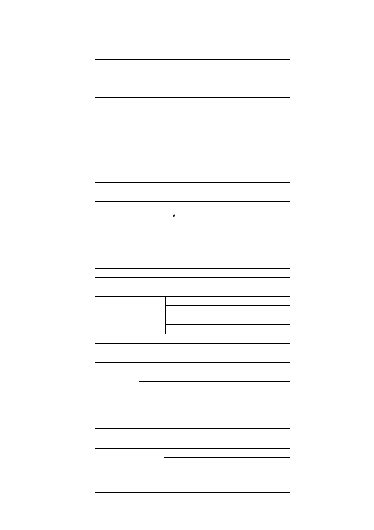
SPECIFICATIONS
TYPE COOLING COOLING & HEATING
INDOOR UNIT
OUTDOOR UNIT AOG36FNAXT AOG36UNAXT
COOLING CAPACITY
HEATING CAPACITY
(kW)
(kW)
ELECTRICAL DATA
POWER SOURCE
FREQUENCY
COOLING 6.20 5.90
RUNNING CURRENT
INPUT WATTS
E.E.R. (kW/kW)
STARTING CURRENT (A) 37
MOISTURE REMOVAL
(A)
HEATING ------- 6.20
COOLING 3.74 3.48
(kW)
HEATING ------- 3.65
COOLING 2.81 3.02
HEATING ------- 3.23
( /hr)
AUG36FUAS AUG36UUAS
10.5 10.5
------- 11.80
3N 400V
50Hz
4.0
COMPRESSOR
TYPE
DISCRIMINATION 5JD420PAA02
REFRIGERANT R410A (g) 2,000 3,200
HIGH 560
FAN SPEED
(r.p.m.)
AIR FLOW
DIMENSIONS
H x W x D (mm)
WEIGHT
[NET/GROSS] (kg)
MAX PIPE LENGTH / HEIGHT (m)
REMOTE CONTROLLER TYPE WIRED
(m3/h)
INDOOR
OUTDOOR 780
INDOOR 1,500 (HIGH)
OUTDOOR 7,000 6,100
INDOOR 296 x 830 x 830
GRILLE 35 x 940 x 940
OUTDOOR 1,165 x 900 x 330
INDOOR
OUTDOOR 80 / 87 94 / 101
MED 490
LOW 420
S-LOW 300
Hermetic type, 2 poles, 3 phase,
Induction motor, Twin Rotary
37 / 52
50 / 30
2005.08.01
ADDITIONAL REFRIGERANT CHARGE (R410A)
PIPE LENGTH
FULL CHARGE AMOUNT
ADDITIONAL CHARGE 30 g / m
20 m
30 m
40 m
50 m
2,000 g 3,200 g
2,300 g 3,500 g
2,600 g 3,800 g
2,900 g 4,100 g
1
Page 3
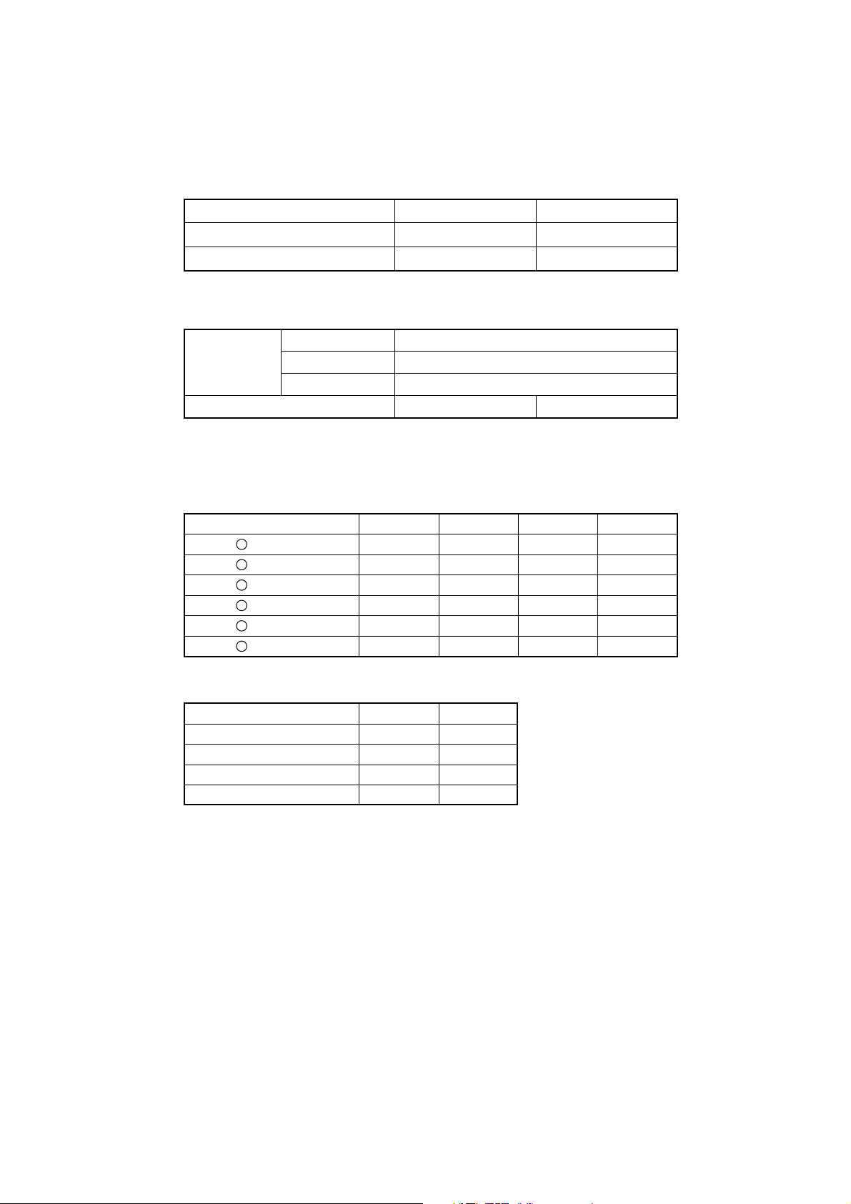
TYPE COOLING COOLING & HEATING
INDOOR UNIT
AUG36FUAS AUG36UUAS
OUTDOOR UNIT AOG36FNAXT AOG36UNAXT
NOISE LEVEL
HI-SPEED 48
INDOOR UNIT MED-SPEED (dB)
LO-SPEED
OUTDOOR UNIT
(dB)
(dB)
(dB)
44
41
54 COOL 54 / HEAT 55
HIGH CEILING MODE SELECTION (at 415V)
NUMBER of FAN REVOLUTION
1
580 ± 30 HIGH HIGH
2
550 ± 30 MED MED
3
510 ± 30 MED LOW HIGH
4
480 ± 30 LOW MED
5
440 ± 30 LOW LOW
6
300 ± 40 S-LOW S-LOW S-LOW S-LOW
(r.p.m) STANDARD HIGH CEILING2 HIGH CEILING2 LOW CEILING
HIGH
DIP - SW4 POSITION
SW NO.
SATNDARD
HIGH CEILING 1
HIGH CEILING 2
LOW CEILING
4-2 4-3
OFF OFF
ON OFF
OFF ON
ON ON
2005.08.01 2
Page 4
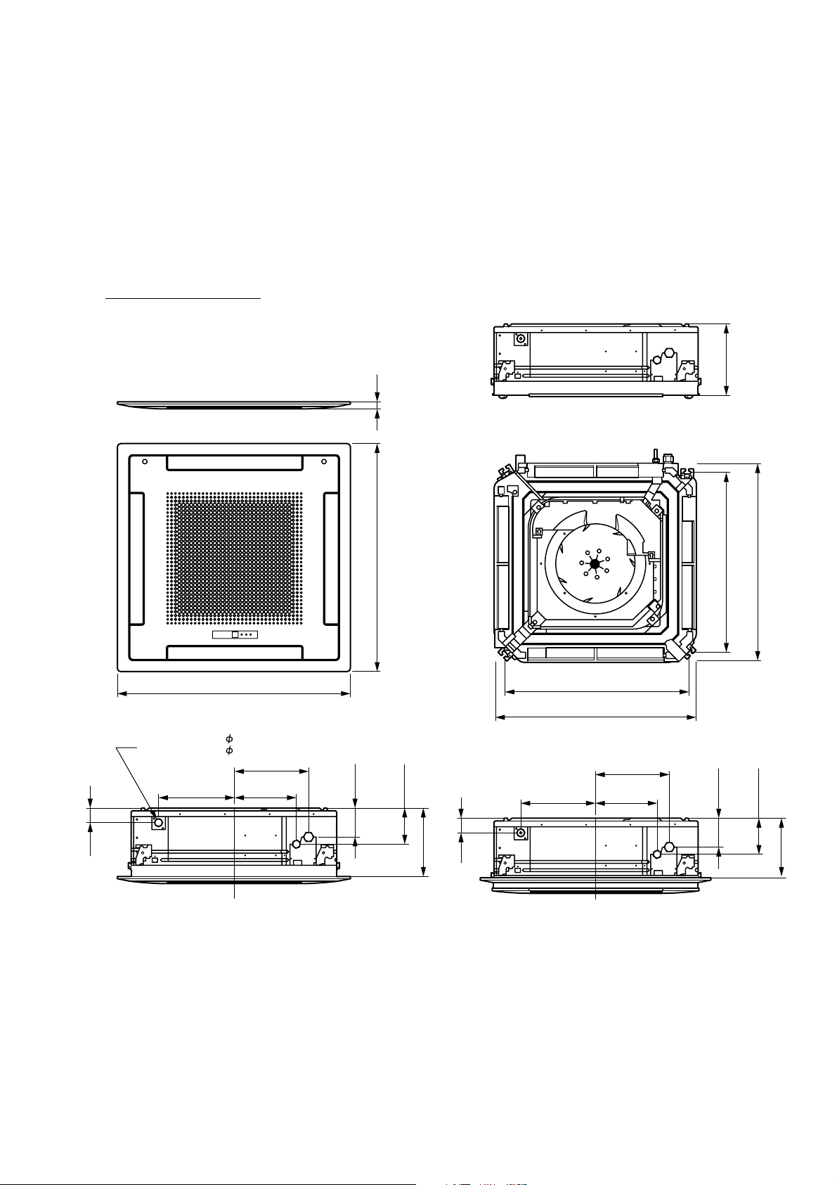
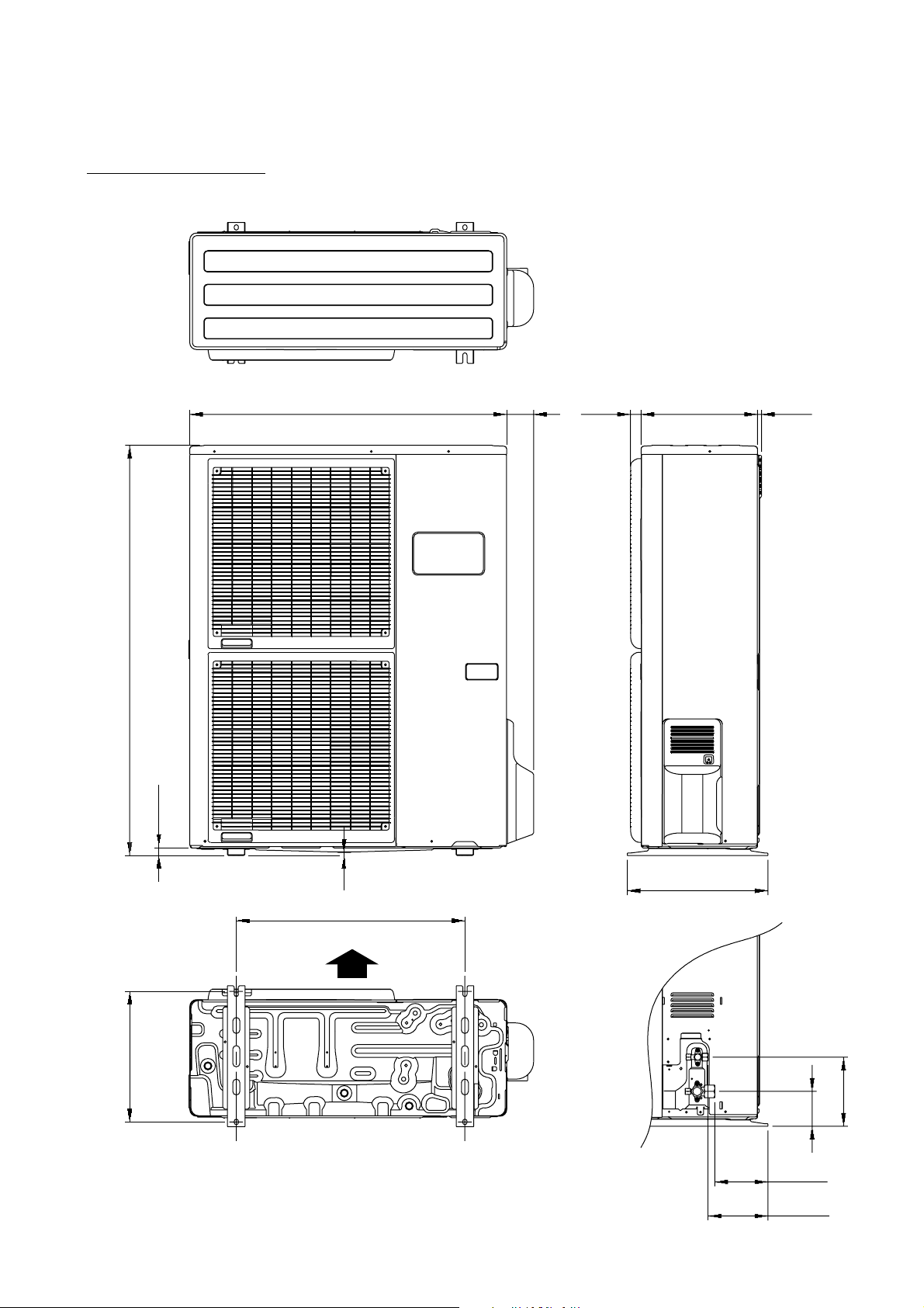
DIMENSIONS
(Unit : mm)
Models :
AUG36FUAS
AUG36UUAS
296
30
940
750
830
940
Inside
Drain
Outside
60
(Drain pipe)
Dia. 32
Dia. 37
298.5
305.5 248.5
120
(Large pipe)
(Small pipe)
150
60
285
(Drain pipe)
305.5
750
830
298.5
248.5
120
(Small pipe)
(Large pipe)
150
250
2005.08.01 3
Page 5
(Unit : mm)
Models :
AOG36FNAXT
AOG36UNAXT
3177900 330 12
1,165
21
9
650
400
Air Flow
370
196
99
2005.05.31 4
151
170
Page 6
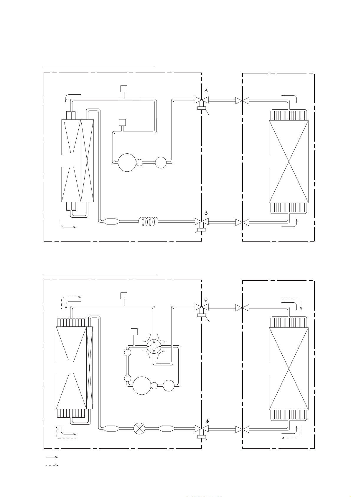
REFRIGERANT SYSTEM DIAGRAM
Models : AUG36FUAS / AOG36FNAXT
OUTDOOR UNIT
Condenser
High
Pressure
Switch
Compressor
Strainer
Pressure
Check Valve
Accumulator
Capillary
Tube
Charging Valve
Refrigerant Pipe
15.88mm (5/8")
Charging
Valve
Refrigerant Pipe
9.52mm (3/8")
INDOOR UNIT
Evaporator
Models : AUG36UUAS / AOG36UNAXT
OUTDOOR UNIT
Muffler
Condenser
Muffler
Strainer
Pressure
Check Valve
High
Pressure
Switch
4-way
Valve
Compressor
Expansion
Valve
Refrigerant Pipe
INDOOR UNIT
15.88mm (5/8")
Charging
Valve
Evaporator
Accumulator
Refrigerant Pipe
9.52mm (3/8")
Strainer
Charging Valve
: COOL
: HEAT
2005.05.31 5
Page 7
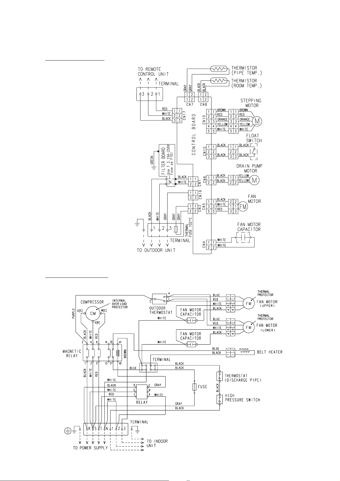
CIRCUIT DIAGRAM
Model : AUG36FUAS
Model : AOG36FNAXT
2005.05.31 6
Page 8
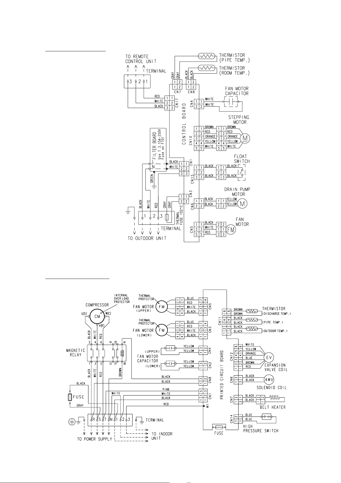
Model : AUG36UUAS
Model : AOG36UNAXT
2005.05.31 7
Page 9

INDOOR PCB CIRCUIT DIAGRAM
Model : AUG36FUAS
R5 62K
D5
1SR139-600
D10
1SR139-600
D3
K4 G5NB-1A
C105
0.022
<YE>
C106
0.022
<YE>
JM8JM5
VA2 470V
<TNR>
<RSP - 2W>
R6 100
<1/2W>
D1FL20U
C8
100/
+
6.3V
C101
0.22
D4
No.1
No.2
No.3
SW1
DSS803
THERMAL FUSE
GRAY
GRAY
CN3
53406-9910
POWER SOURCE
230V
50Hz
UL1015 AWG18 BLACK
UL1015 AWG18 WHITE
OUTDOOR UNIT
CN3-2
CN3-1
DRAIN PUMP
L
FH101
TM101
VA102 470V
<TNR>
N
TM102
E101
UL1015
AWG16
GREEN
FAN CAPACITOR
8.0 uF
400V
FAN MOTOR
TERMINAL BOARD
1
2
3
R1 3.3
<RGGS - 5W>
D1
D3SB60
YELLOW
M
YELLOW
F101 3.15A <BET>
FH102
SA101
RA-362M
W103
UL1015 AWG18 WHITE
CN4
B2P3-VH-B-Y
UL1015 AWG20 x 2
F M
UL1015 AWG22 x 3
E
R4 330K
<SPRH - 2W>
Q1
2SC4236
R3 100
<1/10W>
Q2
C5
+
100/
450V
UL1015 AWG22 x 2
2SC1815
R2 1.5
<RSP2 - 2W>
BLACK
BLACK
ELF20N018A
C102
0.22
LF101
VA101 470V
<TNR>
POWER SUPPLY PCB
W104
K01AL-040HWSE-P0
UL1015
CN1 B2P3-VH-B-C BLACK
AWG18
BLACK
WHITE
WHITE
BLACK
WHITE
RED CN5-3
CN1-1
CN1-2
YELLOW
CN4-1
CN4-2
CN5-1
CN5-2
CN5 B3P5-VH-B WHITE
C6 4700P
<ECQM>
C7 0.047
<ECQB>
D2
D1FL20U
MTZJ5.1B
R7
330
<1/4W>
CN6-2
C3 0.22 <RE>
R88 120 <1/2W>
CN6-1
CN6 B2P3-VH-B-E BLUE
C103
0.01
<KH>
C104
0.01
<KH>
UL1015 AWG18 GRAY
CUSTOM CODE SWITCHING
CUSTOM CODE SWITCHING
CUSTOM CODE SWITCHING
T1
SWITCHING TRANSFORMER
ZFT29B01
D6
D2FL20U
C9
+
1000
/25V
R8 10K
<1/10W>
SECONDARY
PRIMARY
C54
0.01 <F>
R11 56K
<1W>
I C9
TLP621
(D4) - GB
R13 10K
<1/10W>
5V
R39
AUTO RESTART
ROOM TEMPERATURE CORRECTION
( HEATING OPERATION )
ROOM TEMPERATURE CORRECTION
( HEATING OPERATION )
SSR1
G3MC-202PL-VD
+
-
CN19
B2P3-VH-B-R
RED
CN19-1
CR8
TA120033
K8
G5N-1A
JUMPER
SETTING
JM1
JM2
JM3
SW2
DRS4016-5
C
D8
D1F60
R38
TEST
5V
I C2
7812
IO
G
I C3
7805
IO
G
5V R29 - R32
8
4
2
1
5V
R12 1.0K
<1/10W>
10K <1/10W> x 3
R37
R42 1.0K <1/10W>
R41 1.0K <1/10W>
R40 1.0K <1/10W>
14V
R21 - R24
10K <1/10W> x 4
CN9-1
CN9-2
CN9-3
CN9-4
CN9-5
R15 - R17
10K <1/10W> x 3
R18 1.0K <1/10W>
R19 1.0K <1/10W>
R20 1.0K <1/10W>
12V14V
C11
+
10/
25V
C13
0.1
<F>
10K <1/10W> x 4
C26 - C29
0.01 <F> x 4
C17
C18
0.01
0.01
<F>
<F>
K 4
5V
C19 - C21
0.01 <F> x 3
10K <1/10W> x 4
R59 R97
C14
+
100/
6.3V
R33 - R36
1.0K <1/10W> x 4
5V
R10 10K
<1/10W>
Q3
DTC124EKA
C10
0.01 <F> x 3
R93 - R96
10K <1/10W> x 4
14V
9
11
6
12
5
13
4
3
14
15
2
8
R25 - R28
1.0K <1/10W> x 4
C22 - C25
0.01 <F> x 4
I C5 (1/7)
uPA2003GR
10
I C11-1
BA10358
1
CN9
B5P-SHF-1AA
R98
R99
C15
0.1
<F>
NC
R9 390
<1/10W>
C12
C30
I C5 (5/7)
uPA2003GR
7
3
+
2
-
5V
C47
0.1
<F>
JM10
CR6
0.01
<F>
5V
1
2
3
54
55
66
65
74
68
75
7
4
67
33
71
72
56
57
58
59
63
19
20
21
40
39
38
37
36
43
44
45
46
41
P15
P16
P17
I C 1
uPD780058BGC
-108-8BT
P122
P123
P05
P04
VDD0
VDD1
AVRF 0
AVRF 1
AVSS
VSS0
VSS1
I C
XT2
P124
P125
P126
P127
P02
P40
P41
P42
P64
P63
P62
P61
P60
P67
P30
P31
P32
P65
X1 X2
70
1
2
P10
P11
P70
P71
P72
P131
P46
P24
P23
P47
P57
P56
P50
P27
P26
P25
P22
P21
P20
P130
P00
P121
P36
P33
P01
P55
P34
P37
P35
P120
P03
P12
P13
P14
P66
P52
P53
P54
P45
P44
P43
XT1
P51
RESET
69
3
X1
CSTS0500MG03-T
76
C32
1000P
<R>
77
C35
1000P
<R>
8
9
10
6
R77 R78 R79
25
15
14
26
35
34
27
18
17
16
13
12
11
5
61
53
I C6 (2/7)
uPA2003GR
50
11
6
47
161
5V
C41
+
10/
25V
62
CR5
1000P
<R>
32
48
51
49
52
64
78
79
80
42
29
NC
30
NC
31
NC
24
23
22
C31 C16 C43
0.01 <F> x 3
73
28
60
NC
R55
10K
<1/10W>
C44
0.1
<F>
5V
R44 1.0K
<1/10W>
R46 1.0K
<1/10W>
R50 10K <1/10W>
4
DO
3
D I
2
CK
15
CS GND
I C7
BR93L46RF
10K <1/10W> x 3
R58 10K <1/10W>
R75 10K <1/10W>
R76 10K <1/10W>
R100 10K <1/10W>
16
1
10
7
5
14V
9
41213
2
I C4 (7/7)
uPA2003GR
R56
BZ1
PKM13EPY-4000
C42
0.01
<F>
R54 47
<1/10W>
C40
0.01 <F>
CR1 - CR4
10K <1/10W>
x 4
R81 1.0K <1/10W>
R72 1.0K <1/10W>
R71 1.0K <1/10W>
RJ1 1.0K
<1/10W>
C49
0.01
<F>
15
R57 1.0K
<1/10W>
CR7
0.01
<F>
RJ2
10K
<1/10W>
I C8
PST600C
11
6
314
16
1
8
B Z
R53 10K
<1/10W>
R70 R69 R80
5V
5V
1
3
2
5V
VCC
8
NC
7
C39
0.1
NC
6
<F>
5V
I C5 (1/7) uPA2003GR
NC
NC
5V
NC
R60
NC
10K
<1/10W>
Q5
2SC2712
14V
5V
R51 1.0K
<1/10W>
215
13
4
3
14
5
12
5V
10K <1/10W>
x 3
SW4
DSS803
FAN DELAY CHANGE
No.3
( HEATING OPERATION )
No.2
FAN TYPE CHANGE
REMOTE TYPE CHANGE
No.1
CN15-1
CN15-2
CN15-3
CN15 B3B-XARK-1-A RED
C45
0.1
<F>
R43 10K
<1/10W>
(1%)
R45 49.9K
<1/10W>
(1%)
Q4
DTC124EKA
14V
R61
10K
<1/10W>
3
1
Q6
2
2SC2712
7
K 8
I C6 (4/7)
uPA2003GR
R67 1.0K
<1/10W>
No.3
No.2
No.1
UL1430 AWG22
UL1430 AWG22
C34
0.1
<F>
C37
0.1
<F>
R49 1.0K
<1/10W>
C38
0.01
<F>
UL1430 AWG28 x 5
CN10-1
CN10-2
CN10-3
CN10-4
CN10-5
CN10
B5B-XASK-1-A
5V
3
2
I C6 (1/7)
uPA2003GR
R65 390 <1/10W>
10
5V
R52
10K
<1/10W>
14V
R68 10K
<1/10W>
C1 0.1
<F>
5V
R47 390
<1/10W>
5V
R48
10K
<1/10W>
BROWN
RED
ORANGE
YELLOW
WHITE
R63 15.4K
<1/10W>
(1%)
R62 4.7K
1
<1/10W>
(1%)
I C11-2
BA10358
5V
CN14
B4B-XH-AM
CN14-4
CN14-3
CN14-2
CN14-1
5V
CN8 B2B-XASK-1-A
CN7 B2B-XAKK-1-A
HA
JEM-A
CN8-1 BLACK
CN8-2 BLACK
CN7-1 GRAY
CN7-2 GRAY
BLACK
Jumper 1,2,3 setting
Remote control unit custom code switching
JP3 JP2 JP1
ROOM TEMPERATURE THERMISTOR
PIPE TEMPERATURE THERMISTOR
Wireless
remote
control unit
on on on
off
on
off
on
off
on
off
off
on
on
off off
on
on
off
off
on
on
offoffoff
BROWN
RED
12V
ORANGE
YELLOW
WHITE
R64 28K
<1/10W>
(1%)
12V
+7
-
D7
DA226U
12V
L2 0.022
<DSS306>
3
1
2
12V
R66 10K
<1/10W>
31
L4 0.022
<DSS306>
L3 0.022
2
<DSS306>
5
6
M
CN17 B3B-XAKK-1-A
CN17-1
CN17-2
1
3
2
CN17-3
LOUVER
( UP / DOWN )
UL1430 AWG22 RED
UL1430 AWG22 WHITE
UL1430 AWG22 BLACK
TERMINAL BOARD
Room temp. heating correction
SW1-3 SW1-2 Correction
off
off
0 ( +2 deg. )
onoff
on
on
1 ( -2 deg. )
off
2 ( o deg. )
on
3 ( +4 deg. )
SW1 & SW4
SW1-1
Auto restart
Remote control unit type change *1SW4-1
SW4-2
Fan type change
SW4-3
Fan delay change (heating operation)
*1
In the normal mode,
it works as EEPROM model information "wired / wireless switching" shows.
In the reversal mode, it reverses that information.
BLACK
BLACK
FLOAT SWITCH
reversal
"with thermistor" type
A (00)
B (01)
C (10)
D (11)
A (00)
B (01)
EZ-098YHSE-R series
C (10)
EZ-09503HSE-R series
D (11)
REMOTE CONTROL UNIT
on offSW Function
on
off
normal
-
delay
no delay
3
-
Wired
remote
control unit
weekly type
weekly type
weekly type
weekly type
weekly type
21
2005.08.01 8
Page 10

Model : AUG36UUAS
THERMAL FUSE
GRAY
GRAY
CN3-2
CN3-1
CN3
53406-9910
L
FH101 FH102
TM101
POWER SOURCE
230V
50Hz
N
TM102
UL1015 AWG16
GREEN
FAN CAPACITOR
8.0uF
400V
FAN MOTOR
UL1015 AWG18 RED
UL1015 AWG18 BLACK
UL1015 AWG18 WHITE
TERMINAL BOARD
1
2
3
OUTDOOR UNIT
<BET>
F101
3.15A
VA102 470V
<TNR>
E101
F. M.
E
R1 3.3
<RGGS - 5W>
D1
D3SB60
SA101
RA-362M
W103
UL1015 AWG18 WHITE
UL1015 AWG18 RED
UL1015 AWG20 WHITE
UL1015 AWG20 WHITE
UL1015 AWG20 BLACK
UL1015 AWG20 WHITE
UL1015 AWG20 RED
C5
+
100/
450V
VA101 470V
<TNR>
W104
UL1015 AWG18
BLACK
DRAIN PUMP
M
C6 4700P
<ECQM>
R4 330K
<SPRH - 2W>
Q1
2SC4236
R3 100
<1/10W>
Q2
2SC1815
R2 1.5
<RSP2 - 2W>
C7 0.047
<ECQB>
D2
D1FL20U
D3
MTZJ5.1B
R7
330
<1/4W>
ELF20N018A
C103
0.01
LF101
<KH>
C104
0.01
<KH>
C102
0.22
POWER SUPPLY PCB
K01AL-040GHSE-P0
CN1-1
CN1-2
CN1-3
CN1
B3P5-VH-B-C
BLACK
CN4
B2P3-VH-B-Y
YELLOW
CN4-1
CN4-2
CN5-1
CN5-2
JM5 JM8
CN5-3
CN5 B3P5-VH-B
UL1015 AWG22
BLACK
YELLOW
UL1015 AWG22
BLACK
YELLOW
D5
1SR139-600
D10
1SR139-600
R6 100
<1/2W>
D4
D1FL20U
C8
100/
+
6.3V
C105
0.022
<YE>
C101
0.22
C106
0.022
<YE>
CN6-2
CN6-1
CN6
B2P3-VH-B-E
BLUE
SW1
DSS803
No.1
No.2
No.3
ROOM TEMPERATURE CORRECTION
( HEATING OPERATION )
ROOM TEMPERATURE CORRECTION
( HEATING OPERATION )
R5 62K
<RSP2 - 2W>
SWITCHING TRANSFORMER
PRIMARY SECONDARY
K4
G5NB-1A
C3 0.22 <RE>
R88 120 <1/2W>
TEST
CN9
B5P-SHF-1AA
ZONE CONTROL
CUSTOM CODE SWITCHING
CUSTOM CODE SWITCHING
CUSTOM CODE SWITCHING
T1
ZFT29B01
VA1 470V
<TNR>
18
14
10
SSR1
G3MC-202PL-VD
VA2 470V
<TNR>
CN9-1
CN9-2
CN9-3
CN9-4
CN9-5
R39 R38 R37
D6
D2FL20U
C54
0.01
<F>
5V
5V
R8 10K
<1/10W>
I C11-1
BA10358
JM1
JM2
JM3
14V
C9
+
1000
/25V
SW2
DRS4016-5
C1
I C 10 H I 2002
R93 - R96
10K <1/10W> x 4
+
-
R21 - R24
5V
10K <1/10W> x 4
10K <1/10W> x 3
1
5V
R15 - R17
10K <1/10W> x 3
I C2
12V
7812
IO
G
C11
+
10/
25V
I C3
7805
IO
G
5V
8
4
2
5V
C13
0.1
<F>
R29 - R32
10K <1/10W> x 4
R33 - R36
1.0K <1/10W> x 4
C26 - C29
0.01 <F> x 4
5V
1
4
C17
0.01
<F>
14V
NC
NC
NC
K 4
R25 - R28
1.0K <1/10W> x 4
C22 - C25
0.01 <F> x 4
R42 1.0K <1/10W>
R41 1.0K <1/10W>
R40 1.0K <1/10W>
3
+
2
-
CONTROLLER PCB ASSEMBLY ( MAIN PCB )
K01AL-040MHSE-C1
R18 - R20
1.0K <1/10W> x 3
C19 - C21
0.01 <F> x 3
10K <1/10W> x 4
R59 R97 R98 R99
C15
C14
+
0.1
100/
<F>
6.3V
NC
10
7
I C5 (1/7)
uPA2003GR
R14 10K
5
<1/10W>
2
3
5V
R10
10K
<1/10W>
11
12
13
14
1582
Q3
DTC124EKA
14V
9
6
5
4
3
I C5 (5/7)
uPA2003GR
R9 390
<1/10W>
1
P15
2
P16
3
P17
I C 1
uPD780058BGC
-0108-8BT-A
54
P122
55
P123
66
P05
65
P04
74
VDD0
68
VDD1
75
AVRF 0
7
AVRF 1
C47
0.1
<F>
AVSS
4
67
VSS0
33
VSS1
JM10
71
I C
72
XT2
56
P124
57
P125
58
P126
59
P127
41
P65
42
CR1
0.01
<F>
0.01 <F> x 3C10 C12 C30
P66
63 P02
CR6
0.01
<F>
40
P64
39 P63
38
P62
3736P61
P60
43
P67
44
P30
45
P31
46
P32
19
P40
20
P41
21
P42
X1 X2
70
13
2
76
P10
77
P11
P70 8
9
P71
10P72
6
P131
25
P46
15
P24
14
P23
P47
26
35
P57
34
P56
27
P50
18
P27
17
P26
16
P25
13
P22
12
P21
11
P20
5
P130
61
P00
53P121
P36
P33
47
C41
10/
25V
62P01
32P55
52
P120
51P37
49P35
48
P34
64
P03
78
P12
79
P13
80
P14
29P52
30
P53
31
P54
P45
24
P44 23
22P43
C31 C16 0.01 <F> x 3
73
XT1
28
P51
NC
60
RESET
69
X1
CSTS0500MG03-T
6
CR5
1000P
<R>
NC
NC
NC
R55
10K
<1/10W>
C32
1000P
<R>
C32
1000P
<R>
16111
I C6 (2/7)
uPA2003GR
5V
+
C44
0.1
<F>
R54 47
<1/10W>
C43
5V
R44 1.0K
<1/10W>
R46 1.0K
<1/10W>
R50 10K <1/10W>
DO
4
3
D I
CK
2
1
CS
I C7
BR93L46RF
R77 - R79
10K <1/10W> x 3
R58 10K <1/10W>
R75 10K <1/10W>
R76 10K <1/10W>
R100 10K <1/10W>
1
710
611
512
14V
9
13
4
314
152
116
8
I C4 (7/7)
uPA2003GR
R57 1.0K
<1/10W>
R56
B. Z.
BZ1
PKM13EPY-4000
C42
I C6 (1/7)
0.01
uPA2003GR
<F>
R53 10K
<1/10W>
5
12
4
13
3
14
2
15
CR7
0.01
<F>
CR2 - CR4
10K <1/10W>
x 3
1.0K <1/10W> x 3
R81
R72
R71
RJ1 1.0K
<1/10W>
C49
0.01
<F>
3
I C8
PST600C
5V
8
VCC
7
NC
C39
0.1
6
NC
<F>
5
GND
5V
I C5 (1/7) uPA2003GR
16
NC
NC
NC
R60
NC
10K
<1/10W>
Q5
2SC2712Q62SC2712
14V
710
5V
C40
0.01
<F>
I C6 (4/7)
uPA2003GR
R70
R69
5V
5V
1
2
RJ2
10K
<1/10W>
C45
0.1
<F>
No.3 FAN CHANGING
No.2 FAN CHANGING
No.1 ROOM TEMP. CORRECTION
( COOLING OPERATION )
CN15-1
CN15-2
CN15-3
R43 10K
<1/10W>
(1%)
R45 49.9K
<1/10W>
(1%)
Q4
DTC124EKA
R49 1.0K
<1/10W>
C38
0.01
<F>
14V
CN10-1
CN10-2
CN10-3
CN10-4
CN10-5
CN10
B5B-XASK-1-A
5V
R61
10K
<1/10W>
3
1
2
5V
5V
R51 1.0K
<1/10W>
R67 1.0K
<1/10W>
R68 10K
<1/10W>
5V
10K <1/10W>
R80
x 3
SW4
DSS803
No.3
No.2
No.1
UL1430 AWG22
UL1430 AWG22
CN15 B3B-XARK-1-A
RED
C34
0.1
<F>
C37
CN14
0.1
B4B-XH-AM
<F>
5V
R47 390
<1/10W>
5V
R48
10K
<1/10W>
BROWN
RED
ORANGE
YELLOW
WHITE WHITE
UL1430
AWG28
R63 15.4K
<1/10W>
(1%)
3
1
R62 4.7K
2
<1/10W>
R65 390
<1/10W>
R52
10K
<1/10W>
5V
C1
0.1
<F>
5V
CN8 B2B-XASK-1-A
CN8-1 BLACK
CN8-2 BLACK
CN7 B2B-XAKK-1-A BLACK
CN7-1 GRAY
CN7-2 GRAY
ROOM TEMPERATURE THERMISTOR
PIPE TEMPERATURE THERMISTOR
CN14-4
CN14-3
CN14-2
CN14-1
HA
JEM-A
Jumper 1,2,3 setting
Remote control unit custom code switching
JP3 JP2 JP1
on on on
off
on
off
on
off
on
off
off
on
on
off off
on
on
off
off
on
on
offoffoff
BROWN
12V
I C11-2
BA10358
12V
7
D7
DA226U
RED
ORANGE
YELLOW
R64 28K
<1/10W>
(1%)
5
+
6
12V
12V
L2 0.022
<DSS306>
3
R66 10K
<1/10W>
1
2
L4 0.022
<DSS306>
3
2
1
L3 0.022
<DSS306>
M
2
13
CN17-1
CN17-2
CN17-3
LOUVER
( UP / DOWN )
CN17
B3B-XAKK-1-A
UL1430 AWG22 RED
UL1430 AWG22 WHITE
UL1430 AWG22 BLACK
TERMINAL BOARD
Room temp. heating correction
SW1-3 SW1-2 Correction
off
off
0 ( +2 deg. )
onoff
on
on
1 ( -2 deg. )
off
2 ( o deg. )
on
3 ( +4 deg. )
SW1 & SW4
SW1-1
Auto restart
Remote control unit type change *1SW4-1
SW4-2
Fan type change
SW4-3
Fan delay change (heating operation)
*1
In the normal mode,
it works as EEPROM model information "wired / wireless switching" shows.
In the reversal mode, it reverses that information.
FLOAT SWITCH
BLACK
BLACK
reversal
Wireless
remote
control unit
A (00)
B (01)
C (10)
D (11)
A (00)
B (01)
C (10)
D (11)
REMOTE CONTROL UNIT
on offSW Function
on
off
normal
-
delay
no delay
Wired
remote
control unit
"with thermistor" type
weekly type
weekly type
weekly type
weekly type
weekly type
EZ-098YHSE-R series
EZ-09503HSE-R series
321
-
2005.08.01 9
Page 11

OUTDOOR PCB CIRCUIT DIAGRAM
Model : AOG36UNAXT
R1 3.3
INDOOR UNIT
E
TERMINAL
3
2
1
N
T
S
R
E
POWER SOURCE
415 / 380V
50Hz
MAGNETIC
RELAY
UL1015 AWG22 RED
WHITE
UL1015 AWG18
BLACK
UL1015 AWG18
UL1015 AWG14 BLACK
UL1015 AWG14 WHITE
UL1015 AWG14 RED
R
S
TN
COMP.
A
COMPRESSOR-A
<RC - 5W>
CN1
B3P5-VH-B-C
BLACK
UL1015 AWG22 WHITE
UL1015 AWG22 BLACK
UL1015 AWG18
GRAY
UL1015 AWG16 BROWN
UL1015 AWG22 PINK
4
CN1-1
CN1-2
CN1-3
D8
2
D3SB60
1
3
C12
+
1000
/450V
<BET>
FH1
W1
FAN CAPACITOR-1
MOTOR
250V
FAN CAPACITOR-2
5A
MOTOR
4-WAY VALVE
BELT HEATER
R2 330K
<2W>
Q1
2SC4236
2
1
3
R5 10K
<1/10W>
Q2
2SC1815
R6 1.5
<RS - 2W>
F1
6.3A
FH2
BLACK
WHITE
FAN
1
RED
BLUE
BLACK
WHITE
FAN
2
RED
BLUE
UL1015 AWG20 BLACK
UL1015 AWG20 BLACK
2
1
3
VA1
470V
UL1015 AWG20
UL1015 AWG20
UL1015 AWG20
UL1015 AWG20
UL1015 AWG20
UL1015 AWG20
UL1015 AWG20
UL1015 AWG20
UL1015 AWG20
UL1015 AWG20
UL1015 AWG20
UL1015 AWG20
4WV
C13
4700P
<ECQM>
D2
1SR139-600
D5
D1FL20U
C14 0.047
<ECQB>
D6
MTZJ5.1B
R7 330
<1/4W>
VA3
470V
YELLOW
YELLOW
BLACK
WHITE
RED
BLUE
YELLOW
YELLOW
BLACK
WHITE
RED
BLUE
CN6-2
BLACK
CN6-1
BLACK
UL1015 AWG20
BLACK
UL1015 AWG20
BLACK
C1
0.22
R3 62K
<RS - 2W>
R4 100
<1/2W>
D4
D1FL20U
C15
100/
+
6.3V
LF1
0.5A
<SS11V>
CN2
B2P3-VH-B-Y
YELLOW
CN2-1
CN2-2
CN3
B4P7-VH-B-R
RED
CN3-1
CN3-2
CN3-3
CN3-4
CN4
B2P3-VH-B-Y
YELLOW
CN4-1
CN4-2
CN5
B4P7-VH-B
WHITE
CN5-1
CN5-2
CN5-3
CN5-4
CN6
179844-1
WHITE
C8 0.22
R60 120
<1/2W>
CN7
179844-4
YELLOW
CN7-2
CN7-1
CN8
B2P3-VH-B-R
RED
CN8-1
CN8-2
T1
ZFT19K01
1
2
3
4
5
SWITCHING
TRANSFORMER
C11
0.01
<F>
C2
0.22
C6 0.22
R58 120
<1/2W>
K2
K1
G5S-1
FTR-F3A
C7 0.22
R59 120
<1/2W>
K3
K4
FTR-F3A
G5S-1
K5
FTR-F3A
K6
FTR-F3A
K7
FTR-F3A
CONTROLLER PCB ASSEMBLY
K04DF-0402HUE-C1
24
VDD1
10
VDD0
NC
5V
R40 1.0K
<1/10W>
C33
1000P
<R>
3
2
C38
0.1
<F>
C31
0.01
<F>
34
38
42
25
9
35
5V
43
23
18
1
AVRE F
XT1
GND1
AGND
GND0
AVDD
I C 1
uPD780076GK
-649-9ET-A
P00
P25
P20
RESET
5V
+
3
R39
2
10K
<1/10W>
Q4
DTC124EKA
C37
0.1
<F>
R37 4.7K
<1/10W>
C36
100/
6.3V
10
7
D7
S3L20U
14
10
18
+
C10
1000
/25V
14V
R8
10K
<1/10W>
I C 6 HU2001
I C2
7805
O
I
G
R38 4.7K
<1/10W>
5V
C16
0.1
<F>
5V
Q3
DTC124EKA
2
1
C32
3
0.1
<F>
1
5V
5
4
5V
C5
14V
0.22
R16 56K
<RS - 1W>
D1
D1F60
K 2
K 1
K 4
K 3
K 6
K 5
K 7
16
14
12
10
1
2
PC1
TLP621
<GB>
14V
4
3
I C3-1 uPA2003
1
15
I C3-3 uPA2003
3
13
5
I C3-5 uPA2003
11
I C3-7 uPA2003
7
5V
R9
4.7K
<1/10W>
C26
0.01
<F>
I C3-2 uPA2003
2
I C3-4 uPA2003
4
I C3-6 uPA2003
6
1
Q5
DTC124EKA
R10
4.7K
<1/10W>
3
2
NC
NC
NC
NC
NC
NC
NC
NC
NC
C25
0.01
<F>
19
45
37
20
63
62
61
60
59
58
57
P21
P02
XT2
P22
7
P56
8
P57
P46
P45
P44
P43
P42
P41
P40
2
P51
4
P53
P54
5
P55
6
1
P50
3
P52
X1 X2
41 40
1
P67
P66
P65
P64
P75
P74
P73
P72
P03
P71
P10
P70
P01
P17
P47
I C
P24
P23
P16
P34
P35
P36
P30
P31
P32
P33
P11
P12
P13
P14
P15
3
I C4-7 uLN2003
56
I C4-6 uLN2003
55
54
I C4-5 uLN2003
53
I C4-4 uLN2003
I C4-3 ULN2003
52
51
NC
50
NC
49
NC
46
48
C40
0.1
<F>
R52 1.0K
<1/10W>
33
C41
0.1
<F>
47
44
26
64
5V
36
JM4
39
22
21
27
15
16
17
11
12
NC
13
NC
14
NC
32
31
30
29
28
C24 C21C22C23
R46 10K
<1/10W>
C27
R41
10K
<1/10W>
C34
0.1
<F>
R54 10K <1/10W>
R55 10K <1/10W>
R43 - R45
10K <1/10W> x 3
14V
10
7
611
512
13
4
3
14
R50 1.0K
<1/10W>
5V
R53 10K
<1/10W>
C43
0.1
<F>
R31
C30 C29 C28
0.01 <F> x 4
I C8
BD4742G
2
SUBNCVCC
VOUT
1
GND
NC
5V
8
1
CS
VCC
2
SK
DO
4
D I
NC
3
7
NC
5
6
GND
NC
I C7
NM93C46
C39
0.01
<F>
R11 1.0K <1/10W>
R12 1.0K <1/10W>
R13 1.0K <1/10W>
R14 1.0K <1/10W>
R15 1.0K <1/10W>
1000P <R> x 4
5V
R51
10K
<1/10W>
C42
0.1
<F>
5V
10K <1/10W> x 4
R33 R36
R32
R29
R30
1.0K <1/10W> x 4
5V
5
C35
4
0.1
3
<F>
5V
R42 10K
<1/10W>
C44
NC
0.1
<F>
R21 1.0K <1/10W>
CN14
B2P-VH-B
WHITE
R35R34
14V
CN12
B6B-XASK-1-A
WHITE
CN12-1 UL1430 AWG24 RED
CN12-2 UL1430 AWG24 BROWN
CN12-3 UL1430 AWG24 BLUE
CN12-4 UL1430 AWG24 ORANGE
CN12-5 UL1430 AWG24 YELLOW
CN12-6 UL1430 AWG24 WHITE
DIP-SW setting
Function on off
SW1-1
Expansion valve first pulse switching for long piping
SW1-2
Spare
SW1-3
Spare
CN14-1 UL1015 AWG20
CN14-2 UL1015 AWG20
6
1
5
2
43
SW1
DSS803
5V
R22
10K
<1/10W>
C20
BLUE
PRES.
BLUE
SW
EXPANSION VALVE
FIRST PULSE SWITCHING
FOR LONG PIPING (E.E.V.)
SPARE
SPARE
5V
5V
C18C17
C19
E.E.V.
ELECTRIC EXPANSION VALVE
HIGH PRESSURE SWITCH
CN11
B6B-XAKK-1-A
BLACK
CN11-1 BLACK
CN11-2 BLACK
CN11-3 BLACK
CN11-4 BLACK
CN11-5 BROWN
CN11-6 BROWN
Long piping mode
---
---
OUTDOOR TEMP.
THERMISTOR
TUBE
BLACK
BLACK
BLACK
R25=10.00K
B25/50=3950K
Normal mode
---
---
PIPE TEMP.
R0=16.05K
B0/25=3873K
DISCHARGE TEMP.
R100=3.43K
B50/100=4012K
0.1 <F> x 4
2
EF0EC8384T4
X1
8.38MHz
R19 6.65K (1%)<1/10W>
R17 38.3K (1%)<1/10W>
R18 14K (1%)<1/10W>
R20 6.65K (1%)<1/10W>
5V
R23 10K <1/10W>
R25 10K <1/10W>
LED1 EBR3864 <RED>
LED2 EBR3864 <RED>
2005.08.01 10
Page 12

ERROR CONTENTS
(1) Stop the air conditioner operation.
(2) Press the master control button and the fan control button si-
multaneously for 2 seconds or more to start the test run.
Test run display
(3) Press the start/stop button to stop the test run.
[SELF-DIAGNOSIS]
When the error indication "E:EE" is displayed, follow the following
items to perform the self-diagnosis. "E:EE" indicates an error has
occurred.
1. REMOTE CONTROLLER DISPLAY
(1) Stop the air conditioner operation.
(2) Press the set temperature buttons simultaneously for 5
seconds or more to start the self-diagnosis.
Refer to the following tables for the description of each error
code.
Unit number (usually 0)
SUMOTUWETH FR
EX. Self-diagnosis
(3) Press the set temperature buttons simultaneously for 5
seconds or more to stop the self-diagnosis.
Error code Error contents
00
01
02
03
04
05
06
07
08
09
0A
0b
0c
0d
0E
0F
11
12
13
14
Communication error
(indoor unit
Communication error
(indoor unit
Room temperature sensor open
Room temperature sensor short-circuited
Indoor heat exchanger temperature sensor open
Indoor heat exchanger temperature sensor shortcircuited
Outdoor heat exchanger temperature sensor
open
Outdoor heat exchanger temperature sensor
short-circuited
Power source connection error
Float switch operated
Outdoor temperature sensor open
Outdoor temperature sensor short-circuited
Discharge pipe temperature sensor or compressor
temperature sensor open
Discharge pipe temperature sensor or compressor
temperature sensor short-circuited
Outdoor high pressure abnormal
Discharge pipe temperature or compressor
temperature abnormal
Model abnormal
Indoor fan abnormal
Outdoor signal abnormal
Outdoor EEPROM abnormal
remote controller)
outdoor unit)
Error code
SA
2. OUTDOOR UNIT LEDS
Heat & Cool model (reverse cycle) only
When a malfunction occurs in the outdoor unit, the LEDs on the circuit board
light to indicate the error. Refer to the
following table for the description of
each error according to the LEDs.
LED1 LED2 Error contents
flash
1flash
2 flash
3 flash
4 flash
5 flash
6 flash
7 flash
8 flash
9 flash
10 flash
Dislighting
When the fault is cleared, the LED lamp goes off.
However, for discharge pipe temperature abnormal and high pressure abnormal, the LED lamp lights continuously for 24 hours, as
long as the power is not turned off.
flash
Lighting
Lighting
Lighting
Lighting
Lighting
Lighting
Lighting
Lighting
Lighting
Lighting
Model abnormal or EEPROM abnormal
Power source connection error
Discharge temp. sensor error
Heat exchanger temp. sensor error
Outdoor temp. sensor error
Communication signal error
Indoor unit error
Discharge temp. abnormal
High pressure abnormal
Compressor temp. abnormal
Compressor temp. sensor error
No error. Protect operation
LED layout
LED2
LED1
2005.05.31 11
Page 13

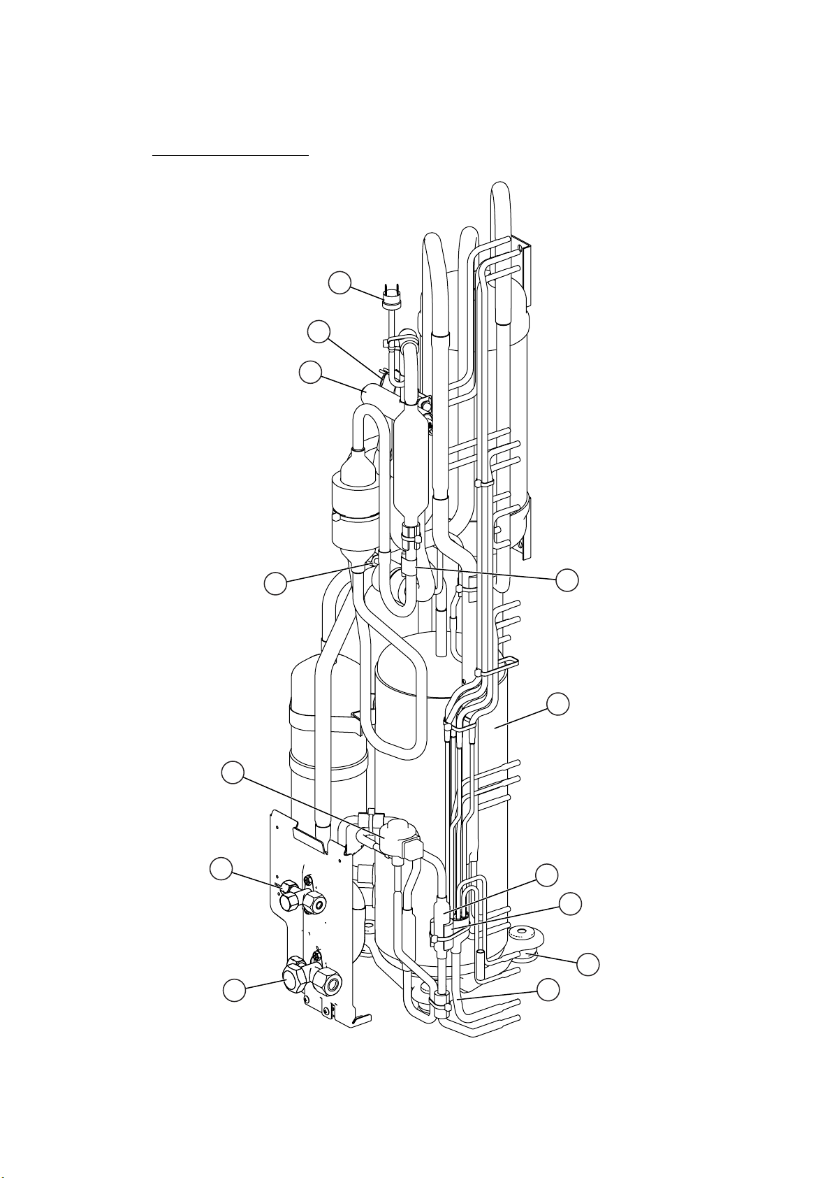
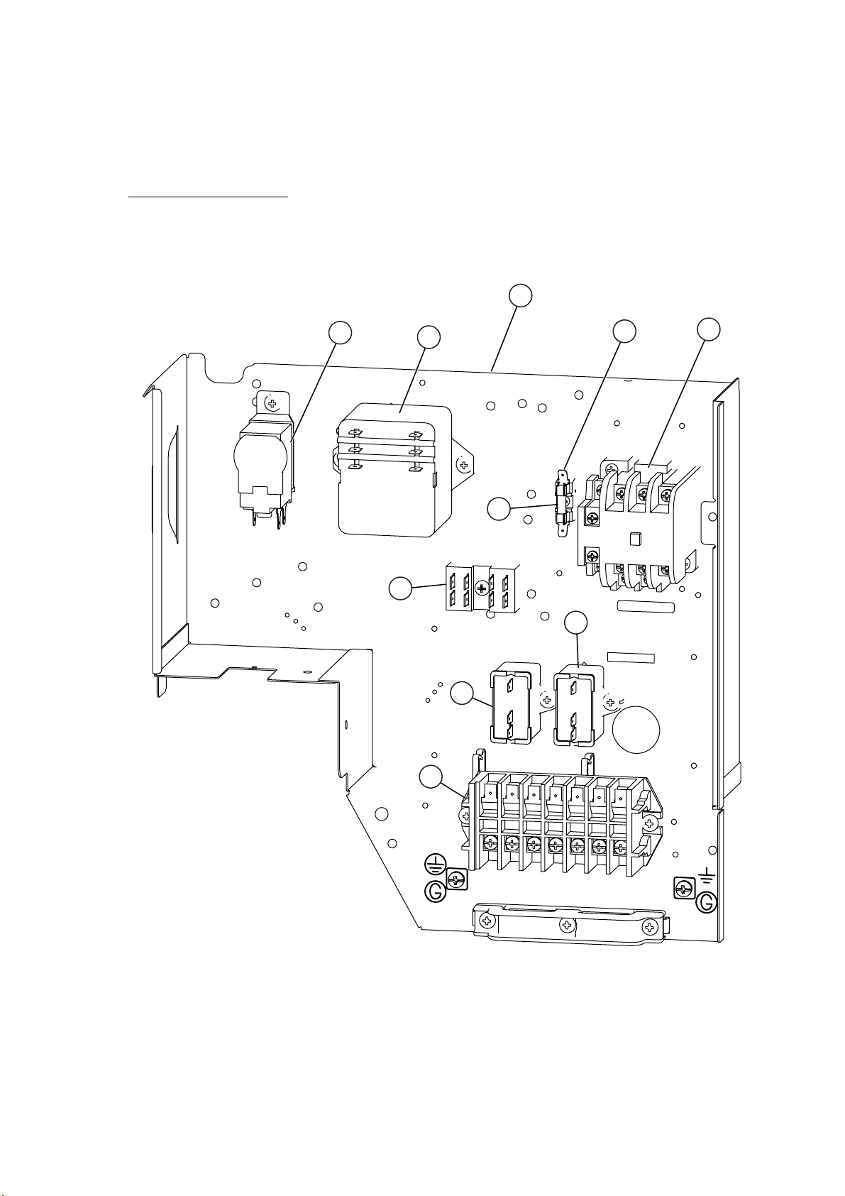
DISASSEMBLY ILLUSTRATION
Models : AUG36FUAS
AUG36UUAS
847
692
690
692
847
834-2
705
543
692
122
847
122
690
544
543
544
847
122
122
544
522
543
692
847
876-2
544
122
543
338
847
226
692
690
692
847
542
705
545
93
240
469
468
253-A
472-4
487
472-5
481
481-1
472-5
472-2
858
71
777-2
472-3
481
472-5
481
472-1
71
858
777-1
472-5
710
2005.05.31 12
61
Page 14

479
460-1
462
187
460-2
467
127
835
482
835 803
798
484
244
465
67
155
143-3
164
474
168
484
484
464
484
814
67
155
568
563
834-1
514
223
477
457
476-2
117-3
337-1
197
146-1
565
337-2
146-2
197
337-1
160
457
488
2005.08.01 13
Page 15

138
184-1
187
146-1
235
146-2
564
47-1
652-1
896
2005.05.31 14
735
Page 16

815-2
541
195
381
628
143-1
875
34
234
815-1
982-1
236
2005.05.31 15
Page 17

Models :
AOG36FNAXT
AOG36UNAXT
1
2
4
3
3
5
6
2005.05.31 16
Page 18

11
13
8
9
19
10
9
8
15
2005.06.01 17
14
Page 19

Model : AOG36FNAXT
19
24
41
17
18
20
44
27
12
21
26
2005.08.01 18
Page 20
Model : AOG36UNAXT
24
23
22
17
28
19
43
20
12
27
21
18
2005.08.01 19
44
Page 21
Model : AOG36FNAXT
30
40
34
39
37
35
37
36
38
2005.08.01 20
33
Page 22

Model : AOG36UNAXT
42
30
38
36
35
37
37
33
2005.08.01 21
Page 23

PARTS LIST
INDOOR UNIT
Ref.
No.
34
47-1 Rubber (Discharge Pipe) 313194159807 313194159807
61 Decoration Plate 9363131000 9363131000
67 Rubber (Vibration-proof) 9362783002 9362783002
71 Holder (Hook) 9362782005 9362782005
93 Filter 9362766005 9362766005
117-3
122 Holder (Louver Supporter) 9362799003 9362799003
127 Drain Hose 9362784009 9362784009
138 Separate wall Sub Assy 9362824018 9362824018
143-1 Clamp NK-3 313361274700 313361274700
143-3 Clamp NK-9N 313209399700 313209399700
146-1 Evaporator-A Assy 9373799054 9373799054
146-2 Evaporator-B Assy 9373800057 9373800057
155 Special Nut M6 9307615016 9307615016
160 Kit (Drain Pan Sub Assy) 9370934014 9370934014
164 Motor, Induction 9601915010 9601915010
168 Cabinet-E Sub Assy 9362831017 9362831017
184-1 Thermistor Spring-A 313728262708 313728262708
187 Clamp No. 1219 313361271706 313361271706
195 Binder-C 313361275805 313361275805
197 Wind Guide Board 9373444015 9373444015
223 Control Box 9362762007 9362762007
226 Motor Gear 9362764001 9362764001
234 Room Temperature Thermistor 9703299025 9703299025
235 Pipe Temperature Thermistor 9703297014 9703297014
236 Controller PCB Assy 9704557902 9704557896
240 Remote Control Unit 9372266069 9372266052
244 Pipe Cover Sub Assy 9362819015 9362819015
253-A Wire Assy 9372714010 9372714010
Description
Capacitor, Plastic (For Fan Motor)
Hexagon Nut (Spring Lock Washer)
9900270162 9900270162
301721180114 301721180114
Part No.
AUG36UUASAUG36FUAS AUG36UUASAUG36FUAS
When you order parts, please make a photocopy of this page and
fill the number of the parts in the "Order" column.
Ord.
Ref.
Q'ty
No.
477 Bellmouth-B 9362774000 9362774000
479 Float Switch 9703285004 9703285004
481 Insulation (Grille)-A 9362780001 9362780001
481-1 Insulation (Grille)-B 9362781008 9362781008
482 Pump Assy 9703125010 9703125010
484 Hook 9362736008 9362736008
487
488
514 Control Box Cover 9362763004 9362763004
522 Joint Gear 9362772006 9362772006
541 Terminal Plate 9363642001 9363642001
542 Panel Base 9362759014 9362759014
543 Holder (Panel Frame) 9362761017 9362761017
544 Holder (Panel Base) 9362760010 9362760010
545 Panel Frame Sub Assy 9362832014 9362832014
563 Inner Box Sub Assy 9362814010 9362814010
564 Bypass Pipe-A Assy 9371323053 9371323053
565 Evaporator Holder Assy 9362802017 9362802017
568 Acoustic Seat 9363143003 9363143003
628 Locking Spacer-B 313005446558 313005446558
652-1
690 Joint-A 9362773003 9362773003
692 Joint Shaft 9362771009 9362771009
705 Louver Sub Assy 9362836012 9362836012
710 Intake Grille Sub Assy 9362818117 9362818117
735 Distributoe Assy 9371325132 9371325132
777-1 Hook (Grille)-A 9362779012 9362779012
777-2 Hook (Grille)-B 9362778015 9362778015
798 Drain Pump Holder 9362753005 9362753005
803 Cabinet-D 9362734004 9362734004
Description
Hinge Wire (Grille) 9362754002 9362754002
Prain Pan Plug 313005174654 313005174654
Thermistor Holder Pipe 313806262805 313806262805
Part No.
Ord.
Q'ty
337-1 RFM (Eva. )-A 9362749008 9362749008
337-2 RFM (Eva. )-B 9362750004 9362750004
338 Motor Holder 9362765008 9362765008
381 Locking Spacer 313209391506 313209391506
457 RFM (Drain Pan) 9362757003 9362757003
460-1 Pump Cover-A 9362775007 9362775007
460-2 Pump Cover-B 9362776004 9362776004
462 Panel (Top) Sub Assy 9362815017 9362815017
464 Cabinet-A Assy 9362800013 9362800013
465 Cabinet-B Assy 9362801010 9362801010
467 Drain Port 9362786003 9362786003
468 M10 Nut-A (Large) 313005446653 313005446653
469 M10 Nut-B (Small) 313005446759 313005446759
472-1 RFM (Grille)-A 9362738002 9362738002
472-2 RFM (Grille)-B 9362739009 9362739009
472-3 RFM (Grille)-C 9362740005 9362740005
472-4 RFM (Grille)-D 9362741002 9362741002
472-5 RFM (Grille)-E 9362742009 9362742009
474 Turbo Fan Assy 9362803014 9362803014
476-2 Washer (Turbo Fan) 9362756006 9362756006
814 Cabinet-C 9362733007 9362733007
815-1 Terminal-3P 9306489069 9306489069
815-2 Terminal-3P 9703345012 9703345012
834-1 Cover (Wire)-A 9362789004 9362789004
834-2 Cover (Wire)-B 9362788007 9362788007
835 Cushion (Pump) 9362777001 9362777001
847 Louver Supporter 9362770019 9362770019
858 Spring (Grille) 9362755009 9362755009
875 Power Supply PCB Assy 9704561237 9704561220
876-2 Motor, Step 9360307019 9360307019
896 Coupling Pipe Assy 9373038221 9373038221
982-1 Clamp (Cord) 9356857009 9356857009
---- Insulation (Drain Hose) 9363266009 9363266009
---- Seal (Separate Wall) 9363147001 9363147001
---- Evaporator Sub Assy 9362817288 9362817288
---- Insulation (Pump Holder)-A 9363704006 9363704006
2005.08.01 22
Page 24

OUTDOOR UNIT
Ref.
No.
1 Top Panel Sub Assy 9374417018 9374417018
Front Panel-L, Painted
2
3 Fan Guard 9374330010 9374330010
4 Side Grip 9374173013 9374173013
5 Service Panel Assy 9374093045 9374093045
6 Right Panel Assy 9374095049 9374095049
8 Propeller Fan Assy 9366378013 9366378013
9 Motor, Induction 9601671060 9601671060
10 Condenser-A Assy 9374433049 9374433032
Condenser-B Assy
11
12 Strainer Assy 9372524015 9372524015
13 Separate Wall Sub Assy 9374413058 9374413058
14 Cap Foot 9374345014 9374345014
15 Base Assy 9374166046 9374166046
17 3-Way Valve Assy (3/8) 9372205044 9372205044
18 3-Way Valve Assy (5/8) 9372205075 9372205075
19 Check Joint Assy 9372802038 9372802038
Compressor Assy
20
21 Rubber Seat (For Comp. )-A 9351049010 9351049010
22 4-Way Valve --------- 9900164010
Description
9374094042 9374094042
9374434046 9374434039
9372558096 9372558096
Part No.
AOG36UNAXTAOG36FNAXT
Ord.
Q'ty
Solenoid
23
24 Pressure Switch 9900276010 9900186012
26 Capillary Assy 9372197318 --------27 Capillary Holder Rubber 313394274808 313394274808
2830Expansion Valve Assy --------- 9370947090
Control Box 9374164011 9374164011
33 Terminal HP-T3041-B7-L0 9363276039 9363276039
34
Terminal HP-T4005-21 9701971015 --------35
Fuse 0600376086 0600376086
36
Fuse Holder 0501456016 0501456016
37 Capacitor, Plastic 9900270049 9900270049
(For Fan Motor)
38 Magnetic Relay 9900227012 9900227012
39 Relay 9900287016 --------40 Outdoor Thermostat 9900275013 --------41 Thermostat Overheat 9354061002 --------42 Controller PCB Assy --------- 9705677036
4344Thermistor Spring --------- 9372140017
Outlet Pipe 9374266036 9974266029
Accumulator Support-B Assy 9355350006 ---------
----
---- Accumulator Holder Rubber 9354022010 ---------
---- Belt Heater 9361140257 9361140257
---- Shield Tube-S 9352307041 ---------
---- Thermistor Assy --------- 9900274016
---- Varistor --------- 0000515610
---- Fuse 6.3A-250V --------- 0600222574
---- Fuse Holder --------- 0500158072
---- Protective Net-L 9374255023 9374255023
---- Drain Pipe (I-Yipe) --------- 9301102000
---- Drain Packing --------- 9301143003
--------- 9900165055
---- Drain Cap --------- 313166024302
---- Emblem Rear 9372171011 9372171011
2005.08.01 23
When you order parts, please make a photocopy of this page and
fill the number of the parts in the "Order" column.
Page 25

STANDARD ACCESSORIES
INDOOR UNIT ACCESSORIES
Name and Shape
Coupler heat
insulation
Screw
Special nut A
(large flange)
Special nut B
(small flange)
Template
Binder
Blower cover insulation
Q’ty
For indoor side pipe joint
2
For installing the remote
2
controller
For installing indoor unit
4
For installing indoor unit
4
For ceiling hole cutting
1
For remote controller and
remote controller cord
1
binding
(small)
For discharged air
2
Application
OUTDOOR UNIT ACCESSORIES
Name and Shape Q’ty Application
Drain pipe
1
For outdoor unit drain
piping work (May not be
Drain cap
Insulation (seal)
supplied, depending on
the model.)
2
For filling in a gap at the
entrance of connection
1
cords
Hook wire
Remote
controller
Remote controller cord
Please contact Overseas Marketing Division directly
about the following options.
ADDITIONAL GRILLE ASSY: UTG-AGEA-W (P/N 9002230002)
For installing intake grille
2
1
For connecting the remote
controller
1
2005.08.01 24
Page 26

0504G2801
 Loading...