

Page 1
R410A
3 . CASSETTE TYPE :
AU 25FUAR, AU 25UUAR
AU 30FUAR, AU 30UUAR
D2D_AU007E/02
2006.03.15
Page 2
3-1. FEATURE
MODELS :
AU 25FUAR / AO 25FNAKL
AO 25FNANL
AU 25UUAR / AO 25UNAKL
AO 25UNANL
AU 30FUAR / AO 30FNBWL
AU 30UUAR / AO 30UNBWL
FEATURES
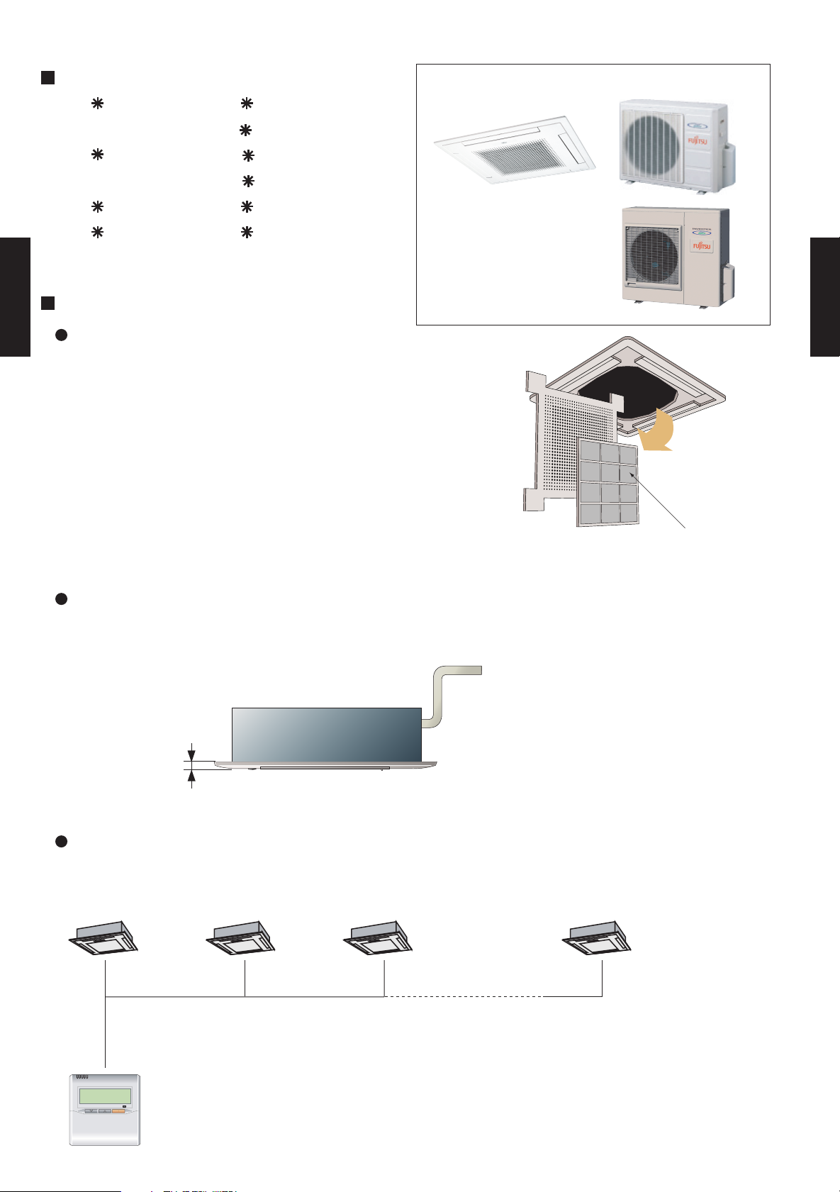
CASSETTE TYPE
AU25-AU30
The control box is easily accessible for maintenance work
Wide opening for easy access.
Detachable,washable filter and intake grille.
Wide opening and long-life filter.
Long-life filter
High efficiency, long-life filter extends the cleaning cycle.
Long-life filter
CASSETTE TYPE
AU25-AU30
Slim intake grille
Slim type intake grille can fit the ceiling after installation.
Easy maintenance
20
(unit: mm)
Group controller
One remote controller can control up to 16 air conditioners.
All of the air conditioners will be operated with the same settings.
Connectable quantity : Maximum 16 indoor units for 1 remote controller.
- (03 - 01) -
Page 3
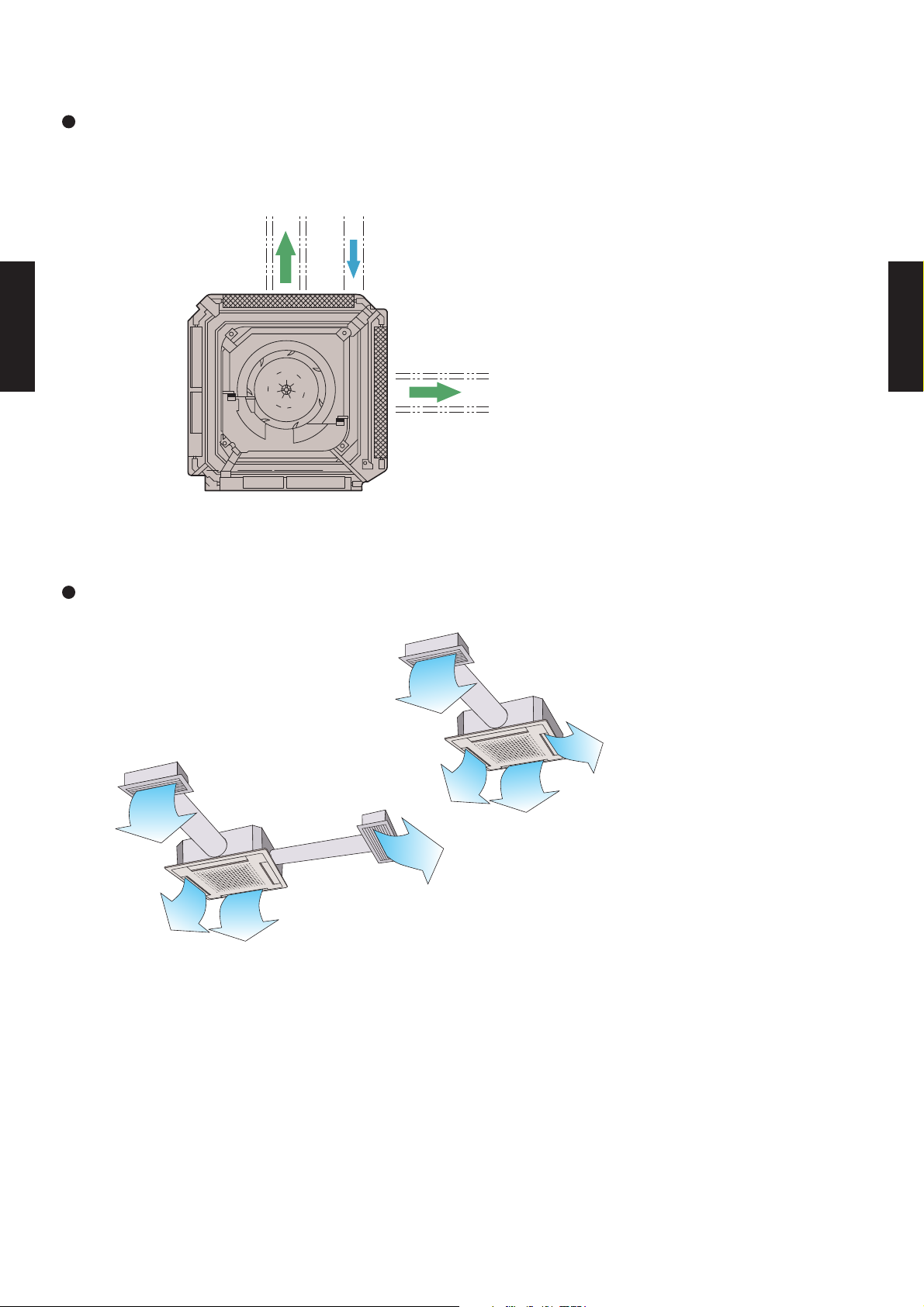
Duct connection hole opening
Fresh air can be introduced through this opening.
Distribution
duct
CASSETTE TYPE
AU25-AU30
Fresh air
CASSETTE TYPE
AU25-AU30
Distribution
duct
Conditioned air can be distributed by means of a distribution duct.
Two-way
One-way
- (03 - 02) -
Page 4
3-2. REMOTE CONTROLLER
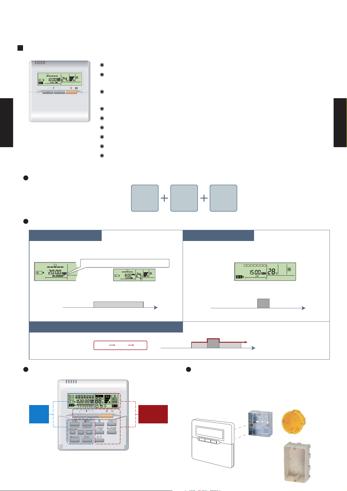
3-2-1. WIRED REMOTE CONTROLLER
FEATURES
Various timer setup (ON / OFF / WEEKLY) are possible.
SUMOTUWETH FR SA
7
3126 9
15 18 21
CASSETTE TYPE
AU25-AU30
High performance and compact size
Equipped with weekly timer as standard function.
(2 times Start / Stop per day for a week)
When setting up a timer, operation mode and a temperature
setup can be changed.
When a failure occurs,the error code is displayed. (Maximum of 16)
Error indication.(A maximum of 16 error histories are memorizable.)
Up to 16 indoor units can be simultaneously controlled.
Anti freeze and energy saving operation are possible.
Easy installation with a slim shape with no boldge in the back.
The room temperature can be controlled by being detected the temperature
accurately with built-in thermo sensor.
CASSETTE TYPE
AU25-AU30
Three functions are combined in
one unit.
Wired
remote
controller
Built-in timers
Possible to set ON/OFF time to operate twice each day
of the week.
SUMOTUWETH FR SA
7
3126 9
15 18 21
Setup screen example
(Set to Wednesday: 8:00 to 20:00.)
0 3 6 9 12 15 18 21 Time
At "Weekly timer" + "Set back timer" setup
Easy-to-understand time bar display
SUMOTUWETH FR SA
7
3126 9
15 18 21
24°C
24°C 28°C 24°C
Weekly
timer
Setback
timer
Setback timerWeekly timer
Possible to set temperature for two time spans and
for each day of the week.
SUMOTUWETH FR SA
Screen
after setup
Setup screen example
(Set from Sunday to Saturday: 12:00 to 15:00, 28 °C.)
0 3 6 9 12 15 18 21 Time
24°C
0 3 6 9 12 15 18 21 Time
28°C
3126 9
15 18 21
28°C
Easy-to-understand operation Simple installation
Components are compatible with standard
switch boxes. Flat back construction allows
equipment to be installed wherever it is
needed.
Timer
area
[
Variable timer control
]
The operation/display sections are zoned according to time and operation, enabling variable programming to match application.
Operation
area
European
switch box
- (03 - 03) -
JIS box
Page 5
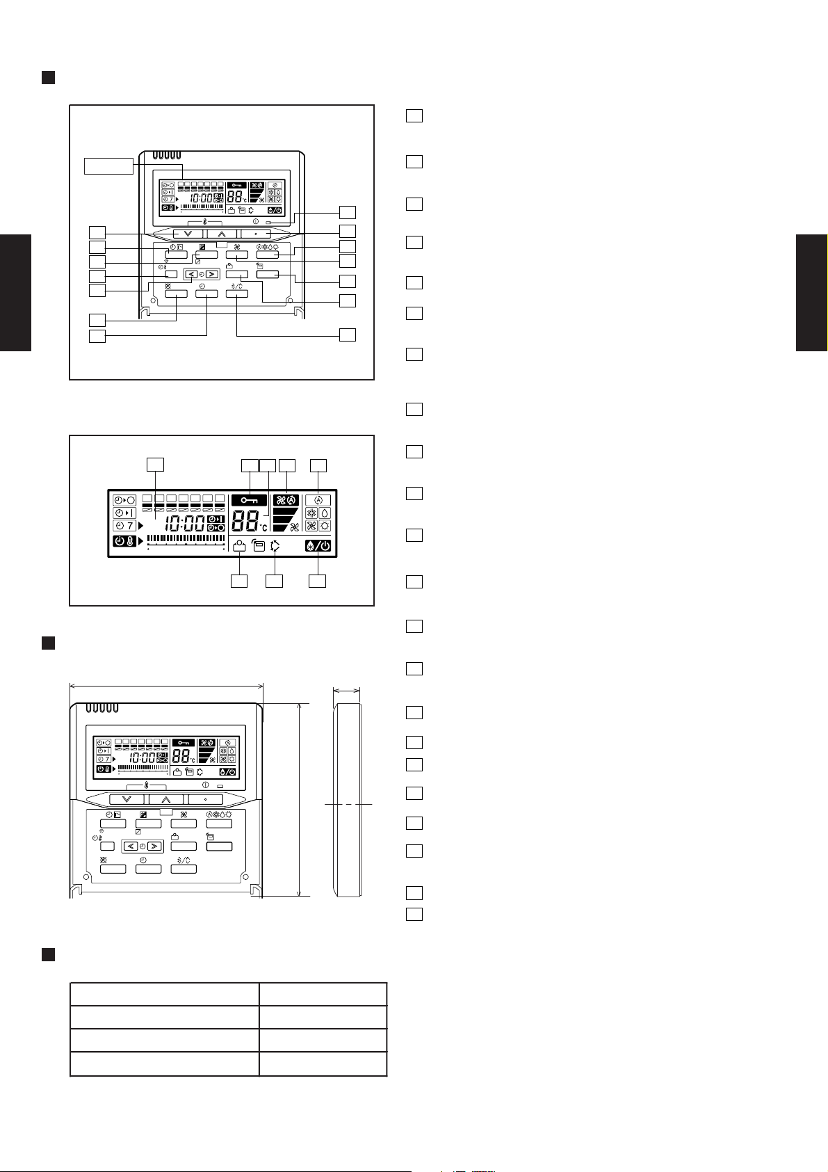
FUNCTIONS
1
START/STOP button
Pressed to start and stop operation.
2
Display
SUMOTUWETH FR
SA
369
12 15 18 21
2
7
8
9
10
11
CASSETTE TYPE
AU25-AU30
12
CLOCK ADJUST
SET BACK
DELETE SET
DAY
DAY OFF
ENERGY
SAVE
THERMO
SENSOR
14
1
3
4
5
6
13
Display panel
15
16
1718 19
Set Temperature button
Selects the setting temperature.
3
Master control button
Selects the operating mode(AUTO, HEAT, FAN, COOL, DRY).
4
Fan control button
Selects the fan speed (AUTO, LOW, MED, HIGH).
5
Thermo sensor button
6
Energy save button
Turns the energy efficient mode on and off.
7
Timer mode (CLOCK ADJUST) button
Selects the timer mode (OFF TIMER, ON TIMER,
WEEKLY TIMER) Set the current time.
8
Day (DAY OFF) button
Temporarily cancels of one day timer.
9
Set back button
pressed select the set back timer.
CASSETTE TYPE
AU25-AU30
SUMOTUWETH FR
369
DIMENSION
120
SUMOTUWETH FR
CLOCK ADJUST
SET BACK
DELETE SET
SA
369
12 15 18 21
DAY
DAY OFF
Front View
12 15 18 21
ENERGY
SAVE
SA
THERMO
SENSOR
202122
[ Unit : mm ]
120
10
Set time button
Pessed to select the set back timer.
11
Delete button
The schedule of a weekly timer is deleted.
12
Set button
Sets the date, hour, minute and on-off time.
13
Vertical air flow direction and swing button
Push for two seconds to change the swing mode
14
17
Operation lamp
Lights during operation and when the timer is on.
15
Timer and clock display
16
Operation mode display
17
Fan speed display
18
Central control display
19
Temperature display
20
Stand by display
Indicates during the oil recovery and defrosting operation.
21
Vertical swing display
22
Energy save display
SPECIFICATION
SIZE (H x W x D mm) 120 x 120 x 17
WEIGHT ( g ) 160
CABLE LENGTH ( m )
POWER ( V )
10
12
- (03 - 04) -
Page 6
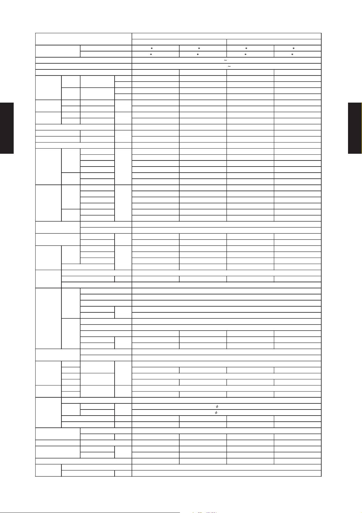
3-3. SPECIFICATIONS
AU 25FUAR AU 30FUAR AU 25UUAR AU 30UUAR
AO 25FNAKL AO 30FNBWL AO 25UNAKL AO 30UNBW L
Rows × Stages
Fin Pitch
Rows × Stages 2 × 30 2 × 38 2 × 30 2 × 38
Fin Pitch 1.45 1.3 1.45 1.3
Aluminium Fin
1.3
ROTARY
198-264V 50Hz
Permanent starting condenser
Copper tube
DRAIN PIPE
MATERIAL
SIZE
246 × 830 × 830
355×1060×1025
34/44 (75/97)
FLARE
9.52(3/8 inc.)
15.88(5/8 inc.)
R410A
MOISTURE REMOVAL
kW/kW
A
FAN MOTOR OUTPUT
m3/h
AIR
CIRCULATION
COOL/HEAT
INDOOR
OUTDOOR
COP
r.p.m
ABS
Aluminium Fin
Outer diameter 37.0 / Inner diameter 32.0
2 × 10
210 × 970 × 26.6
White(5Y9/0.5NN)
Beige(10YR7.5/1.0NN)
Copper tube
dB(A)
NOISE LEVEL
(SOUND
PRESSURE)
COOL/HEAT
FAN SPEED
COOL/HEAT
OUTDOOR
FAN TYPE x Q'ty
INDOOR
OUTDOOR
CASSETTE MODELS
COOLING TYPE
HEAT PUMP TYPE
W
230V 50Hz
Turbo x 1
Propeller x 1
POWER SOURCE
AVAILABLE VOLTAGE RANGE
EUROPEAN ENERGY LABEL
MODEL NAME
INDOOR
OUTDOOR
TYPE
DIMENSIONS
H ×W ×D
INDOOR
TYPE
COOLING
HEATING
CAPACITY
RATED
Fin
Coil
OUTDOOR
Coil
Fin
COMPRESSOR
HEAT
EXCHANGER
TYPE
INDOOR
STARTING METHOD
OUTPUT
mm
mm
REFRIGERANT OIL
CONNECTION METHOD
CASING COLOR
PIPE
SIZEmm WEIGHT
NET
GROSS
NET /
GROSS
REMOTE CONTROLLER TYPE
TYPEmmMAX LENGTH
REFRIGERANT
TYPE
MAX HEIGHT
kg(lbs)
OPERATION(OUTDOOR)
°C
RATED
EER
INPUT POWER
kW
CURRENT
STARTING CURRENT
kW 7.05 8.40 7.00 8.40
BTU/h 24100 28700 23900 28700
kW - - 7.8 9.5
COOLING RATED 2.6 2.95 2.65 2.95
HEATING RATED 2.35 2.78
COOLING RATED 11.5 13.6 11.8 13.6
HEATING RATED 10.5 13.1
COOLING 2.71 2.85 2.64 2.85
HEATING - - 3.32 3.42
CASSETTE TYPE
AU25-AU30
High 1100/- 1250/- 1100/970 1250/1200
Med 940/- 1050/- 940/820 1050/1050
Low 780/- 840/- 780/700 840/840
Quiet - - - -
High 3200/- 3300/- 3200/3200 3300/3300
Low 1600/- 1600/- 1600/1600 1600/1600
High 490/- 560/- 490/440 560/540
Med 430/- 480/- 430/380 480/480
Low 360/- 390/- 360/330 390/390
Quiet - - - -
High 780/- 780/- 780/780 780/780
Low 400/- 400/- 400/400 400/400
INDOOR
OUTDOOR
INDOOR 40 40 40 40
OUTDOOR 65 67 65 67
High 44/- 46/- 44/41 46/46
Med 42/- 44/- 42/37 44/44
Low 39/- 39/- 39/34 39/39
BTU/h 26600 32400
A 60 70 60 70
l/h(pints/h) 2.5(5.3) 3.0(6.3) 2.5(5.3) 3.0(6.3)
D C D C
-
-
-
53/- 53/- 53/54 53/54
-
-
-
CASSETTE TYPE
AU25-AU30
W 1900 2200 1900 2200
Coil Dimensions
Coil Dimensions 630 × 901 × 36.38 798 × 900 × 36.38 630 × 901 ×36.38 798 × 900 × 36.38
INDOOR
INDOOR
OUTDOOR 650 × 830 × 320 830 × 900 × 330 650 × 830 × 320 830 × 900 × 330
INDOOR
OUTDOOR 768 × 984 × 413 970 × 1050 × 445 768 × 984 × 413 970 × 1050 × 445
INDOOR
OUTDOOR 58/62 (128/137) 68/74 (150/163) 59/63 (130/139) 69/75 (152/165)
OUTDOOR
LIQUID
GAS
CHARGE g 1550 2300 2000 2300
COOLING 0 to 43 0 to 43 0 to 43 0 to 43
HEATING -7 to 24 -7 to 24
m 25(Chaegeless:7.5) 30(Chaegeless:7.5) 25(Chaegeless:7.5) 30(Chaegeless:7.5)
m 15 15 15 15
POE POE POE POE
--
WIRED W IRED W IRED W IRED
Note: Specifications are based on the following conditions.
Cooling: Indoor temperature of 27 °CDB / 19 °CWB,and outdoor temperature of 35 °CDB/24 °CWB.
Heating: Indoor temperature of 20 °CDB / 15 °CW B,and outdoor temperature of 7 °CDB/6 °CW B.
Pipe length : 7.5 m, Height difference : 0 m.(Outdoor unit - Indoor unit)
mm
- (03 - 05) -
Page 7
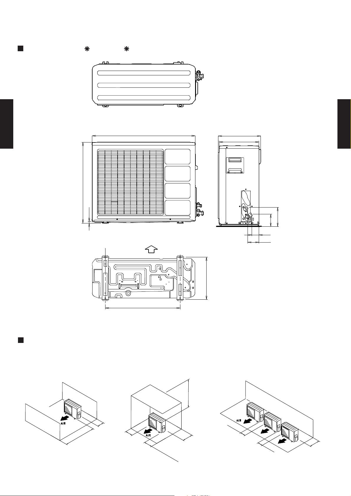
3-4. DIMENSIONS
3-4-1. OUTDOOR UNIT
MODELS : AO 25F, AO 25U
(Unit : mm)
Top view
830
CASSETTE TYPE
AU25-AU30
650
12
Front view
Bottom
Air flow
350
320
Side view
CASSETTE TYPE
AU25-AU30
154
101
58
90
MOUNTING POSITION
When there are obstacles at the
back or front sides.
100 mm
or more
600 mm
or more
Bottom view
100 mm
or more
343
603
When there are obstacles at the
back, side(s), and top.
600 mm or more
300 mm
25
(
S
0 mm o
er
v
i
c
r
more
e s
p
ac
e)
or more
When there are obstacles at the
back, side with the installation of
more than one unit.
250 mm
or more
250 mm
or more
300 mm
or more
- (03 - 06) -
Page 8
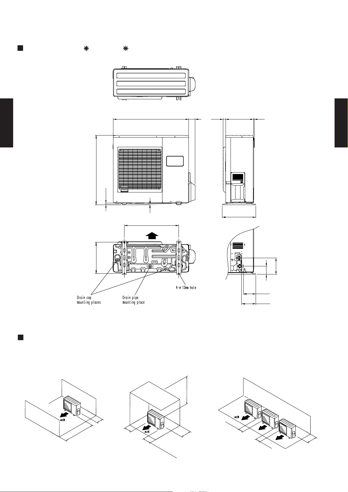
MODELS : AO 30F, AO 30U
Top view
(Unit : mm)
900
CASSETTE TYPE
AU25-AU30
830
21
Front view
370
9
650
Air flow
603
77
31 330
400
12
CASSETTE TYPE
AU25-AU30
Side view
196
99
MOUNTING POSITION
When there are obstacles at the
back or front sides.
100 mm
or more
600 mm
or more
100 mm
or more
Bottom view
When there are obstacles at the
back, side(s), and top.
600 mm or more
300 mm
25
(
S
0 mm o
er
v
i
c
r
more
e s
p
ac
e)
or more
147
170
When there are obstacles at the
back, side with the installation of
more than one unit.
250 mm
or more
250 mm
or more
300 mm
or more
- (03 - 07) -
Page 9
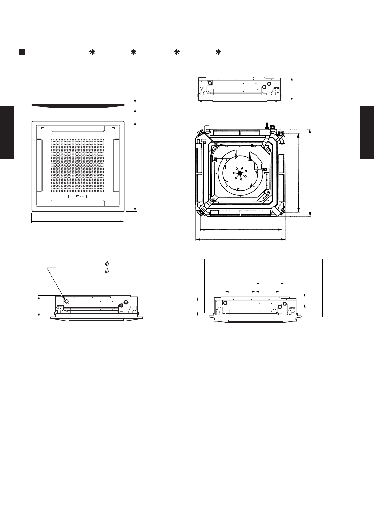
3-4-2. INDOOR UNIT
750
830
750
830
Bottom view
MODELS : AU 25F, AU 25U, AU 30F, AU 30U
CASSETTE TYPE
AU25-AU30
940
(Unit : mm)
246
30
Side view
CASSETTE TYPE
AU25-AU30
940
Bottom view (Panel)
Drain inside Dia. 32
outside Dia. 37
235
Side view (Standard setting)
60
(Drain pipe)
200
305.5
Side view (Slender setting)
298.5
248.5
100
70
(Small pipe)
(Large pipe)
- (03 - 08) -
Page 10
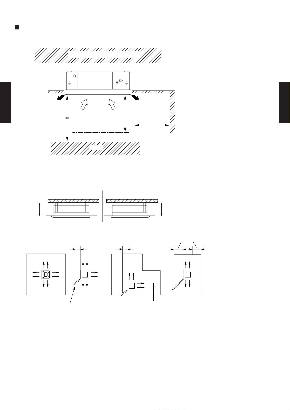
MOUNTING POSITION
Floor
Strong and durable ceiling
CASSETTE TYPE
AU25-AU30
2,300 mm
or more
1,200 mm
or more
1,000 mm
or more
CASSETTE TYPE
AU25-AU30
Obstruction
You can select 2-way setting
(A) Standard setting (B) Slender setting
215 mm
250 mm
or more
100 or more 100 or more
or more
100 or more
(4 directions) (3 directions)
Piping position
(2 directions) (2 directions)
100 or more
- (03 - 09) -
Page 11
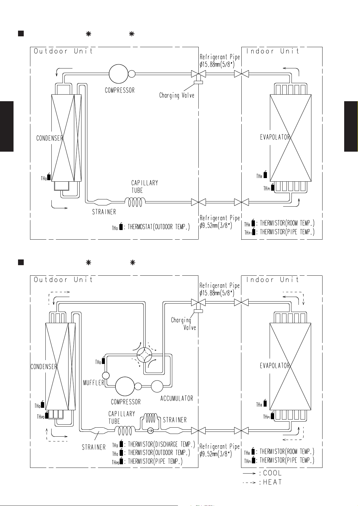
3-5. REFRIGERANT CIRCUIT
MODELS : AU 25F / AO 25F
CASSETTE TYPE
AU25-AU30
CASSETTE TYPE
AU25-AU30
MODELS : AU 25U / AO 25U
4-WAY
VALVE
- (03 - 10) -
Page 12
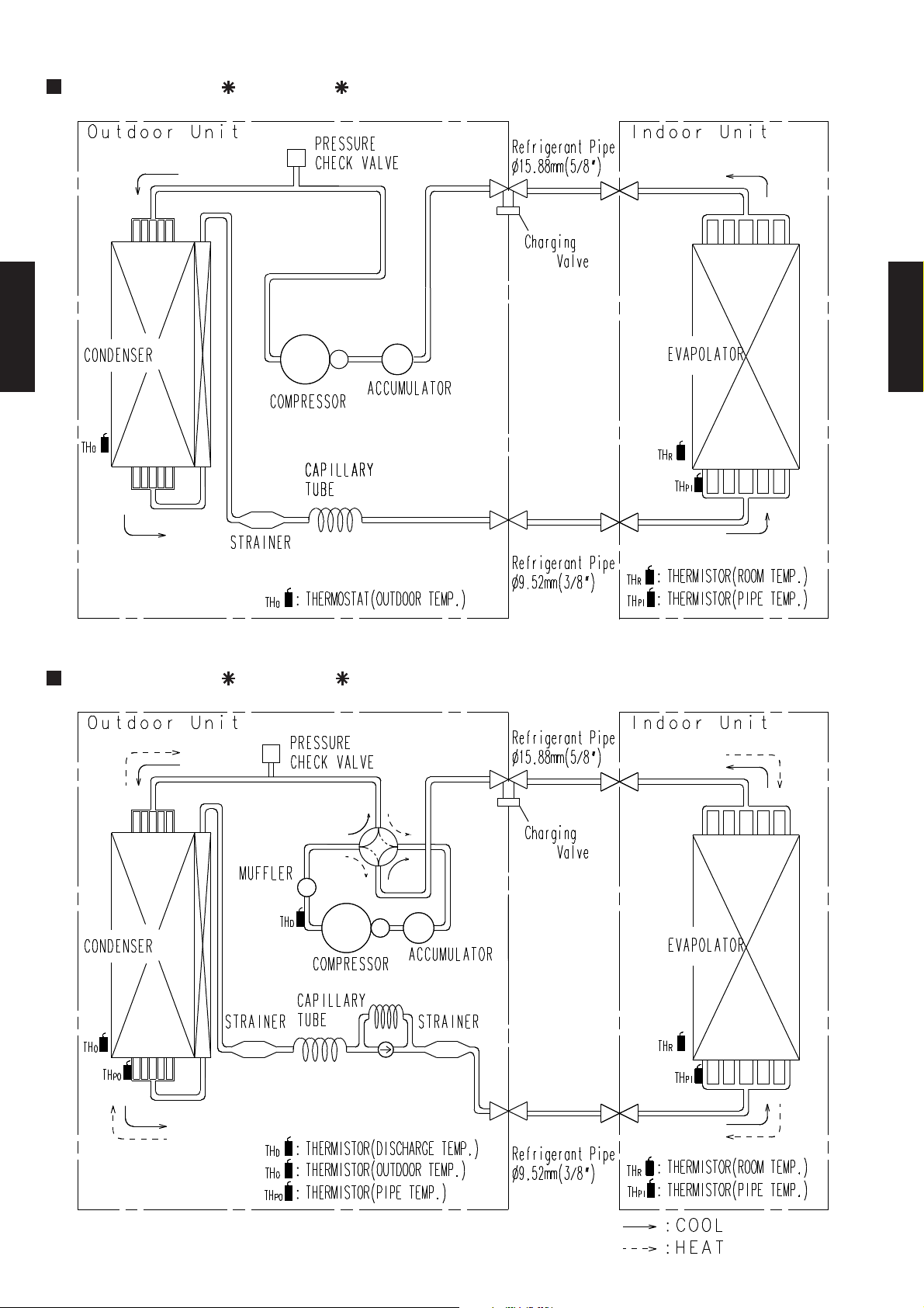
MODELS : AU 30F / AO 30F
CASSETTE TYPE
AU25-AU30
CASSETTE TYPE
AU25-AU30
MODELS : AU 30U / AO 30U
4-WAY
VALVE
- (03 - 11) -
Page 13
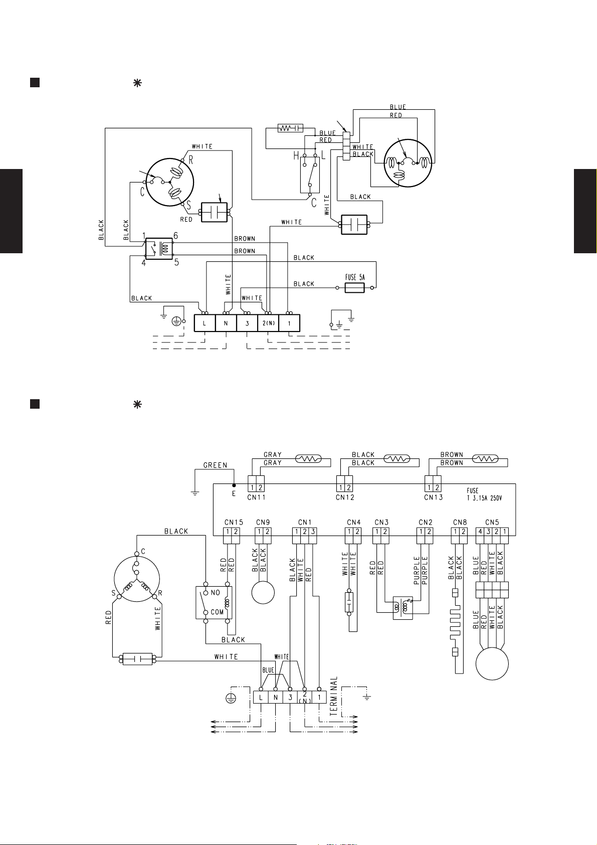
3-6. WIRING DIAGRAMS
3-6-1. OUTDOOR UNIT
MODEL : AO 25F
CR composite
Internal
overload
protector
CASSETTE TYPE
AU25-AU30
Compressor
Compressor
capacitor
Outdoor
thermostat
Connector
Fan motor capacitor
Thermal
protector
Fan motor
CASSETTE TYPE
AU25-AU30
Main relay
TO POWER SUPPLY
TO INDOOR UNIT
MODEL : AO 25U
Compressor
Compressor
capacitor
Main
relay
4WV
Solenoid
coil
Thermistor
(pipe temp.)
Thermistor
(outdoor temp.)
Fan motor
capacitor
Transformer
Belt heater
Thermistor
(discharge temp.)
F M
Fan motor
Controller
PCB
TO POWER SUPPLY
TO INDOOR UNIT
- (03 - 12) -
Page 14

MODEL : AO 30F
BLACK
COMPRESSOR
S R
RED
C
C M
INTERNAL
OVERLOAD
PROTECTOR
RELAY
WHITE
COMPRESSOR
CASSETTE TYPE
AU25-AU30
FUSE
CAPACITOR
WHITE
WHITE
WHITE
BLACK
GRAY
1NL 2 3
1 5
4 6
BROWN
BLACK
PURPLE
C
OUTDOOR
THERMOSTAT
BROWN
TERMINAL
H
L
FAN MOTOR
CAPACITOR
BLUE
RED
WHITE
BLACK
1364
1364
THERMAL
PROTECTOR
FAN MOTOR
F M
CASSETTE TYPE
AU25-AU30
TO INDOOR
TO POWER SUPPLY
UNIT
MODEL : AO 30U
BLACK
INTERNAL
COMPRESSOR
COMPRESSOR
CAPACITOR
BLACK
FUSE
C
C M
S R
RED
GRAY
OVERLOAD
PROTECTOR
WHITE
WHITE
WHITE
1NL 2 3
THERMAL
PROTECTOR
1 5
4 6
RED
BLACK
FAN MOTOR
RELAY
TERMINAL
F M
FAN MOTOR
CAPACITOR
RED
RED
WHITE
BLACK
1364
BLUE
1364
RED
WHITE
BLACK
YELLOW
YELLOW
GRAY
GRAY
21
21
4321
7531
21
21
GRAY
BLACK
21
21
BLACK
BROWN
21
21
BROWN
BLACK
13
21
BLACK
THERMISTOR
(PIPE TEMP.)
THERMISTOR
(OUTDOOR TEMP.)
THERMISTOR
(DISCHARGE TEMP.)
4WV
SOLENOID COIL
BLACK
13
21
21
21
3
51
21
3
BLACK
RED
21
21
RED
21
21
BELT HEATER
PRINTED CIRCUIT BOARD
PURPLE
31
21
PURPLE
TRANSFORMER
TO POWER SUPPLY
TO INDOOR
UNIT
FUSE
- (03 - 13) -
Page 15

3-6-2. INDOOR UNIT
MODEL : AU 25F
TO REMOTE
CONTROL UNIT
Terminal
Thermistor
(pipe temp.)
Thermistor
(room temp.)
Stepping
motor
CASSETTE TYPE
AU25-AU30
Filter board
Controller
PCB
Drain pump
M
motor
CASSETTE TYPE
AU25-AU30
Fan motor
FM
Fan motor
TO OUTDOOR UNIT
Terminal
capacitor
MODEL : AU 25U
Thermistor
(pipe temp.)
TO REMOTE
CONTROL UNIT
Thermistor
(room temp.)
Terminal
TO OUTDOOR UNIT
Filter board
Controller
PCB
Terminal
Fan motor
FM
- (03 - 14) -
Stepping
motor
Float switch
Drain pump
M
motor
Fan motor
capacitor
Page 16

MODEL : AU 30F
CASSETTE TYPE
AU25-AU30
CASSETTE TYPE
AU25-AU30
MODEL : AU 30U
- (03 - 15) -
Page 17

3-7. CAPACITY TABLE
(°CDB)
Outdoor temperature
18 °CDB
12 °CWB
15 °CWB
32 °CDB
23 °CWB
22 °CWB
16 °CWB
18 °CWB
19 °CWB
21 °CWB
30 °CDB
21 °CDB
23 °CDB
26 °CDB
27 °CDB
29 °CDB
Indoor temperature
MODELS : AU 25F / AO 25F
COOLING
AFR 18.3
TC SHC PI TC SHC PI TC SHC PI TC SHC PI TC SHC PI TC SHC PI TC SHC PI TC SHC PI
0 8.05 6.02 1.63 8.21 6.05 1.67 8.37 6.07 1.69 8.61 6.33 1.71 8.71 6.28 1.72 8.89 6.17 1.74 8.98 6.11 1.75 9.06 6.36 1.76
5 7.76 5.86 1.83 7.94 5.89 1.87 8.13 5.91 1.89 8.42 6.21 1.92 8.54 6.18 1.93 8.75 6.09 1.96 8.84 6.04 1.97 8.93 6.30 1.99
10 7.43 5.66 2.02 7.62 5.68 2.06 7.80 5.72 2.09 8.12 6.05 2.13 8.24 6.02 2.14 8.46 5.95 2.18 8.56 5.91 2.19 8.66 6.18 2.21
15 7.08 5.46 2.21 7.25 5.49 2.26 7.44 5.53 2.29 7.73 5.86 2.33 7.86 5.84 2.35 8.08 5.78 2.39 8.18 5.75 2.41 8.28 6.02 2.43
20 7.06 5.28 2.43 7.21 5.30 2.47 7.38 5.33 2.49 7.67 5.65 2.54 7.79 5.63 2.56 8.02 5.58 2.61 8.12 5.56 2.63 8.22 5.84 2.65
25 7.34 5.44 2.10 7.52 5.46 2.13 7.69 5.50 2.14 7.98 5.80 2.17 8.10 5.78 2.19 8.32 5.72 2.22 8.42 5.68 2.23 8.52 5.96 2.24
30 6.87 5.19 2.31 7.07 5.22 2.32 7.23 5.28 2.34 7.50 5.59 2.38 7.62 5.57 2.39 7.84 5.52 2.43 7.95 5.50 2.44 8.05 5.78 2.45
35 6.39 4.97 2.51 6.51 5.01 2.52 6.68 5.04 2.54 6.93 5.34 2.58 7.05 5.33 2.60 7.28 5.30 2.63 7.38 5.28 2.65 7.49 5.57 2.67
CASSETTE TYPE
AU25-AU30
40 5.82 4.72 2.73 5.90 4.74 2.73 6.04 4.76 2.75 6.29 5.07 2.79 6.41 5.07 2.81 6.63 5.04 2.85 6.74 5.03 2.87 6.84 5.33 2.91
43 5.41 4.51 2.85 5.50 4.56 2.86 5.63 4.58 2.88 5.87 4.90 2.92 5.99 4.89 2.94 6.21 4.88 2.98 6.33 4.88 3.00 6.45 5.19 3.02
AFR: Air flow rate (m3/min)
TC : Total capacity (kW)
SHC: Sensible Heat capacity (kW)
PI : Power Input (kW)
CASSETTE TYPE
AU25-AU30
- (03 - 16) -
Page 18

MODELS : AU 25U / AO 25U
(°CDB)
Outdoor temperature
18 °CDB
12 °CWB
21 °CWB
16 °CWB
22 °CWB
23 °CDB
21 °CDB
15 °CWB
29 °CDB
Indoor temperature
32 °CDB
23 °CWB
27 °CDB
30 °CDB
18 °CWB
19 °CWB
26 °CDB
( °CDB)
( °CWB)
16 °CDB
18 °CDB
20 °CDB
Indoor temperature
Outdoor temperature
27 °CDB
30 °CDB
25 °CDB
23 °CDB
COOLING
AFR 18.3
TC SHC PI TC SHC PI TC SHC PI TC SHC PI TC SHC PI TC SHC PI TC SHC PI TC SHC PI
0 7.99 5.97 1.66 8.15 5.99 1.71 8.31 6.02 1.72 8.55 6.27 1.74 8.65 6.22 1.76 8.83 6.11 1.78 8.91 6.05 1.79 8.99 6.30 1.80
5 7.71 5.81 1.87 7.88 5.83 1.90 8.08 5.85 1.92 8.36 6.15 1.96 8.48 6.12 1.97 8.68 6.03 2.00 8.78 5.98 2.01 8.87 6.24 2.02
10 7.38 5.61 2.05 7.56 5.62 2.10 7.74 5.67 2.13 8.06 5.99 2.17 8.18 5.97 2.19 8.40 5.90 2.22 8.50 5.86 2.24 8.60 6.12 2.25
15 7.03 5.41 2.26 7.20 5.44 2.30 7.38 5.48 2.33 7.68 5.80 2.38 7.80 5.78 2.40 8.02 5.73 2.44 8.12 5.70 2.46 8.22 5.97 2.48
20 7.01 5.23 2.47 7.16 5.25 2.51 7.33 5.28 2.54 7.61 5.60 2.59 7.73 5.58 2.61 7.96 5.53 2.66 8.06 5.50 2.68 8.16 5.78 2.70
25 7.28 5.39 2.14 7.47 5.41 2.17 7.64 5.44 2.18 7.92 5.75 2.22 8.04 5.73 2.23 8.26 5.66 2.26 8.36 5.63 2.27 8.45 5.90 2.29
30 6.82 5.14 2.35 7.02 5.17 2.37 7.18 5.23 2.39 7.45 5.54 2.42 7.57 5.52 2.44 7.79 5.47 2.47 7.89 5.45 2.49 8.00 5.73 2.50
35 6.35 4.93 2.56 6.46 4.96 2.57 6.63 4.99 2.59 6.88 5.29 2.63 7.00 5.28 2.65 7.22 5.25 2.69 7.33 5.23 2.70 7.44 5.52 2.72
CASSETTE TYPE
AU25-AU30
40 5.77 4.67 2.78 5.86 4.70 2.79 6.00 4.72 2.80 6.24 5.02 2.85 6.36 5.02 2.87 6.58 4.99 2.91 6.69 4.98 2.93 6.80 5.28 2.97
43 5.37 4.46 2.90 5.46 4.51 2.91 5.59 4.54 2.93 5.83 4.85 2.97 5.95 4.85 2.99 6.17 4.84 3.04 6.29 4.83 3.06 6.40 5.14 3.08
HEATING
AFR 18.3
CASSETTE TYPE
AU25-AU30
-7 -9 5.07 1.78 4.99 1.83 4.84 1.89 4.68 1.95 4.60 1.97 4.45 2.03 4.29 2.06
-4 -6 5.54 1.92 5.46 1.97 5.30 2.03 5.15 2.09 5.07 2.12 4.91 2.17 4.76 2.20
1 -1 6.24 2.17 6.16 2.23 6.01 2.28 5.85 2.34 5.77 2.37 5.62 2.43 5.46 2.45
5 3 7.64 2.23 7.57 2.28 7.41 2.33 7.25 2.37 7.18 2.40 7.02 2.44 6.86 2.47
7 6 8.03 2.26 7.96 2.30 7.80 2.35 7.64 2.40 7.57 2.42 7.41 2.47 7.25 2.49
12 10 8.58 2.42 8.50 2.47 8.35 2.51 8.19 2.56 8.11 2.59 7.96 2.63 7.80 2.66
15 13 8.66 2.51 8.58 2.56 8.42 2.61 8.27 2.66 8.19 2.68 8.03 2.73 7.88 2.75
20 15 8.03 2.26 7.96 2.30 7.80 2.35 7.64 2.40 7.57 2.42 7.41 2.47 7.25 2.49
24 17 7.57 2.12 7.49 2.16 7.33 2.21 7.18 2.26 7.10 2.28 6.94 2.33 6.79 2.35
AFR: Air flow rate (m3/min)
TC : Total capacity (kW)
SHC: Sensible Heat capacity (kW)
PI : Power Input (kW)
TC PI TC PI TC PI TC PI TC PI TC PI TC PI
- (03 - 17) -
Page 19

MODELS : AU 30F / AO 30F
(°CDB)
30 °CDB
21 °CDB
23 °CDB
26 °CDB
27 °CDB
29 °CDB
23 °CWB
22 °CWB
16 °CWB
18 °CWB
19 °CWB
21 °CWB
Outdoor temperature
18 °CDB
12 °CWB
Indoor temperature
15 °CWB
32 °CDB
COOLING
AFR 20.8
TC SHC PI TC SHC PI TC SHC PI TC SHC PI TC SHC PI TC SHC PI TC SHC PI TC SHC PI
0 9.59 7.16 1.85 9.78 7.19 1.90 9.97 7.22 1.91 10.25 7.52 1.94 10.38 7.46 1.95 10.60 7.33 1.98 10.70 7.26 1.99 10.79 7.56 2.00
5 9.25 6.97 2.08 9.46 7.00 2.12 9.69 7.02 2.14 10.03 7.38 2.18 10.17 7.34 2.19 10.42 7.24 2.23 10.53 7.18 2.24 10.64 7.49 2.25
10 8.85 6.73 2.29 9.07 6.75 2.34 9.29 6.80 2.37 9.67 7.19 2.41 9.82 7.16 2.43 10.08 7.08 2.47 10.20 7.03 2.49 10.32 7.35 2.51
15 8.44 6.49 2.51 8.64 6.53 2.57 8.86 6.57 2.60 9.21 6.96 2.65 9.36 6.94 2.67 9.63 6.87 2.72 9.75 6.83 2.74 9.86 7.16 2.76
20 8.41 6.27 2.75 8.59 6.30 2.80 8.80 6.34 2.83 9.13 6.72 2.88 9.28 6.70 2.91 9.55 6.64 2.96 9.68 6.60 2.98 9.80 6.94 3.00
25 8.74 6.47 2.39 8.96 6.50 2.41 9.16 6.53 2.43 9.50 6.90 2.47 9.65 6.87 2.48 9.91 6.80 2.52 10.03 6.76 2.53 10.15 7.08 2.54
30 8.19 6.17 2.62 8.42 6.21 2.64 8.61 6.28 2.66 8.93 6.64 2.70 9.08 6.62 2.71 9.34 6.56 2.75 9.47 6.53 2.77 9.59 6.87 2.79
35 7.61 5.91 2.85 7.76 5.96 2.86 7.96 5.99 2.89 8.26 6.35 2.93 8.40 6.34 2.95 8.67 6.30 2.99 8.80 6.27 3.01 8.93 6.62 3.03
CASSETTE TYPE
AU25-AU30
40 6.93 5.61 3.09 7.03 5.64 3.10 7.20 5.66 3.12 7.49 6.03 3.17 7.63 6.02 3.19 7.89 5.99 3.24 8.03 5.98 3.26 8.15 6.34 3.30
43 6.44 5.36 3.23 6.55 5.42 3.24 6.70 5.44 3.26 6.99 5.82 3.31 7.14 5.82 3.33 7.40 5.80 3.38 7.55 5.80 3.40 7.68 6.16 3.43
AFR: Air flow rate (m3/min)
TC : Total capacity (kW)
SHC: Sensible Heat capacity (kW)
PI : Power Input (kW)
CASSETTE TYPE
AU25-AU30
- (03 - 18) -
Page 20

MODELS : AU 30U / AO 30U
(°CDB)
29 °CDB
Indoor temperature
32 °CDB
23 °CWB
27 °CDB
30 °CDB
18 °CWB
19 °CWB
26 °CDB
23 °CDB
21 °CDB
15 °CWB
21 °CWB
16 °CWB
22 °CWB
Outdoor temperature
18 °CDB
12 °CWB
(°CDB)
(°CWB)
Outdoor temperature
16 °CDB
18 °CDB
20 °CDB
Indoor temperature
27 °CDB
30 °CDB
25 °CDB
23 °CDB
COOLING
AFR 20.8
TC SHC PI TC SHC PI TC SHC PI TC SHC PI TC SHC PI TC SHC PI TC SHC PI TC SHC PI
0 9.59 7.16 1.85 9.78 7.19 1.90 9.97 7.22 1.91 10.25 7.52 1.94 10.38 7.46 1.95 10.60 7.33 1.98 10.70 7.26 1.99 10.79 7.56 2.00
5 9.25 6.97 2.08 9.46 7.00 2.12 9.69 7.02 2.14 10.03 7.38 2.18 10.17 7.34 2.19 10.42 7.24 2.23 10.53 7.18 2.24 10.64 7.49 2.25
10 8.85 6.73 2.29 9.07 6.75 2.34 9.29 6.80 2.37 9.67 7.19 2.41 9.82 7.16 2.43 10.08 7.08 2.47 10.20 7.03 2.49 10.32 7.35 2.51
15 8.44 6.49 2.51 8.64 6.53 2.57 8.86 6.57 2.60 9.21 6.96 2.65 9.36 6.94 2.67 9.63 6.87 2.72 9.75 6.83 2.74 9.86 7.16 2.76
20 8.41 6.27 2.75 8.59 6.30 2.80 8.80 6.34 2.83 9.13 6.72 2.88 9.28 6.70 2.91 9.55 6.64 2.96 9.68 6.60 2.98 9.80 6.94 3.00
25 8.74 6.47 2.39 8.96 6.50 2.41 9.16 6.53 2.43 9.50 6.90 2.47 9.65 6.87 2.48 9.91 6.80 2.52 10.03 6.76 2.53 10.15 7.08 2.54
30 8.19 6.17 2.62 8.42 6.21 2.64 8.61 6.28 2.66 8.93 6.64 2.70 9.08 6.62 2.71 9.34 6.56 2.75 9.47 6.53 2.77 9.59 6.87 2.79
35 7.61 5.91 2.85 7.76 5.96 2.86 7.96 5.99 2.89 8.26 6.35 2.93 8.40 6.34 2.95 8.67 6.30 2.99 8.80 6.27 3.01 8.93 6.62 3.03
CASSETTE TYPE
AU25-AU30
40 6.93 5.61 3.09 7.03 5.64 3.10 7.20 5.66 3.12 7.49 6.03 3.17 7.63 6.02 3.19 7.89 5.99 3.24 8.03 5.98 3.26 8.15 6.34 3.30
43 6.44 5.36 3.23 6.55 5.42 3.24 6.70 5.44 3.26 6.99 5.82 3.31 7.14 5.82 3.33 7.40 5.80 3.38 7.55 5.80 3.40 7.68 6.16 3.43
HEATING
AFR 20.8
CASSETTE TYPE
AU25-AU30
-7 -9 6.18 2.10 6.08 2.17 5.89 2.24 5.70 2.30 5.61 2.34 5.42 2.40 5.23 2.44
-4 -6 6.75 2.27 6.65 2.34 6.46 2.40 6.27 2.47 6.18 2.50 5.99 2.57 5.80 2.60
1 -1 7.60 2.57 7.51 2.64 7.32 2.70 7.13 2.77 7.03 2.80 6.84 2.87 6.65 2.90
5 3 9.31 2.64 9.22 2.69 9.03 2.75 8.84 2.81 8.74 2.84 8.55 2.89 8.36 2.92
7 6 9.79 2.67 9.69 2.72 9.50 2.78 9.31 2.84 9.22 2.86 9.03 2.92 8.84 2.95
12 10 10.45 2.86 10.36 2.92 10.17 2.97 9.98 3.03 9.88 3.06 9.69 3.11 9.50 3.14
15 13 10.55 2.97 10.45 3.03 10.26 3.09 10.07 3.14 9.98 3.17 9.79 3.22 9.60 3.25
20 15 9.79 2.67 9.69 2.72 9.50 2.78 9.31 2.84 9.22 2.86 9.03 2.92 8.84 2.95
24 17 9.22 2.50 9.12 2.56 8.93 2.61 8.74 2.67 8.65 2.70 8.46 2.75 8.27 2.78
AFR: Air flow rate (m3/min)
TC : Total capacity (kW)
SHC: Sensible Heat capacity (kW)
PI : Power Input (kW)
TC PI TC PI TC PI TC PI TC PI TC PI TC PI
- (03 - 19) -
Page 21

3-8. CAPACITY COMPENSATION FOR PIPE LENGTH
Outdoor unit
is up-side
COOLING
HEIGHT DIFFERENCE (m)
HEIGHT DIFFERENCE (m)
HEATING
Outdoor unit
is up-side
Outdoor unit
is bottom-side
PIPE LENGTH (m)
PIPE LENGTH (m)
Outdoor unit
is bottom-side
PIPE LENGTH (m)
COOLING
HEIGHT DIFFERENCE (m)
Outdoor unit
is up-side
Outdoor unit
is bottom-side
AND HEIGHT DIFFERENCE
MODELS : AU 25F / AO 25F
5 7.5 10 15 20 25
15 - - - 0.952 0.919 0.888
10 - - 0.985 0.952 0.919 0.888
7.5 - 1.000 0.985 0.952 0.919 0.888
5 1.010 1.000 0.985 0.952 0.919 0.888
0 1.010 1.000 0.985 0.952 0.919 0.888
CASSETTE TYPE
AU25-AU30
-5 1.002 0.992 0.977 0.944 0.912 0.881
CASSETTE TYPE
AU25-AU30
-7.5 - 0.988 0.973 0.941 0.908 0.877
-10 - - 0.969 0.937 0.904 0.874
-15 - - - 0.929 0.897 0.867
MODELS : AU 25U / AO 25U
5 7.5 10 15 20 25
15 - - - 0.952 0.919 0.888
10 - - 0.985 0.952 0.919 0.888
7.5 - 1.000 0.985 0.952 0.919 0.888
5 1.010 1.000 0.985 0.952 0.919 0.888
0 1.010 1.000 0.985 0.952 0.919 0.888
-5 1.002 0.992 0.977 0.944 0.912 0.881
-7.5 - 0.988 0.973 0.941 0.908 0.877
-10 - - 0.969 0.937 0.904 0.874
-15 - - - 0.929 0.897 0.867
15 - - - 0.956 0.939 0.922
10 - - 0.979 0.961 0.943 0.927
7.5 - 0.993 0.982 0.964 0.946 0.929
5 1.005 0.995 0.984 0.966 0.948 0.931
0 1.010 1.000 0.989 0.971 0.953 0.936
-5 1.010 1.000 0.989 0.971 0.953 0.936
-7.5 - 1.000 0.989 0.971 0.953 0.936
-10 - - 0.989 0.971 0.953 0.936
-15 - - - 0.971 0.953 0.936
5 7.5 10 15 20 25
- (03 - 20) -
Page 22

MODELS : AU 30F / AO 30F
COOLING
PIPE LENGTH (m)
HEIGHT DIFFERENCE (m)
Outdoor unit
is bottom-side
Outdoor unit
is up-side
PIPE LENGTH (m)
COOLING
HEIGHT DIFFERENCE (m)
Outdoor unit
is up-side
Outdoor unit
is bottom-side
Outdoor unit is
bottom-side
Outdoor unit
is up-side
HEIGHT DIFFERENCE (m)
PIPE LENGTH (m)
HEATING
5 7.5 10 15 20 25 30
15 - - - 0.952 0.919 0.888 0.857
10 - - 0.985 0.952 0.919 0.888 0.857
7.5 - 1.000 0.985 0.952 0.919 0.888 0.857
5 1.010 1.000 0.985 0.952 0.919 0.888 0.857
0 1.010 1.000 0.985 0.952 0.919 0.888 0.857
-5 1.002 0.992 0.977 0.944 0.912 0.881 0.850
CASSETTE TYPE
AU25-AU30
-7.5 - 0.988 0.973 0.941 0.908 0.877 0.847
CASSETTE TYPE
AU25-AU30
-10 - - 0.969 0.937 0.904 0.874 0.843
-15 - - - 0.929 0.897 0.867 0.836
MODELS : AU 30U / AO 30U
5 7.5 10 15 20 25 30
15 - - - 0.952 0.919 0.888 0.857
10 - - 0.985 0.952 0.919 0.888 0.857
7.5 - 1.000 0.985 0.952 0.919 0.888 0.857
5 1.010 1.000 0.985 0.952 0.919 0.888 0.857
0 1.010 1.000 0.985 0.952 0.919 0.888 0.857
-5 1.002 0.992 0.977 0.944 0.912 0.881 0.850
-7.5 - 0.988 0.973 0.941 0.908 0.877 0.847
-10 - - 0.969 0.937 0.904 0.874 0.843
-15 - - - 0.929 0.897 0.867 0.836
15 - - - 0.956 0.939 0.922 0.904
10 - - 0.979 0.961 0.943 0.927 0.909
7.5 - 0.993 0.982 0.964 0.946 0.929 0.911
5 1.005 0.995 0.984 0.966 0.948 0.931 0.913
0 1.010 1.000 0.989 0.971 0.953 0.936 0.918
-5 1.010 1.000 0.989 0.971 0.953 0.936 0.918
-7.5 - 1.000 0.989 0.971 0.953 0.936 0.918
-10 - - 0.989 0.971 0.953 0.936 0.918
-15 - - - 0.971 0.953 0.936 0.918
5 7.5 10 15 20 25 30
- (03 - 21) -
Page 23

3-9. ADDITIONAL CHARGE CALCULATION
R410A
1550
PIPE LENGTH m
7.5 10 15 20 25(MAX)
ADDITIONAL CHARGE g
0 (Charge less)
+50 +150 +250 +350
20g/m
R410A
2000
7.5 10 15 20 25(MAX)
0 (Charge less)
40g/m
R410A
2300
7.5 10 15 20 25 30 (MAX)
0 (Charge less)
20g/m
R410A
2300
7.5 10 15 20 25 30 (MAX)
0 (Charge less)
40g/m
MODELS : AU 25F / AO 25F
REFRIGERANT TYPE
REFRIGERANT AMOUNT g
REFRIGERANT CHARGE
CASSETTE TYPE
AU25-AU30
MODELS : AU 25U / AO 25U
REFRIGERANT TYPE
REFRIGERANT AMOUNT g
CASSETTE TYPE
AU25-AU30
REFRIGERANT CHARGE
PIPE LENGTH m
ADDITIONAL CHARGE g
MODELS : AU 30F / AO 30F
REFRIGERANT TYPE
REFRIGERANT AMOUNT g
REFRIGERANT CHARGE
PIPE LENGTH m
ADDITIONAL CHARGE g
MODELS : AU 30U / AO 30U
REFRIGERANT TYPE
REFRIGERANT AMOUNT g
+100 +300 +500 +700
+50 +150 +250 +350 +450
REFRIGERANT CHARGE
PIPE LENGTH m
ADDITIONAL CHARGE g
+100 +300 +500 +700 +900
- (03 - 22) -
Page 24

3-10. OPERATION RANGE
Cooling
Dry
Heating 16 to 30°C - -7 to 24°C
Model
AO 25U
AO 30U
AU 25U
AU 30U
Operation Range
Indoor unit Outdoor unit Mode Indoor unit Indoor humidity Outdoor unit
Model
AO 25F
AO 30F
AU 25F
AU 30F
Operation Range
Cooling
Dry
18 to 32°C
About 80% or less
0 to 43°C
Indoor unit Outdoor unit Mode Indoor unit Indoor humidity Outdoor unit
CASSETTE TYPE
AU25-AU30
18 to 32°C About 80% or less 0 to 43°C
CASSETTE TYPE
AU25-AU30
- (03 - 23) -
Page 25

3-11. FAN PERFORMANCE AND AIR FLOW
3-11-1. AIR VELOCITY DISTRIBUTION
MODELS : AU 25F, AU 25U
4-WAY AIR OUTLET
(m)
3
2
1
0.5
1
2
0.25
UNIT : m/s
Note :
Condition
Fan speed : High
Operation mode :FAN
0
0.25 2 1 0.5 0.25
210.5
1
CASSETTE TYPE
AU25-AU30
2
3
8765432
(m)
2
2
1
1
0.5
UNIT : m/s
2
1
0.5
0.25
(m)
0
2
1
0
0.25
87
654321012345678
2
1
0.5
0.25
21012
2
1
0.25
0.5
1012345678
UNIT : m/s
2
1
0.5
0.25
SIDE VIEW
HORIZONTAL LOUVER
: Downward
(m)
TOP VIEW
HORIZONTAL LOUVER
: Upward
(m)
SIDE VIEW
HORIZONTAL LOUVER
: Upward
(m)
CASSETTE TYPE
AU25-AU30
2-WAY AIR OUTLET
(m)
1
0
1
87654321012345678
(m)
2
1
0
87654321012345678
0.25
0.5
210.50.25 2 1 0.5 0.25
2
1
2
1
0.5
- (03 - 24) -
0.25
UNIT : m/s
TOP VIEW
HORIZONTAL LOUVER
: Upward
(m)
UNIT : m/s
SIDE VIEW
HORIZONTAL LOUVER
: Upward
(m)
Page 26

MODELS : AU 30F, AU 30U
4-WAY AIR OUTLET
(m)
3
2
1
0.5
1
2
0.25
UNIT : m/s
Note :
Condition
Fan speed : High
Operation mode :FAN
0
0.25
211 0.50.5 0.25
2
1
CASSETTE TYPE
AU25-AU30
2
3
8765432
(m)
2
2
1
1
0.5
UNIT : m/s
(m)
0
2
1
0
0.25
87
654321012345678
22
11
0.5 0.5
0.25 0.25
21012
2
1
0.25
0.5
1012345678
UNIT : m/s
2
1
0.5
SIDE VIEW
HORIZONTAL LOUVER
: Downward
(m)
0.25
TOP VIEW
HORIZONTAL LOUVER
: Upward
(m)
SIDE VIEW
HORIZONTAL LOUVER
: Upward
(m)
CASSETTE TYPE
AU25-AU30
2-WAY AIR OUTLET
(m)
1
0
1
87654321012345678
(m)
2
1
0
0.25
87654321012345678
0.5
1
UNIT : m/s
210.50.25 2 1 0.5 0.25
UNIT : m/s
2
2
- (03 - 25) -
1
0.5
0.25
TOP VIEW
HORIZONTAL LOUVER
: Upward
(m)
SIDE VIEW
HORIZONTAL LOUVER
: Upward
(m)
Page 27

3-11-2. AIR FLOW
m3/h
1100
m3/h
940
m3/h
780
m3/h
3200
m3/h
1600
Indoor unit
Outdoor unit
FAN SPEED
AIR FLOW
NUMBER OF
ROTATIONS
(r.p.m)
MODELS : AU 25F / AO 25F, AU 25U / AO 25U
HIGH 490 l/s 306
CFM 647
CASSETTE TYPE
AU25-AU30
MED 430 l/s 261
CASSETTE TYPE
AU25-AU30
CFM 553
LOW 360 l/s 217
CFM 459
HIGH 780 l/s 889
CFM 1883
LOW 400 l/s 444
CFM 942
- (03 - 26) -
Page 28

MODELS : AU 30F / AO 30F, AU 30U / AO 30U
m3/h
1250
m3/h
1050
m3/h
840
m3/h
3300
m3/h
1600
Indoor unit
Outdoor unit
NUMBER OF
FAN SPEED AIR FLOW
HIGH 560 l/s 347
ROTATIONS
(r.p.m)
CFM 736
CASSETTE TYPE
AU25-AU30
MED 480 l/s 292
CASSETTE TYPE
AU25-AU30
CFM 618
LOW 390 l/s 233
CFM 494
HIGH 780 l/s 917
CFM 1942
LOW 400 l/s 444
CFM 942
- (03 - 27) -
Page 29

3-11-3. DUCT CONNECTION
MODELS : AU 25F, AU 25U, AU 30F, AU 30U
OUTLET AIR
(Pa)
98
L=5m
Duct
(Inside Dia. ø100mm)
DUCT
L
CASSETTE TYPE
AU25-AU30
STATIC
PRESSURE
49
AU30
AU25
L=3m
L=1m
0
01234
(m
3
/min)
(Pa)
Duct
(Inside Dia. ø100mm)
L
DUCT
STATIC
PRESSURE
98
49
AU30
AU25
L=5m
10
8
6
4
2
0
5
(mmAq)
10
L=3m
8
L=1m
6
4
CASSETTE TYPE
AU25-AU30
2
(mmAq)
FRESH AIR
Duct
(Inside Dia. ø70mm)
P
Static pressure required
to take in fresh air
Duct Fan
(Pa)
DUCT
STATIC
PRESSURE
0
0 1234
(m3/min)
(mmAq)
7
58.8
6
5
39.2
4
3
19.6
2
1
0
0
0.1 0.2 0.3 0.4 0.5 0.6
0
(m3/min)
0
5
- (03 - 28) -
Page 30

3-12. NOISE LEVEL CURVE
3-12-1. OUTDOOR UNIT
COOLING
MODELS : AO 25F, AO 25U
80
70
NC-65
60
50
CASSETTE TYPE
AU25-AU30
40
30
20
Octave band sound pressure level, dB:(0dB=0.0002µbar)
10
0
63 125 250 500 1,000 2,000 4,000 8,000
Octave band center frequency,Hz
NC-60
NC-55
NC-50
NC-45
NC-40
NC-35
NC-30
NC-25
NC-20
NC-15
MODELS : AO 30F, AO 30U
80
70
60
50
40
30
20
Octave band sound pressure level, dB:(0dB=0.0002µbar)
10
0
63 125 250 500 1,000 2,000 4,000 8,000
Octave band center frequency,Hz
NC-65
NC-60
NC-55
NC-50
NC-45
NC-40
NC-35
NC-30
NC-25
NC-20
NC-15
CASSETTE TYPE
AU25-AU30
HEATING
MODEL : AO 25U MODEL : AO 30U
80
70
NC-65
60
50
40
30
20
Octave band sound pressure level, dB:(0dB=0.0002µbar)
10
NC-60
NC-55
NC-50
NC-45
NC-40
NC-35
NC-30
NC-25
NC-20
NC-15
80
70
60
50
40
30
20
Octave band sound pressure level, dB:(0dB=0.0002µbar)
10
NC-65
NC-60
NC-55
NC-50
NC-45
NC-40
NC-35
NC-30
NC-25
NC-20
NC-15
0
63 125 250 500 1,000 2,000 4,000 8,000 63 125 250 500 1,000 2,000 4, 000 8,000
Octave band center frequency,Hz Octave band center frequency,Hz
0
- (03 - 29) -
Page 31

SOUND LEVEL CHECK POINT
CASSETTE TYPE
AU25-AU30
CASSETTE TYPE
AU25-AU30
- (03 - 30) -
Page 32

3-12-2. INDOOR UNIT
HIGH
LOW
HIGH
LOW
HIGH
LOW
COOLING
MODELS : AU 25F, AU 25U
80
70
NC-65
60
50
CASSETTE TYPE
AU25-AU30
40
30
20
Octave band sound pressure level, dB:(0dB=0.0002µbar)
10
0
63 125 250 500 1,000 2,000 4,000 8,000
Octave band center frequency,Hz
NC-60
NC-55
NC-50
NC-45
NC-40
NC-35
NC-30
NC-25
NC-20
NC-15
MODELS : AU 30F, AU 30U
80
70
60
50
40
30
20
Octave band sound pressure level, dB:(0dB=0.0002µbar)
10
0
63 125 250 500 1,000 2,000 4,000 8,000
Octave band center frequency,Hz
NC-65
NC-60
NC-55
NC-50
NC-45
NC-40
NC-35
NC-30
NC-25
NC-20
NC-15
CASSETTE TYPE
AU25-AU30
HEATING
MODEL : AU 25U MODEL : AU 30U
80
70
NC-65
60
50
40
30
20
LOW
HIGH
Octave band sound pressure level, dB:(0dB=0.0002µbar)
10
NC-60
NC-55
NC-50
NC-45
NC-40
NC-35
NC-30
NC-25
NC-20
NC-15
80
70
60
50
40
30
20
Octave band sound pressure level, dB:(0dB=0.0002µbar)
10
NC-65
NC-60
NC-55
NC-50
NC-45
NC-40
NC-35
NC-30
NC-25
NC-20
NC-15
0
63 125 250 500 1,000 2,000 4,000 8,000 63 125 250 500 1,000 2,000 4, 000 8,000
0
Octave band center frequency,Hz Octave band center frequency,Hz
- (03 - 31) -
Page 33

SOUND LEVEL CHECK POINT
MIC
// //
CENTER
CASSETTE TYPE
AU25-AU30
CASSETTE TYPE
AU25-AU30
1.5m
MIC
// //
CENTER
- (03 - 32) -
Page 34

3-13. ELECTRIC CHARACTERISTICS
Main Fuse (Circuit breaker)
Current
mm
2
36(240V)
Model Name
Indoor unit
Outdoor unit
28(240V)
0.73
0.7
0.73
0.7
0.150
0.124
0.140
0.140
0.150
0.140
0.67
0.64
0.67
252125
21
230
50
30
3.5
AO 25F
AO 30F
AO 25U
AO 30U
AU 25F
AU 30F
AU 25U
AU 30U
-
-
Outdoor Fan Motor
Indoor Fan Motor
0.124
0.140
0.64
Rated Value
Mode
*1) Wiring Spec
Power Supply
MODELS : AU 25F / AO 25F, AU 30F / AO 30F
AU 25U / AO 25U, AU 30U / AO 30U
Voltage V
Frequency Hz
Cooling Heating Cooling Heating Cooling Heating Cooling Heating
Current A 11.5 - 13.6 - 11.8 10.5 13.6 13.1
Input kW 2.60 - 2.95 - 2.65 2.35 2.95 2.78
Max Operating Current A 14.0 - 17.0 - 14.0 13.0 17.0 16.0
Starting Current A 60 - 70 - 60 60 70 70
A
CASSETTE TYPE
AU25-AU30
Belt Heater W
Power Cable
*2)Limited wiring length m
Input kW
Full Load Amp. A
Input kW
Full Load Amp. A
CASSETTE TYPE
AU25-AU30
*1) Wiring Spec : Selected Sample
*2) Limited Wiring length : This is the wiring length in case voltage descent is less than 2%.
(Selected based on Japan Electrotechnical Standard and Codes Committee E0005)
When the wiring length becomes long, please select the wiring of a more larger
diameter.
- (03 - 33) -
Page 35

3-14. SAFETY DEVICE
PROTECTION FORM AO 25F AO 25U AO 30F AO 30U
FUSE
(SIDE OF POWER SUPPLY TERMINAL)
PROTECTION FORM AU 25F AU 25U AU 30F AU 30U
102°C±2°C OFF
5A 250V
OFF : 25°C(78A) 120°C(29.6A)
ON : 90±10°C
3.15A 250V
150°C±5°C OFF
OFF : 25°C(65A) 120°C(23.4A)
ON : 90±10°C
150°C±5°C OFF
OUTDOOR UNIT
FUSE ON PCB - - 3.15A 250V - 3.15A 250V
FAN MOTOR PROTECTOR THERMAL PROTECTOR
COMPRESSOR THERMAL PROTECTOR
INDOOR UNIT
CASSETTE TYPE
AU25-AU30
PCB FUSE -
FAN MOTOR PROTECTOR THERMAL PROTECTOR
TERMINAL FUSE THERMAL FUSE
- 5A 250V -
CASSETTE TYPE
AU25-AU30
- (03 - 34) -
Page 36

3-15. FUNCTION SETTING
Auto restart validity/invalidity
Room temperature correct coefficient
Room temperature correct coefficient
Forbidden
Indoor unit number setting
Forbidden
Forbidden
Forbidden
Ceiling height setting
INDOOR UNIT
DIP SW
3
1
JM3
Jumper Wire
2
3
JM1
JM2
Rotary SW
SW 2
SW 1
SW 4
1
2
3-15-1. INDOOR UNIT
CASSETTE TYPE
AU25-AU30
SWITCH POSITION
CASSETTE TYPE
AU25-AU30
Indoor unit control circuit board
- (03 - 35) -
Page 37

3-15-2. SWITCH FUNCTION (INDOOR UNIT)
SW 1-1
SW state
OFF
Invalidity
ON
Validity
0 deg
0 deg
0 deg
cooling
-2 deg
SW 1-2
SW 1-3
0 deg
heating
dry
-2 deg
-2 degONONONOFF
OFF
+2 deg
-2 deg
OFF
SW state
-2 deg
OFF
ON
0 deg
+4 deg
SW 4-1
OFF
3
OFF
-
ON
Less than 2.5
Normal
High ceiling 1
High ceiling 2
Low ceiling
-ONON
3.0-3.5
More than 3.5
-
OFF-ON
OFF
2.5-3.0
OFF
Ceiling height(m)
DIP - SW4
1
2
DIP SWITCH SETTING
SW1-1. Auto restart setting
Auto restart function can be selected by turning this switch ON/OFF.
AUTO RESTART SETTING
( Factory setting)
CASSETTE TYPE
SW1-2, 1-3. Room temperature correct coefficient of heating.
AU25-AU30
CASSETTE TYPE
AU25-AU30
Decide the heating temperature correct coefficient vale of heating.
TEMPERATURE CORRECTION
( Factory setting)
SW4-1. Dip SW 4-1setting forbidden
( Factory setting)
SW4-2, 4-3. Ceiling height setting
( Factory setting)
If the setting for a low ceiling is selected, the capacity of the air
conditioner decreases slightly.
- (03 - 36) -
Page 38

ROTARY SWITCH SETTING (SW2)
0
Single
1 - 15
Indoor unit address
SW 2
SW state
SW state
JM 1, 2, 3
Connect
Disconnect
Forbidden
This switch can be used when group control system.
Set the indoor unit address in the 0,1,-,15 order.
( Factory setting)
JUMPER WIRE SETTING
JM 1, 2, 3 setting forbidden
CASSETTE TYPE
AU25-AU30
( Factory setting)
CASSETTE TYPE
AU25-AU30
- (03 - 37) -
Page 39

3-15-3. WIRED REMOTE CONTROLLER CIRCUIT BOARD
Wired remote controller
1
Dual remote controller setting
2
Group control setting
DIP SW
CASSETTE TYPE
AU25-AU30
SWITCH POSITION
Wired remote controller
Front case (back side)
3
4
Model setting
Auto changeover setting
5
6
Memory backup setting
CASSETTE TYPE
AU25-AU30
DIP Switch
OFF
ON
1
2
3
4
5
6
ON
- (03 - 38) -
Page 40

3-15-4. WIRED REMOTE CONTROLLER
DIP SWITCH SETTING
1. SW setting
1-1 Dual remote controller setting
Set the remote controller DIP switch No.1 and 2 according to the following table.
( Factory setting)
Number of
remote
controller
1 (Normal)
2 (Dual)
CASSETTE TYPE
AU25-AU30
1-2 Group control setting
Number of indoor unit connection (One/Multiple)
This is switched according to the number of connected indoor units.
DIP-SW
No.3
OFF
Master unit Slave unit
DIP-SW
No.1
DIP-SW
No.2
ON
OFF
( Factory setting)
Number of indoor unit
One unit connection
OFF
OFF
DIP-SW
No.1
ON ON
DIP-SW
No.2
CASSETTE TYPE
AU25-AU30
ON Multiple unit connection
1-3 Model setting
The system type of the outdoor unit can be selected by setting up DIP switch No.4 as follows.
( )
( )
(
DIP-SW
No.4
OFF
ON Cooling only model
Heat Pump model
Factory setting)
Model
1-4 Auto changeover setting
Selecting auto changeover validity / invalidity.
( Factory setting)
DIP-SW
No.5
OFF
ON Validity
Auto changeover
Invalidity
1-5 Memory backup setting
Set to ON to use batteries for the memory backup.if batteries are not used,
all of the settings stored in memory will be deleted if there is a power failure.
This function is wired remotecontroll only.
( Factory setting)
DIP-SW
No.6
OFF
ON Validity
Memory backup
Invalidity
- (03 - 39) -
Page 41

3-16. OPTIONAL PARTS
ADDITIONAL GRILLE
UTG-AGEA-W
The additional grille hides the gap between the ceiling hole
and the outlet grille.
Additional grille (optional parts)
Additonal grille
CASSETTE TYPE
AU25-AU30
The ceiling hole
Indoor Unit(grille)
CASSETTE TYPE
AU25-AU30
- (03 - 40) -
 Loading...