

Page 1
SPLIT TYPE
AIR CONDITIONER
CASSETTE
Models
Indoor unit Outdoor unit
AUG25ALD-W AOG25AKABL
type (50Hz)
2005.11.15
CONTENTS
SPECIFICATIONS . . . . . . . . . . . . . . . . . . . . . . . . . . . . . . . . . . . . . . . . 1
OUTLINE AND DIMENSIONS . . . . . . . . . . . . . . . . . . . . . . . . . . . . . . 2
CIRCUIT DIAGRAM . . . . . . . . . . . . . . . . . . . . . . . . . . . . . . . . . . . . . . 4
REFRIGERANT SYSTEM DIAGRAM . . . . . . . . . . . . . . . . . . . . . . . . 5
ERROR CONTENTS . . . . . . . . . . . . . . . . . . . . . . . . . . . . . . . . . . . . . 6
INDOOR PRINTED CIRCUIT BOARD CIRCUIT DIAGRAM . . . . . 8
DISASSEMBLY ILLUSTRATION . . . . . . . . . . . . . . . . . . . . . . . . . . . 9
PARTS LIST . . . . . . . . . . . . . . . . . . . . . . . . . . . . . . . . . . . . . . . . . . . 16
STANDARD ACCESSORIES . . . . . . . . . . . . . . . . . . . . . . . . . . . . . . 18
Page 2
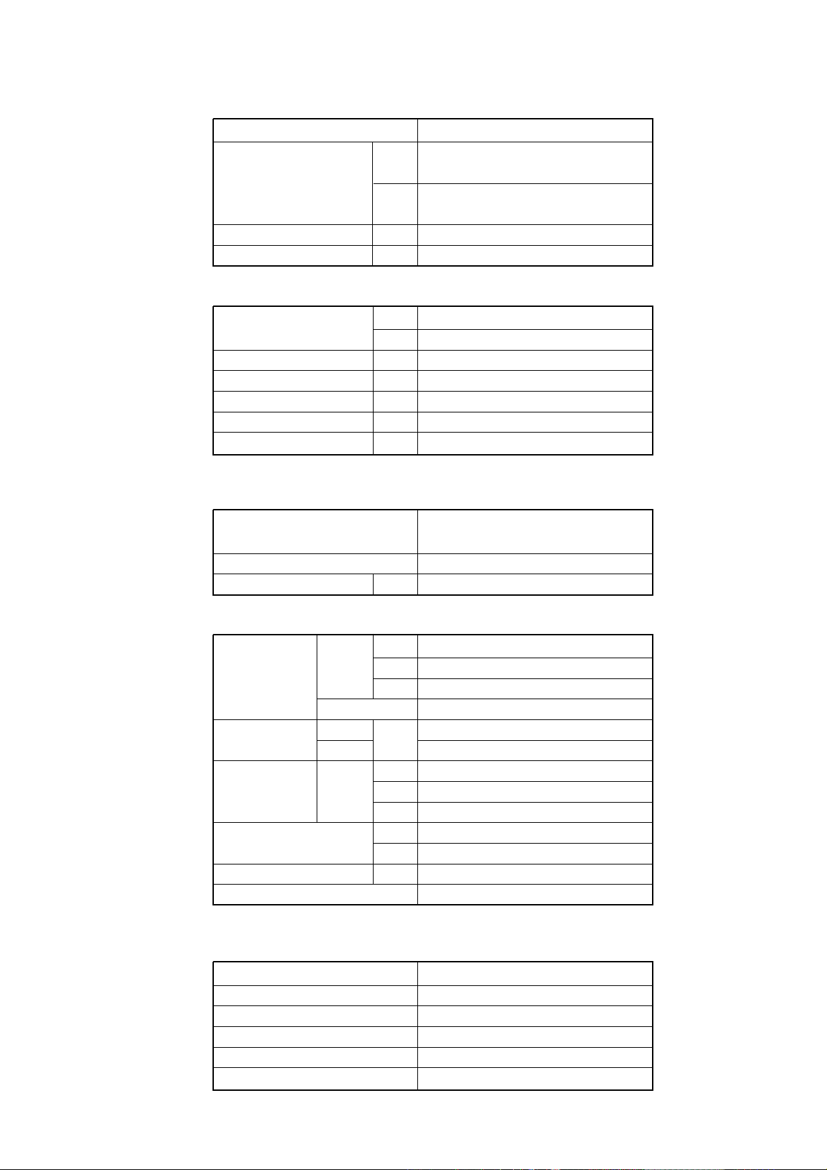
SPECIFICATIONS
TYPE COOLING
IN AUG25ALD-W
MODEL
OUT AOG25AKABL
COOLING CAPACITY kW 7.00 - 7.10
HEATING CAPACITY kW --------
POWER SOURCE
RUNNING CURRENT (A) COOL 12.8 - 13.2
INPUT WATTS (kW) COOL 2.64 - 2.77
E.E.R (kW/kW) COOL 2.65 - 2.56
STARTING CURRENT A 82
MOISTURE REMOVAL r/h 2.5
V 220 - 240
Hz 50
COMPRESSOR
TYPE
CODE AW5532EK - SF
REFRIGERANT R-22 g 2,000
HIGH 490
FAN SPEED INDOOR MED 430
(r.p.m.) LOW 360
OUTDOOR 720
AIR FLOW
DIMENSIONS
H x W x D (mm)
WEIGHT [NET/GROSS] (kg)
MAX PIPE LENGTH/HEIGHT m 25 / 15
REMOTE CONTROLLER TYPE WIRED
INDOOR
OUTDOOR 3,000
NET GRILLE 35 x 940 x 940
m3/h
IN 246 x 830 x 830
OUT 700 x 900 x 350
IN 34 / 44
OUT 67 / 77
Hermetic type, 2 pole,
Single phase, Induction motor
1,100
FULL CHARGE AMOUNT (R - 22)
PIPE LENGTH
7.5 m (25 ft) 2,000
10.0 m (33 ft) 2,050
15.0 m (47 ft) 2,150
20.0 m (66 ft) 2,250
ADDITIONAL CHARGE 20 g / m
- 1 -
AUG25ALD-W
2005.11.15
Page 3
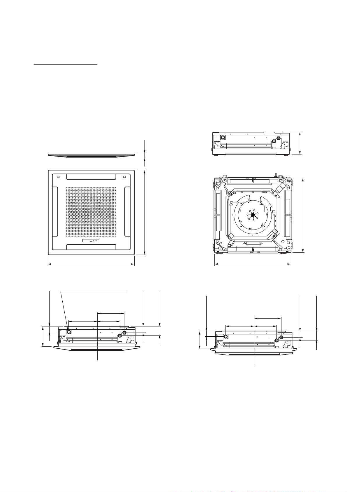
305.5
298.5
248.5
200
60
(Drain pipe)
100
(Small pipe)
70
(Large pipe)
305.5
298.5
248.5
235
60
(Drain pipe)
Draininside Dia. ø32
outside Dia. ø37
100
(Small pipe)
70
(Large pipe)
940
246
30
940 830
830
Model : AUG25ALD-W
OUTLINE AND DIMENSIONS
Unit : (mm)
2005.11.15
- 2 -
Page 4
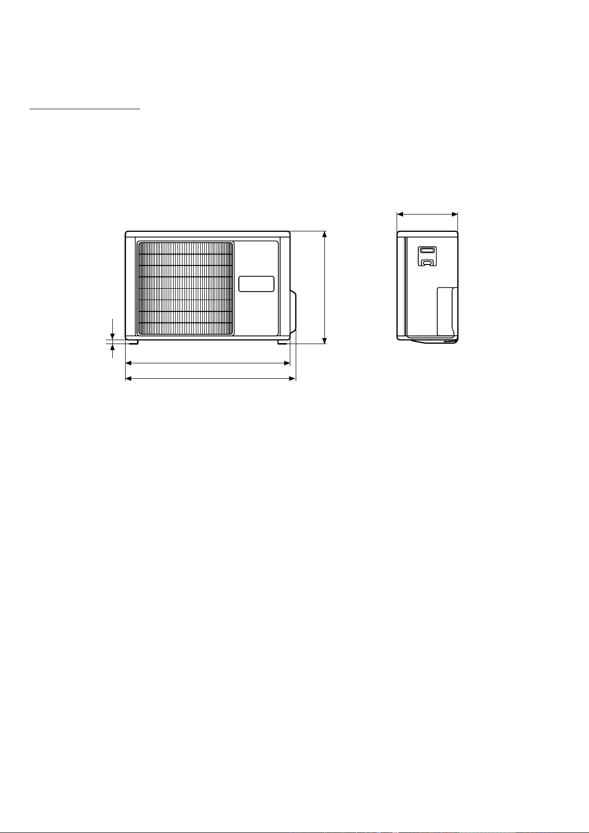
Model :AOG25AKABL
900
15
930
700
350
Unit : (mm)
- 3 -
2005.11.15
Page 5
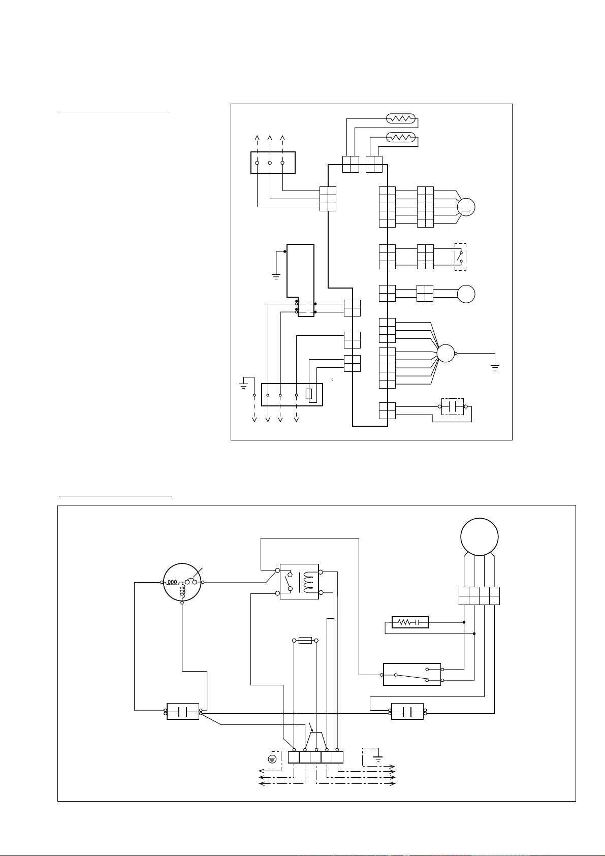
Model : AUG25ALD-W
FLOAT
SWITCH
CN 15
BLACK
BLACK
BLACK
BLACK
PURPLE
BLUE
121
2
3 3
121
2
3 3
CN 10CN 4
STEP
MOTOR
DRAIN
PUMP
MOTOR
FAN MOTOR
CAPACITOR
CONTROL BOARD
THERMISTOR
(PIPE TEMP. )
THERMISTOR
(ROOM TEMP. )
FILTER BOARD
Use T 3A–250V
Fuse on F101
BROWN
RED
121
2
WHITE
WHITE
CN 7
GRAY
GRAY
GREEN
BLACK
WHITE
GRAY
GRAY
GRAY
THERMAL
FUSE 102 C
ORANGE
YELLOW
WHITE
BROWN
RED
ORANGE
YELLOW
WHITE
M
CN 8
BLACK
BLACK
CN 1
WHITE
BLACK
CN 3
3
L
N
12
(N)
TO OUTDOOR UNIT
TERMINAL
CN 6
BLACK
BLACK
YELLOW
YELLOW
FAN
MOTOR
CN 16
BLACK
BLACK
WHITE
RED
1 2
1 2
212
1
212
1
1 2
1 2
GREEN/YELLOW
1
2
3
4
5
1
2
3
4
5
1
2
3
4
5
1
2
3
4
5
CN 5
RED
WHITE
1
2
3
5
6
1
2
3
5
6
1 1
2 2
1 1
2 2
M
1 1
2 2
3 3
FM
CN 19
313
1
123
TO REMOTE
CONTROL UNIT
TERMINAL
CN 17
WHITE
BLACK
RED
212
33
1
CR COMPOSITE
OUTDOOR
THERMOSTAT
C
H
L
COMPRESSOR
CAPACITOR
FAN MOTOR
CAPACITOR
COMPRESSOR
C
S
R
TERMINAL
RED
BLACK
BLACK
BLACK
BLACK
BLACK
WHITE
WHITE
WHITE
L N 3
2
(N)
1
TO INDOOR UNIT
TO POWER SUPPLY
OVERLOAD
PROTECTOR
FUSE 5A
WHITE
BLACK
BLUE
RED
WHITE
WHITE
BLACK
BLUE
RED
FAN
MOTOR
MAIN
RELAY
BROWN
BROWN
6
5
4
1
CIRCUIT DIAGRAM
Model : AOG25AKABL
2005.11.15
- 4 -
Page 6
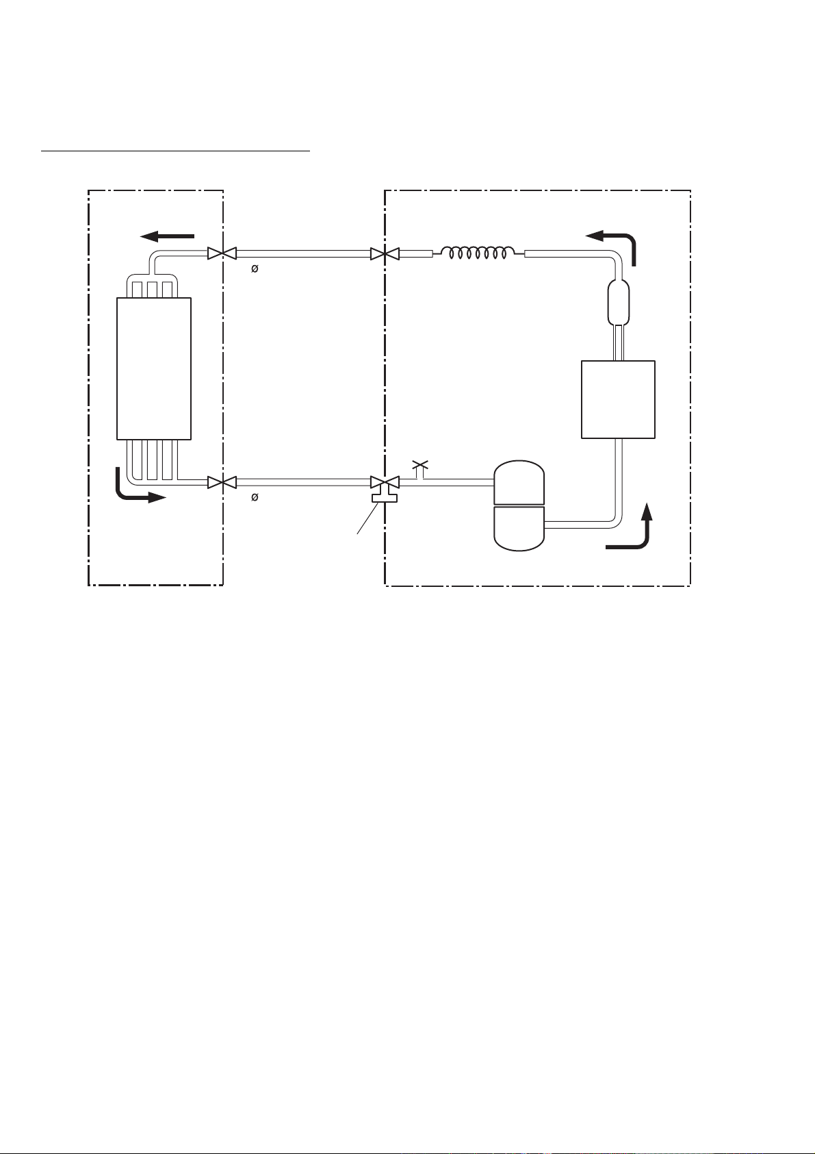
REFRIGERANT SYSTEM DIAGRAM
Dryer
Refrigerant pipe
15.88 mm (5/8")
Refrigerant pipe
9.52 mm (3/8")
Capillary tube
Charging valve
Compressor
OUTDOOR UNIT
Condenser
INDOOR UNIT
Evaporator
Models :AUG25ALD-W / AOG25AKABL
- 5 -
2005.11.15
Page 7

ERROR CONTENTS
1. REMOTE CONTROLLER
Supply power to the crankcase heater 12 hours before the start
of operation in the winter.
For test running, when the remote controller FAN CONTROL button and MASTER CONTROL button are pressed simultaneously
for more than three seconds when the air conditioner is not running, the air conditioner starts and TEST is displayed on the remote controller display.
However, the SET TEMP./DAY setting button does not function,
but all other buttons, displays, and protection functions operate
(Fig. 51).
CLOCK
NON STOP
21
TIMER
MODE
CLOCK ADJUST
When EE:EE blinks at the current time display, there is an error
inside the air conditioner. If the SET TIME button ( ) and SET
TEMP./DAY button ( ) are pressed simultaneously for more than
three seconds, the self diagnosis check will start and the error
contents will be displayed at the current time display (Fig. 52).
When the operation lamp lights, press the START/STOP button
and after operation lamp goes off, perform the same operation
(Fig. 52). Process the error contents by referring to (Table 7).
TEMP
C
HIGH
SET TIME TEMP./DAY FAN
ZONE
SET
CONTROL
ENERGY SAVE
DAY OFF
AUTO
COOL
DEFROST TEST
MASTER
CONTROL
START/STOP
Error code
Error contents
Communication error
(indoor unit remote controller)
Communication error
(indoor unit outdoor unit)
Room temperature sensor open
Room temperature sensor shorted
Indoor heat exchanger temperature sensor open
Indoor heat exchanger temperature sensor
shorted
Outdoor heat exchanger temperature sensor
open
Outdoor heat exchanger temperature sensor
shorted
Power source connection error
Float switch operated
Outdoor temperature sensor open
Outdoor temperature sensor shorted
Discharge pipe temperature sensor open
Discharge pipe temperature sensor shorted
Outdoor high pressure abnormal
Discharge pipe temperature abnormal
Model abnormal
CLOCK
NON STOP
21
TIMER
MODE
CLOCK ADJUST
TEMP
SET TIME TEMP./DAY FAN
ZONE
Stop operation.
Indoor fan abnormal
AUTO
C
HIGH
COOL
DEFROST
CONTROL
MASTER
CONTROL
START/STOP
ENERGY SAVE
SET
DAY OFF
21
TIMER
SET TIME TEMP./DAY FAN
MODE
CLOCK ADJUST
ZONE
SET
AUTO
CONTROL
ENERGY SAVE
DAY OFF
MASTER
CONTROL
START/STOP
Outdoor signal abnormal
Outdoor EEPROM abnormal
2005.09.29
- 6 -
Page 8

2. OUTDOOR UNIT
When the outdoor temperature drops, the outdoor unit's fans may
switch to low speed.
ERROR : HEAT &COOL MODEL (REVERSE CYCLE) ONLY
The LED lamps operate as follows (Table 8) according to the error
contents.
Table 8
Error display
Error contentsLED2LED1
0.1 sec.
ON
OFF
0.5 sec.
ON
OFF
ON
OFF
ON
OFF
2 sec.
0.5 sec.
2 sec.
0.5 sec.
2 sec.
4 quick flash repeated
5 quick flash repeated
6 quick flash repeated
7 quick flash repeated
8 quick flash repeated
0.1 sec.
ON
OFF
Quick flash continuedQuick flash continued
ON
OFF
Lighting continued1 quick flash repeated
ON
OFF
Lighting continued2 quick flash repeated
ON
OFF
Lighting continued3 quick flash repeated
Lighting continued
Lighting continued
Lighting continued
Lighting continued
Lighting continued
Model abnormal or
EEPROM abnormal
Power source
connection error
Discharge temperature
sensor error
Outdoor heat exchanger
temperature sensor error
Outdoor temperature sensor error
Communication signal error
Indoor unit error
Discharge temperature abnormal
High pressure abnormal
When the fault is cleared, the LED lamp goes off.
However, for discharge pipe temperature abnormal and high pressure abnormal, the LED lamp lights continuously for 24 hours, as
long as the power is not turned off.
- 7 -
2005.11.15
Page 9

Model : AUG25ALD-W
THERMAL FUSE
GRAY
GRAY
CN3-2
CN3-1
CN3
53406-9910
DRAIN PUMP
L
TM101
POWER SOURCE
230V
50Hz
N
TM102
FAN CAPACITOR
440V 6uF
UL1015 AWG18 WHITE
UL1015 AWG18 BLACK
FAN MOTOR
TERMINAL BOARD
OUTDOOR UNIT
FH101
UL1015 AWG16
<BET>
E101
GREEN
F M
3
2
1
E
F101
3.15A
R1 3.3
<RGGS-5W>
D1
D3SB60
C5
100/
450V
YELLOW
YELLOW
UL1015 AWG22
UL1015 AWG22
M
FH102
VA1 02
470
<TNR>
SA101
RA-362M
W103
UL1015 AWG22 BLACK
UL1015 AWG22 WHITE
UL1015 AWG22 BLUE
UL1015 AWG22 PURPLE
VA1 01
<TNR>
W104
UL1015 AWG18
UL1015 AWG18 WHITE
CN4
B2P3-VH-B-Y YELLOW
UL1015 AWG20 WHITE
UL1015 AWG20
UL1015 AWG22 RED
CN5
B6P11-VH-B
WHITE
C6
4700P
Q2
2SC1815
BLACK
BLACK
<ECQM>
R7 330
<1/4W>
CN6-2
CN6-1
CN6
B2P3-VH-B-E BLUE
C103
0.01
<F>
C104
0.01
<F>
+
R4 330K
<SPRH-2W>
Q1
2SC4236
R3 100
<1/10W>
R2 1.2
<RSP2-2W>
LF101
ELF20N018A
470
POWER SUPLLY PCB
CN1
B2P3-VH-B-C BLACK
BLACK
CN1-1
CN1-2
CN4-1
CN4-2
WHITE
CN5-1
CN5-2
CN5-6
SL
CN5-5
L
JM5
CN5-3
H
UL1015 AWG18
D5
1SR139-600
D10
1SR139-600
C7 0.047
R6 100
<ECQB>
<1/2W>
D2
D1FL20U
D3
D4
MTZJ5.1B
D1FL20U
C8
+
100/6.3V
K4 G5NB-1A DC12V
C3 0.22 <RE>
R88 120 <1/2W>
C105
0.022
<YE>
C106
C101
0.022
0.22
<YE>
<RE-C>
NO.1
NO.2
NO.3
K3
GDS-1 12V
K1
GDS-1 12V
GRAY
R5 62K
<RSP2-2W>
SWITCHING TRANSFORMER
ZFT29B01
PRIMARY
SW1
DSS803
ZONE CONTROL
SWITCHING
G3MC-202PL-VD DC12V
VA2
470
<TNR>
CN19
B2P3-VH-B-R
RED
CN19-1
INDOOR PRINTED CIRCUIT BOARD
CIRCUIT DIAGRAM
CONTROLLER PCB ASSEMBLY ( MAIN PCB )
EZ-0033WSE-C
R18 1.0K <1/10W>
R19 1.0K <1/10W>
R20 1.0K <1/10W>
C19-C21
0.01 x 3 <F>
NC
R59
R97 R98 R99
10K <1/10W> x 4
5V
C47
C15
C14
+
0.1
0.1
100/
6.3V
R10 10K
<1/10W>
11 6
12
13
5V
CN9
B5P-SHF-1AA
<F>
5V
Q3
DTC124EKA
C10
0.01
<F>
R93-R96
10K <1/10W> x 4
14V
9
5
4
3
21415
8
IC5 (5/7)
uPA2003GR
R25-R28
1.0K <1/10W> x 4
C22-C25
0.01 x 4
<F>
IC5 (1/7)
uPA2003GR
10
IC6 (1/7)
uPA2003GR
6711
<F>
NC
R9 390
<1/10W>
C12
0.01
<F>
JM10
C26-C29
0.01 x 4
<F>
C30
0.01
<F>
CR6
0.01
<F>
5V
1
P15
2
P16
3
P17
I C 1
uPD780058BGC
-0108-8BT-A
52
P120
P122
54
55
P123
66
P05
65
P04
VDD0
74
VDD1
68
75
AVRF 0
7
AVRF 1
AVSS
4
67
VSS0
33
VSS1
71
I C
72
XT2
56
P124
57
P125
58
P126
59
P127
P02
63
P40
19
P41
20
21
P42
40
P64
P63
39
P62
38
P61
37
P60
36
P67
43
44
P30
P31
45
P32
46
P65
41
P36
50
X1
70
1
X1 CSTS0500MG03-T
76
P131
P130
P120
P10
77
P11
28
P51
29
P52
30
P53
31
P54
8
P70
9
P71
10
P72
6
25
P46
15
P24
14
P23
26
P47
35
P57
34
P56
64
P03
27
P50
18
P27
17
P26
16
P25
13
P22
12
P21
11
P20
5
52
51
P37
49
P35
48
P34
47
P33
NC
NC
NC
NC
C32
1000P
<R>
C35
1000P
<R>
R77-R79
10K <1/10W> x 4
116
7
10
5
12
3
14
1
16
R44 1.0K
<1/10W>
IC5 (1/7)
uPA2003GR
11
6
4
13
14V
9
15
2
8
R46 1.0K
<1/10W>
R50 10K <1/10W>
4
3
2
1
IC4 (7/7)
uPA2003GR
R43
10K (1%)
<1/10W>
R45
49.9K (1%)
<1/10W>
D0
VCC
NC
D1
CK
NC
GND
CS
IC7
BR93LC46RF
5V
5V
Q6
2SC2712
10
IC6 (1/7)
uPA2003GR
R52
10K
<1/10W>
CR1-CR5
10K <1/10W> x 5
P121
R51 1.0K
R60
10K
<1/10W>
Q5
2SC2712
5V
<1/10W>
R61
10K
<1/10W>
7
32
P55
61
P00
53
62
P01
78
P12
79
P13
80
P14
P66
42
R70
24
P45
23
P44
22
P43
C31
73
XT1
R55 10K
<1/10W>
60
RESET
X2
69
2
C44
0.1
<F>
3
C43
C16
0.01 <F> x 3
5V
R81 1.0K <1/10W>
R72 1.0K <1/10W>
R71 1.0K <1/10W>
RJ2 1.0K
<1/10W>
RJ1 1.0K
<1/10W>
C49
5V
0.01
<F>
1
3
IC8
2
PST600C
12V
R62 4.7K
<1/10W>
IC11-2
BA10358
R65 390
<1/10W>
R69
R80
NO.3
5V
NO.2 INDOOR ROOM FAN SWITCHING
NO.1
C45
0.1
<F>
R63
15.4K (1%)
<1/10W>
+
-
D7
DA226U
5V
10K <1/10W> x 3
SW4
DSS803
INDOOR ROOM FAN SWITCHING
ROOM TEMPERATURE CORRECTION
( COOLING OPERATION )
CN15
B3B-XARK-1-A
RED
R15-R17
10K <1/10W> x 3
NOT USED
REMOTE CONTROL
CUSTOM CODE SWITCHING (R1)
REMOTE CONTROL
CUSTOM CODE SWITCHING (R2)
T1
D6
D2FL20U
C9
1000
/25V
SECONDARY
C54 0.01 <F>
R11
56K
<1W>
D8
D1F60
TLP621
(D4)-GB
R39 10K
SSR1
+
-
K8
G5N-1A
CR8
TA120C33
5V
JM1
JM2
JM3
IC2
7812
I
O
G
+
R8 10K
<1/10W>
IC3
7805
I
O
G
5V
SW2
DRS4016-5
8
4
2
1C
5V
IC9
R12 1.0K
<1/10W>
R13 10K
<1/10W>
5V
R38 10K
<1/10W>
<1/10W>
ROOM TEMPERATURE CORRECTION
( HEATING OPERATION )
ROOM TEMPERATURE CORRECTION
( HEATING OPERATION )
C18
0.01
<F>
R37 10K
<1/10W>
R42 1.0K <1/10W>
R41 1.0K <1/10W>
R40 1.0K <1/10W>
14V
R21-R24
10K <1/10W> x 4
TEST
CN9-1
CN9-2
CN9-3
CN9-4
CN9-5
12V14V
C11
+
10/
25V
C13
0.1
<F>
R29-R32
10K <1/10W> x 4
R33-R36
1.0K <1/10W> x 4
C17
0.01
<F>
K 4
8
7
6
5
5V
C39
0.1
<F>
12V
R64
28.0K (1%)
<1/10W>
12V
IC11-1
BA10358
+
-
NO.3
NO.2
NO.1
CN15-1
CN15-2
CN15-3
C34
0.1
<F>
C37
0.1
<F>
10K <1/10W> x 4
R58
IC6 (5/7)
uPA2003GR
5
3
1
12V
R66 10K
<1/10W>
UL1430 AWG22
R75 R76
R100
12
4
13
14V
14
9
15
2
8
16
L2
CN17-1
L4
CN17-2
L3
CN17-3
TERMINAL BOARD
5V
K 8
BLACKUL1430 AWG22
BLACK
5V
C38
0.01
<F>
CN10
B5B-XASK-1-A
14V
CN17
B3B-XAKK-1-A
BLACK
BLACK
UL1430 AWG22
UL1430 AWG22 WHITE
321
REMOTE
CONTROL UNIT
FLOAT SWITCH
CN8
B2B-XASK-1-A
CN8-1 BLACK
CN8-2
CN7-1
CN7-2
CN8
B2B-XAKK-1-A
BLACK
Q4
DTC124EKA
5V
R49 1.0K
<1/10W>
R68 10K
<1/10W>
CR7
R67 1.0K
0.01
<1/10W>
<F>
14V
CN10-1
CN10-2
CN10-3
CN10-4
CN10-5
UL1430 AWG22 RED
ROOM TEMPERATURE THERMISTOR
BLACK
PIPE TEMPERATURE THERMISTOR
GRAY
GRAY
5V
R48
10K
<1/10W>
R47 390
<1/10W>
5V
C1
0.1
CN16-1
<F>
CN16-2
CN16-3
UL1430 AWG22
CN16
B3P-VH-B
BROWN
RED
ORANGE
YELLOW
WHITE
UL1430 AWG28
BROWN
RED
ORANGE
YELLOW
WHITE
CN14
B4B-XH-AM
RED
WHITE
BLACK
CN14-4
CN14-3
HA
JEM-A
CN14-2
CN14-1
F M
FEED BACK
LOUVER
( UP / DOWN )
M
2005.11.15
- 8 -
Page 10

DISASSEMBLY ILLUSTRATION
Model :
690
847
834-2
705
AUG25ALD-W
847
692
692
543
692
122
847
122
690
543
544
544
847
122
544
522
543
122
692
847
876-2
338
847
226
122
692
690
543
692
847
542
705
544
545
240
469 468
245
472-4
487
472-5
481
472-5
472-2
481-1
858
777-2
93
481
71
481
472-3
472-5
472-5
472-1
71
858
777-1
2005.11.15
710
61
- 9 -
Page 11

479
467
127
835
482
798
835
484
465
244
235
998
155
903
904
563
814
484
484
464
462
164
484
168
474
735
477
197
197
565
223
457
488
160
457
514
329
999
138
187
803
187
460-1
184-1
834-1
337-1
146-2
146-1
337-1
337-2
117-3
476-2
143-3
460-2
Model :
AUG25ALD-W
- 10 -
2005.11.15
Page 12

Model :
AUG25ALD-W
143-1
875
34
815-2
629
541
195
381
628
824-3
815-1
234
982-1
236
2005.11.15
- 11 -
Page 13

527
734
477
64
7
9
84
5
4
2
Model :
AOG25AKABL
- 12 -
2005.11.15
Page 14

41
39
45-2
45-3
45-1
45-4
646
26
744
817
983
111
109
29
653-1
12
107
46
55
108
Model :
AOG25AKABL
2005.11.15
- 13 -
Page 15

815
187
355
549
187
32
37
38
989-1
989-2
824-4
823-2
880-2
218-3
34
Model :
AOG25AKABL
- 14 -
2005.11.15
Page 16

19-3
19-2
19-2
13-2
13-1
16
17
15
54
85
55
46
12
18
20
108
107
Model :
AOG25AKABL
2005.11.15
- 15 -
Page 17

INDOOR UNIT
Ref.
No.
34 Capacitor (Fan Motor) 9900270216
61 Decoration Plate 9363131000
71 Grille Hook Holder 9362782005
93 Filter 9362766005
122 Louver Support Holder 9362799003
127 Drain Hose 9365074008
138 Separate Wall 9362793001
143-1 Clamp NK-3N 313361274700
146-1 Evaporator-A Assy 9368196004
146-2 Evaporator-B Assy 9368197001
155 Special Nut M6 9307615016
160 Drain Pan Assy 9362804004
164 Fan Motor Assy-In 9601558019
168 Cabinet-E 9362735001
184-1 Thermostat Spring-A 313728262708
187 Clamp No. 1219 313361271706
195 Clamp SKB-100 313361275805
197 Wind Guide Board 9363117004
223 Control Box 9362762007
226 Motor Gear 9362764001
Description
Part No.
AUG25ALD-W
PA R TS LIST
When you order parts, please make a photocopy of this page
and fill the number of the parts in the "Order" column.
Ord.
Ref.
Q'ty
No.
476-2 Special Washer 9362756006
477 Bellmouth (B) 9362774000
479 Float Switch 9703285004
481 Insulation (Grille)-A 9362780001
481-1 Insulation (Grille)-B 9362781008
482 Pump Unit 9703125010
484 Hook 9362736008
487 Grille Hinge Wire 9362754002
488 Drain Pan Plug 313005174654
514 Control Box Cover 9362763004
522 Joint Gear 9362772006
541 Terminal Plate 9363642001
542 Panel Base 9362759014
543 Holder (Panel Frame) 9362761017
544 Holder (Panel Base) 9362760010
545 Panel Base 9362759014
563 Insulation (I nner Box) 9362797009
565 Evaporator Holder Assy 9362802024
628 Locking Spacer-B 313005446558
629 EMI Filter 0400247074
Description
Part No.
AUG25ALD-W
Ord.
Q'ty
234 Thermistor Assy-R oom 9703299025
235 Thermistor Assy-Pipe 9703297014
236 Controller PCB Assy 9704557339
240 Remote Control Unit 9371438023
244 Pipe Cover 9362748001
245 Cable Clamp 313714181904
329 Coupling Pipe Assy 9368204006
337-1 Reinforcement (Evaporator)-A 9362749008
337-2 Reinforcement (Evaporator)-B 9362750004
338 Motor Holder 9362765008
381 Locking Spacer 313209391506
457 R einforcement (Drain Pan) 9362757003
460-1 Pump Cover-A 9362775007
460-2 Pump Cover-B 9362776004
462 Top Cover Plate Assy 9362806022
464 Cabinet-A Assy 9362807012
465 Cabinet-B Assy 9362808019
467 Drain Port 9362786003
468 Special Nut-A (Large) 313005446653
469 Special Nut-B (Small) 313005446759
472-1 Grille Reinforcement-A 9362738002
472-2 Grille Reinforcement-B 9362739009
Grille Reinforcement-C 9362740005
472-3
472-4 Grille Reinforcement-D 9362741002
472-5 Grille Reinforcement-E 9362742009
Tubo Fan Assy 9362810012
474
690 Joint-A 9362773003
692 Joint S haft 9362771009
705 Louver Sub Assy 9362836012
710 Intake Grille 9362767019
735 Distributor Assy 9368198008
777-1 Hook (Grille)-A 9362779012
777-2 Hook (Grille)-B 9362778015
798 Drain Pump Holder 9362753005
803 Cabinet-D 9362792004
814 Cabinet-C 9362791007
815-1 Terminal-3P 9306489069
815-2 Terminal-3P 9703345012
824-3 Fuse 0600222512
834-1 Wire Cover-A 9362789004
834-2 Wire Cover-B 9362788007
835 Cushion Pump 9362777001
847 Louver Supporter 9362770019
858 Spring Grille 9362755009
875 Filter PCB Assy 9704561107
876-2 Motor, Step 9360307019
903 Rubber (Vibration-proof)-A 9364891002
904 Rubber (Vibration-proof)-B 9364892009
Clamp (Cord) 9356857009
982-1
998 Bypass Pipe-A 9368207007
999 Bypass Pipe-B 9368208004
- 16 -
2005.11.15
Page 18

OUTDOOR UNIT
Ref.
No.
2 Fan Cover (Guard) 9371187013
4Emblem-Rear 313791088308
5 Cabinet-A, Painted 9359797043
7Connector Cover 9358011010
9 Cabinet-B, Painted 9361323025
12 Base Assy, Painted 9359812029
13-1 3-Way Valve Assy 9374851065
13-2 2-Way Valve Assy 9374829026
15 Dryer 9368111014
16 Condenser Assy 9365636008
17 U Pipe-Y 9305523009
18 Suction Pipe 9365610008
19-2 Joint Pipe (Capillary) 9365621004
19-3 Capillary Tube 9365622001
20 Discharge Pipe Assy 9365618004
26 Compressor Cover-A 9365426005
29 Separate Wall 9359805014
32 Control Box Metal-A 9361409026
34 Capacitor (Fan Motor) 9900270049
37 Running Capacitor 9703107122
Description
AOG25AKABL
Part No.
When you order parts, please make a photocopy of this page
and fill the number of the parts in the "Order" column.
Ord.
Ref.
Q'ty
No.
54 Condensing Pipe 9365620007
55 Special Nut M8 (For Comp. ) 9355091008
64 Cabinet Left 9359840046
84 Valve Cover 9361325012
85 Valve Fixing Plate Metal 9361324015
107 R ubber S eat-A (For Comp. ) 313093081402
108 Sleeve-A (For Comp. ) 313093081706
109 Terminal Cover (For Comp. ) 313202059600
111 Terminal Packing (For Comp. ) 313202059807
187 Clamp No. 1219 313361271706
218-3 Power Relay 9900074012
355 Switch Bracket 313986353607
477 Bellmouth 9359809012
527 Protection Net 9359845027
549 Thermostat Outdoor 9352553004
646 Compressor Cover-B 313986355101
653-1 Bolt (Fan Motor Fixing) 0700145148
734 Cabinet Top Plate 9359799023
744 Clamp (Condenser) 313166374106
815 Terminal-5P 9900203023
Description
Part No.
AOG25AKABL
Ord.
Q'ty
38 Capacitor Clamp 9351770013
39 Propeller Fan 9359837015
41 Fan Motor Assy-Out 9601754015
45-1 Motor Bracket-A 9369627002
45-2 Motor Bracket-B 9371439013
45-3 Motor Bracket-C 9373096018
45-4 Motor Bracket-D 9369630002
46 Compressor Ass y 9364340005
817 Thermostat Fixture 9352164019
823-2 Fuse Holder 0500063024
824-4 Fuse 0600222529
880-2 Network 9701020010
983 Thermostat Cover 9358274002
989-1 Double Clamp-U 9374175017
989-2 Double Clamp-L 9374176014
2005.11.15
- 17 -
Page 19

STANDARD ACCESSORIES
INDOOR UNIT ACCESSORIES
Name and Shape
Coupler heat insulation
Remote control unit
cord clamp
Binder
Screw
Special nut A
(large flange)
Special nut B
(small flange)
Part No.
9350716029
9352766015
313714181904
313035356905 (Large)
313361275805 (Small)
(A) For installing the
mounting bracket
0700019067
(B) For installing the cord
clamp
0700235016
313005446653
313005446759
1 each
}
Remote control unit
Template
Blower cover insulation
Hook wire
OUTDOOR UNIT ACCESSORIES
Name and Shape Q'ty
Hexagon wrench
1
(Cooling model)
9371438023
9363173000
9363265002
9363168006
Application
For opening the refrigerant valve on
the outdoor unit
Parts No.
9351228019
Drain pipe
Drain cap
1
For outdoor unit drain piping work
[Heat & Cool (Reverse cycle) model
only]
2
- 18 -
9303029015
313166024302
2005.11.15
Page 20

0509J2916
 Loading...