

Page 1
CASSETTE TYPE
AIR CONDITIONER
(25,000 / 30,000 BTU/h)
TECHNICAL MANUAL
Page 2

CONTENTS
1. FEATURES.........................................................................2
2. OUTLINE AND DIMENSIONS............................................3
2.1 INDOOR UNIT..................................................................... 3
2.2 OUTDOOR UNIT.................................................................. 4
2.3 REMOTE CONTROLLER.................................................... 5
3. DATA...................................................................................6
3.1 PERFORMANCE CURVE .................................................... 6
3.2 TEMPERATURE RANGE .................................................... 7
3.3 ADDITIONAL REFRIGERANT CHARGE........................... 7
3.4 AIR VELOCITY DISTRIBUTION......................................... 8
3.5 DUCT CONNECTION ....................................................... 10
3.6 REFRIGERANT SYSTEM DIAGRAM .............................. 11
3.7 NOISE LEVEL CHECK POINTS ..................................... 13
4. SPECIFICATIONS............................................................16
Page 3

1. FEATURES
Flexible installation
Small and compact body
allows space saving installation
New mechanism allows the
cassette body to move 35mm
downward and contributes to keeping
the ceiling surface clean
235 min.
Standard setting
Width
940
Slender setting
Height
940
Depth
200 min.
Improvement of noise level and air distribution
Comparison of noise level (dB)
Noise level is drastically reduced by bigger caliber turbo-fan and larger air flow passage.
Height
Width
Depth
Setting space
200 or 235
840
840
Improvement of fan blade
Old fan (8 blades)
230
400
(Unit : mm)
Wide air flow
Larger air flap distributes the outlet air flow a longer distance in the horizontal direction
Old model
New fan (7 blades)
New model
– 2 –
350.5
(Unit : mm)
450
Page 4
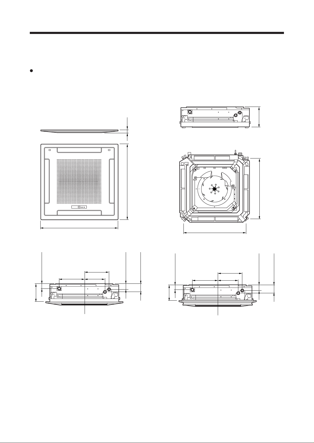
2. OUTLINE AND DIMENSIONS
2.1 INDOOR UNIT
MODELS : AUG25A, AUG25R, AUG30A, AUG30R
30
(Unit : mm)
245
60
235
940
Drain inside Dia. ø32
outside Dia. ø37
298
(Drain pipe)
305
248
940
100
70
(Large pipe)
(Small pipe)
200
60
(Drain pipe)
305
750
298
248
750
100
70
(Large pipe)
(Small pipe)
– 3 –
Page 5
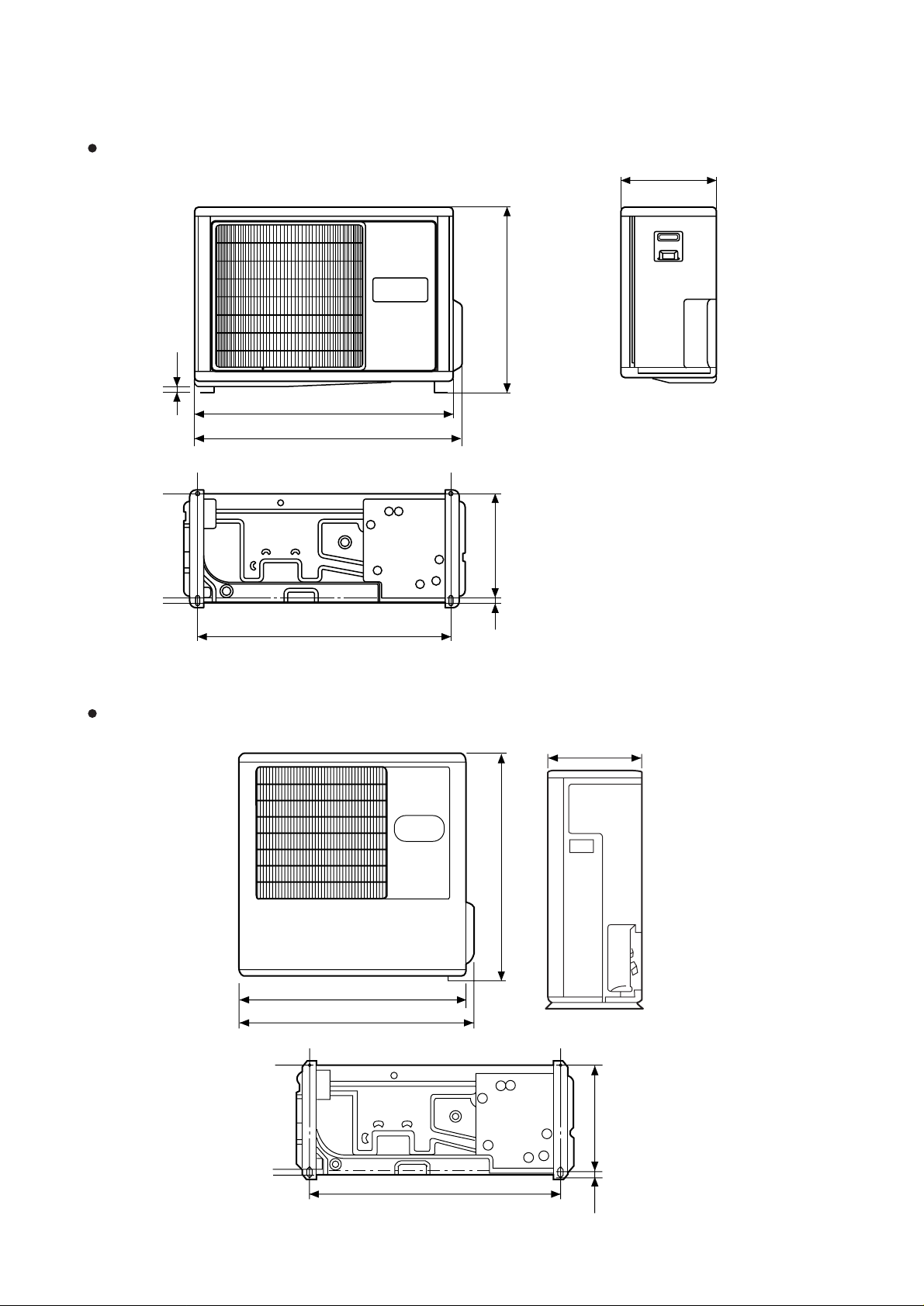
2.2 OUTDOOR UNIT
MODELS : AOG25A, AOG25R
15
900
930
(Unit : mm)
350
700
333
804
MODELS : AOG30A, AOG30R
900
930
19
350
900
804
333
19
– 4 –
Page 6
MASTER
CONTROL
FAN
CONTROL
TIMER
MODE
TEMP./DAY
SET TIME
CLOCK ADJUST
START/STOP
COOL
FAN
HEAT
TEMP.
C
DEFROST TEST
DAY
DAY OFF
CLOCK
OFF
ON
OFF
ON
NEXT DAY
TIMER
NON STOP
OFFON
WEEKLY
TIMER
1
2
AUTO
LOW
MED
HIGH
AUTO
SET
ZONE
DAY OFF
ENERGY SAVE
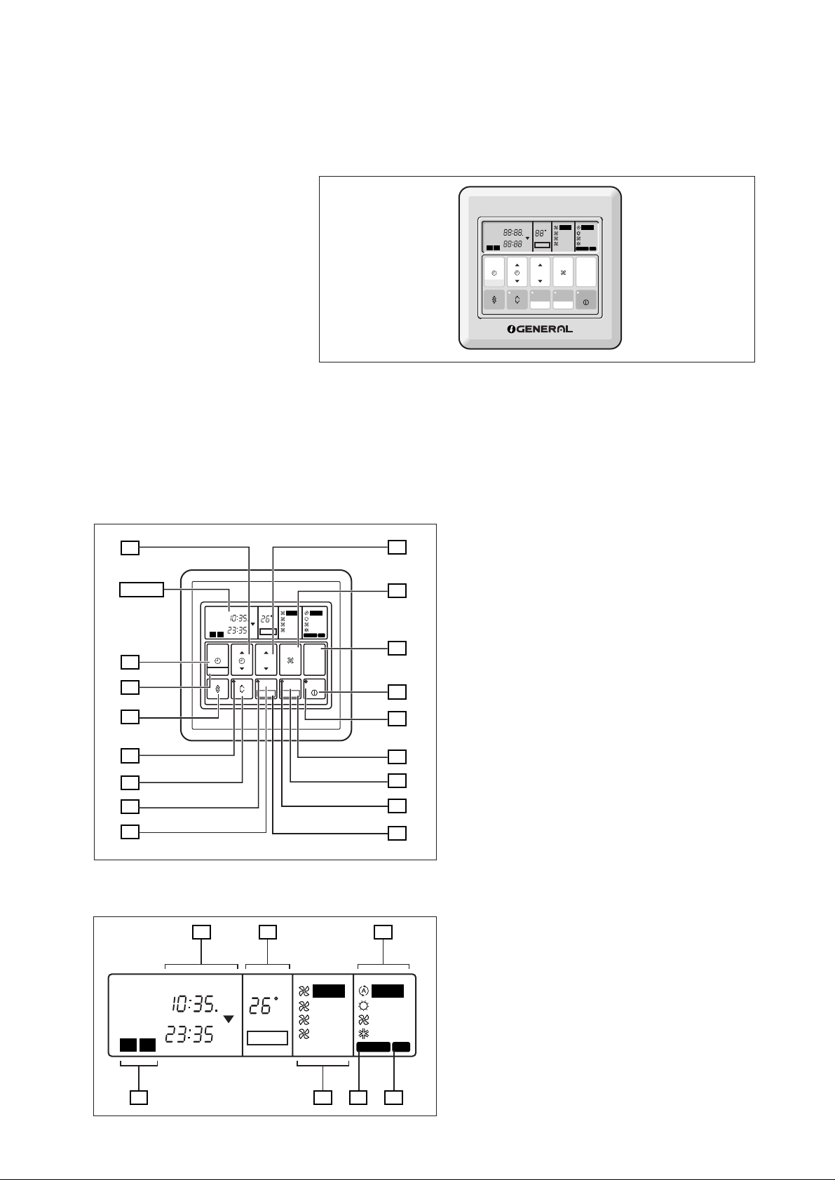
2.3 REMOTE CONTROLLER
WIRE REMOTE CONTROLLER WITH WEEKLY TIMER
FEATURES
Three kinds of timer setup (OFF/ON/WEEKLY) are possible.
Function of weekly timer
Setting of different on-off time by day.
Setting of set on-off time twice a day.
Setting of time in 5 minute steps.
Timer operation of a reserved day can be temporarily cancelled by pushing the “DAY OFF” button.
Time setting can be left until the next day.
14
Display
13
12
11
10
9
8
7
Display panel
NON STOP
OFFON
TIMER
WEEKLY
1
21
2
CLOCK
TIMER
NEXT DAY
NON STOP
OFFON
TIMER
WEEKLY
2
1
TIMER
MODE
CLOCK ADJUST
OFF
ON
ON
OFF
CLOCK
TIMER
NEXT DAY
SET TIME
TEMP.
OFF
C
ON
DAY
ON
DAY OFF
OFF
TEMP./DAY
CONTROL
ENERGY SAVE
ZONE
SET
DAY OFF
1918
TEMP.
C
DAY
DAY OFF
AUTO
HIGH
MED
LOW
FAN
AUTO
HEAT
FAN
COOL
DEFROST TEST
MASTER
CONTROL
START/STOP
AUTO
HIGH
MED
LOW
15
16
17
20
AUTO
HEAT
FAN
COOL
DEFROST TEST
2322
24
1
2
3
4
5
6
– 5 –
1 START/STOP Button
Pressed to start and stop operation.
2 OPERATION Lamp
Lights during operation and when the timer is on.
3 DAY OFF Button
Temporary cancellation of one day timer.
4 ENERGY SAVE Button
Turns energy efficient mode on and off.
5 ENERGY SAVE Lamp
Lights up when the unit is in the energy save mode.
6 SET Button
Sets the date, hour minute and on-off time.
7 ZONE Button
Use to turn the zone control on and off.
8 ZONE Lamp
Lights up when the units is in the zone control mode.
9 VERTICAL SWING Button
10 VERTICAL SWING Lamp
11 VERTICAL AIR FLOW DIRECTION Button
12 CLOCK ADJUST Button
13 TIMER MODE Button
Changes the timer mode (NON STOP, OFF TIMER,
ON TIMER, WEEKLY TIMER).
14 SET TIME Button
Sets the current time and on-off time.
15 TEMP./DAY Button
Sets the indoor temperature / days.
16 FAN CONTROL Button
Selects the fan speed (AUTO, HIGH, MED, LOW).
17 MASTER CONTROL Button
Selects the operating mode
(AUTO, HEAT, FAN, COOL).
18 Clock Display
19 Set Temperature / Day Display (TEMP./DAY)
20 Operation Mode Display
21 Timer Mode Display
22 Fan Speed Display
23 DEFROST Display
24 TEST Display
Page 7

3. DATA
3.1 PERFORMANCE CURVE
AUG25A, AUG30A
120
110
100
Capacity (%)
90
80
70
100
90
80
Total input (%)
0 5 10 15 20 25 30 35 40 45 50 52
Cooling
Low ambient operation model
OUTDOOR DB (°C)
Indoor
DB/WB (°C)
31/22
27/19
23/16
19/12.5
31/22
27/19
23/16
19/12.5
AUG25R, AUG30R
Cooling
120
110
100
Capacity (%)
90
80
70
100
90
80
Total input (%)
0 5 10 15 20 25 30 35 40 45 50 52
Low ambient operation model
OUTDOOR DB (°C)
Indoor
DB/WB (°C)
31/22
27/19
23/16
19/12.5
31/22
27/19
23/16
19/12.5
120
110
100
Capacity (%)
90
80
70
100
90
80
Total input (%)
-5 0/-2 5/3
OUTDOOR DB/WB (°C)
Heating
10/9.5 15/12
15
20 21/
Indoor
DB (°C)
20
25
25
20
15
17.5
– 6 –
Page 8

3.2 TEMPERATURE RANGE
MODEL
TEMPERATURE RANGE
Indoor Unit Outdoor Unit
AUG25A
COOL 18°C to 32°C 00°C to 52°C
AUG30A
AUG25R
AUG30R
COOL 18°C to 32°C 00°C to 52°C
HEAT 30°C or less –5°C to 21°C
3.3 ADDITIONAL REFRIGERANT CHARGE
PIPE LENGTH
FULL
CHARGE
AMOUNT
AUG25A
AUG25R
AUG30A
AUG30R
5m 7.5m 10m 15m 20m 25m 30m Additional
(16ft) (25ft) (33ft) (49ft) (66ft) (82ft) (99ft) refrigerant
2,000g(070.5oz) 2,030g(071.6oz) 2,060g(072.7oz) 2,120g(074.8oz) 2,180g(076.9oz) 2,240g(079.0oz) –––––
2,100g(074.1oz) 2,225g(078.5oz) 2,350g(082.9oz) 2,600g(091.7oz) 2,850g(100.5oz) 3,100(109.3oz) –––––
2,650g(093.5oz) 2,693g(095.0oz) 2,778g(098.0oz) 2,831g(099.9oz) 2,916g(102.9oz) 3,001g(105.9oz)
2,700g(095.2oz) 2,825g(099.6oz) 3,075g(108.5oz) 3,325g(117.3oz) 3,575g(126.1oz) –––––
12g/m
(0.4oz/3.3ft)
50g/m
(1.41oz/3.3ft)
17g/m
(0.6oz/3.3ft)
50g/m
(1.41oz/3.3ft)
AUG25A, AUG25R, AUG30A, AUG30R
Pipe size : Liquid 9.52 mm (3/8") Gas 15.88 mm (5/8")
100
90
Capacity (%)
80
70
5 101520253035
Connection pipe length (m)
82%
Plotted under additional
refrigerant charge conditions.
– 7 –
Page 9

3.4 AIR VELOCITY DISTRIBUTION
AUG25A, AUG25R
4–WAY AIR OUTLET
(m)
3
2
1
0
1
2
3
8765432
(m)
2
1
0
87
UNIT : m/s
0.5
0.25
1
2
0.25
210.5
2
1
0.5
2 1 0.5 0.25
0.25
1012345678
UNIT : m/s
2
1
0.5
0.25
2
1
0.5
0.25
654321012345678
Note :
Condition
Fan speed : High
Operation mode : FAN
Voltage : 240V
TOP VIEW
AIR FLOW DIRECTION
: Upward
(m)
SIDE VIEW
AIR FLOW DIRECTION
: Upward
(m)
(m)
2
1
0
2–WAY AIR OUTLET
(m)
0.5
0.25
21012
1
0
1
87654321012345678
(m)
2
1
0
0.25
87654321012345678
UNIT : m/s
2
1
0.5
2
1
0.5
0.25
210.50.25 2 1 0.5 0.25
2
1
SIDE VIEW
HORIZONTAL LOUVER
(m)
2
: Downward
1
0.5
UNIT : m/s
TOP VIEW
AIR FLOW DIRECTION
: Upward
(m)
UNIT : m/s
SIDE VIEW
AIR FLOW DIRECTION
: Upward
0.25
(m)
– 8 –
Page 10

AUG30A, AUG30R
4–WAY AIR OUTLET
(m)
3
2
1
0
0.25
1
2
3
8765432
(m)
2
1
0
87
0.25
UNIT : m/s
0.5
0.25
1
2
211 0.50.5 0.25
2
1
0.5
2
0.25
1012345678
UNIT : m/s
2
1
0.5
2
1
0.5
0.25
654321012345678
Note :
Condition
Fan speed : High
Operation mode : FAN
Voltage : 240V
TOP VIEW
AIR FLOW DIRECTION
: Upward
(m)
SIDE VIEW
AIR FLOW DIRECTION
: Upward
(m)
(m)
2
1
0
2–WAY AIR OUTLET
(m)
0.5 0.5
0.25 0.25
21012
1
0
1
87654321012345678
(m)
2
1
0
0.25
87654321012345678
UNIT : m/s
22
11
210.50.25 2 1 0.5 0.25
1
0.5
SIDE VIEW
HORIZONTAL LOUVER
: Downward
(m)
UNIT : m/s
TOP VIEW
AIR FLOW DIRECTION
: Upward
(m)
UNIT : m/s
2
2
1
0.5
0.25
SIDE VIEW
AIR FLOW DIRECTION
: Upward
(m)
– 9 –
Page 11

3.5 DUCT CONNECTION
OUTLET AIR
10
9
(mmAq)
(mmAq)
8
7
6
5
4
3
2
1
0
012345
10
9
8
7
6
5
4
3
2
1
0
0
240V Hi
220V Hi
220V Lo
Duct
(Inside Dia. ø100mm)
L
L=5m
240V Lo
240V Hi
220V Hi
240V Lo
220V Lo
12345
(m
(m
3
/min)
3
/min)
L=3m
L=1m
Duct
(Inside Dia. ø100mm)
L
L=5m
L=3m
L=1m
FRESH AIR
(mmAq)
Static pressure
required to take
in fresh air
Duct
(Inside Dia. ø70mm)
P
Duct Fan
7
6
5
4
3
2
1
0
0
0.1 0.2 0.3 0.4 0.5 0.6
– 10 –
(m
3
/min)
Page 12

3.6 REFRIGERANT SYSTEM DIAGRAM
Models : AUG25A / AOG25A
OUTDOOR UNIT INDOOR UNIT
Dryer
Compressor
Capillary tube
Refrigerant pipe
ø 15.88mm(5/8")
Charging valve
EvaporatorCondenser
Refrigerant pipe
ø 9.53mm(3/8")
Charging valve
Models : AUG25R / AOG25R
OUTDOOR UNIT INDOOR UNIT
Charging
valve
4-Way
valve
Muffler
Accumulator
Compressor
Dryer
Refrigerant pipe
ø 15.88mm(5/8")
EvaporatorCondenser
Strainer
Capillary
tube
Charging
valve
– 11 –
Refrigerant pipe
ø 9.53mm(3/8")
: COOL
: HEAT
Page 13

Models : AUG30A / AOG30A
OUTDOOR UNIT INDOOR UNIT
Muffler
Dryer
Compressor
Capillary tube
Refrigerant pipe
ø 15.88mm(5/8")
Accumulator
Charging valve
EvaporatorCondenser
Refrigerant pipe
ø 9.53mm(3/8")
Models : AUG30R / AOG30R
OUTDOOR UNIT INDOOR UNIT
Pressure
check valve
Charging
valve
4-Way
valve
Muffler
Compressor
Capillary
tube
Accumulator
Strainer
Refrigerant pipe
ø 15.88mm(5/8")
EvaporatorCondenser
Distributor
Dryer
Refrigerant pipe
ø 9.53mm(3/8")
: COOL
: HEAT
– 12 –
Page 14

3.7 NOISE LEVEL CHECK POINTS
INDOOR UNIT
1.5 m
OUTDOOR UNIT
h
1 m
AIR
h
2
– 13 –
Page 15

AUG25A, AUG25R
Old octave-band limiting frequencies, Hz
4,800
9,600
2,400
4,800
1,200
2,400
600
1,200
300
600
150
300
75
150
75
Below
1957 Noise Criteria
NC Curves
NC-65
NC-60
NC-55
NC-50
NC-45
NC-40
NC-35
NC-30
NC-25
NC-20
NC-15
New octave-band center frequencies, Hz
63 125 250 500 1,000 2,000 4,000 8,000
4,800
9,600
2,400
4,800
1,200
2,400
600
1,200
300
600
80
70
1957 Noise Criteria
NC Curves
NC-65
60
NC-60
NC-55
50
NC-50
NC-45
40
NC-40
NC-35
30
NC-30
NC-25
20
Octave-band sound-pressure level dB: (0dB=0.0002µbar)
NC-20
10
NC-15
0
AUG30A, AUG30R
Old octave-band limiting frequencies, Hz
150
75
Below
300
150
75
80
70
60
50
– 14 –
40
30
20
New octave-band center frequencies, Hz
63 125 250 500 1,000 2,000 4,000 8,000
Octave-band sound-pressure level dB: (0dB=0.0002µbar)
10
0
Page 16

AOG25A, AOG25R
Old octave-band limiting frequencies, Hz
4,800
9,600
2,400
4,800
1,200
2,400
600
1,200
300
600
150
300
75
150
75
Below
1957 Noise Criteria
NC Curves
NC-65
NC-60
NC-55
NC-50
NC-45
NC-40
NC-35
NC-30
NC-25
NC-20
NC-15
New octave-band center frequencies, Hz
63 125 250 500 1,000 2,000 4,000 8,000
4,800
9,600
2,400
4,800
1,200
2,400
600
1,200
300
600
80
70
1957 Noise Criteria
NC Curves
NC-65
60
NC-60
NC-55
50
NC-50
NC-45
40
NC-40
NC-35
30
NC-30
NC-25
20
NC-20
Octave-band sound-pressure level dB: (0dB=0.0002µbar)
10
NC-15
0
AOG30A, AOG30R
Old octave-band limiting frequencies, Hz
150
75
Below
300
150
75
80
70
60
50
– 15 –
40
30
20
New octave-band center frequencies, Hz
63 125 250 500 1,000 2,000 4,000 8,000
Octave-band sound-pressure level dB: (0dB=0.0002µbar)
10
0
Page 17

4. SPECIFICATIONS
TYPE COOLING TYPE COOLING & HEATING TYPE
MODEL
POWER SOURCE V/ /Hz 220-240/1/50 220-240/1/50 220-240/1/50 220-240/1/50
COOLING CAPACITY kW 7.0 - 7.1 8.6 - 8.8 6.95 - 7.05 8.6 - 8.8
HEATING CAPACITY kW ––– ––– 7.75 - 8.00 8.8 - 9.1
IN AUG25RLC-W AUG30RLC-W
OUT AOG25RZCL AOG30RBML
AUG25ALC-W
AUG25ALQ-W
AOG25AZCL
AOG25AZQL
AUG30ALC-W
AUG30ALQ-W
AOG30ABML
AOG30ABSL
RUNNING CURRENT (A)
INPUT WATTS (kW)
STARTING CURRENT A 61 80 61 80
MOISTURE REMOVAL /h 2.5 4 2.5 4
E.E.R. (kW/kW)
FAN SPEED (r.p.m.)
AIR FLOW
OUTDOOR
NOISE LEVEL
(dB[A])
COOLING 12.8 - 13.2 15.8 - 16.3 12.9 - 13.0 16.0 - 16.5
HEATING ––– ––– 12.0 - 12.3 16.0 - 16.5
COOLING 2.64 - 2.77 3.30 - 3.40 2.70 - 2.80 3.35 - 3.45
HEATING ––– ––– 2.50 - 2.60 2.90 - 3.00
COOLING 2.65 - 2.56 2.61 - 2.59 2.57 - 2.52 2.57 - 2.55
HEATING ––– ––– 3.10 - 3.08 3.03 - 3.03
HIGH 490 560 490 560
MED 430 480 430 480
LOW 360 390 360 390
OUTER 720 730 720 760
INDOOR
m3/h
HIGH 43 45 43 45
INDOOR MED 40 42 40 42
LOW 37 39 37 39
1,100 1,300 1,100 1,300
3,000 3,320 3,000 3,450
OUTDOOR
IN 246 x 830 x 830
DIMENSIONS
H x W x D OUT 700 x 900 x 350 900 x 900 x 350 700 x 900 x 350 900 x 900 x 350
(mm)
WEIGHTS
[NET/GROSS] (kg)
MAXIMUM PIPE LENGTH / HEIGHT 25 / 15 30 / 15 25 / 15 25 / 15
REMOTE CONTROLLER TYPE WIRED
NET GRILLE 35 x 940 x 940
GROSS
IN 355 x 1,060 x 1,025
OUT 783 x 1,025 x 445 1,045 x 1,025 x 445 783 x 1,025 x 445 1,045 x 1,025 x 445
IN 34 / 44
OUT 67 / 77 85 / 97 70 / 80 85 / 97
51 54.5 51 56
– 16 –
Page 18

0101J-908-1795
January 2001 Printed in Japan
 Loading...