

Page 1

R410A
3 . DUCT TYPE :
AR 25FUAN, AR 25UUAN
ART25UUAN
D2D_AR007E/04
2006.05.30
Page 2
3-1. FEATURE
MODELS :
AR 25FUAN / AO 25FNAKL
AO 25FNANL
AR 25UUAN / AO 25UNAKL
AO 25UNANL
ART25UUAN / AOT25UNAKL
AOT25UNANL
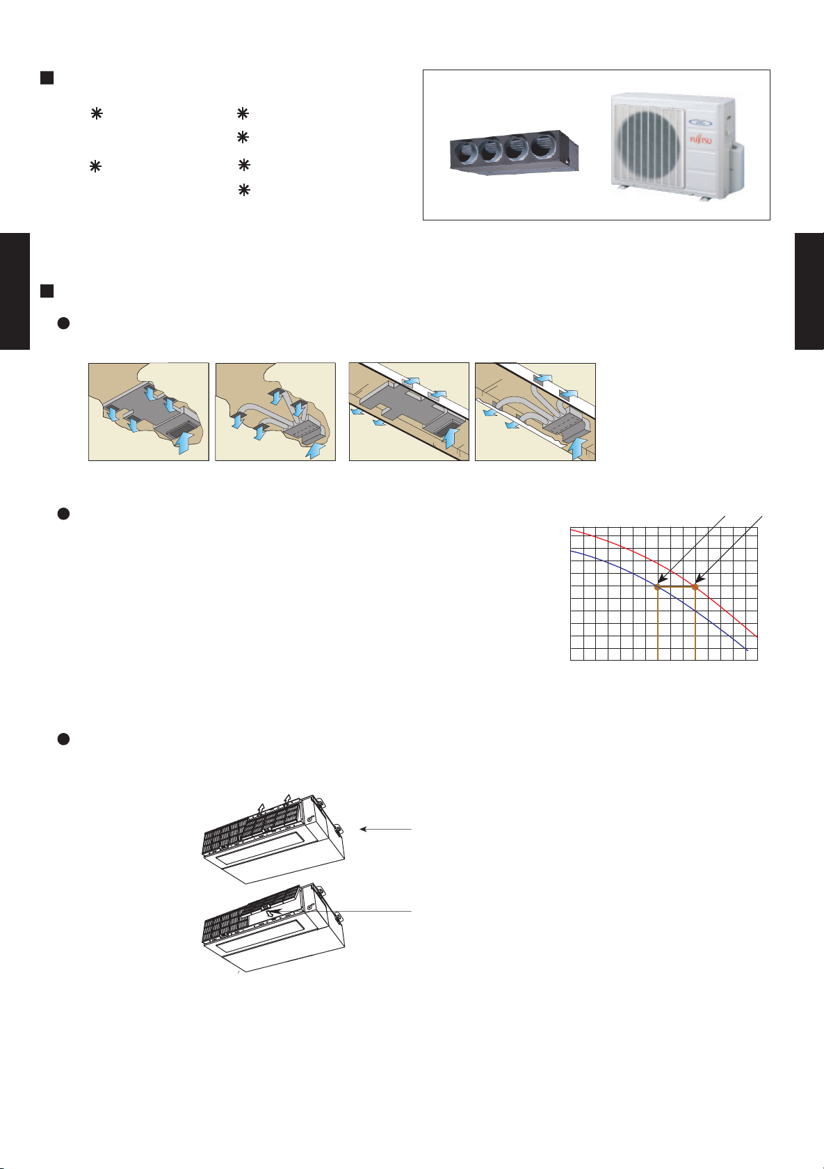
FEATURES
Installation styles
DUCT TYPE
AR25
Embedded in Ceiling
Hanging from Ceiling
DUCT TYPE
AR25
Low static pressure mode function
1.Low static pressure mode 1 air volume at 70Pa (fan speed:high)
2.Normal Mode Air volume at 100Pa (fan speed:high)
When installed, normal middle static pressure mode, and low static
pressure mode can be selected by switching over using DIP switch
on the board in the control box. Therefore, these models can be operated under the wide range of conditions.
Slim & compact design
In the case of bottom suction type, as seen from lower rear part.
Control Box that has been convex shape
is now united with main unit (DIP Switch is
located on the internal substrate.)
One-touch operating and easy-to-install
long-life filter (optional)
(230V)
/h)
3
Air volume (m
0 70 100
Static pressure (Pa)
1 2
In addition to the slim height of 270 mm which is our sales point, further compactification is attained by reducing 65 mm from the width with the flanking
control box embedded inside the chassis.
- (03 - 01) -
Page 3

EASY MAINTENANCE
In the case of rear suction type, as seen from lower rear part.
Conventional model
1
3
4
New model
4
1
1.Control box
2.Fan casing
3.Fan
4.Motor
2
2
DUCT TYPE
AR25
3
Bottom panel: 2 units
DUCT TYPE
AR25
Large bottom panel: 1 unit
Structural improvement is attained by making the bottom panel two pieces, front and
rear, and the internal fan casing is also made dismountable in two pieces namely,
upper and lower ones.
The motor and fan maintenance and dismounting can be made easily by removing
the rear panel and lower part of the casing with the main chassis installed.
- (03 - 02) -
Page 4
3-2. REMOTE CONTROLLER
3-2-1. WIRED REMOTE CONTROLLER
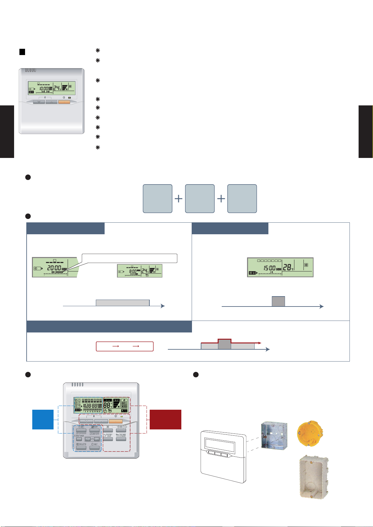
FEATURES
Various timer setup (ON / OFF / WEEKLY) are possible.
Equipped with weekly timer as standard function.
(2 times Start / Stop per day for a week)
SUMOTUWETH FR SA
7
3126 9
15 18 21
When setting up a timer, operation mode and a temperature
setup can be changed.
When a failure occurs,the error code is displayed. (Maximum of 16)
Error indication.(A maximum of 16 error histories are memorizable.)
Up to 16 indoor units can be simultaneously controlled.
Anti freeze and energy saving operation are possible.
Easy installation with a slim shape with no boldge in the back.
The room temperature can be controlled by being detected the temperature
DUCT TYPE
AR25
accurately with built-in thermo sensor.
DUCT TYPE
AR25
High performance and compact size
Three functions are combined in
one unit.
Wired
remote
controller
Weekly
timer
Setback
timer
Built-in timers
Setback timerWeekly timer
Possible to set ON/OFF time to operate twice each day
of the week.
SUMOTUWETH FR SA
7
3126 9
15 18 21
Setup screen example
(Set to Wednesday: 8:00 to 20:00.)
0 3 6 9 12 15 18 21 Time
Easy-to-understand time bar display
24°C
SUMOTUWETH FR SA
7
3126 9
15 1821
Screen
after setup
At "Weekly timer" + "Set back timer" setup
24°C 28°C 24°C
0 3 6 9 12 15 18 21 Time
Timer
area
Operation
area
Possible to set temperature for two time spans and
for each day of the week.
SUMOTUWETH FR SA
3126 9
15 18 21
Setup screen example
(Set from Sunday to Saturday: 12:00 to 15:00, 28 °C.)
28°C
0 3 6 9 12 15 18 21 Time
24°C
28°C
Simple installationEasy-to-understand operation
Components are compatible with standard
switch boxes. Flat back construction allows
equipment to be installed wherever it is
needed.
[
Variable timer control
]
The operation/display sections are zoned according to time and operation, enabling variable programming to match application.
- (03 - 03) -
European
switch box
JIS box
Page 5
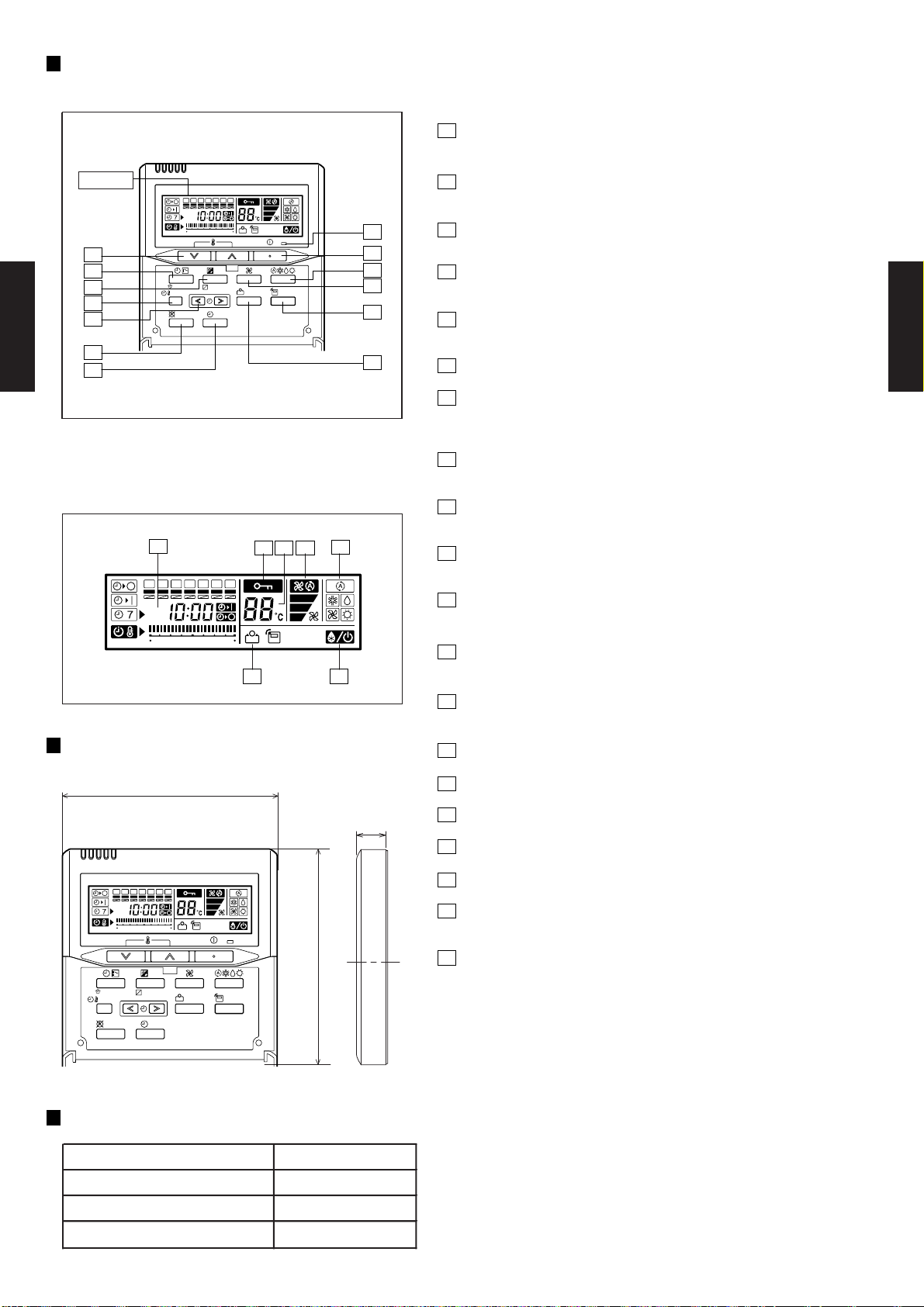
FUNCTIONS
1
START/STOP button
Pressed to start and stop operation.
Display
2
7
8
9
10
SUMOTUWETH FR
369
CLOCK ADJUST
SET BACK
DELETE SET
12 15 18 21
DAY
DAY OFF
SA
13
1
3
ENERGY
SAVE
THERMO
SENSOR
4
6
2
Set temperature button
Selects the setting temperature.
3
Master control button
Selects the operating mode(AUTO, HEAT, FAN, COOL, DRY).
4
Fan control button
Selects the fan speed (AUTO, LOW, MED, HIGH).
5
Energy save button
Turns the energy efficient mode on and off.
11
DUCT TYPE
AR25
12
5
6
Thermo sensor
7
Timer mode (CLOCK ADJUST) button
DUCT TYPE
AR25
Selects the timer mode (OFF TIMER, ON TIMER, WEEKLY TIMER)
Set the current time.
8
Day (DAY OFF) button
Display panel
Temporarily cancels of one day timer.
9
Set back button
pressed select the set back timer.
14
15
1617 18
10
Set time button
Pessed to select the set back timer.
SUMOTUWETH FR
SA
11
Delete button
The schedule of a weekly timer is deleted.
369
12 15 18 21
1920
12
Set button
Sets the date, hour, minute and on-off time.
13
Operation lamp
Lights during operation and when the timer is on.
DIMENSION
[ Unit : mm ]
17
120
SUMOTUWETH FR
369
12 15 18 21
DAY
CLOCK ADJUST
DAY OFF
SET BACK
DELETE SET
Front View
120
SA
ENERGY
SAVE
THERMO
SENSOR
SPECIFICATION
SIZE (H x W x D mm) 120 x 120 x 17
WEIGHT ( g ) 160
CABLE LENGTH ( m )
POWER ( V )
10
12
14
Timer and clock display
15
Operation mode display
16
Fan speed display
17
Central control display
18
Temperature display
19
Stand by display
Indicates during the oil recovery and defrosting operation.
20
Energy save display
- (03 - 04) -
Page 6
3-3. SPECIFICATIONS
COOLING TYPE
AR 25FUAN AR 25UUAN ART25UUAN
AO 25FNAKL AO 25UNAKL AOT 25UNAKL
240V 50Hz
D D -
kW 7.05 7.00 7.10
BTU/h 24000 24000 24200
kW - 7.70 7.70
BTU/h - 26,300 26,300
COOLING RATED 2.60 2.65 2.65
HEATING RATED - 2.33 2.38
COOLING RATED 11.5 11.8 11.8
HEATING RATED - 10.5 10.5
A 35
EER COOLING 2.71 2.64 2.68
COP HEATING - 3.30 3.24
l/h
High 1180
Med 1090
Low 1000
QUIET -
High 3200
Low -
High 1210
Med 1140
Low 1050
QUIET -
High 780
Low 400
Pa
INDOOR
OUTDOOR
INDOOR
OUTDOOR
High 38/ - 38/38 39/39
Med 36/ - 36/36 37/37
Low 34/ - 34/34 35/35
53 / - 53 / 54 53 / 54
OUTPUT W
Rows x Stages x
Fin Pitch
mm
Coil Dimensions mm
Rows x Stages x
Fin Pitch
mm
Coil Dimensions mm
INDOOR
OUTDOOR
INDOOR
OUTDOOR
INDOOR
OUTDOOR
INDOOR
OUTDOOR 58 / 62 (128 / 137)
LIQUID
GAS
m
m
CHARGE g 1550
COOLING
HEATING
mm
Note: Specifications are based on the following conditions.
Cooling: Indoor temperature of 27 °CDB / 19 °CWB,and outdoor temperature of 35 °CDB/24 °CWB.
Heating: Indoor temperature of 20 °CDB / 15 °CWB,and outdoor temperature of 7 °CDB/6 °CWB.
Standard static pressure : 100 Pa.
Pipe length : 7.5 m, Height difference : 0 m.(Outdoor unit - Indoor unit)
INDOOR
OUTDOOR
TYPE
270 × 1135 × 700
650 × 830 × 320
630 × 901 × 36.38
Galvanized steel sheet
Beige(10YR7.5/1.0NN)
300 × 1300 × 790
768 x 984 x 413
Synthetic (POE oil)
0 to 43
FLARE
9.52(3/8 inc.)
15.88(5/8 inc.)
25 (chargeless:7.5m)
15
R410A
2.5(5.3)
Copper tube
Alminume fin
ROTARY
Propeller x 1
70
65
Permanent Starting Condenser
1900
1200
294 × 1000 × 39.9
Alminume fin
2 x 30 x 1.45
Copper tube
3 x 14 x 1.40
DIMENSIONS
H ×W ×D
REMOTE CONTROLLER
TYPE
REFRIGERANT OIL
PIPE
SIZE
mm
MAX HEIGHT
MAX LENGTH
Fin
NOISE LEVEL
(SOUND
PRESSURE)
COOL/HEAT
OUTDOOR
OUTDOOR
Coil
INDOOR
Coil
60
-7 to 24
Fin
dB(A)
STARTING CURRENT
COMPRESSOR
STARTING METHOD
INDOOR
TYPE
CONNECTION METHOD
WIRED(3TA)
230V 50Hz
900
3200
30 to 150
Sirocco x 2
1100
1000
43 / 50 ( 95 / 110)
59 / 63 (130 / 139)
DUCTED MODELS
MODEL NAME
A
kW
AVAILABLE VOLTAGE RANGE
EUROPEAN ENERGY LABEL
198-264V 50Hz
HEAT PUMP TYPE
POWER SOURCE
CURRENT
RATED
MOISTURE REMOVAL
OUTDOOR
INPUT POWER
COOLING
HEATING
RATED
CAPACITY
kW/kW
RECOMMENDED STATIC PRESSURE
FAN TYPE x Q'ty
INDOOR
AIR
CIRCULATION
FAN MOTOR OUTPUT
W
WEIGHT
NET
GROSS
CASING COLOR
mm
kg(lbs)
NET /
GROSS
HEAT
EXCHANGER
TYPE
2000
DRAIN PIPE
MATERIAL
SIZE
Steel
Outer diameter 38mm / Inner diameter 36mm
OPERATION(OUTDOOR)
°C
REFRIGERANT
TYPE
m3/h
FAN SPEED
INDOOR
OUTDOOR
r.p.m
---
400
1120
1030
780
DUCT TYPE
AR25
DUCT TYPE
AR25
- (03 - 05) -
Page 7
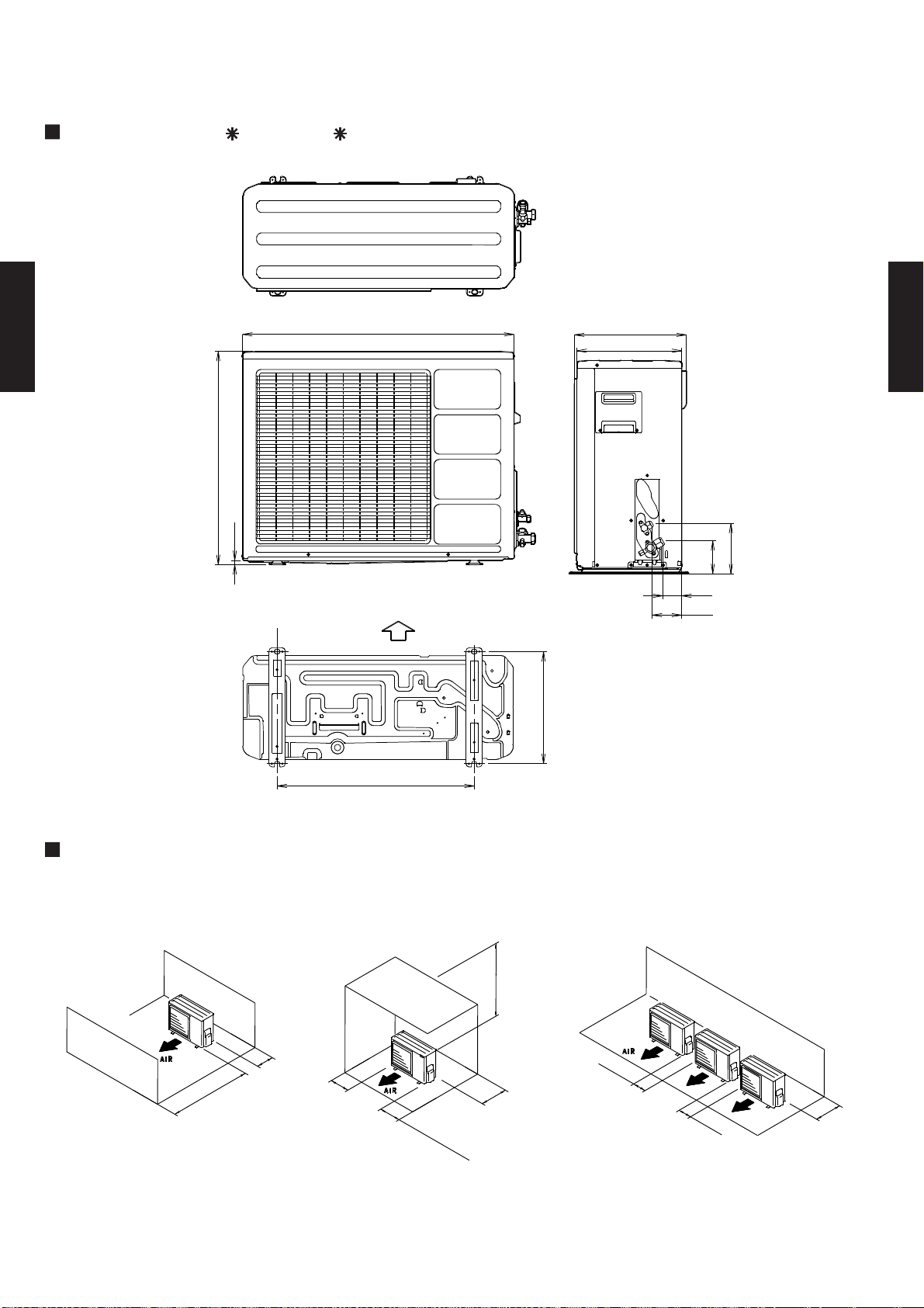
3-4. DIMENSIONS
3-4-1. OUTDOOR UNIT
MODELS : AO 25F, AO 25U, AOT25U
(Unit : mm)
Top view
830
DUCT TYPE
AR25
650
12
Front view
Bottom
Air flow
350
320
Side view
DUCT TYPE
AR25
154
101
58
90
MOUNTING POSITION
When there are obstacles at the
back or front sides.
100 mm
or more
100 mm
600 mm
or more
or more
603
Bottom view
When there are obstacles at the
back, side(s), and top.
600 mm or more
300 mm
250 mm
(Se
r
v
o
ice
r
m
spa
ore
c
e)
or more
343
When there are obstacles at the
back, side with the installation of
more than one unit.
250 mm
or more
250 mm
or more
300 mm
or more
- (03 - 06) -
Page 8
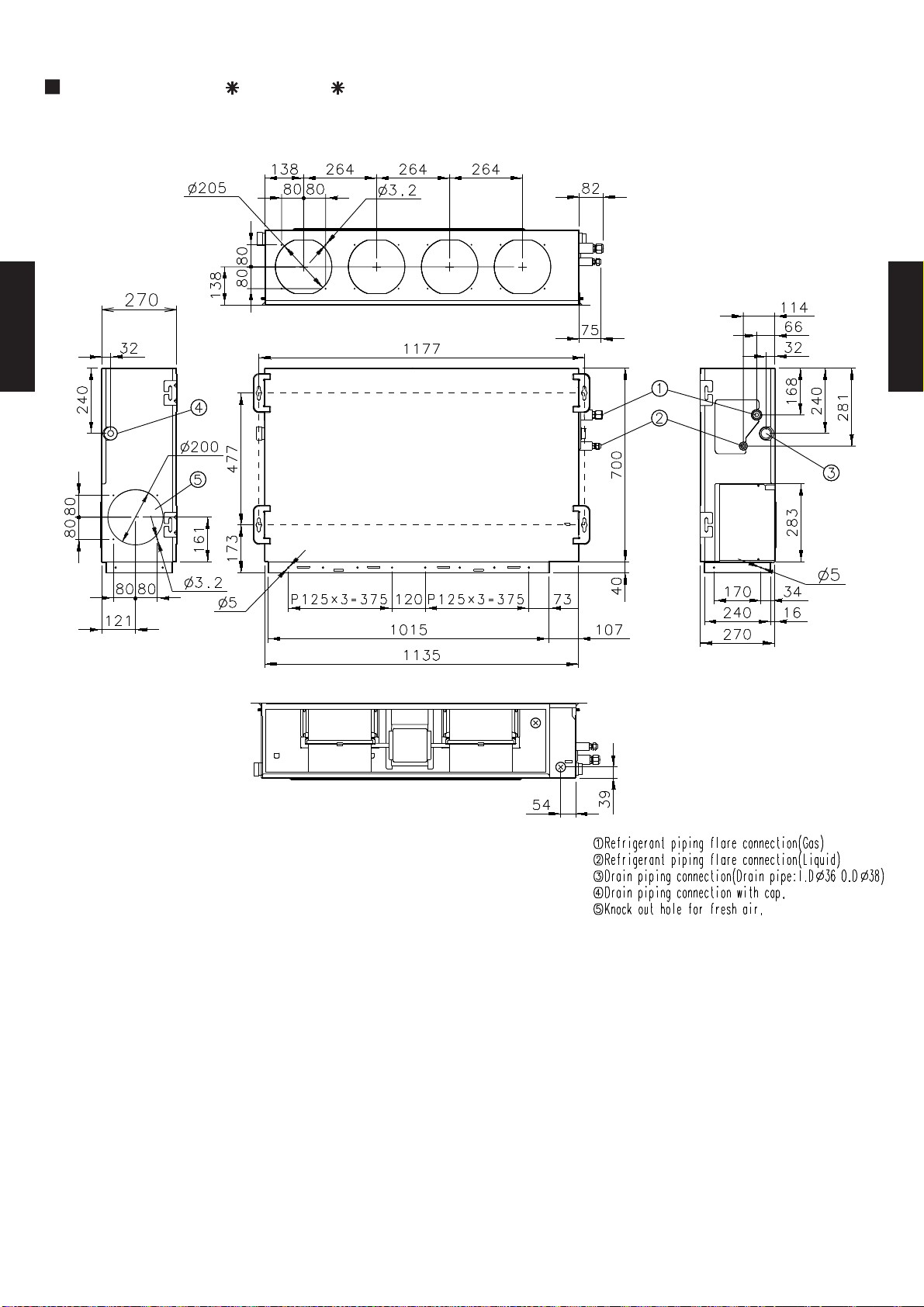
3-4-2. INDOOR UNIT
MODELS : AR 25F, AR 25U, ART25U
DUCT TYPE
AR25
Front view
(Unit : mm)
DUCT TYPE
AR25
Side view (L)
Side view (R)
Top view
Rear view
- (03 - 07) -
Page 9
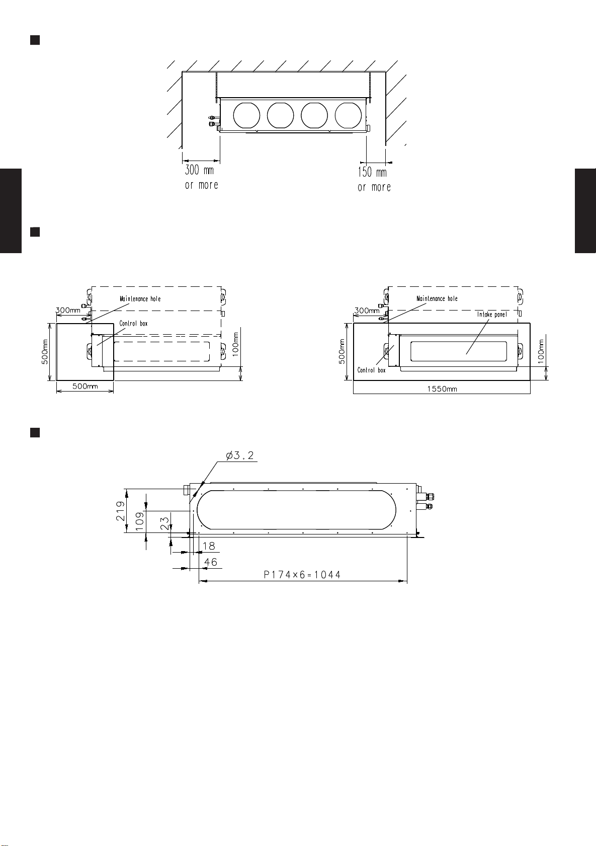
MOUNTING POSITION
MAINTENANCE HOLE
DUCT TYPE
AR25
It shall be possible to install and remove
the control box.
It shall be possible to install and remove
the control box, fan units and filter.
DUCT TYPE
AR25
WHEN USING A SQUARE DUCT
- (03 - 08) -
Page 10
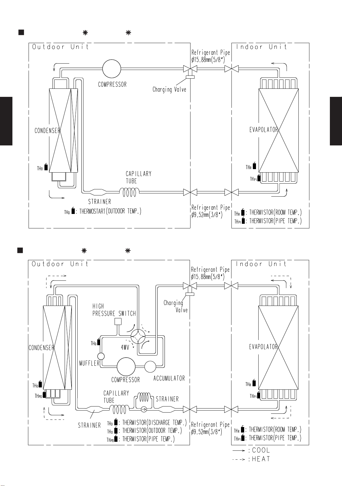
3-5. REFRIGERANT CIRCUIT
MODELS : AR 25F / AO 25F
DUCT TYPE
AR25
DUCT TYPE
AR25
MODELS : AR 25U / AO 25U , ART25U / AOT25U
- (03 - 09) -
Page 11
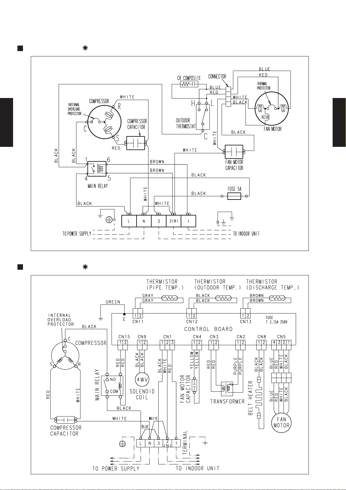
3-6. WIRING DIAGRAMS
3-6-1. OUTDOOR UNIT
MODEL : AO 25F
DUCT TYPE
AR25
DUCT TYPE
AR25
MODEL : AO 25U
- (03 - 10) -
Page 12
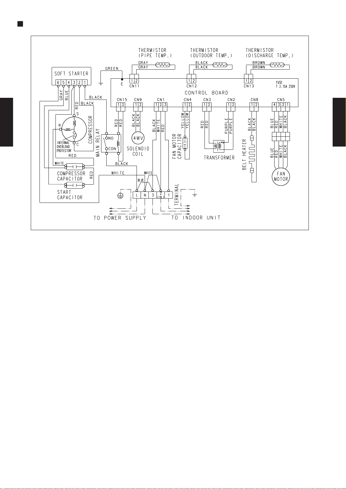
MODEL : AOT25U
DUCT TYPE
AR25
DUCT TYPE
AR25
- (03 - 11) -
Page 13
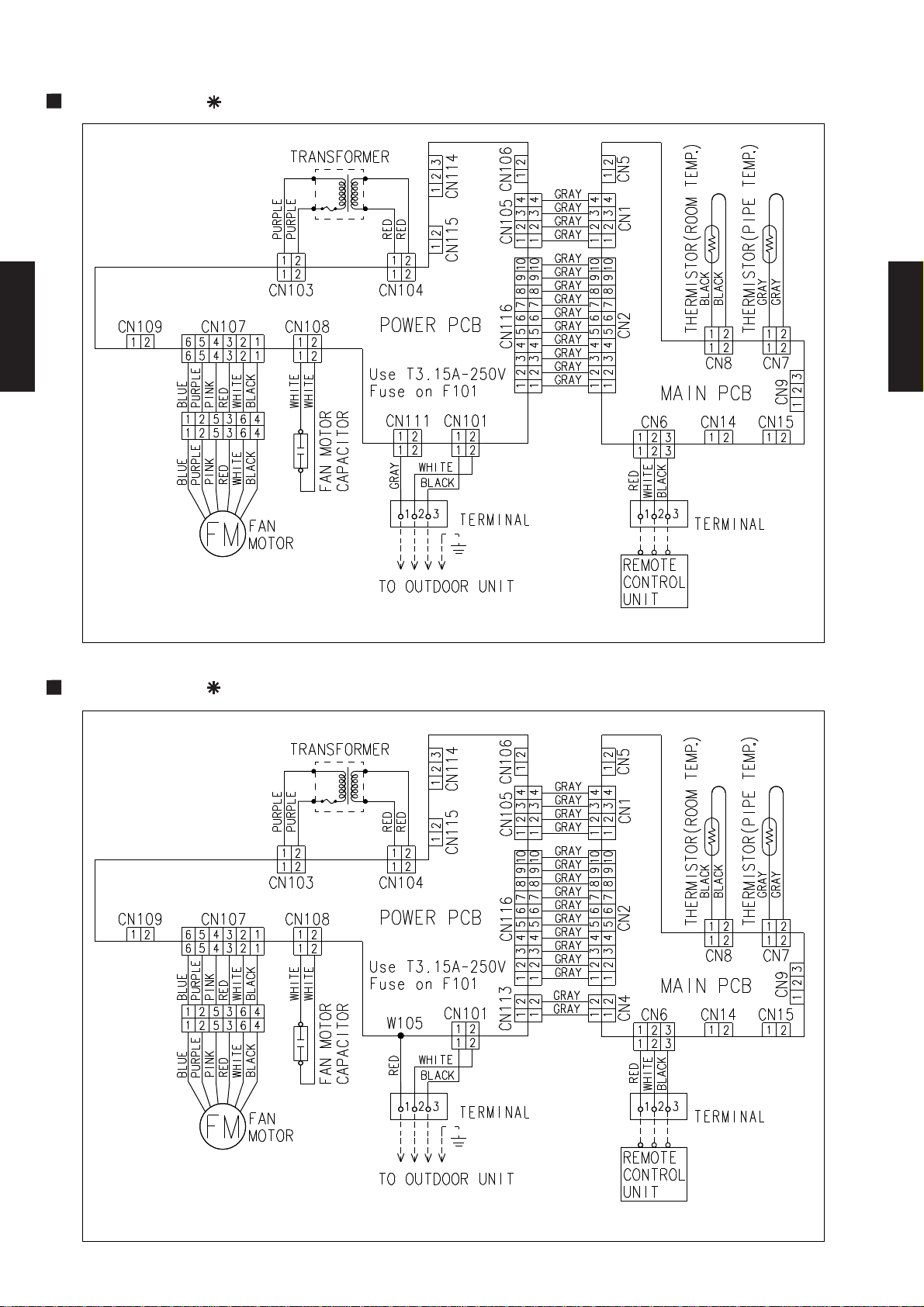
3-6-2. INDOOR UNIT
MODEL : AR 25F
DUCT TYPE
AR25
DUCT TYPE
AR25
MODEL : AR 25U
- (03 - 12) -
Page 14

MODEL : ART25U
DUCT TYPE
AR25
DUCT TYPE
AR25
- (03 - 13) -
Page 15

AFR
AFR
3-7. CAPACITY TABLE
AFR
Outdoor temperature
Indoor temperature
12°CWB
15°CWB
16°CWB
18°CWB
19°CWB
21°CWB
22°CWB
19°CWB
21°CWB
22°CWB
23°CWB
12°CWB
15°CWB
16°CWB
18°CWB
Indoor temperature
18°CDB
21°CDB
23°CDB
26°CDB
27°CDB
29°CDB
30°CDB
32°CDB
23°CWB
Outdoor temperature
27°CDB
29°CDB
30°CDB
32°CDB
18°CDB
21°CDB
23°CDB
26°CDB
Outdoor temperature
18°CDB
12°CWB
15°CWB
26°CDB
21°CDB
Indoor temperature
32°CDB
30°CDB
23°CDB
27°CDB
29°CDB
23°CWB
22°CWB
16°CWB
18°CWB
19°CWB
21°CWB
3-7-1. COOLING
MODELS : AR 25F / AO 25F
18.3
(°CDB) TC SHC PI TC SHC PI TC SHC PI TC SHC PI TC SHC PI TC SHC PI TC SHC PI TC SHC PI
0 8.05 6.02 1.63 8.21 6.05 1.67 8.37 6.07 1.69 8.61 6.33 1.71 8.71 6.28 1.72 8.89 6.17 1.74 8.98 6.11 1.75 9.06 6.36 1.76
5 7.76 5.86 1.83 7.94 5.89 1.87 8.13 5.91 1.89 8.42 6.21 1.92 8.54 6.18 1.93 8.75 6.09 1.96 8.84 6.04 1.97 8.93 6.30 1.99
10 7.43 5.66 2.02 7.62 5.68 2.06 7.80 5.72 2.09 8.12 6.05 2.13 8.24 6.02 2.14 8.46 5.95 2.18 8.56 5.91 2.19 8.66 6.18 2.21
15 7.08 5.46 2.21 7.25 5.49 2.26 7.44 5.53 2.29 7.73 5.86 2.33 7.86 5.84 2.35 8.08 5.78 2.39 8.18 5.75 2.41 8.28 6.02 2.43
20 7.06 5.28 2.43 7.21 5.30 2.47 7.38 5.33 2.49 7.67 5.65 2.54 7.79 5.63 2.56 8.02 5.58 2.61 8.12 5.56 2.63 8.22 5.84 2.65
25 7.34 5.44 2.10 7.52 5.46 2.13 7.69 5.50 2.14 7.98 5.80 2.17 8.10 5.78 2.19 8.32 5.72 2.22 8.42 5.68 2.23 8.52 5.96 2.24
DUCT TYPE
30 6.87 5.19 2.31 7.07 5.22 2.32 7.23 5.28 2.34 7.50 5.59 2.38 7.62 5.57 2.39 7.84 5.52 2.43 7.95 5.50 2.44 8.05 5.78 2.45
AR25
35 6.39 4.97 2.51 6.51 5.01 2.52 6.68 5.04 2.54 6.93 5.34 2.58 7.05 5.33 2.60 7.28 5.30 2.63 7.38 5.28 2.65 7.49 5.57 2.67
40 5.82 4.72 2.73 5.90 4.74 2.73 6.04 4.76 2.75 6.29 5.07 2.79 6.41 5.07 2.81 6.63 5.04 2.85 6.74 5.03 2.87 6.84 5.33 2.91
43 5.41 4.51 2.85 5.50 4.56 2.86 5.63 4.58 2.88 5.87 4.90 2.92 5.99 4.89 2.94 6.21 4.88 2.98 6.33 4.88 3.00 6.45 5.19 3.02
MODELS : AR 25U / AO 25U
DUCT TYPE
AR25
18.3
(°CDB) TC SHC PI TC SHC PI TC SHC PI TC SHC PI TC SHC PI TC SHC PI TC SHC PI TC SHC PI
0 7.99 5.97 1.66 8.15 5.99 1.71 8.31 6.02 1.72 8.55 6.27 1.74 8.65 6.22 1.76 8.83 6.11 1.78 8.91 6.05 1.79 8.99 6.30 1.80
5 7.71 5.81 1.87 7.88 5.83 1.90 8.08 5.85 1.92 8.36 6.15 1.96 8.48 6.12 1.97 8.68 6.03 2.00 8.78 5.98 2.01 8.87 6.24 2.02
10 7.38 5.61 2.05 7.56 5.62 2.10 7.74 5.67 2.13 8.06 5.99 2.17 8.18 5.97 2.19 8.40 5.90 2.22 8.50 5.86 2.24 8.60 6.12 2.25
15 7.03 5.41 2.26 7.20 5.44 2.30 7.38 5.48 2.33 7.68 5.80 2.38 7.80 5.78 2.40 8.02 5.73 2.44 8.12 5.70 2.46 8.22 5.97 2.48
20 7.01 5.23 2.47 7.16 5.25 2.51 7.33 5.28 2.54 7.61 5.60 2.59 7.73 5.58 2.61 7.96 5.53 2.66 8.06 5.50 2.68 8.16 5.78 2.70
25 7.28 5.39 2.14 7.47 5.41 2.17 7.64 5.44 2.18 7.92 5.75 2.22 8.04 5.73 2.23 8.26 5.66 2.26 8.36 5.63 2.27 8.45 5.90 2.29
30 6.82 5.14 2.35 7.02 5.17 2.37 7.18 5.23 2.39 7.45 5.54 2.42 7.57 5.52 2.44 7.79 5.47 2.47 7.89 5.45 2.49 8.00 5.73 2.50
35 6.35 4.93 2.56 6.46 4.96 2.57 6.63 4.99 2.59 6.88 5.29 2.63 7.00 5.28 2.65 7.22 5.25 2.69 7.33 5.23 2.70 7.44 5.52 2.72
40 5.77 4.67 2.78 5.86 4.70 2.79 6.00 4.72 2.80 6.24 5.02 2.85 6.36 5.02 2.87 6.58 4.99 2.91 6.69 4.98 2.93 6.80 5.28 2.97
43 5.37 4.46 2.90 5.46 4.51 2.91 5.59 4.54 2.93 5.83 4.85 2.97 5.95 4.85 2.99 6.17 4.84 3.04 6.29 4.83 3.06 6.40 5.14 3.08
MODELS : ART25U / AOT25U
19.3
(°CDB) TC SHC PI TC SHC PI TC SHC PI TC SHC PI TC SHC PI TC SHC PI TC SHC PI TC SHC PI
0 8.11 6.08 1.66 8.26 6.11 1.71 8.42 6.13 1.72 8.67 6.39 1.74 8.77 6.34 1.76 8.96 6.23 1.78 9.04 6.17 1.79 9.12 6.42 1.80
5 7.82 5.92 1.87 8.00 5.95 1.90 8.19 5.96 1.92 8.48 6.27 1.96 8.60 6.23 1.97 8.81 6.15 2.00 8.90 6.10 2.01 9.00 6.36 2.02
10 7.48 5.71 2.05 7.67 5.73 2.10 7.86 5.77 2.13 8.17 6.10 2.17 8.30 6.08 2.19 8.52 6.01 2.22 8.62 5.97 2.24 8.72 6.24 2.25
15 7.13 5.51 2.26 7.30 5.54 2.30 7.49 5.58 2.33 7.79 5.91 2.38 7.91 5.89 2.40 8.14 5.84 2.44 8.24 5.80 2.46 8.34 6.08 2.48
20 7.11 5.33 2.47 7.26 5.35 2.51 7.44 5.38 2.54 7.72 5.70 2.59 7.84 5.69 2.61 8.07 5.64 2.66 8.18 5.61 2.68 8.28 5.89 2.70
25 7.39 5.49 2.14 7.57 5.52 2.17 7.75 5.55 2.18 8.03 5.86 2.22 8.16 5.83 2.23 8.38 5.77 2.26 8.48 5.74 2.27 8.58 6.01 2.29
30 6.92 5.24 2.35 7.12 5.27 2.37 7.28 5.33 2.39 7.55 5.64 2.42 7.67 5.62 2.44 7.90 5.57 2.47 8.01 5.55 2.49 8.11 5.83 2.50
35 6.44 5.02 2.56 6.56 5.06 2.57 6.73 5.09 2.59 6.98 5.39 2.63 7.10 5.38 2.65 7.33 5.35 2.69 7.44 5.33 2.70 7.55 5.62 2.72
40 5.86 4.76 2.78 5.94 4.79 2.79 6.08 4.81 2.80 6.33 5.12 2.85 6.45 5.11 2.87 6.67 5.09 2.91 6.78 5.08 2.93 6.89 5.38 2.97
43 5.44 4.55 2.90 5.54 4.60 2.91 5.67 4.62 2.93 5.91 4.94 2.97 6.03 4.94 2.99 6.25 4.93 3.04 6.38 4.93 3.06 6.49 5.23 3.08
AFR: Air flow rate (m3/min)
TC : Total capacity (kW)
SHC: Sensible Heat capacity (kW)
PI : Power Input (kW)
- (03 - 14) -
Page 16

3-7-2. HEATING
AFR
AFR
Outdoor temperature
16°CDB
18°CDB
Outdoor temperature
Indoor temperature
16°CDB
18°CDB
20 °CDB
23°CDB
30°CDB
27°CDB
27°CDB
30°CDB
Indoor temperature
25°CDB
25°CDB
23°CDB
20°CDB
MODELS : AR 25U / AO 25U
18.3
(°CDB) (°CDB) TC PI TC PI TC PI TC PI TC PI TC PI TC PI
-7 -9 5.01 1.76 4.93 1.82 4.77 1.87 4.62 1.93 4.54 1.96 4.39 2.01 4.24 2.04
-4 -6 5.47 1.90 5.39 1.96 5.24 2.01 5.08 2.07 5.01 2.10 4.85 2.15 4.70 2.18
1 -1 6.16 2.15 6.08 2.21 5.93 2.26 5.78 2.32 5.70 2.35 5.54 2.40 5.39 2.43
5 3 7.55 2.21 7.47 2.26 7.32 2.31 7.16 2.35 7.08 2.38 6.93 2.42 6.78 2.45
7 6 7.93 2.24 7.85 2.28 7.70 2.33 7.55 2.38 7.47 2.40 7.32 2.45 7.16 2.47
12 10 8.47 2.40 8.39 2.45 8.24 2.49 8.09 2.54 8.01 2.56 7.85 2.61 7.70 2.63
15 13 8.55 2.49 8.47 2.54 8.32 2.59 8.16 2.63 8.09 2.66 7.93 2.70 7.78 2.73
20 15 7.93 2.24 7.85 2.28 7.70 2.33 7.55 2.38 7.47 2.40 7.32 2.45 7.16 2.47
24 17 7.47 2.10 7.39 2.14 7.24 2.19 7.08 2.24 7.01 2.26 6.85 2.31 6.70 2.33
DUCT TYPE
AR25
MODELS : ART25U / AOT25U
19.3
DUCT TYPE
AR25
(°CDB) (°CDB) TC PI TC PI TC PI TC PI TC PI TC PI TC PI
-7 -9 5.01 1.80 4.93 1.86 4.77 1.91 4.62 1.97 4.54 2.00 4.39 2.06 4.24 2.08
-4 -6 5.47 1.94 5.39 2.00 5.24 2.06 5.08 2.11 5.01 2.14 4.85 2.20 4.70 2.23
1 -1 6.16 2.20 6.08 2.26 5.93 2.31 5.78 2.37 5.70 2.40 5.54 2.46 5.39 2.48
5 3 7.55 2.26 7.47 2.31 7.32 2.35 7.16 2.40 7.08 2.43 6.93 2.48 6.78 2.50
7 6 7.93 2.28 7.85 2.33 7.70 2.38 7.55 2.43 7.47 2.45 7.32 2.50 7.16 2.52
12 10 8.47 2.45 8.39 2.50 8.24 2.55 8.09 2.59 8.01 2.62 7.85 2.67 7.70 2.69
15 13 8.55 2.55 8.47 2.59 8.32 2.64 8.16 2.69 8.09 2.71 7.93 2.76 7.78 2.78
20 15 7.93 2.28 7.85 2.33 7.70 2.38 7.55 2.43 7.47 2.45 7.32 2.50 7.16 2.52
24 17 7.47 2.14 7.39 2.19 7.24 2.24 7.08 2.28 7.01 2.31 6.85 2.36 6.70 2.38
AFR: Air flow rate (m3/min)
TC : Total capacity (kW)
SHC: Sensible Heat capacity (kW)
PI : Power Input (kW)
- (03 - 15) -
Page 17

3-8.
PIPE LENGTH (m)
COOLING
HEIGHT DIFFERENCE (m)
Outdoor unit
is up-side
Outdoor unit is
bottom-side
HEIGHT DIFFERENCE (m)
Outdoor unit is
bottom-side
Outdoor unit
is up-side
HEATING
PIPE LENGTH (m)
HEIGHT DIFFERENCE (m)
Outdoor unit is
bottom-side
Outdoor unit
is up-side
COOLING
PIPE LENGTH (m)
CAPACITY COMPENSATION FOR PIPE LENGTH
AND HEIGHT DIFFERENCE
MODELS : AR 25F / AO 25F
5 7.5 10 15 20 25
15 - - - 0.952 0.919 0.888
10 - - 0.985 0.952 0.919 0.888
7.5 - 1.000 0.985 0.952 0.919 0.888
5 1.010 1.000 0.985 0.952 0.919 0.888
0 1.010 1.000 0.985 0.952 0.919 0.888
-5 1.002 0.992 0.977 0.944 0.912 0.881
DUCT TYPE
AR25
-7.5 - 0.988 0.973 0.941 0.908 0.877
-10 - - 0.969 0.937 0.904 0.874
-15 - - - 0.929 0.897 0.867
DUCT TYPE
AR25
MODELS : AR 25U / AO 25U, ART25U / AOT25U
5 7.5 10 15 20 25
15 - - - 0.952 0.919 0.888
10 - - 0.985 0.952 0.919 0.888
7.5 - 1.000 0.985 0.952 0.919 0.888
5 1.010 1.000 0.985 0.952 0.919 0.888
0 1.010 1.000 0.985 0.952 0.919 0.888
-5 1.002 0.992 0.977 0.944 0.912 0.881
-7.5 - 0.988 0.973 0.941 0.908 0.877
-10 - - 0.969 0.937 0.904 0.874
-15 - - - 0.929 0.897 0.867
5 7.5 10 15 20 25
15 - - - 0.956 0.939 0.922
10 - - 0.979 0.961 0.943 0.927
7.5 - 0.993 0.982 0.964 0.946 0.929
5 1.005 0.995 0.984 0.966 0.948 0.931
0 1.010 1.000 0.989 0.971 0.953 0.936
-5 1.010 1.000 0.989 0.971 0.953 0.936
-7.5 - 1.000 0.989 0.971 0.953 0.936
-10 - - 0.989 0.971 0.953 0.936
-15 - - - 0.971 0.953 0.936
- (03 - 16) -
Page 18

3-9. ADDITIONAL CHARGE CALCULATION
COOLING TYPE HEAT PUMP TYPE
AR 25F
AR 25U
AO 25F
AO 25U
AOT25U
m 7.5 7.5
1550 2000
1550+50 2000+100
1550+150 2000+300
1550+250 2000+500
1550+350 2000+700
20 40
PRECHARGE
R410A
TYPE
DUCTED MODEL
MODEL NAME
MODELS : AR 25F / AO 25F , AR 25U / AO 25U
ART25U / AOT25U
REFRIGERANT CHARGE
INDOOR
OUTDOOR
DUCT TYPE
AR25
DUCT TYPE
AR25
ADDITIONAL
charge
REFREGERANT TYPE
CHARGELESS PIPE LENGTH
AMOUNT
10m
15m
20m
25m (max)
g/m
g
ART25U
DUCT TYPE
AR25
DUCT TYPE
AR25
- (03 - 17) -
Page 19

3-10. OPERATION RANGE
Cooling
Dry
80 % or less 0 to 43 °C
Cooling
Dry
80 % or less 0 to 43 °C
Heating 16 to 30 °C - -7 to 24 °C
Model
Operation Range
Mode
Model
Operation Range
AR 25U
AO 25U
Mode
Indoor unit Outdoor unit Indoor unit Indoor humidity Outdoor unit
AR 25F AO 25F
18 to 32 °C
Indoor unit Outdoor unit Indoor unit Indoor humidity Outdoor unit
18 to 32 °C
ART25U AOT25U
DUCT TYPE
AR25
DUCT TYPE
AR25
- (03 - 18) -
Page 20

3-11. FAN PERFORMANCE AND AIR FLOW
30 50 80 100 120 140 150
m3/h
1440 1360 1220 1100 970 780 670
l/s 400 378 339 306 269 217 186
CFM 848 800 718 647 571 459 394
m3/h
1270 1190 1060 950 830 650 -
l/s 353 331 294 264 231 181 -
CFM 747 700 624 559 489 383 -
m3/h
1120 1050 920 820 700 - -
l/s 311 292 256 228 194 - -
CFM 659 618 541 483 412 - -
FAN SPEED
Hi
Med
Low
230V
Static pressure (Pa)
3-11-1. NORMAL MODE
MODELS : AR 25F / AO 25F
230V
DUCT TYPE
AR25
Q-h Characteris tic curve
160
140
120
Hi
Med
Low
DUCT TYPE
AR25
100
80
60
40
20
0
500 1000 1500
COOLING
110.0
Air temp
Capacity
100.0
90.0
Cooling capacity(%) STATIC PRESSURE(Pa)
80.0
500 1,000 1,500
AIR FLOW (m3/h)
16.0
15.0
14.0
13.0
12.0
11.0
10.0
°C)
Air temperature(
Testcondition:NofilterandFanmode.
- (03 - 19) -
Page 21

MODELS : AR 25U / AO 25U
30 50 80 100 120 140 150
m3/h
1440 1360 1220 1100 970 780 670
l/s 400 378 339 306 269 217 186
CFM 848 800 718 647 571 459 394
m3/h
1270 1190 1060 950 830 650 -
l/s 353 331 294 264 231 181 -
CFM 747 700 624 559 489 383 -
m3/h
1120 1050 920 820 700 - -
l/s 311 292 256 228 194 - -
CFM 659 618 541 483 412 - -
FAN SPEED
Hi
Med
Low
230V
Static pressure (Pa)
230V
DUCT TYPE
AR25
160
140
120
100
Q-h Characteris tic curve
Hi
Med
Low
DUCT TYPE
AR25
80
60
40
20
0
500 1000 1500
COOLING
110.0
Air temp
Capacity
100.0
90.0
Cooling capacity(%) STATIC PRESSURE(Pa)
80.0
500 1,000 1,500
HEATING
Air temp
105.0
100.0
95.0
Heating capacity(%)
90.0
500 1,000 1,500
Capacity
16.0
15.0
14.0
13.0
12.0
11.0
10.0
52.0
50.0
48.0
46.0
44.0
42.0
40.0
38.0
36.0
34.0
°C)
Air temperature(
°C)
Air temperature(
Testcondition:NofilterandFanmode.
AIR FLOW (m3/h)
- (03 - 20) -
Page 22

MODELS : ART25U / AOT25U
30 50 80 100 120 140 150
m3/h
1500 1420 1280 1160 1030 840 730
l/s 417 394 356 322 286 233 203
CFM 883 836 753 683 606 494 430
m3/h
1330 1250 1120 1010 890 710 -
l/s 369 347 311 281 247 197 -
CFM 783 736 659 594 524 418 -
m3/h
1180 1110 980 880 760 - -
l/s 328 308 272 244 211 - -
CFM 695 653 577 518 447 - -
Static pressure (Pa)
240V
FAN SPEED
Hi
Med
Low
240V
DUCT TYPE
AR25
Q-h Characteris tic curve
160
140
120
100
Hi
Med
Low
DUCT TYPE
AR25
80
60
40
20
0
600 1,100 1,600
COOLING
110.0
Air temp
Capacity
100.0
90.0
Cooling capacity(%) STATIC PRESSURE(Pa)
80.0
600 1,100 1,600
HEATING
Air temp
105.0
100.0
95.0
Heating capacity(%)
90.0
600 1,100 1,600
Capacity
16.0
15.0
14.0
13.0
12.0
11.0
10.0
52.0
50.0
48.0
46.0
44.0
42.0
40.0
38.0
36.0
34.0
°C)
Air temperature(
°C)
Air temperature(
Testcondition:NofilterandFanmode.
AIR FLOW (m3/h)
- (03 - 21) -
Page 23

3-11-2. LOW STATIC PRESSURE MODE
30 50 80 100
m3/h
1270 1190 1060 950
l/s 353 331 294 264
CFM 747 700 624 559
m3/h
1120 1050 920 -
l/s 311 292 256 -
CFM 659 618 541 -
m3/h
980 930 - -
l/s 272 258 - -
CFM 577 547 - -
230V
Static pressure (Pa)
FAN SPEED
Hi
Med
Low
MODELS : AR 25F / AO 25F
230V
DUCT TYPE
AR25
Q-h Characteris tic curve
120
100
80
Hi
Med
Low
DUCT TYPE
AR25
60
40
20
0
500 1,000 1,500
COOLING
110.0
Air temp
Capacity
100.0
90.0
Cooling capacity(%) STATIC PRESSURE(Pa)
80.0
500 1,000 1,500
AIR FLOW (m3/h)
Testcondition:NofilterandFanmode.
16.0
15.0
14.0
13.0
12.0
11.0
10.0
°C)
Air temperature(
- (03 - 22) -
Page 24

MODELS : AR 25U / AO 25U
30 50 80 100
m3/h
1270 1190 1060 950
l/s 353 331 294 264
CFM 747 700 624 559
m3/h
1120 1050 920 -
l/s 311 292 256 -
CFM 659 618 541 -
m3/h
980 930 - -
l/s 272 258 - -
CFM 577 547 - -
230V
Static pressure (Pa)
FAN SPEED
Hi
Med
Low
230V
DUCT TYPE
AR25
Q-h Characteris tic curve
120
Hi
100
80
Med
Low
DUCT TYPE
AR25
60
40
20
0
500 1,000 1,500
COOLING
110.0
Air temp
Capacity
100.0
90.0
Cooling capacity(%) STATIC PRESSURE(Pa)
80.0
500 1,000 1,500
HEATING
Air temp
105.0
100.0
95.0
Heating capacity(%)
90.0
500 1,000 1,500
Capacity
16.0
15.0
14.0
13.0
12.0
11.0
10.0
52.0
50.0
48.0
46.0
44.0
42.0
40.0
38.0
36.0
34.0
°C)
Air temperature(
°C)
Air temperature(
Testcondition:NofilterandFanmode.
AIR FLOW (m3/h)
- (03 - 23) -
Page 25

MODEL : ART25U / AOT25U
30 50 80 100
m3/h
1330 1250 1120 1010
l/s 369 347 311 281
CFM 783 736 659 594
m3/h
1180 1110 980 -
l/s 328 308 272 -
CFM 695 653 577 -
m3/h
1080 1010 - -
l/s 300 281 - -
CFM 636 594 - -
240V
FAN SPEED
Hi
Med
Low
Static pressure (Pa)
240V
DUCT TYPE
AR25
Q-h Characteris tic curve
120
Hi
100
80
Med
Low
DUCT TYPE
AR25
60
40
20
0
500 1,000 1,500
COOLING
110.0
Air temp
Capacity
100.0
90.0
Cooling capacity(%) STATIC PRESSURE(Pa)
80.0
500 1,000 1,500
HEATING
Air temp
105.0
100.0
95.0
Heating capacity(%)
90.0
500 1,000 1,500
Capacity
16.0
15.0
14.0
13.0
12.0
11.0
10.0
52.0
50.0
48.0
46.0
44.0
42.0
40.0
38.0
36.0
34.0
°C)
Air temperature(
°C)
Air temperature(
Testcondition:NofilterandFanmode.
AIR FLOW (m3/h)
- (03 - 24) -
Page 26

3-12. NOISE LEVEL CURVE
3-12-1. COOLING
OUTDOOR UNIT
MODEL : AO 25F MODEL : AO 25U
Condition
Fan speed : High
Voltage : 230V /50Hz
Condition
Fan speed : High
Voltage : 230V /50Hz
80
70
60
DUCT TYPE
AR25
50
40
30
20
Octave band sound pressure level, dB:(0dB=0.0002µbar)
10
0
63
125
250
500
1000
Octave band center frequency,Hz
2000
N70
N60
N50
N40
N30
N20
4000
8000
80
70
60
50
40
30
20
Octave band sound pressure level, dB:(0dB=0.0002µbar)
10
0
63
125
250
500
1000
Octave band center frequency,Hz
2000
N70
N60
DUCT TYPE
N50
N40
N30
N20
4000
8000
AR25
MODEL : AOT25U
80
70
60
50
40
30
20
Octave band sound pressure level, dB:(0dB=0.0002µbar)
10
0
63
125
250
Octave band center frequency,Hz
Condition
Fan speed : High
Voltage : 240V /50Hz
N70
N60
N50
N40
N30
N20
500
1000
2000
4000
8000
- (03 - 25) -
Page 27

INDOOR UNIT
MODEL : AR 25F MODEL : AR 25U
Condition
Voltage : 230V /50Hz
Static pressure : 100Pa
Condition
Voltage : 230V /50Hz
Static pressure : 100Pa
80
70
60
DUCT TYPE
AR25
50
40
30
20
Octave band sound pressure level, dB:(0dB=0.0002µbar)
10
0
63
125
250
Octave band center frequency,Hz
500
HIGH
LOW
1000
2000
N70
N60
N50
N40
N30
N20
4000
8000
80
70
60
50
40
30
20
Octave band sound pressure level, dB:(0dB=0.0002µbar)
10
0
63
125
250
Octave band center frequency,Hz
500
HIGH
LOW
1000
2000
N70
N60
DUCT TYPE
N50
N40
N30
N20
4000
8000
AR25
MODEL : ART25U
80
70
60
50
40
30
20
Octave band sound pressure level, dB:(0dB=0.0002µbar)
10
0
63
125
250
Octave band center frequency,Hz
Condition
Voltage : 240V /50Hz
Static pressure : 100Pa
N70
N60
N50
HIGH
LOW
500
1000
2000
N40
N30
N20
4000
8000
- (03 - 26) -
Page 28

3-12-2. HEATING
OUTDOOR UNIT
MODEL : AO 25U
Condition
Fan speed : High
Voltage : 230V /50Hz
80
70
60
DUCT TYPE
AR25
50
40
30
20
Octave band sound pressure level, dB:(0dB=0.0002µbar)
10
0
63
125
250
500
1000
Octave band center frequency,Hz
2000
N70
N60
N50
N40
N30
N20
4000
8000
MODEL : AOT25U
80
70
60
50
40
30
20
Octave band sound pressure level, dB:(0dB=0.0002µbar)
10
0
63
125
250
Octave band center frequency,Hz
Condition
Fan speed : High
Voltage : 240V /50Hz
N70
N60
DUCT TYPE
N50
N40
N30
N20
500
1000
2000
4000
8000
AR25
INDOOR UNIT
MODEL : AR 25U
80
70
60
50
40
30
20
Octave band sound pressure level, dB:(0dB=0.0002µbar)
10
Condition
Voltage : 230V /50Hz
Static pressure : 100Pa
HIGH
LOW
N70
N60
N50
N40
N30
N20
MODEL : ART25U
80
70
60
50
40
30
20
Octave band sound pressure level, dB:(0dB=0.0002µbar)
10
Condition
Voltage : 240V /50Hz
Static pressure : 100Pa
HIGH
LOW
N70
N60
N50
N40
N30
N20
0
63
125
250
500
1000
2000
4000
Octave band center frequency,Hz
8000
0
63
125
250
500
1000
2000
4000
Octave band center frequency,Hz
8000
- (03 - 27) -
Page 29

SOUND LEVEL CHECK POINT
OUTDOOR UNIT
DUCT TYPE
AR25
INDOOR UNIT (DUCT TYPE)
DUCT TYPE
AR25
- (03 - 28) -
Page 30

3-13. ELECTRIC CHARACTERISTICS
Outdoor unit
Indoor unit
V
Hz
Mode - Cooling - Cooling Heating Cooling Heating
Current A 11.5 - 11.8 10.5 11.8 10.5
Input kW 2.60 - 2.65 2.33 2.65 2.33
MCA A 14.0 - 14.0 13.0 14.0 13.0
MSC A 60 - 60 60 35 35
MFA A
Power Cable mm
2
Limited wiring length*2 m
Input kW
FLA A
Input kW
FLA A
Model name
AR 25F
AR 25U
AO 25F
AO 25U
Rated Value
Power Supply
230
2305050
Full Load Charcteristics
* Wiring Spec
30
30
3.5
3.52525
Indoor Fan Motor
0.15
0.15
0.67
0.67
0.15
0.15
ART25U
AOT25U
240
50
0.67
0.15
30
3.5
26
0.15
MODELS : AR 25F / AO 25F , AR 25U / AO 25U
ART25U / AOT25U
DUCT TYPE
AR25
DUCT TYPE
AR25
Outdoor Fan Motor
Belf Heater
* Wiring Spec : Selected Sample (Selected based on Japan Electrotechnical Standard and
Codes Committee E0005)
*2 Limited Wiring length : This is the wiring length in case voltage descent is less than 2%.
When the wiring length becomes long, please select the wiring of
a more larger diameter.
MCA : Min Circuit Amp = Max Operating Current (Full Load)
MSC : Max Starting Current
MFA : Main Fuse (Circuit breaker) Current
FLA : Full Load Amp.
0.73 0.73
W
- (03 - 29) -
-
28 (240V)
0.73
Page 31

3-14. SAFETY DEVICE
MODEL NAME
PROTECTION
FORM
AO 25U
AOT25U
FUSE
(SIDE OF POWER SUPPLY TERMINAL)
FUSE ON PCB
FAN MOTOR PROTECTOR THERMAL PROTECTOR
COMPRESSOR
-
-
-
--
OFF : 25°C (65A) to 120°C (23.4A)
ON : 80±10
°C
3.15A 250V 3.15A 250V
150
± 5°C
OFF
MODEL NAME
PROTECTION
FORM
AR 25F
AR 25U
ART25U
PCB FUSE
FAN MOTOR PROTECTOR THERMAL PROTECTOR
3.15A 250V
150
± 5°C
OFF
OUTDOOR UNIT
AO 25F
5A 250V
FUSE IN SOFT STARTER THERMAL PROTECTOR
DUCT TYPE
AR25
10A
188
°C
DUCT TYPE
AR25
INDOOR UNIT
- (03 - 30) -
Page 32

3-15. EXTERNAL INPUT & OUTPUT
PREP
ARA
TION
When the external input / output is used,
connect the external signal wire as shown
in the figure below.
CONTROL
INPUT
You can control air conditioner on/off by
external control. You can select either
DUCT TYPE
AR25
Edge and Pulse.
[Example]
+
Indoor
unit
-
CN114
(White)
Ch1
DUCT TYPE
AR25
1
2
3
Field supply
DIP Switch (Indoor Unit)
SW state
ON
PulseEdge
SW2
DIP-Switch
NO.
OFF
2
1 Edge
1.The last command has priority.
2.The wire connection is separate from the power cable line.
Ch1
(Input)
Remote
controller
Indoor
unit
On
Off
On
Operation
Stop
2 Pulse
Ch1
(Input)
Remote
controller
Indoor
unit
Operation
Stop
200ms 200ms 200ms
On
- (03 - 31) -
Off
Page 33

OPERA
[Example]
TION DISPLA
Y
Operation
indicator
Field supply
Operation
Ic
Vc
or
Vc : DC20V or Iess
Ic : 10mA or Iess
Indoor
unit
(WHITE)
+
2
1
-
CN115
Indoor
unit
DUCT TYPE
AR25
Stop
SHORT
CN115
FRESH
(Output)
AIR OUTPUT SETTING
OPEN
You can control sub fan by synchronizaton with fan operation of indoor unit.
DUCT TYPE
AR25
[Example]
+
Indoor
unit
-
CN14
(GREEN)
1
2
Indoor
unit fan
CN14
(Output)
Field supplied
Operation
Stop
14V
0V
Fuse
Power
Fan, other
- (03 - 32) -
Page 34

EXTERNAL
ELECTRICAL HEA
TER OUTPUT SETTING
You can control Electrical heater (Booster) by sychronization with heating operation.
When temperature is -10 to -3 degrees from Setpoint,External electrical heater is ON.
When temperature is -1 degrees from Setpoint,External electrical heater Stops.
Jumper wire (Indoor Unit)
This is used to continue indoor unit fan operation for 1 minute after thermo OFF in heating mode.
1 minute delay control set by cutting JM3 on PCB.
[Example]
Indoor
unit
DUCT TYPE
AR25
CN15
(ORANGE)
Indoor
unit
Heating
Indoor
unit fan
CN15
(Output)
<Operation condition>
All conditions shall be met.
Under heating operation.
Fan mode : Either Hi, Med, Low, Quiet.
+
Fuse
1
2
DUCT TYPE
-
Power
Field supplied
Operation
Stop
Operation
Stop
14V
0V
External Heater, other.
1min
AR25
Cold air prevention function not working (Heat exchanger temperature over 27 C ).
Temperature subtracted set temperature from room temperature is between -10 C to -3 C.
-10 C < *T < -3 C *T=Room temperature
Compressor 3 minutes stop mode is released.
Defrosting mode is released.
<Release condition>
Do not meet above condition , or room temperature is 1 C below from set temperature.
CAUTION!
!
Please locate external a heater between the indoor unit and the ductwork.
Please be sure to use delay control of a fan.
External
Heater
Supply air
Indoor unit
Return air
- (03 - 33) -
Page 35

3-16. FUNCTION SETTING
CN114
CN115
CN106
1 Low static pressure function setting
2 Forbidden
3 Forbidden
4 Forbidden
1 Room temperature correct coefficient of heating
2 External input select
3 Auto restart validity/invalidity
Rotary SW SW 3 Indoor unit number setting
JM1 Room temperature correct coefficient of cooling
JM2 Commercial mode setting
JM3 Fan delay setting
Jumper Wire
INDOOR UNIT
DIP SW
SW 1
SW 2
3-16-1. INDOOR UNIT
DUCT TYPE
AR25
SWITCH POSITION
DUCT TYPE
AR25
Indoor unit control circuit board
POWER PCB
MAIN PCB
ON
OFF
CN4
CN5
CN16
CN14
SW1 SW2
1 2 3 1 2 34
SW1 SW2
SW3
ON
OFF
JM1
JM2
JM3
CN15
CN16
- (03 - 34) -
Page 36

3-16-2. SWITCH FUNCTION (INDOOR UNIT)
DIP SWITCH SETTING
1-1 Low static pressure function setting
In case of installing in low static , you can minimize air flow and noise.
( Factory setting)
SW1-1 SW state
OFF Normal
ON Low static pressure
1-2 Dip SW 1-2,1-3,1-4 setting forbidden
( Factory setting)
SW1-2 OFF
DUCT TYPE
AR25
2-1 Room temperature correct coefficient of heating.
Decide the heating temperature correct coefficient vale of heating.
SW1-3 OFF
SW1-4 OFF
DUCT TYPE
AR25
HEAT TEMPERATURE CORRECTION
SW2-1 SW state
OFF +4 deg (Ceiling setting)
ON 0 deg (Room setting)
2-2 External input select edge/pulse
This switch is used to select the format of external input command as
shown in the table below.
( Factory setting)
SW2-2 SW state
OFF Edge
ON Pulse
2-3 Auto restart setting
Auto restart function can be selected by turning this switch ON/OFF.
AUTORESTART SETTING
SW2-3 SW state
OFF Validity
ON Invalidity
( Factory setting)
( Factory setting)
G
N
I
T
T
E
S
H
C
T
WI
S
Y
R
A
T
O
R
This switch can be used when group control system.
Set the indoor unit address in the 1,2,-,15 order.
( Factory setting)
SW3 SW state
0 single
1-15 Indoor unit address
- (03 - 35) -
Page 37

G
CONTROL INPUT
(OPERATION/STOP)
See external
input/output settings
for details.
JM2 JM state
Connect Residencial
Disconnect Commercial
JM3 JM state
Connect Invalidity
Disconnect Validity
JM1 JM state
Connect 0 deg
Disconnect + 2 deg
N
I
T
T
E
S
E
R
WI
R
E
MP
U
J
Room temperature correct coefficient of cooling.
Decide the cooling temperature correct coefficient value of cooling.
Cool temperature corrction
Commercial mode setting
"Hot start" can be canceled,fan operates continously when indoor unit is ON on every mode.
When you select "FAN:AUTO"mode fan goes in "HIGH"
DUCT TYPE
AR25
Fan delay setting
This setting can be used when the auxiliary heater is mounted.
When the fan operation is stopped when the indoor unit is operating
with an auxiliary heater,the fan operation continues one minutes.
( Factory setting)
( Factory setting)
( Factory setting)
DUCT TYPE
AR25
A
T
U
P
N
I
L
A
N
R
E
T
X
E
Connector INPUT OUTPUT REMARKS
CN114
CN115 - OPERATION DISPLAY
CN14 - FRESH AIR
CN15 - ELECTRICAL HEATER
N
D
O
U
T
P
U
T
-
- (03 - 36) -
Page 38

3-16-3. WIRED, SIMPLE REMOTE CONTROLLER CIRCUIT BOARD
Wired,Simple remote controller
1
Dual remote controller setting
2
Group control setting
DIP SW
3
4
Model setting
Auto changeover setting
5
6
Memory backup setting
AR25
Wired remote controller
Front case (back side)
OFF
1
2
3
4
5
6
ON
ON
DIP Switch
Simple remote controller
DUCT TYPE
AR25
DUCT TYPE
SWITCH POSITION
DIP switches
ON
OFF
12345
ON
6
- (03 - 37) -
Page 39

3-16-4. WIRED, SIMPLE REMOTE CONTROLLER
DIP SWITCH SETTING
1. SW setting
1-1 Dual remote controller setting
Set the remote controller DIP switch No.1 and 2 according to the following table.
( Factory setting)
Number of
remote
controller
1 (Normal)
2 (Dual)
DUCT TYPE
AR25
1-2 Group control setting
Number of indoor unit connection (One/Multiple)
This is switched according to the number of connected indoor units.
DIP-SW
No.3
OFF
Master unit Slave unit
DIP-SW
No.1
DIP-SW
No.2
ON
OFF
Number of indoor unit
One unit connection
OFF
OFF
( Factory setting)
DIP-SW
No.1
ON ON
DIP-SW
No.2
DUCT TYPE
AR25
ON Multiple unit connection
1-3 Model setting
The system type of the outdoor unit can be selected by setting up DIP switch No.4 as follows.
( Factory setting)
DIP-SW
No.4
OFF
ON Cooling only model
Heat Pump model
Model
1-4 Auto changeover setting
Selecting auto changeover validity / invalidity.
( Factory setting)
DIP-SW
No.5
OFF
ON Validity
Auto changeover
Invalidity
1-5 Memory backup setting
Set to ON to use batteries for the memory backup.if batteries are not used,
all of the settings stored in memory will be deleted if there is a power failure.
This function is wired remotecontroll only.
( Factory setting)
DIP-SW
No.6
OFF
ON Validity
Memory backup
Invalidity
- (03 - 38) -
Page 40

3-17. OPTIONAL PARTS
SIMPLE REMOTE CONTROLLERS
UTB - YPB : FUJITSU BRAND
UTB - GPB : GENERAL BRAND
UTB - TPB : Australia only
Remote controller which gives priority to ease-of-use and allows operation
of the necessary functions only.
REMOTE SENSOR UNIT
UTD - RS100
Accurate and Comfortable
New amenity space can be offered by installing the thermo sensor in the remote controller.
DUCT TYPE
AR25
Because the remote controller has the switching function, the user can select the position of the
sensor. (Room temperature sensor selection)
Remote Sensor
in the bed room (effective at night)
Simple remote
controllers
DUCT TYPE
AR25
Example of room temperature
sensor selection
Sensor part
Wired Remote Controller
THERMO
Day
The detecting point can be freely changed.
SENSOR
Night
Remote Controller
in the living room (effective during the day)
Remote Sensor (Optional Parts)
LONG LIFE FILTER
UTD - LF25NA
Intake air filter can be mounted to the indoor unit.
- (03 - 39) -
Page 41

SQUARE FLANGE (UTD - SF045T)
DUCT TYPE
AR25
ROUND FLANGE (UTD - RF204)
Round flange is used when the fresh air duct is installed.
DUCT TYPE
AR25
Air intake hole
Round flange
- (03 - 40) -
 Loading...