

Page 1
R22
2 . DUCT TYPE : ARG18ALCH, AR 25ALC
D2D010E/01
2005.09.22
Page 2
2-1. FEATURE
MODELS :
ARG18ALCH / AOG18ANDKH
AR 25ALC / AO 25ANAKH
DUCT TYPE
AR18L - AR25L
FEATURES
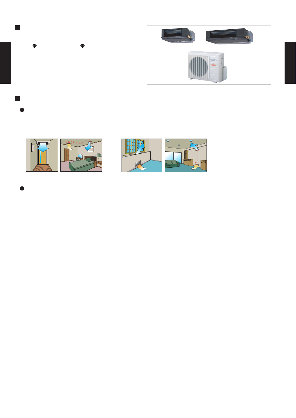
Universal design indoor unit
Since vertical and horizontal installation is possible, and the intake direction can also be selected
from two directions, flexible installation is possible.
Ceiling concealed Floor concealed
DUCT TYPE
AR18L - AR25L
Thin and compact indoor unit
- (02 - 01) -
Page 3
2-2. REMOTE CONTROLLER
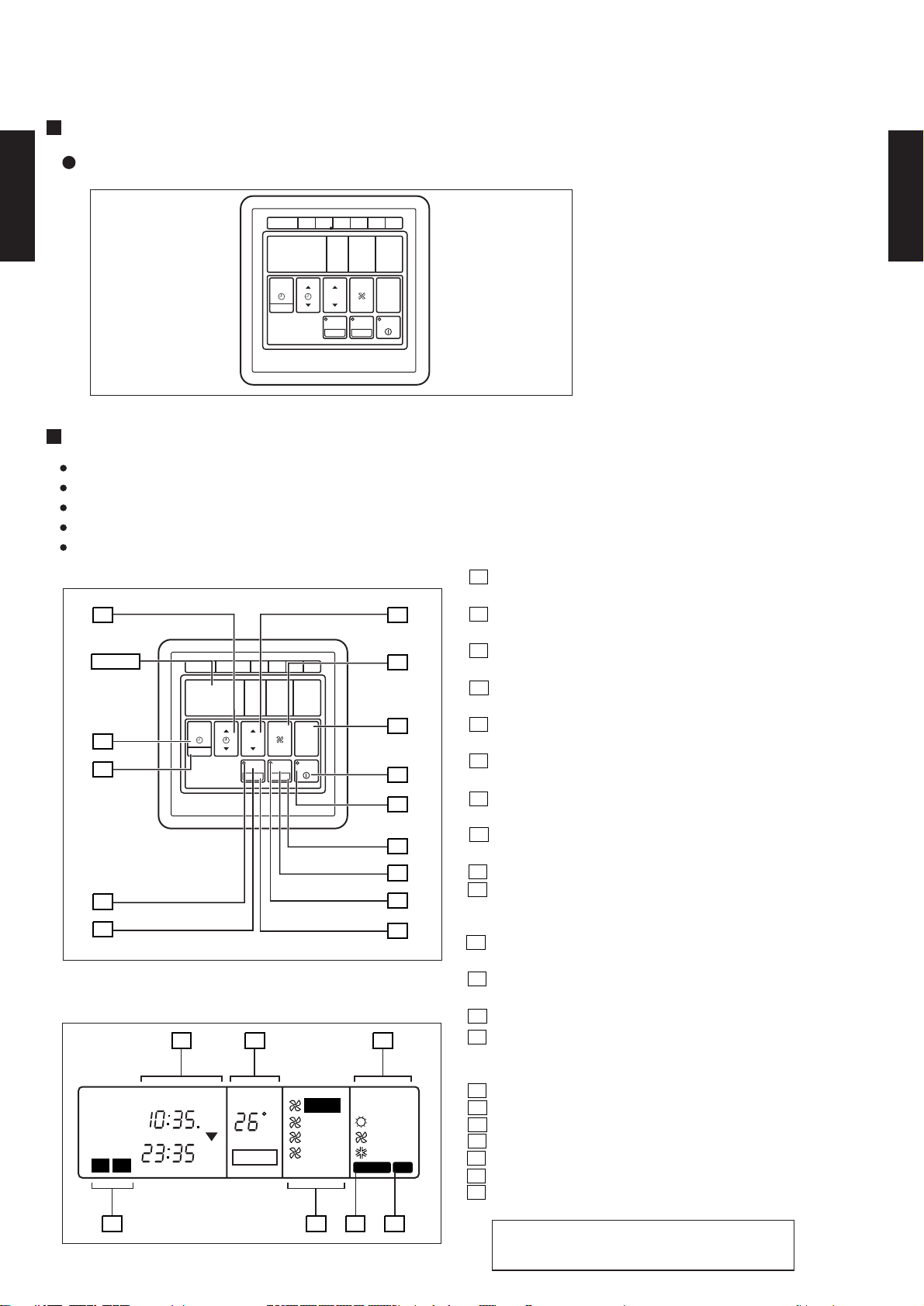
2-2-1. WIRED REMOTE CONTROLLER WITH WEEKLY TIMER
FEATURES
Three kinds of timer setup (OFF/ON/WEEKLY) are possible.
REMOTE CONTROLLER WITH WEEKLY TIMER
1
DAY CODE
MON2TUE3WED4THU5FRI6SAT
.
DUCT TYPE
AR18L - AR25L
TEMP./DAY
SET TIME
TIMER
MODE
CLOCK ADJUST
FUNCTIONS
Setting of different on-off time by day
Setting of set on-off time twice a day
Setting of time in 5 minute steps
Timer operation of a reserved day can be temporarily cancelled by pushing the DAY OFF button.
Time setting can be left until the next day.
FAN
CONTROL
MASTER
CONTROL
ENERGY SAVE
ZONE
SET
DAY OFF
START/STOP
DUCT TYPE
AR18L - AR25L
11
Display
10
9
8
7
Display panel
2
CLOCK
TIMER
NEXT DAY
NON STOP
OFFON
TIMER
WEEKLY
1
REMOTE CONTROLLER WITH WEEKLY TIMER
1
DAY CODE
MON2TUE3WED4THU5FRI6SAT
TEMP./DAY
SET TIME
TIMER
MODE
CLOCK ADJUST
FAN
CONTROL
MASTER
CONTROL
ENERGY SAVE
ZONE
SET
DAY OFF
START/STOP
1615
OFF
ON
ON
OFF
TEMP.
DAY
DAY OFF
AUTO
C
HIGH
MED
LOW
12
13
14
1
2
3
4
5
6
17
HEAT
FAN
COOL
DEFROST TEST
1 START/STOP Button
Pressed to start and stop operation.
2 OPERATION Lamp
Lights during operation and when the timer is on.
3 DAY OFF Button
Temporary cancellation of one day timer
4 ENERGY SAVE Button
Turns energy save mode on and off.
5 ENERGY SAVE Button
Lights when the unit is in the energy save mode.
6 SET Button
Sets the date, hour, minute and on-off time.
7 ZONE Button
Use to turn zone control on and off.
8
ZONE Lamp
Lights when the unit is in the zone control mode.
9 CLOCK ADJUST Button
10 TIMER MODE Button
Changes the timer mode (NON STOP, OFF TIMER,
ON TIMER, WEEKLY TIMER).
11 SET TIME Button
Sets the current time and on-off time.
12 TEMP./DAY Button
Sets the indoor temperature / day.
#
13 FAN CONTROL Button
14 MASTER CONTROL Button
Selects the operating mode
(HEAT, FAN, COOL).
15 Clock Display
16 Set Temperature / Day Display (TEMP./DAY)
17 Operation Mode Display
18 Timer Mode Display
#
19 Fan Speed Display
20 DEFROST Display
21 TEST Display
18
2019
21
#NOTE :
This model does not have a fan speed function.
- (02 - 02) -
Page 4
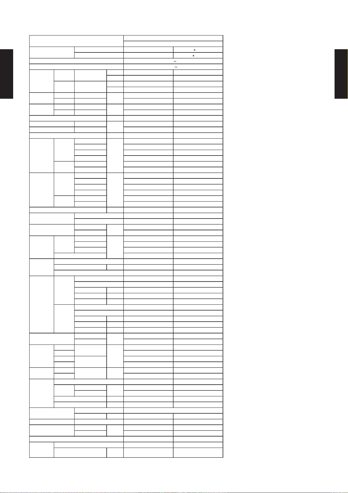
2-3. SPECIFICATIONS
ARG18ALCH AR 25ALCH
AOG18ANDKH AO 25ANAKH
Rows x Stages mm 2 x 12
2 x 12
Fin Pitch mm 1.5
1.5
Rows x Stages mm 1 x 12
1 x 12
Fin Pitch mm 1.5
1.5
Outer diameter 26.0
Inner diameter 21.5
Outer diameter 38.0
Inner diameter 36.0
DUCTED MODELS
220-240 50Hz
COOLING TYPE
198-264V 50Hz
OPERATION(OUTDOOR)
°C
REMOTE CONTROLLER TYPE
DRAIN PIPE
MATERIAL
SIZE
REFRIGERANT
TYPE
REFRIGERANT OIL
TYPE
WEIGHT
NET /
GROSS
kg(lbs)
PIPE
CONNECTION METHOD
SIZE
mm
MAX LENGTH
MAX HEIGHT
CASING COLOR
DIMENSIONS
H × W × D
NETmmGROSS
COMPRESSOR
TYPE
STARTING METHOD
HEAT
EXCHANGER
TYPE
INDOOR
Coil
Fin
OUTDOOR
Coil
Fin
NOISE LEVEL
(SOUND
PRESSURE)
COOL/HEAT
(at 240V)
INDOOR
dB(A)
OUTDOOR
RECOMMENDED STATIC PRESSURE
FAN TYPE x Q'ty
FAN MOTOR OUTPUT
W
FAN SPEED
COOL/HEAT
(at 240V)
INDOOR
r.p.m
OUTDOOR
MOISTURE REMOVAL
AIR
CIRCULATION
COOL/HEAT
(at 240V)
INDOOR
m3/h
OUTDOOR
CURRENT
A
STARTING CURRENT
kW/kW
HEATING
RATED
INPUT POWER
kW
R22
TYPE
MODEL NAME
INDOOR
OUTDOOR
POWER SOURCE
AVAILABLE VOLTAGE RANGE
CAPACITY
COOLING
RATED
DUCT TYPE
AR18L - AR25L
EER COOLING 2.79 - 2.70 2.64 - 2.51
COP HEATING - -
COOLING RATED 1.9 - 2.0 2.65 - 2.83
HEATING RATED - -
COOLING RATED 9.0 - 8.9 13.0 - 13.7
HEATING RATED - -
High 960 / - 1600 / -
Med 850 / - 1450 / -
Low 740 / - 1280 / -
Quiet - -
High 3400 / - 3200 / -
Low - -
High 1230 / - 890 / -
Med 1110 / - 820 / -
Low 990 / - 745 / -
Quiet - -
High 800 / - 800 / -
Low - -
INDOOR Sirocco Fan Sirocco x 2
OUTDOOR Propeller Fan Propeller x 1
INDOOR 45 70
OUTDOOR 65 65
High 43.0 / - 48.0 / -
Med 40.0 / - 45.0 / -
Low 36.0 / - 42.0 / -
OUTPUT W 1700 1700
kW 5.3 - 5.4 7.0 - 7.1
BTU/h 18000 - 18400 23900 - 24200
kW - -
BTU/h - -
A 48 69
l/h (pints/h) 1.6(3.4) 2.5 (5.3)
Pa 0 to 70 30 to 160
53.0 / - 54.0 / -
Rotary Rotary
Permanent Starting Condenser Permanent Starting Condenser
Copper tube
Alminum fin
Copper tube
Alminum fin
DUCT TYPE
AR18L - AR25L
Note: Specifications are based on the following conditions.
Cooling: Indoor temperature of 27 °CDB / 19 °CWB,and outdoor temperature of 35 °CDB/24 °CWB.
Heating: Indoor temperature of 20 °CDB / 15 °CWB,and outdoor temperature of 7 °CDB/6 °CWB.
Static pressure of measurement : 0Pa
Pipe length : 7.5 m, Height difference : 0 m.(Outdoor unit - Indoor unit)
Coil Dimensions mm 308 x 700 x 38.1
Copper tube
Alminum fin
Coil Dimensions mm 610 x 905 x 19.05
INDOOR Galvanized steel sheet Galvanized steel sheet
OUTDOOR Beige(10YR7.5/1.0NN) Beige(10YR7.5/1.0NN)
INDOOR 217 x 953 x 595 270 x 1210 x 700
OUTDOOR 650 x 830 x 320 643 x 840 x 336
INDOOR 324 x 1075 x 686 330 x 1300 x 790
OUTDOOR 743 x 984 x 413 750 x 959 x 429
INDOOR 25 / 29 (55 / 64) 43 / 58 (19.5 / 26.3)
OUTDOOR 51 / 55 (112 / 121) 65 / 73 ( 29.5 / 33.1)
FLARE FLARE
LIQUID 9.53 ( 3 / 8 inc.) 9.53 ( 3 / 8 inc.)
GAS 15.88 ( 5 / 8 inc.) 15.88 ( 5 / 8 inc.)
m 20(chargeless:7.5) 25(chargeless:7.5)
m 8 15
CHARGE kg 1.25 2.05
POE Mineral oil
COOLING 21 to 52 21 to 52
HEATING - -
EZ-0001 WSEFR EZ-0001 WSEFR
308 x 700 x 38.1
Copper tube
Alminum fin
610 x 905 x 19.05
Steel Steel
mm
- (02 - 03) -
Page 5
2-4. DIMENSIONS
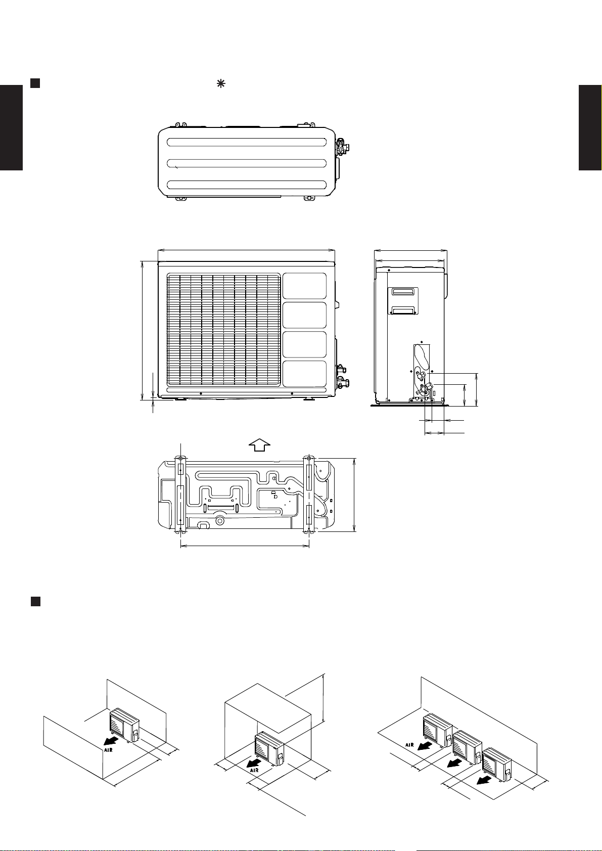
2-4-1. OUTDOOR UNIT
MODELS : AOG18A, AO 25A
DUCT TYPE
AR18L - AR25L
Top view
(Unit : mm)
DUCT TYPE
AR18L - AR25L
830
650
12
Front view
Bottom
Air flow
343
350
320
Side view
154
101
58
90
MOUNTING POSITION
When there are obstacles at the
back or front sides.
100 mm
or more
600 mm
or more
Bottom view
100 mm
or more
603
When there are obstacles at the
back, side(s), and top.
600 mm or more
300 mm
250
(
mm or
S
er
v
i
c
e s
more
pac
e)
or more
When there are obstacles at the
back, side with the installation of
more than one unit.
250 mm
or more
250 mm
or more
300 mm
or more
- (02 - 04) -
Page 6
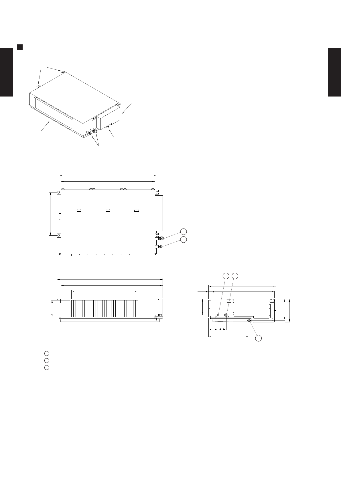
2-4-2. INDOOR UNIT
MODEL : ARG18A
BRACKETS
DUCT TYPE
AR18L - AR25L
CONTROL BOX
AIR FLOW OUTLET
DRAIN PORT(Ø25.4)
COUPLING PIPE ASSY
886
850
(Unit : mm)
DUCT TYPE
AR18L - AR25L
390
Top view
953
920
600
150
Front view
1
Refrigerant piping flare connection (Gas)
2
Refrigerant piping flare connection (Liquid)
3
Drain piping connection
1
2
12
605
57520
150
85 75
Side view
364
3
194
217
- (02 - 05) -
Page 7
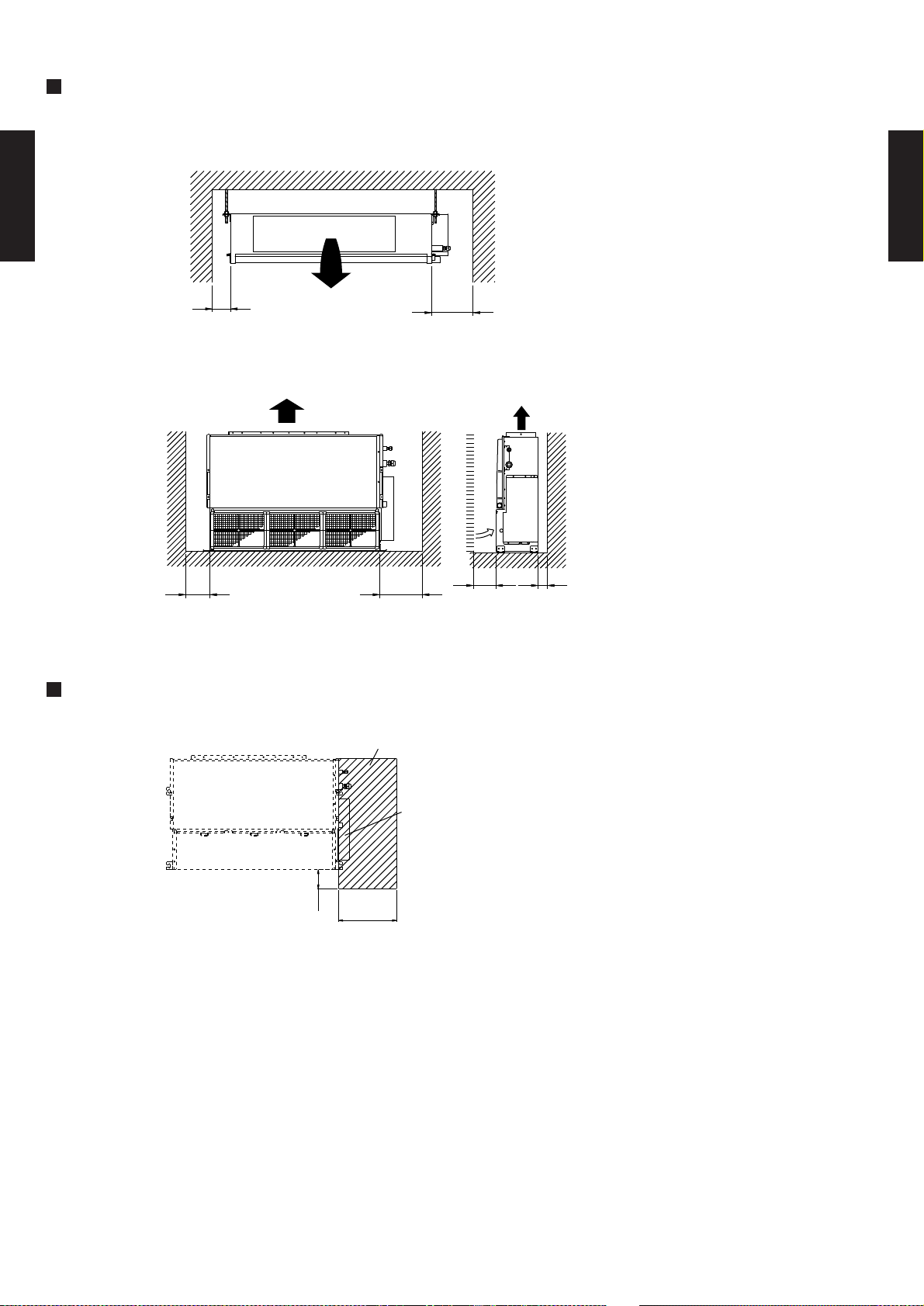
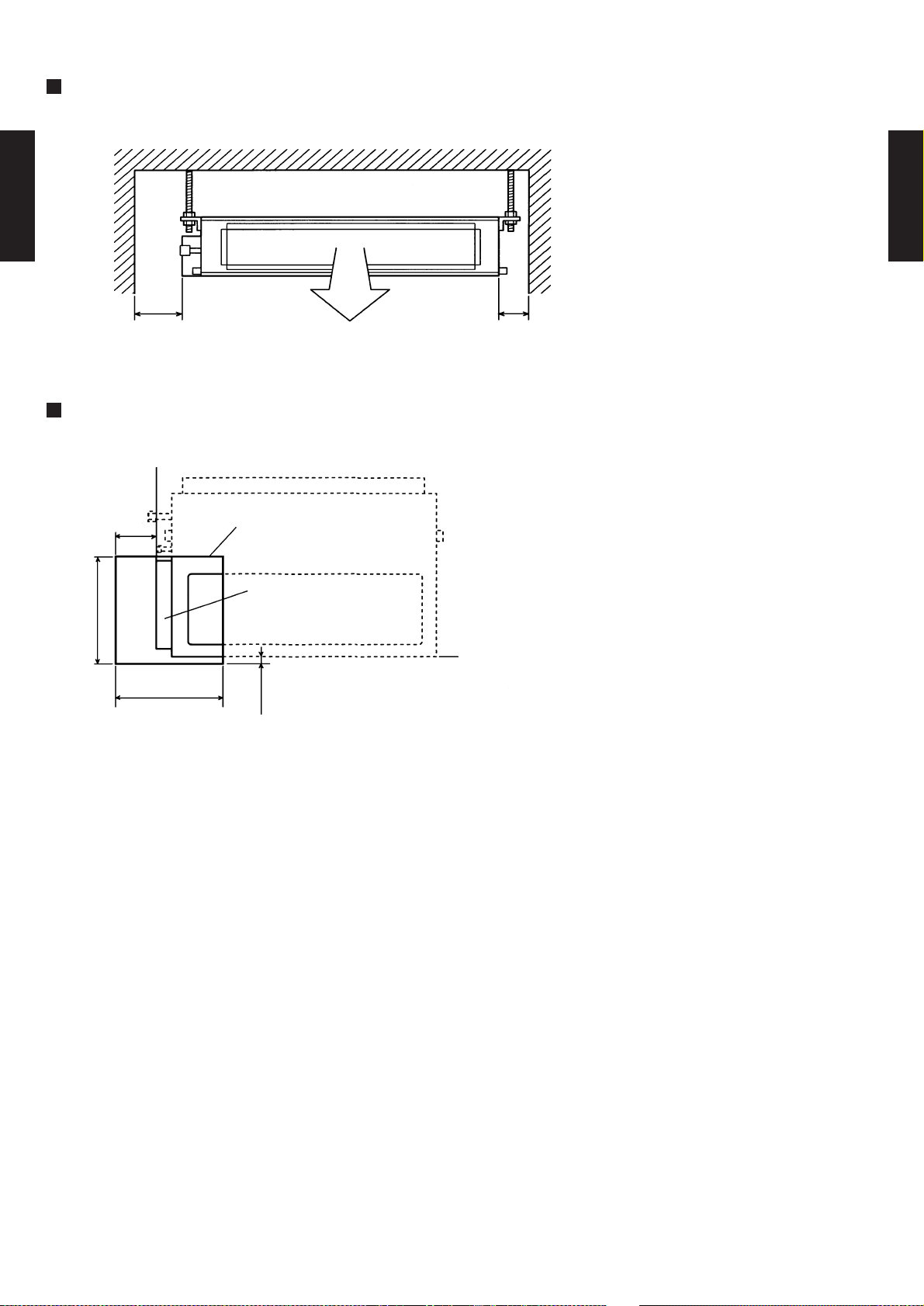
MOUNTING POSITION
Strong and durable ceiling
Indoor unit
30mm
or more
Right
side
30mm
or more
DUCT TYPE
AR18L - AR25L
Left
DUCT TYPE
AR18L - AR25L
side
Left
side
100mm
or more
100mm
or more
Strong and durable floor
300mm
or more
Right side
(PIPE side)
300mm
or more
MAINTENANCE HOLE
Unit
Service hole
Control box
300mm
100mm
or more
or more
- (02 - 06) -
Page 8
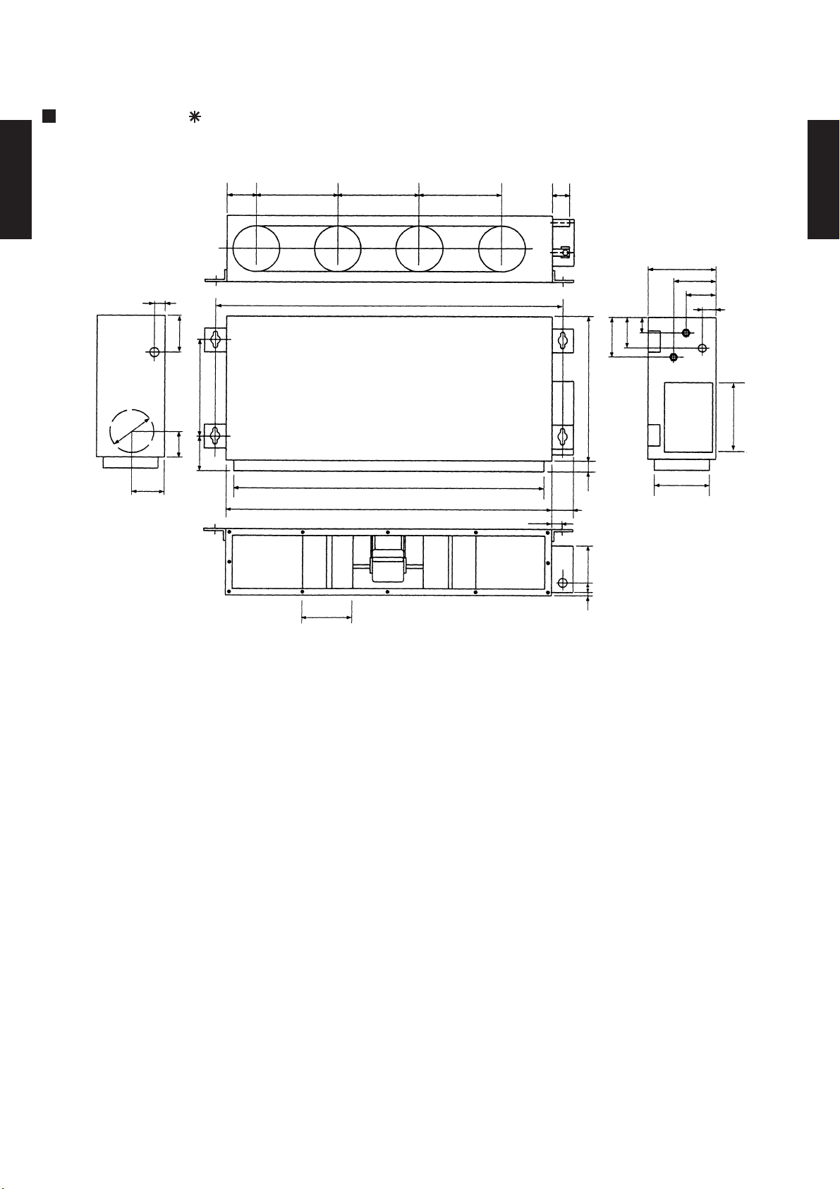
MODEL : AR 25A
(Unit : mm)
139 264 264 264
DUCT TYPE
AR18L - AR25L
26
197
46996
200
141
117
220
1,177
1,063
1,135
42
75
83
DUCT TYPE
AR18L - AR25L
270
96
58
26
196
126
243
700
382
4066 184
68
205
- (02 - 07) -
Page 9
MOUNTING POSITION
Indoor unit
Left
DUCT TYPE
side
AR18L - AR25L
300mm or more 150mm or more
Right
side
DUCT TYPE
AR18L - AR25L
MAINTENANCE HOLE
200mm
500mm
Maintenance hole
Control box metal
500mm
500mm
- (02 - 08) -
Page 10

2-5. REFRIGERANT CIRCUIT
MODELS : ARG18A / AOG18A
Refrigerant pipe
OUTDOOR UNITINDOOR UNIT
Distributor
DUCT TYPE
AR18L - AR25L
THPI
THR
Evaporator
THRMISTOR(ROOM TEMP.)THR
THRMISTOR(PIPE TEMP.)THPI
9.52mm (3/8")
Refrigerant pipe
15.88mm (5/8")
Charging valve
Capillary tube
Compressor
Dryer
Pressure
switch
Condenser
DUCT TYPE
AR18L - AR25L
MODELS : AR 25A / AO 25A
INDOOR UNIT
Refrigerant pipe
9.52 mm (3/8")
THPI
THR
Evaporator
Refrigerant pipe
15.88 mm (5/8")
Charging valve
Capillary tube
Accumulator
OUTDOOR UNIT
Dryer
Condenser
Compressor
Pressure
switch
THRMISTOR(ROOM TEMP.)THR
THRMISTOR(PIPE TEMP.)THPI
- (02 - 09) -
Page 11

2-6. WIRING DIAGRAMS
2-6-1. OUTDOOR UNIT
MODEL : AOG18A
INTERNAL
OVERLOAD
DUCT TYPE
AR18L - AR25L
PROTECTOR
C
BLACK
1
4
MAIN RELAY
R
COMPRESSOR
S
6
5
BLACK
COMPRESSOR
CAPACITOR
RED
WHITE
RED
BLACK
FAN MOTOR
DUCT TYPE
AR18L - AR25L
THERMAL
PROTECTOR
WHITE
WHITE
BROWN
BROWN
WHITE WHITE
BLACK
FAN MOTOR
CAPACITOR
FUSE 5A
BLACK
PRESSURE
SWITCH
BLACK
TO POWER SUPPLY
MODEL : AO 25A
INTERNAL
OVERLOAD
PROTECTOR
C
BLACK
1
4
MAIN RELAY
R
COMPRESSOR
S
6
5
BLACK
COMPRESSOR
CAPACITOR
RED
LN 2(N)3
WHITE WHITE
WHITE
BROWN
BROWN
BLACK
RED
1
TERMINAL
WHITE
WHITE
FAN MOTOR
CAPACITOR
FUSE 5A
BLACK
TO INDOOR UNIT
THERMAL
PROTECTOR
PRESSURE
SWITCH
BLACK
FAN MOTOR
BLACK
TO POWER SUPPLY
LN 2(N)3
1
- (02 - 10) -
TERMINAL
TO INDOOR UNIT
Page 12

2-6-2. INDOOR UNIT
MODEL : ARG18A
GREEN/YELLOW
FAN
MOTOR
FM
FAN MOTOR
CAPACITOR
BLACK
WHITE
DUCT TYPE
AR18L - AR25L
WHITE
BLACK
Use T3.15A - 250V
FILTER BOARD
Fuse on F101
GRAY
1
2
3 2 1
CN1
132
GREEN
WHITE
BLACK
132
REMOTE
CONTROL
CONTROL UNIT
456
RED
RED
CN5
CN17
BLUE
PURPLE
PINK
WHITE
123
BOARD
BLACK
WHITE
WHITE
1
2
CN4
CONTROL
(N)
2
1
OUTDOOR UNIT
CONTROL
TO OUTDOOR UNITTO REMOTE
DUCT TYPE
AR18L - AR25L
1
2
1
2
3
CN15CN9
3
CN6
CN7
2 1
GRAY
GRAY
CN8
2 1
BLACK
BLACK
TERMINAL
THERMISTOR (PIPE TEMP.)
THERMISTOR (ROOM TEMP.)
MODEL : AR 25A
- (02 - 11) -
Page 13

2-7. CAPACITY TABLE
Outdoor temperature
15 °CWB
18 °CDB
12 °CWB
29 °CDB
21 °CWB
16 °CWB
22 °CWB
Indoor temperature
32 °CDB
23 °CWB
27 °CDB
30 °CDB
18 °CWB
19 °CWB
26 °CDB
23 °CDB
21 °CDB
Outdoor temperature
15 °CWB
18 °CDB
12 °CWB
29 °CDB
21 °CWB
16 °CWB
22 °CWB
Indoor temperature
32 °CDB
23 °CWB
27 °CDB
30 °CDB
18 °CWB
19 °CWB
26 °CDB
23 °CDB
21 °CDB
MODELS : ARG18A / AOG18A
COOLING
AFR 16.0
(°CDB) TC SHC PI TC SHC PI TC SHC PI TC SHC PI TC SHC PI T C SHC PI TC SHC PI T C SHC PI
DUCT TYPE
AR18L - AR25L
MODELS : AR 25A / AO 25A
21 5.71 4.26 1.45 5.86 4.28 1.48 6.01 4.30 1.49 6.22 4.56 1.50 6.33 4.54 1.52 6.50 4.50 1.55 6.58 4.48 1.56 6.66 4.71 1.58
25 5.62 4.39 1.62 5.76 4.41 1.64 5.89 4.43 1.65 6.11 4.68 1.67 6.20 4.66 1.68 6.37 4.61 1.71 6.45 4.58 1.72 6.52 4.81 1.72
30 5.26 4.19 1.77 5.41 4.21 1.79 5.54 4.26 1.80 5.74 4.51 1.83 5.84 4.49 1.84 6.01 4.45 1.87 6.09 4.43 1.88 6.17 4.66 1.89
35 4.90 4.01 1.93 4.99 4.04 1.94 5.12 4.07 1.96 5.31 4.31 1.99 5.40 4.30 2.00 5.57 4.27 2.03 5.66 4.26 2.04 5.74 4.49 2.05
40 4.45 3.81 2.10 4.52 3.83 2.10 4.63 3.84 2.12 4.82 4.09 2.15 4.91 4.09 2.16 5.07 4.07 2.20 5.16 4.06 2.21 5.24 4.30 2.24
45 4.14 3.63 2.19 4.21 3.68 2.20 4.31 3.69 2.21 4.50 3.95 2.24 4.59 3.95 2.26 4.76 3.94 2.29 4.85 3.94 2.31 4.94 4.18 2.32
50 3.93 3.29 2.24 4.00 3.33 2.26 4.10 3.59 2.27 4.28 3.86 2.31 4.37 3.86 2.32 4.54 3.85 2.36 4.63 3.85 2.38 4.72 4.10 2.39
52 3.79 3.24 2.27 3.90 3.28 2.29 3.99 3.55 2.30 4.18 3.81 2.34 4.27 3.81 2.35 4.44 3.81 2.39 4.53 3.81 2.41 4.62 4.06 2.42
COOLING
AFR 26.7
DUCT TYPE
AR18L - AR25L
(°CDB) TC SHC PI TC SHC PI TC SHC PI TC SHC PI TC SHC PI TC SHC PI TC SHC PI T C SHC PI
21 7.51 5.33 2.08 7.70 5.35 2.12 7.90 5.38 2.11 8.14 5.70 2.17 8.28 5.69 2.19 8.47 5.64 2.24 8.60 5.61 2.26 8.70 5.89 2.28
25 7.39 5.49 2.29 7.57 5.52 2.31 7.75 5.55 2.33 8.03 5.86 2.37 8.16 5.83 2.38 8.38 5.77 2.41 8.48 5.74 2.43 8.58 6.01 2.44
30 6.92 5.24 2.51 7.12 5.27 2.53 7.28 5.33 2.55 7.55 5.64 2.59 7.67 5.62 2.60 7.90 5.57 2.64 8.01 5.55 2.66 8.11 5.83 2.67
35 6.44 5.02 2.73 6.56 5.06 2.75 6.73 5.09 2.77 6.98 5.39 2.81 7.10 5.38 2.83 7.33 5.35 2.87 7.44 5.33 2.89 7.55 5.62 2.90
40 5.86 4.76 2.97 5.94 4.79 2.98 6.08 4.81 2.99 6.33 5.12 3.04 6.45 5.11 3.06 6.67 5.09 3.11 6.78 5.08 3.13 6.89 5.38 3.17
45 5.44 4.55 3.10 5.54 4.60 3.11 5.67 4.62 3.13 5.91 4.94 3.17 6.03 4.94 3.20 6.25 4.93 3.25 6.38 4.93 3.26 6.49 5.23 3.29
50 5.14 4.12 3.17 5.26 4.16 3.20 5.39 4.50 3.22 5.63 4.83 3.26 5.75 4.83 3.29 5.97 4.82 3.34 6.09 4.82 3.36 6.21 5.13 3.38
52 5.00 4.05 3.20 5.12 4.10 3.24 5.25 4.44 3.26 5.50 4.77 3.31 5.61 4.77 3.33 5.84 4.77 3.38 5.96 4.77 3.41 6.07 5.08 3.43
AFR: Air flow rate (m3/min)
TC : Total capacity (kW)
SHC: Sensible Heat capacity (kW)
PI : Power Input (kW)
- (02 - 12) -
Page 14

2-8. CAPACITY COMPENSATION FOR PIPE LENGTH
5 7.5 10 15 20 25
15 - - - 0.970 0.950 0.930
10 - - 0.990 0.970 0.950 0.930
7.5 - 1.000 0.990 0.970 0.950 0.930
5 1.010 1.000 0.990 0.970 0.950 0.930
0 1.010 1.000 0.990 0.970 0.950 0.930
-5 1.005 0.995 0.985 0.965 0.945 0.925
-7.5 - 0.990 0.982 0.962 0.942 0.922
-10 - - 0.980 0.960 0.940 0.920
-15 - - - 0.955 0.935 0.918
HEIGHT DIFFERENCE (m)
Outdoor unit
is bottom-side
Outdoor unit
is up-side
PIPE LENGTH (m)
5 7.5 10 15 20
- - - - -
8 - 1.000 0.990 0.970 0.950
5 1.010 1.000 0.990 0.970 0.950
0 1.010 1.000 0.990 0.970 0.950
-5 1.002 0.992 0.982 0.962 0.942
-8 - 0.988 0.978 0.958 0.939
- - - - -
PIPE LENGTH (m)
HEIGHT DIFFERENCE (m)
Outdoor unit
is up-side
Outdoor unit
is bottom-side
AND HEIGHT DIFFERENCE
MODELS : ARG18A / AOG18A
DUCT TYPE
AR18L - AR25L
DUCT TYPE
AR18L - AR25L
MODELS : AR 25A / AO 25A
- (02 - 13) -
Page 15

2-9. ADDITIONAL CHARGE CALCULATION
REFRIGERANT AMOUNT g
REFRIGERANT TYPE
R22
1,250
PIPE LENGTH m
7.5
10 15 20 (MAX)
ADDITIONAL CHARGE g 0 (Charge less) 50 150 250
20g/m
REFRIGERANT AMOUNT g
REFRIGERANT TYPE
R22
2,050
PIPE LENGTH m
7.5
10 15 20 25 (MAX)
ADDITIONAL CHARGE g 0 (Charge less) 50 150 250 350
20g/m
MODEL : ARG18A
DUCT TYPE
AR18L - AR25L
REFRIGERANT CHARGE
MODEL : AR 25A
DUCT TYPE
AR18L - AR25L
REFRIGERANT CHARGE
- (02 - 14) -
Page 16

2-10. OPERATION RANGE
ARG18A
AR 25A
AOG18A
AO 25A
Cooling
Dry
Operation Range
Model
Mode
Indoor unit Outdoor unit Indoor temperature Indoor humidity
Outdoor temperature
18 to 32 °C About 80% or less 21 to 52°C
DUCT TYPE
AR18L - AR25L
DUCT TYPE
AR18L - AR25L
- (02 - 15) -
Page 17

2-11. FAN PERFORMANCE AND AIR FLOW
30 40 50 60 70
m3/h
- 750 675 600 530
l/s - 208 188 167 147
CFM - 441 397 353 312
m3/h
- 685 615 545 -
l/s - 190 171 151 -
CFM - 403 362 321 -
m3/h
700 635 555 - -
l/s 194 176 154 - -
CFM 412 374 327 - -
240V
STATIC PRESSRE
FAN SPEED
Hi
Med
Low
MODELS : ARG18A / AOG18A
240V
DUCT TYPE
AR18L - AR25L
DUCT TYPE
AR18L - AR25L
Q-h Characteristic curve
80
70
60
50
40
30
20
STATIC PRESSURE(Pa)
10
0
500 550 600 650 700 750 800
AIR FLOW (m3/h)
Test condition : No filter and Fan mode
Hi
Med
Low
- (02 - 16) -
Page 18

MODELS : AR 25A / AO 25A
25 30 40 50 60 70 75 100 125 150
m3/h
1450 1434 1390 1350 1300 1255 1230 1095 925 695
l/s 403 398 386 375 361 349 342 304 257 193
CFM 853 844 818 794 765 739 724 644 544 409
m3/h
1330 1310 1275 1235 1190 1150 1125 990 795 -
l/s 369 364 354 343 331 319 313 275 221 -
CFM 783 771 750 727 700 677 662 583 468 -
m3/h
1120 1100 1065 1030 990 945 925 795 - -
l/s 311 306 296 286 275 263 257 221 - -
CFM 659 647 627 606 583 556 544 468 - -
Me d
Low
STATIC PRES S RE
240V
FAN S P EED
Hi
240V
DUCT TYPE
AR18L - AR25L
Q-h Characteristic curve
160
140
120
Hi
Med
Low
DUCT TYPE
AR18L - AR25L
100
80
60
40
STATIC PRESSURE(Pa)
20
0
500 600 700 800 900 1000 1100 1200 1300 1400 1500
AIR FLOW (m3/h)
Test condition : No filter and Fan mode
- (02 - 17) -
Page 19

2-12. NOISE LEVEL
External Static
Pressure (Pa)
Blower
Speed
63 125 250 500 1000 2000 4000
Hi 63.8 54.9 57.5 57.6 52.1 47.8 36.2
Me 62.4 51.7 54.8 55.4 49.2 44.7 36.4
Lo 62.1 49.0 51.3 51.4 44.4 38.4 31.9
Hi 65.2 60.1 63.5 62.8 58.2 51.0 43.0
Me 64.5 59.8 61.3 60.4 55.8 48.6 40.8
Lo 63.7 57.6 59.1 58.1 53.4 44.5 38.3
AR 25A
50
Octave Band Center Frequency (Hz)
Condition
Model Name
ARG18A
50
Sound Power Level(db)Of Medium Static Pressure Ducted A/C
DUCT TYPE
AR18L - AR25L
DUCT TYPE
AR18L - AR25L
- (02 - 18) -
Page 20

SOUND LEVEL CHECK POINT
OUTDOOR UNIT
DUCT TYPE
AR18L - AR25L
Center
Center
Side view
Front view
INDOOR UNIT
DUCT TYPE
AR18L - AR25L
CenterCenter
Front viewSide view
- (02 - 19) -
Page 21

2-13. ELECTRIC CHARACTERISTICS
Main Fuse (Circuit breaker)
Current
m
m
2
*2) Limited Wiring length : This is the wiring length in case voltage descent is less than 2%.
Outdoor Fan Motor
0.148
220-240
50
0.148
0.73
0.73
20
Indoor Fan Motor
0.94
1.20
0.39
0.50
30
2.5-3.5
3.5-4.0
Model Name
Rated Value
Mode
*1) Wiring Spec
20
20
Power Supply
ARG18A
AR 25A
AOG18A
AO 25A
MODELS : ARG18A / AOG18A, AR 25A / AO 25A
Indoor unit
Outdoor unit
Voltage V
Frequency Hz
DUCT TYPE
AR18L - AR25L
Current A 9.0-8.9 - 13.0-13.7 -
Input kW 1.9-2.0 - 2.65-2.83 -
Max Operating Current A 15.5 - 18.5 -
Starting Current A 48 - 69 -
Power Cable
*2)Limited wiring length m
DUCT TYPE
Cooling Heating Cooling Heating
AR18L - AR25L
A
Input kW
Full Load Amp. A
Input kW
Full Load Amp. A
*1) Wiring Spec : Selected Sample
(Selected based on Japan Electrotechnical Standard and Codes Committee E0005)
When the wiring length becomes long, please select the wiring of a more larger
diameter.
- (02 - 20) -
Page 22

2-14. SAFETY DEVICE
PROTECTION FORM AOG18ANDKH
AO 25ANAKH
FUSE - 5A 250V 5A 250V
FAN MOTOR PROTECTOR THERMAL PROTECTOR 150±5°C OFF 150±5°C OFF
COMPRESSOR THERMAL PROTECTOR 120±5°C OFF 165±5°C OFF
OFF 3.5 - 0.15MPa OFF 3.5 - 0.15MPa
ON 2.65 ±0.15MPa ON 2.65 ±0.15MPa
HIGH PRESSURE PROTECTION
PRESSURE SWITCH
PROTECTION FORM ARG18ALCH
AR 25ALC
PCB FUSE 3.15A 250V 3.15A 250V
FAN MOTOR PROTECTOR THERMAL PROTECTOR 150±5°C OFF 150±5°C OFF
OUTDOOR UNIT
DUCT TYPE
AR18L - AR25L
INDOOR UNIT
DUCT TYPE
AR18L - AR25L
- (02 - 21) -
Page 23

2-15. FUNCTION SETTING
Zone control setting
Room temperature correct coefficient of heating
Room temperature correct coefficient of heating
Forbidden
Forbidden
Fan delay setting
Indoor unit number setting
Forbidden
Forbidden
Forbidden
INDOOR UNIT
DIP SW
Rotary SW
SW 2
3
1
JM3
SW 1
SW 4
Jumper Wire
23JM1
JM2
1
2
2-15-1. INDOOR UNIT
DUCT TYPE
AR18L - AR25L
SWITCH POSITION
DUCT TYPE
AR18L - AR25L
Indoor unit control circuit board
- (02 - 22) -
Page 24

SW 1-1
SW state
OFF
Invalidity
ON
Validity
2-15-2. SWITCH FUNCTION (INDOOR UNIT)
SW 4-1
OFF
SW 4-2
OFF
OFF
Invalidity
Validity
ON
SW 4-3
SW state
0 deg (Floor setting)
ONON+4 deg (Ceiling setting)
SW 1-2
SW state
+2 deg
-2 deg
SW 1-3
OFF
OFF
OFF
ON
OFF
ON
DIP SWITCH SETTING
SW1-1. Zone control setting
Zone control function can be selected by turning this switch ON/OFF.
Zonecontrol SETTING
DUCT TYPE
AR18L - AR25L
SW1-2. Room temperature correct coefficient of heating.
Decide the heating temperature correct coefficient vale of heating.
HEAT TEMPERATURE CORRECTION
( Factory setting)
( Factory setting)
DUCT TYPE
AR18L - AR25L
SW 4-1.Dip SW 4-1 setting forbidden
( Factory setting)
SW 4-2.Dip SW 4-2 setting forbidden
( Factory setting)
SW4-3. 4-3.Fan delay setting
This setting can be used when the auxiliary heater is mounted.
When the fan operation is stopped when the indoor unit is operating with an auxiliary heater,
the fan operation continues one minutes.
( Factory setting)
- (02 - 23) -
Page 25

ROTARY SWITCH SETTING
0
Single
1 - 15
Indoor unit address
SW 2
SW state
JM state
JM 1
Connect
Disconnect
Forbidden
JM state
JM 2,3
Connect
Disconnect
Forbidden
-
-
-
See external input/output
settings for details.
CN10
-
ELECTRICAL HEATER
Connector
INPUT
OUTPUT
REMARKS
This switch can be used when group control system.
Set the indoor unit address in the 1,2,-,15 order.
( Factory setting)
DUCT TYPE
AR18L - AR25L
DUCT TYPE
AR18L - AR25L
JUMPER WIRE SETTING
JM 1, 2, 3 setting forbidden
( Factory setting)
( Factory setting)
EXTERNAL INPUT AND OUTPUT
- (02 - 24) -
Page 26

2-15-3. WIRED REMOTE CONTROLLER CIRCUIT BOARD
Jumper Wire
Wired remote controller
DIP SW
SW1
Group control setting
(Unit address NO. setting)
SW2
1
2
3
4
DUCT TYPE
AR18L - AR25L
5 Forbidden
6 Indoor unit connection(Single/Multiple)
1 Cooling / Heat pump
2 Auto restart validity / invalidity
3 Forbidden
4 Defrost display
5 Forbidden
6 Memory backup switch
JM1 Forbidden
JM2 Forbidden
JM3 Forbidden
JM4 Auto change over validity / invalidity
JM5 Forbidden
JM6 Forbidden
DUCT TYPE
AR18L - AR25L
SWITCH POSITION
Wired remote controller
N
N
O
O
2
2
345
1
Dip switch 1 Dip switch 2
4
5
3
6
1
6
- (02 - 25) -
Page 27

2-15-4. WIRED REMOTE CONTROLLER
DIP SW 1-5
OFF
Number of indoor unit
One unit connection
Multiple unit connection
DIP SWITCH SETTING
SW1 setting
1-1 Unit address No. setting
Set remoto controller the SW1-6 toON.
DUCT TYPE
AR18L - AR25L
Set the address number of additional indoor unit with remote controller SW1-(1-4).
For the address number of additional connected units, see the table below.
SW1-1 SW1-2 SW1-3 SW1-4 SW1-5 SW1-6 Indoor unit address
OFF OFF OFF OFF OFF OFF Single
OFF OFF OFF ON OFF ON 1
OFF OFF ON OFF OFF ON 2
OFF OFF ON ON OFF ON 3
OFF ON OFF OFF OFF ON 4
OFF ON OFF ON OFF ON 5
OFF ON ON OFF OFF ON 6
OFF ON ON ON OFF ON 7
ON OFF OFF OFF OFF ON 8
ON OFF OFF ON OFF ON 9
ON OFF ON OFF OFF ON 10
ON OFF ON ON OFF ON 11
ON ON OFF OFF OFF ON 12
ON ON OFF ON OFF ON 13
ON ON ON
ON ON ON ON
OFF OFF ON 14
OFF ON 15
( Factory setting)
DUCT TYPE
AR18L - AR25L
SELF DIAGNOSIS
If [EE : EE] flashes at the remote controller current time displey, per-form[Self Diagnosis]
For the [Self Diagnosis] method, refer to the test operetion section of the installation
The faulty air conditioner is also displayed.
Example
[ 22 : 03 ] : Unit 03 room temperature sensor open
Faulty unit !
Error cord
DIP SW 1-5 setting forbidden.
( Factory setting)
Number of indoor unit conneection(Single/Multiple)
This is switchsd according to the number of connected indoor units.
NUMBER OF INDOOR UNIT CONNECTION
( Factory setting)
SW 1-6
OFF
ON
- (02 - 26) -
Page 28

SW2 setting
Battery backup
Invalidity
Validity
Defrost display
Invalidity
Validity
Operation system
Heat pump/Heat recovery
Cooling only
Invalidity
Validity
Auto restart
DIP SW2-5
OFF
DIP SW2-5
OFF
2-1 Cooling only heat pump
Switching cooling only / heat pump
COOLING ONLY / HEAT PUMP SWITCH
DUCT TYPE
AR18L - AR25L
(
(
Factory setting in case of cooling only Model )
Factory setting, in case of Heat pomp Model )
DUCT TYPE
AR18L - AR25L
SW2-2
OFF
ON
2-2 Auto restart validity/invalidity
Selecting auto restart invalidity/validity
In the case of it is ON, to set the SW2-6 ON.
AUTO RESTART
( Factory setting)
SW2-2
OFF
ON
2-3 DIP SW 2-3 setting forbidden
( Factory setting)
2-4 Defrost display invalidity/validity mark is displayed.
DEFROST
(
(
Factory setting in case of cooling only Model )
Factory setting, in case of Heat pomp Model )
SW2-4
OFF
ON
2-5 DIP SW 2-5 setting forbidden
( Factory setting)
2-6 Memory backup switch (wired remote controller only)
When installing, turn the SW2-6 ON.
MEMORY BACKUP SWITCH
DIP SW2-6
OFF
ON
( Factory setting)
- (02 - 27) -
Page 29

JUMPER WIRE SETTING
JM1 JM state
JM2 JM state
JM3 JM state
JM4 Auto change over
JM5 JM state
JM6 JM state
Forbidden
Forbidden
Forbidden
Forbidden
Forbidden
1. JM1 setting forbiden
( Factory setting)
Connect
Disconnect
DUCT TYPE
AR18L - AR25L
2. JM2 setting forbiden
( Factory setting)
Connect
Disconnect
3. JM3 setting forbiden
( Factory setting)
Connect
DUCT TYPE
AR18L - AR25L
Disconnect
4. Auto change over setting
selecting auto change over validity / invalidity
( Factory setting)
Connect validity
Disconnect invalidity
5. JM5 setting forbiden
( Factory setting)
Connect
Disconnect
6. JM6 setting forbiden
( Factory setting)
Connect
Disconnect
- (02 - 28) -
 Loading...