

Page 1
CONCEALED TYPE
SPLIT AIR CONDITIONER
TECHNICAL MANUAL
Page 2

CONTENTS
1. FEATURES.........................................................................2
2. OUTLINE AND DIMENSIONS............................................4
2.1 INDOOR UNIT..................................................................... 4
2.2 OUTDOOR UNIT.................................................................. 5
3. PERFORMANCE DATA.....................................................6
3.1 PERFORMANCE CURVE .................................................... 6
3.2 FAN CURVE ......................................................................... 7
3.3 CAPACITY BY AIR FLOW.................................................... 7
3.4 OUTLET AIR TEMPERATURE............................................. 7
3.5 TEMPERATURE RANGE ..................................................... 8
3.6 REFRIGERANT CHARGE ................................................... 8
4. SPECIFICATIONS..............................................................9
– 1 –
Page 3
1. FEATURES
■
DUCT SPLIT TYPE FEA TURES
• Installed behind the ceiling this design offers space savings and low noise.
• With a beautiful finish, the outlet grille does not stick out into the room.
■
PRODUCT FEATURES
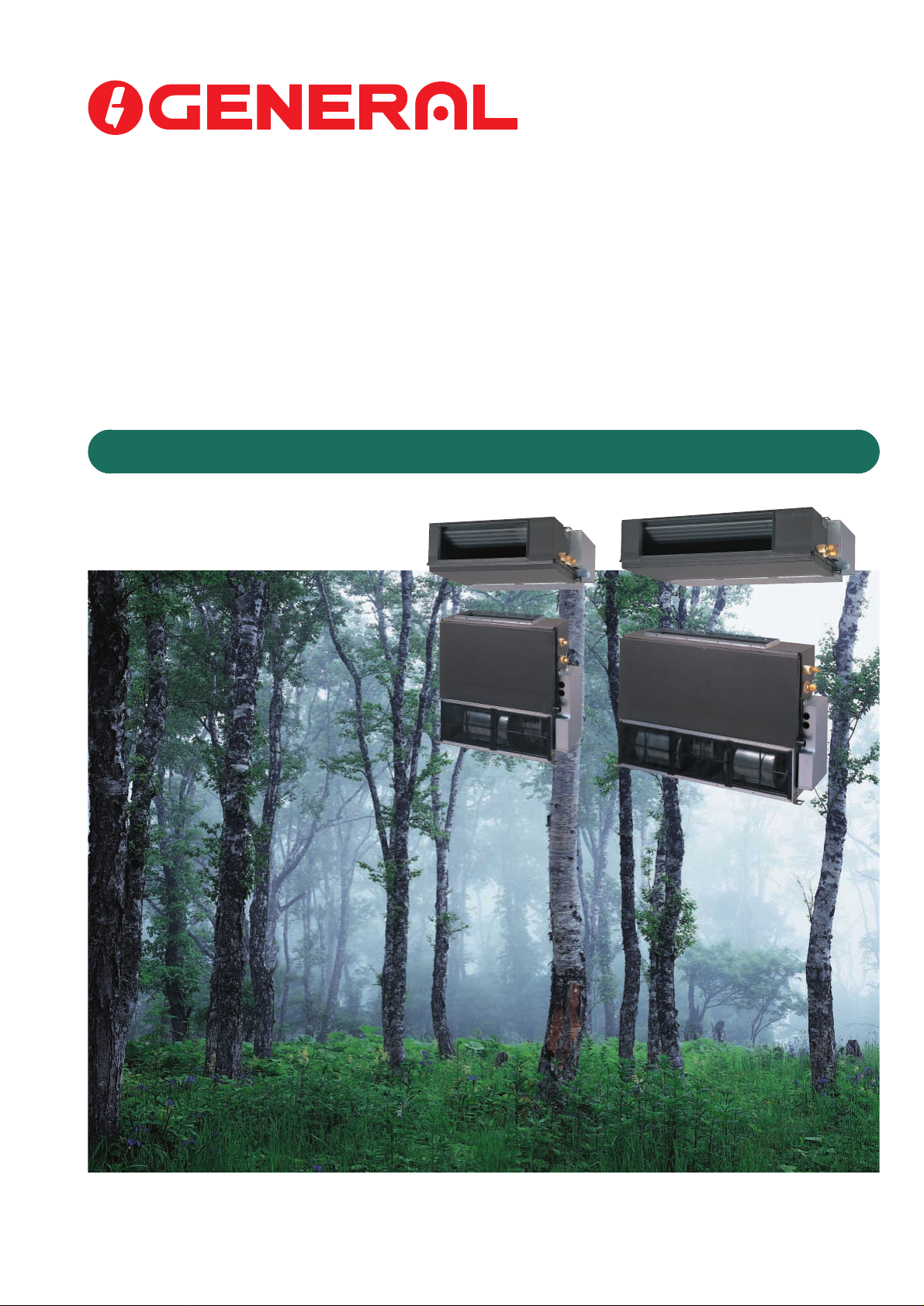
Easy to Install (Universal Type)
Ceiling concealed Floor standing concealed
Compact Design
• Ultra-thin duct air conditioner for easy installation
Dimensions (mm)
217
663
● Highly functional LCD wired remote controller (Refer to the next page for details.)
• Two remote controls for operation in different rooms
• Auto restart function in case of power failure
• Repeat timer can turn the unit on/off every day at the same time.
• Only preset air conditioners can be stopped by pressing the ZONE CONTROL b utton.
• Energy saving operation
ENERGY SAVE mode uses a computer program to economically control unit operation by raising the set temperature slightly in the cooling mode and lowering the set temperature in the heating mode. If you press the ENERGY SAVE button while the air conditioner is on, it will change to
595
217
953
595
the conservation mode. If you press the ENERGY SAVE button while the unit in the timer mode
(ON timer, PROGRAM timer or REPEAT timer), the unit will go into the conservation mode when
the unit starts with the timer.
● Low external air temperature cooling (A OG18R Model onl y)
• Cooling and heating operations capable with external air temperature down to 0°C.
● T r opical specifications (AOG18R Model only)
• Cooling operation capable with exter nal air temperature up to 52°C.
● Pipe length up to 20m with height differential up to 10m (AOG18R Model only)
– 2 –
Page 4
■
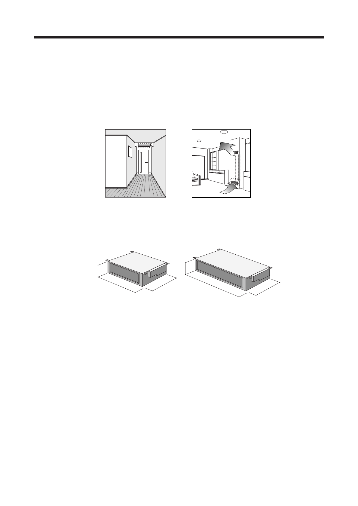
LIQUID CR YSTAL REMOTE CONTR OLLER
Remote Controller
Display
o !0 !1
i
NON STOP
OFF ON
TIMER
PROGRAM
REPEAT
TIMER
MODE
CLOCK ADJUST
CLOCK
OFF
ON
TIMER
ON
OFF
SET
TIMER
ENERGY
SAVE
CONTROL
TEMP.
SET
TEMP
ZONE
FAN AUTO
FAN HIGH
FAN MED
FAN LOW
FAN
CONTROL
HEAT
FAN
COOL
DEFROST TEST
CONTROL
yu
For explanatory purposes, the figure showing the remote controller display shows all possible displays.
The actual display shows only that area that is being
adjusted or used.
MASTER
ST AR T
STOP
qe wrt
q START/STOP Button
Press to start and stop operation.
!2
w Operation Lamp
Lights it during operation and when
the timer is on.
e ZONE CONTROL Button
Use to turn the zone control on and
off.
r ZONE CONTROL Lamp
Lights up when the unit is in the zone
control mode.
t ENERGY SAVE Button
Turns the energy efficient mode on
and off.
y ENERGY SAVE Lamp
Lights up when the unit is in the energy save mode.
u CLOCK ADJUST Button
i TIMER MODE Button
Use to change timer modes (NON
STOP, OFF TIMER, ON TIMER, PROGRAM TIMER, REPEAT TIMER).
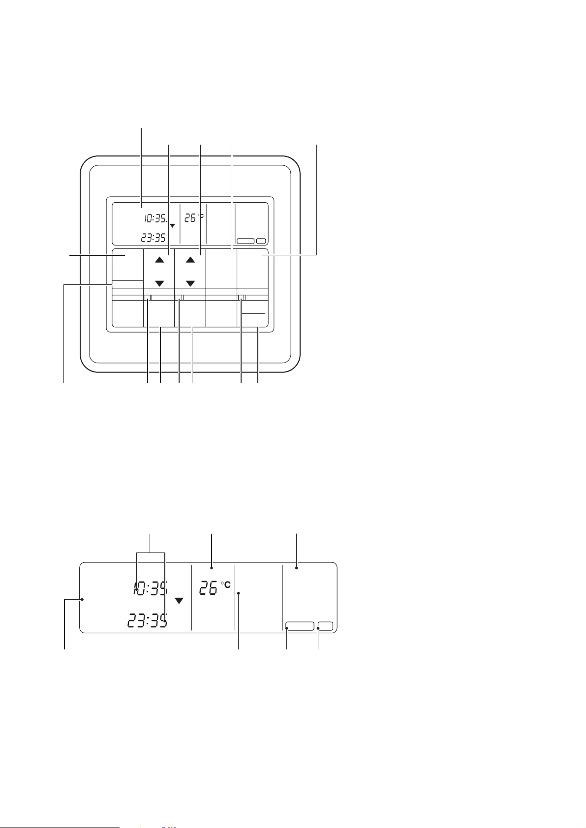
● Remote Controller Display
!3 !4 !5
NON STOP
OFF ON
TIMER
PROGRAM
REPEAT
CLOCK
TIMER
OFF
ON
ON
OFF
TEMP.
FAN AUTO
FAN HIGH
FAN MED
FAN LOW
!6
Depending on the usage circumstances of the unit (room size,
outdoor temperature etc.), the displayed temperature may differ
from the actual room temperature.
HEAT
FAN
COOL
DEFROST TEST
!9!8!7
o SET TIME Button (▲ / ▼)
Use to change the timer settings and
to set the current time.
!0 SET TEMP. Button (▲ / ▼)
Use to change the temperature setting.
!1 FAN CONTROL Button
Use to select the fan speed (AUTO,
HIGH, MED, LOW).
!2 MASTER CONTROL Button
Use to select the various operating
modes (HEAT, FAN, COOL).
!3 Clock Display (CLOCK/TIMER)
!4 Set Temperature Display (TEMP.)
!5 Operation Mode Display
!6 Timer Mode Display
!7 Fan Speed Display
!8 DEFROST Display
– 3 –
!9 TEST display
Page 5

2. OUTLINE AND DIMENSIONS
2.1 INDOOR UNIT
• MODELS : ARG7R / 9A / 9R
596
560
390
(Unit : mm)
663
630
400
150
• MODELS : ARG12R / 14R / 18RH
886
850
390
605
57520
217
150
600
953
920
605
57520
217
– 4 –
Page 6

2.2 OUTDOOR UNIT
• MODEL : AOG18R (Unit : mm)
643
333
25
840
804
336
• MODELS : AOG7R / 9R / 12R/ 14R
493
(Mounting bolt pitch)
750
517
13
250
285540
– 5 –
Page 7

3. PERFORMANCE DATA
3.1 PERFORMANCE CURVE
ARG18R / 18RH
130
120
110
100
90
Capacity (%)
80
70
60
Indoor
DB/WB (°C)
31/22.5
27/19
23/16.5
19/13
0510
15 20 25
COOLING
30 35 40 45 50 55
Outdoor (°C)
31/22.531/22.5
27/1927/19
23/16.523/16.5
19/13
19/13
Indoor
DB/WB (°C)
130
120
110
100
90
80
70
60
ARG18R / 18RH
130
120
110
100
Capacity (%)
90
80
70
Indoor
DB/WB (°C)
Total Input (%)
27
20
15
HEATING
0 5 10 15 20
Outdoor (°C)
Indoor
DB/WB (°C)
15
20
27
130
120
110
100
90
80
70
Total Input (%)
ARG7R / 9R / 12R / 14R
COOLING
130
120
110
100
90
Capacity (%)
80
70
60
31/22.5
Indoor
DB/WB (°C)
31/22.5
27/1927/19
23/16.523/16.5
19/1319/13
31/22.531/22.5
27/1927/19
23/16.523/16.5
19/13
19/13
Indoor
DB/WB (°C)
130
120
110
100
90
80
70
ARG7R / 9R / 12R / 14R
130
120
110
100
Capacity (%)
90
80
70
Indoor
DB/WB (°C)
Total Input (%)
27
20
15
HEATING
Indoor
DB/WB (°C)
15
20
27
130
120
110
100
90
80
Total Input (%)
0510
15 20 25
Outdoor (°C)
30 35 40 45 50 55
60
– 6 –
0 5 10 15 20
Outdoor (°C)
70
Page 8

3.2 FAN CURVE
ARG7R
Recommended range
56 83 111 139
(Pa)
50
40
30
20
10
EXTERNAL STATIC PRESSURE
0
200 300 400 500
HIGH
AIR FLOW
(l/sec)
(m
3
/h)
ARG9R
56 83 111 139
50
(Pa)
40
30
20
10
EXTERNAL STATIC PRESSURE
0
200 300 400 500
ARG14R ARG18RHARG18R
Recommended range
83 111 194167139
(Pa)
50
40
30
20
10
EXTERNAL STATIC PRESSURE
0
300 400 500 600 700
HIGH
AIR FLOW
(l/sec)
(m
3
/h)
139 167 194 222
(Pa)
50
40
30
20
10
EXTERNAL STATIC PRESSURE
0
500 600 700 800
Recommended range
HIGH
AIR FLOW
Recommended range
HIGH
AIR FLOW
(l/sec)
(m
(l/sec)
(m
3
/h)
3
/h)
ARG12R
(Pa)
(Pa)
Recommended range
83 111 194167139
50
40
30
20
10
EXTERNAL STATIC PRESSURE
0
300 400 500 600 700
139 167 194 222
80
70
60
50
40
EXTERNAL STATIC PRESSURE
30
500 600 700 800
HIGH
AIR FLOW
Recommended range
HIGH
AIR FLOW
(l/sec)
(m
(l/sec)
(m
3
/h)
3
/h)
3.3 CAPACITY BY AIR FLOW
6000
5500
5000
4500
4000
3500
Capacity (kW)
3000
2500
2000
1500
200 300 400 500 600 700 800
COOLING
ARG12R
ARG9A/ 9R
ARG7R
Air Flow (m
ARG18R/
18RH
ARG14R
3
/h)
3.4 OUTLET AIR TEMPERATURE
14
13
12
11
10
Temperature (°C)
9
8
200 300 400 600 700 800
COOLING
ARG7R
ARG9A /9R
ARG12R
Air Flow (m
ARG14R
ARG18R
/18RH
500
3
/h)
6000
5500
5000
4500
4000
3500
Capacity (kW)
3000
2500
2000
1500
200 300 400 500 600 700 800
ARG7R
ARG12R
ARG9R
Air Flow (m
3
/h)
ARG18R/
18RH
ARG14R
HEATING
48
47
46
45
44
HEATING
43
42
Temperature (°C)
41
40
39
200 300 400 500 600 700 800
ARG7R
ARG12R
ARG9R
Air Flow (m
ARG14R
3
/h)
ARG18R
/18RH
– 7 –
Page 9

3.5 TEMPERATURE RANGE
MODEL NO. OPERATION
ARG18R/18RH Approx. 0°C to 52°C
ARG14R
ARG12R COOLING Approx. 18°C to 32°C Approx. 21°C to 43°C
ARG9R/9A
ARG7R
ARG18R/18RH
ARG14R
ARG12R HEATING Approx. 30°C or less Approx. 0°C to 21°C
ARG9R
ARG7R
3.6 REFRIGERANT CHARGE
PIPE LENGTH 5m 7.5m 10m 15m 20m refrigerant
ARG7R
ARG9A
FULL
CHARGE
AMOUNT
ARG9R
ARG12R
ARG14R
ARG18R 1,650g 1,775g 2,025g 2,275g 50
/18RH (58.2oz) (62.6oz) (71.4oz) (80.2goz) (0.53)
1,000g 1,050g 1,150g
(35.3oz) (37.0oz) (40.6oz) (0.22)
950g
(33.5oz)
920g
(32.5oz)
950g
(33.5oz)
1,020g
(36.0oz)
Temperature Range
Indoor Unit Outdoor Unit
Additional
g/m (oz/ft)
––––– –––––
––––– –––––
––––– –––––
––––– –––––
–––––
20
• ARG7R/9A/9R/12R have a chargeless design.
• When the connection piping length exceeds 7.5m, the ARG14R/18R/18RH
require an additional charge of 20g/m (14R) and 50g/m(18R/18RH).
– 8 –
Page 10

4. SPECIFICATIONS
Model
Power Source
Capacity
Total Ampacity
Total Input
E.E.R.
Starting Current A 17 21 29 33 50
Fan Speed Med r.p.m. 630 880 610 740 900 1,220
Air
Circulation
Indoor Unit
Noise Med dB (A) 28 33 25 29 38 35
Fan Type x Q’ty Sirocco x 1 Sirocco x 2
Dimensions
H x W x D
Weights Net / Gross kg 18 / 22 25 / 29
Fan Speed r.p.m. 740
Air Circulation m3/h 1,600 2,590
Noise dB (A) 48 49 54
Fan Type x Q’ty Propeller x 1
Outdoor Unit
Dimensions
H x W x D
Weights Net / Gross kg 31 / 33 30 / 32 34 / 36 37 / 39 67 / 76
Refrigerant Charge kg 0.95 0.92 0.95 1.02 1.00 1.65
Pipe Size (Liquid / Gas) mm 6.35 / 9.53 6.35 / 12.7 9.53 / 15.88
Connection Method Flare
Pipe Length / Height m 15 / 8 20 / 8
Remote Controller Cable Length L.C.D. Wired (10m)
Static Pressure Pa 0 (max. 40) 40 (max. 70)
Operation Range
Indoor Unit ARG7RLB ARG9ALB ARG9RLB ARG12RLB ARG14RLB ARG18RLB ARG18RLBH
Outdoor Unit AOG7RGA AOG9AGA AOG9RGA AOG12RGA AOG14RGA AOG18RZDL
/Hz 1 / 50
V 220 - 240
Cooling
Heating
Cooling
Heating 3.4 - 3.3 ––– 4.1 - 3.9 5.7 - 5.5 6.9 - 7.0 8.3 - 8.2
Cooling
Heating 0.72 - 0.75 ––– 0.87 - 0.92 1.25 - 1.30 1.47 - 1.54 1.80 - 1.90
Cooling
Heating 3.33 -3.27 ––– 3.45 - 3.37 3.20 - 3.15 3.20 - 3.10 3.06 - 2.95
High 680 960 640 840 960 1,310
Low 580 810 580 650 840 1,120
High 340 420 460 640 750
Med m3/h 320 390 430 560 700
Low 290 360 390 480 640
High 31 35 26 32 39 36
Low 26 31 24 26 36 33
Net
Gross 324 x 785 x 686 324 x 1,075 x 686
Net
Gross 609 x 882 x 339 750 x 959 x 429
Cooling
Heating In : 16 - 30, Out : 0 - 21
kW 2.10 - 2.15 2.70 - 2.80 2.60 - 2.70 3.40 - 3.50 3.90 - 4.00 5.20 - 5.30
BTU/h 7,150 - 7,350 9,200 - 9,500 8,900 - 9,200 11,300 - 11,600 13,300- 13,700 17,800 - 18,100
kW 2.40 - 2.45 ––– 3.00 -3.10 4.00 - 4.10 4.70 - 4.80 5.50 - 5.60
BTU/h 8,200 - 8,350 ––– 10,200 - 10,600 13,700 - 14,000 16,000- 16,400 18,800 - 19,100
3.6 - 3.5 4.3 - 4.2 4.1 - 3.9 5.5 - 5.3 7.1 - 7.2 9.4 - 9.2
A
0.76 - 0.80 0.93 - 0.97 0.87 - 0.92 1.20 - 1.25 1.50 - 1.60 2.05 - 2.15
kW
kW/kW
2.76 - 2.69 2.90 - 2.89 2.99 - 2.94 2.83 - 2.80 2.60 - 2.50 2.54 - 2.47
mm
mm
°C
217 x 663 x 595 217 x 953 x 595
530 x 750 x 250 643 x 840 x 336
In : 18 - 32, Out : 21 - 43 In : 18 - 32, Out : 0 -52
– 9 –
Page 11

0009J-906-1739
September 2000 Printed in Japan
 Loading...