

Page 1
R410A
2 . DUCT TYPE
AR 7 - 9FUAB, AR 12 - 18FUAD
AR 7 - 9UUAB, AR 12 - 18UUAD
D2D_AR006E/06
2007.07.26
Page 2
2-1. FEATURE
MODELS :
AR 7FUAB / AO 7FSAJ
AR 9FUAB / AO 9FSAJ
AR 12FUAD / AO 12FSAJ
AR 14FUAD / AO 14FSDJ
AR 18FUAD / AO 18FNDK , AO 18FNDN
DUCT TYPE
AR7 - AR18K
AR 7UUAB / AO 7USAJL
AR 9UUAB / AO 9USAJL
AR 12UUAD / AO 12USAJL
AR 14UUAD / AO 14USDJL
AR 18UUAD / AO 18UNDKL , AO 18UNDNL
FEATURES
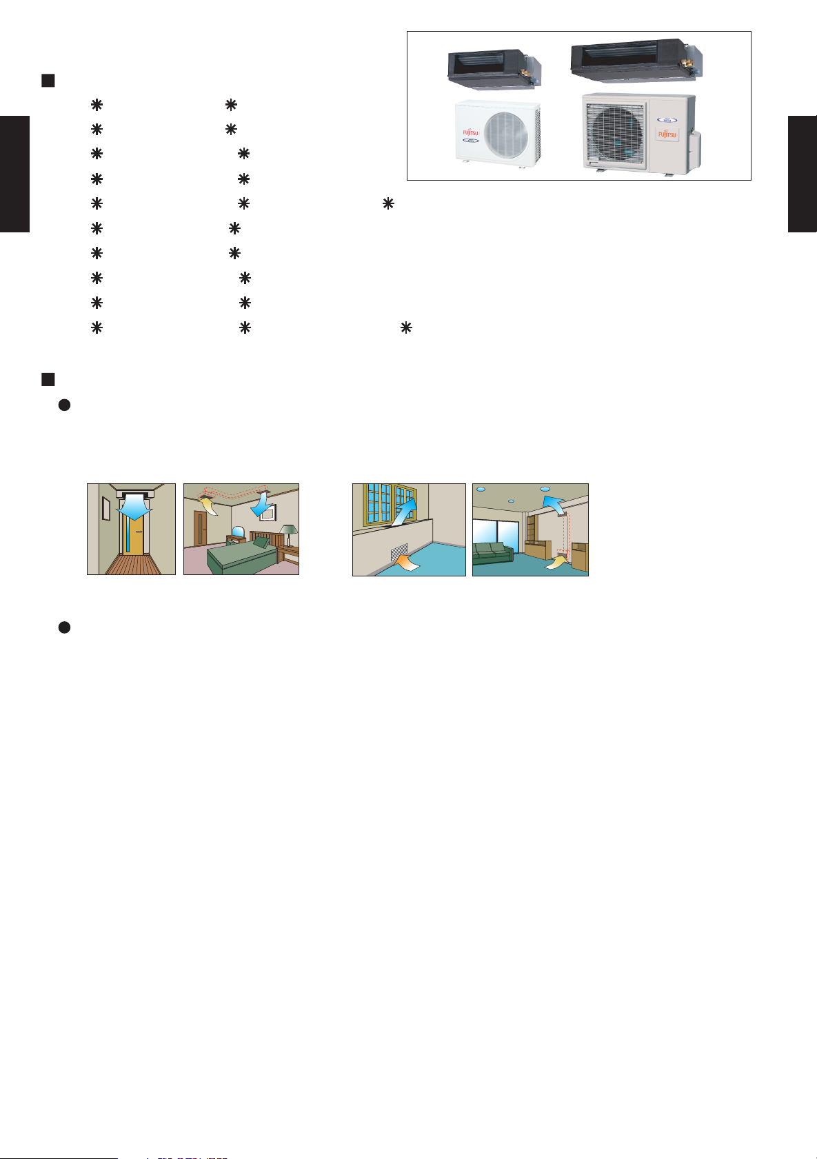
Universal design indoor unit
Since vertical and horizontal installation is possible, and the intake direction can also be selected
from two directions, flexible installation is possible.
DUCT TYPE
AR7 - AR18K
Ceiling concealed Floor concealed
Thin and compact indoor unit
- (02 - 01) -
Page 3
2-2. REMOTE CONTROLLER
2-2-1. WIRED REMOTE CONTROLLER
FEATURES
Various timer setup (ON / OFF / WEEKLY) are possible.
Equipped with weekly timer as standard function.
(2 times Start / Stop per day for a week)
SUMOTUWETH FR SA
7
3126 9
15 18 21
DUCT TYPE
AR7 - AR18K
When setting up a timer, operation mode and a temperature
setup can be changed.
When a failure occurs,the error code is displayed. (Maximum of 16)
DUCT TYPE
AR7 - AR18K
Error indication.(A maximum of 16 error histories are memorizable.)
Up to 16 indoor units can be simultaneously controlled.
Anti freeze and energy saving operation are possible.
Easy installation with a slim shape with no boldge in the back.
The room temperature can be controlled by being detected the temperature
accurately with built-in thermo sensor.
High performance and compact size
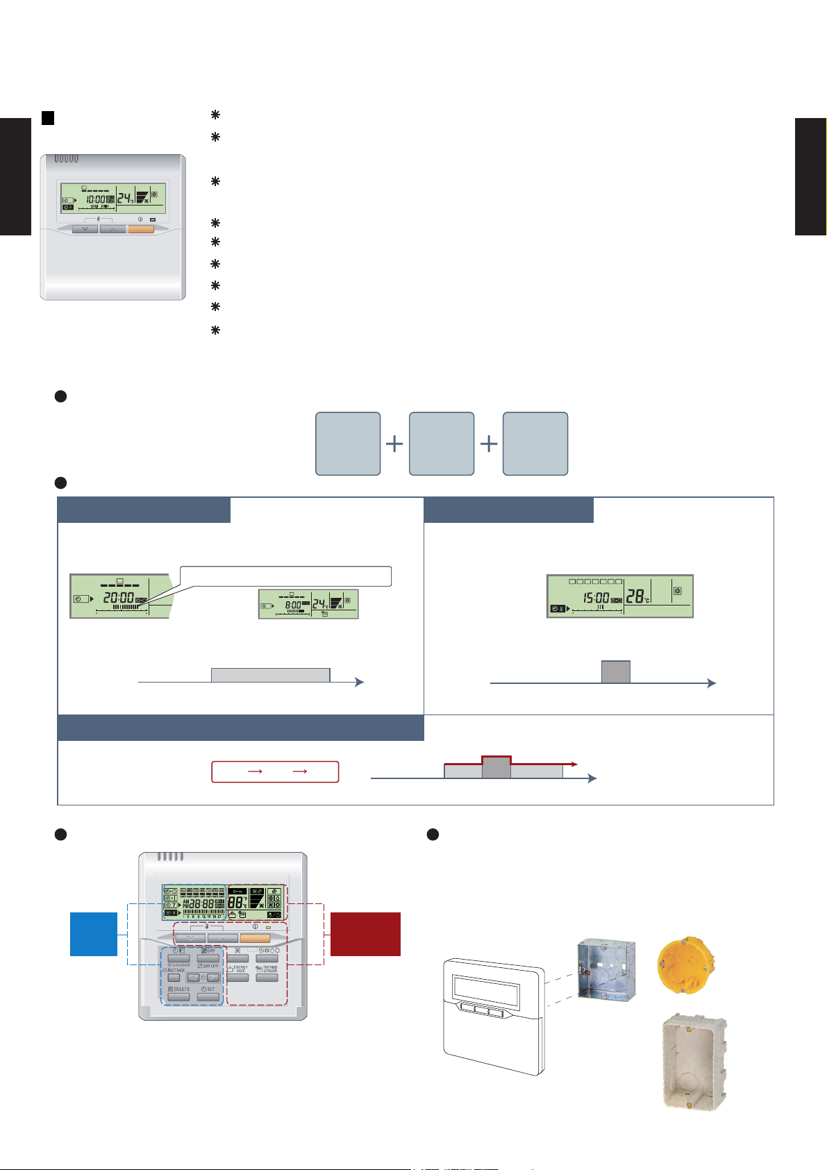
Three functions are combined in
one unit.
Wired
remote
controller
Weekly
timer
Setback
timer
Built-in timers
Setback timerWeekly timer
Possible to set ON/OFF time to operate twice each day
of the week.
SUMOTUWETH FR SA
7
3126 9
15 18 21
Setup screen example
(Set to Wednesday: 8:00 to 20:00.)
0 3 6 9 12 15 18 21 Time
Easy-to-understand time bar display
24°C
SUMOTUWETH FR SA
7
3126 9
15 1821
Screen
after setup
Possible to set temperature for two time spans and
for each day of the week.
SUMOTUWETH FR SA
3126 9
Setup screen example
(Set from Sunday to Saturday: 12:00 to 15:00, 28 °C.)
0 3 6 9 12 15 18 21 Time
At "Weekly timer" + "Set back timer" setup
24°C
24°C 28°C 24°C
0 3 6 9 12 15 18 21 Time
28°C
Easy-to-understand operation Simple installation
Components are compatible with standard
switch boxes. Flat back construction allows
equipment to be installed wherever it is
Timer
area
Operation
area
needed.
15 18 21
28°C
[
Variable timer control
]
The operation/display sections are zoned according to time and operation, enabling variable programming to match application.
- (02 - 02) -
European
switch box
JIS box
Page 4
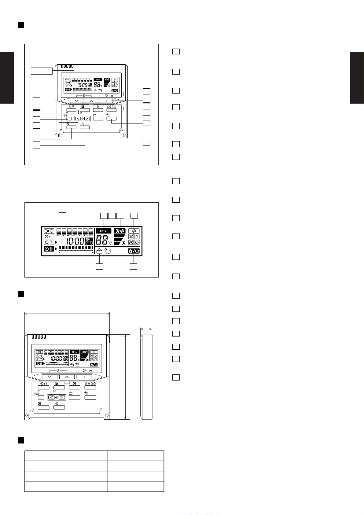
FUNCTIONS
1
START/STOP button
Pressed to start and stop operation.
Display
SUMOTUWETH FR
SA
369
12 15 18 21
DUCT TYPE
AR7 - AR18K
10
2
7
8
9
CLOCK ADJUST
SET BACK
DELETE SET
DAY
DAY OFF
ENERGY
SAVE
THERMO
SENSOR
13
1
3
4
6
2
Set temperature button
Selects the setting temperature.
3
Master control button
Selects the operating mode(AUTO, HEAT, FAN, COOL, DRY).
4
Fan control button
Selects the fan speed (AUTO, LOW, MED, HIGH).
5
Energy save button
DUCT TYPE
AR7 - AR18K
Turns the energy efficient mode on and off.
11
12
5
6
Thermo sensor
7
Timer mode (CLOCK ADJUST) button
Selects the timer mode (OFF TIMER, ON TIMER, WEEKLY TIMER)
Set the current time.
8
Day (DAY OFF) button
Display panel
Temporarily cancels of one day timer.
9
Set back button
pressed select the set back timer.
14
15
1617 18
10
Set time button
Pessed to select the set back timer.
SUMOTUWETH FR
SA
11
Delete button
The schedule of a weekly timer is deleted.
369
12 15 18 21
1920
12
Set button
Sets the date, hour, minute and on-off time.
13
Operation lamp
Lights during operation and when the timer is on.
DIMENSION
[ Unit : mm ]
17
120
SUMOTUWETH FR
369
12 15 18 21
DAY
CLOCK ADJUST
DAY OFF
SET BACK
DELETE SET
Front View
120
SA
ENERGY
THERMO
SAVE
SENSOR
SPECIFICATION
SIZE (H x W x D mm) 120 x 120 x 17
WEIGHT ( g ) 160
CABLE LENGTH ( m )
POWER ( V )
10
12
14
Timer and clock display
15
Operation mode display
16
Fan speed display
17
Central control display
18
Temperature display
19
Stand by display
Indicates during the oil recovery and defrosting operation.
20
Energy save display
- (02 - 03) -
Page 5
2-3. SPECIFICATIONS
TYPE
MODEL NAME
POWER SOURCE
EUROPEAN ENERGY LABEL
CAPACITY
INPUT POWER
DUCT TYPE
AR7 - AR18K
CURRENT A
STARTING CURRENT
EER
COP
MOISTURE REMOVAL
AIR
CIRCULATION
RECOMMENDED STATIC PRESSURE
FAN TYPE x Q'ty
FAN MOTOR OUTPUT W
NOISE LEVEL
(SOUND
PRESSURE)
COOL/HEAT
COMPRESSOR
COOLING
HEATING
COOLING RATED 0.76 0.99 1.24 1.39 2.03
HEATING RATED - - - - -
COOLING RATED 3.7 4.6 5.5 6.3 9.0
HEATING RATED - - - - -
INDOOR
OUTDOOR
INDOOR
OUTDOOR
TYPE
OUTPUT
STARTING METHOD
Coil
INDOOR
HEAT
EXCHANGER
TYPE
OUTDOOR
SAFETY DEVICES
CASING COLOR
INDOOR 217 x 663 x 595 217 x 663 x 595 217 x 953 x 595 217 x 953 x 595 217 x 953 x 595
DIMENSIONS
H ×W ×D
WEIGHT
PIPE
REFRIGERANT
REFRIGERANT OIL
OPERATION(OUTDOOR)
REMOTE CONTROLLER
OUTDOOR 530 × 750 × 250 530 x 750 x 250 530 x 750 x 250 530 x 750 x 250 650 x 830 x 320
INDOOR 324 × 785 × 686 324 x 785 x 686 324 x 785 x 686 324 x 785 x 686 324 x 785 x 686
OUTDOOR 609 × 882 × 339 609 x 882 x 339 609 x 882 x 339 609 x 882 x 339 743 x 984 x 413
INDOOR 18/22 18/22 25/29 25/29 25/29
OUTDOOR 27/29 27/29 34/36 35/37 52/56
CONNECTION METHOD
SIZE
MAX LENGTH
MAX HEIGHT
fin
Rows x Stages x
Fin Pitch
Coil Dimensions mm
Coil
fin
Rows x Stages x
Fin Pitch
Coil Dimensions mm
INDOOR
OUTDOOR
INDOOR
OUTDOOR
NET
GROSS
NET /
GROSS
LIQUID
GAS
TYPE
CHARGE kg 0.55 0.60 0.80 0.90 0.90
TYPE
COOLING
HEATING
MATERIAL
DRAIN PIPE
SIZE
INDOOR
OUTDOOR
RATED
RATED
COOLING 2.83 2.83 2.82 3.02 2.66
HEATING - - - - -
High 340 420 500 640 1000
Med 320 390 450 560 900
Low 300 360 400 480 760
INDOOR Sirocco x 1 Sirocco x 1 Sirocco x 2 Sirocco x 2 Sirocco x 2
OUTDOOR Propeller x 1 Propeller x 1 Propeller x 1 Propeller x 1 Propeller x 1
INDOOR 13 13 45 45 45
OUTDOOR 22 22 22 22 65
High 31.00 35.00 29.00 34.00 43.00
Med 28.00 33.00 28.00 32.00 40.00
Low 26.00 31.00 27.00 30.00 36.00
DUCTED MODELS
AR*7FUAB AR*9FUAB AR*12FUAD AR*14FUAD AR*18FUAD
AO*7FSAJ AO*9FSAJ AO*12FSAJ AO*14FSDJ AO*18FNDK
COOLING C C C B D
kW 2.15 2.80 3.50 4.20 5.40
BTU/h 7300 9500 11900 14300 18400
kW - - - - -
BTU/h - - - - -
kW
A 19.5 21 30 31 39
kW/kW
l/h (pints/h) 0.8(1.7) 1.0(2.1) 1.2(3.2) 1.5(3.2) 1.6(3.4)
m3/h
Pa 0(0-20,20-40) 0(0-20,20-40) 0(0-20,20-40) 0(0-20,20-40) 0(0to70)
dB(A)
mm
mm
mm
kg(lbs)
mm
m 15 15 15 15 20
m 8 8 8 8 8
℃
mm
1600 1600 1600 1600 3200
48.00 48.00 49.00 48.00 52.00
700 900 1075 1150 1500
2x14x1.30 2x14x1.30 2x14x1.30 2x14x1.30 2x14x1.30
294×410×26.6 294x410x26.6 294x700x26.6 294x700x26.6 294x700x26.6
1×24×1.45 1x24x1.45 2x24x1.45 2x24x1.45 1x30x1.30
504×770×18.19 504x770x18.19 504x658x36.38 504x658x36.38 630x905x18.19
(
1/4 inc.)
6.35
9.52(3/8 inc.) 9.52(3/8 inc.) 9.52(3/8 inc.) 12.7(1/2 inc.) 15.88(5/8 inc.)
6.35(1/4 inc.) 6.35(1/4 inc.) 6.35(1/4 inc.) 6.35(1/4 inc.)
COOLING ONLY TYPE
230V〜 50Hz
ROTARY
Permanent Starting Condenser
Copper tube
Aluminum
Copper tube
Aluminum
Fan motor thermal protector,Fuse
Fan motor thermal protector,Fuse
Hot-dipped galvanized steel sheet
Beige(10YR7.5/1.0NN)
FLARE
R410A
POE
21 to 43
-
WIRED(AR-3TA1)
ABS
Outer diameter 26.0mm
/ Inner diameter 21.5mm
DUCT TYPE
AR7 - AR18K
OPTIONS
INDOOR
OUTDOOR
Simple Wired Remocon(Fujitsu:UTB-YPB,General:UTB-GPB)
Note: Specifications are based on the following conditions.
Cooling: Indoor temperature of 27°CDB / 19°CWB,and outdoor temperature of 35°CDB/24°CWB.
Heating: Indoor temperature of 20°CDB / 15°CWB,and outdoor temperature of 7°CDB/6°CWB.
Standard static pressure : 0 Pa.
Pipe length : 7.5 m, Height difference : 0 m.(Outdoor unit - Indoor unit)
- (02 - 04) -
Page 6
AR 7UUAB AR 9UUAB AR 12UUAD AR 14UUAD AR 18UUAD
AO 7USAJL AO 9USAJL AO 12USAJL AO 14USDJL AO 18UNDKL
kW 2.15 2.70 3.50 4.00 5.40
Rows x Stages mm
Fin Pitch
Rows x Stages mm 1 x 24 2 x 24 2 x 24 2 x 24 2 x 30
Fin Pitch 1.45 1.45 1.45 1.45 1.45
6.35(1/4 inc.) 6.35(1/4 inc.) 6.35(1/4 inc.) 6.35(1/4 inc.) 6.35(1/4 inc.)
9.52(3/8 inc.) 9.52(3/8 inc.) 9.52(3/8 inc.) 12.7(1/2 inc.) 15.88(5/8 inc.)
-
Simple Wired Remocon(Fujitsu:UTB-YPB,General:UTB-GPB)
-6 to 24
ABS
Outer diameter 26.0
Inner diameter 21.5
WIRED(AR-3TA2)
FLARE
0 to 43
R410A
Aluminum
Aluminum
Copper tube
POE
Fan motor thermal protector,Fuse
Hot-dipped galvanized steel sheet
Fan motor thermal protector,Fuse
Beige(10YR7.5/1.0NN)
230V 50Hz
Copper tube
Permanent Starting Condenser
ROTARY
2 x 14
1.30
WEIGHT
INDOOR
NET /
GROSS
CASING COLOR
DIMENSIONS
H × W × D
OUTDOOR
Coil
mm
kg
RECOMMENDED STATIC PRESSURE
NOISE LEVEL
(SOUND
PRESSURE)
COOL/HEAT
OUTDOOR
Fin
Coil
FAN MOTOR OUTPUT
W
FAN TYPE x Q'ty
OUTPUT
REVERSE CYCLE TYPE
INDOOR
MODEL NAME
OUTDOOR
DUCTED MODELS
TYPE
kW/kW
INDOOR
MOISTURE REMOVAL
m3/h
OUTDOOR
AIR
CIRCULATION
COP
EER
POWER SOURCE
STARTING CURRENT
COOLING
HEATING
CAPACITY
RATED
RATED
kW
INPUT POWER
CURRENT
TYPE
COMPRESSOR
INDOOR
dB(A)
STARTING METHOD
A
OUTDOOR
mm
OPTIONS
MAX LENGTH
REMOTE CONTROLLER
DRAIN PIPE
MATERIAL
REFRIGERANT
INDOOR
NET
GROSS
HEAT
EXCHANGER
TYPE
Fin
SAFETY DEVICES
REFRIGERANT OIL
SIZE
TYPE
PIPE
MAX HEIGHT
CONNECTION METHOD
OPERATION(OUTDOOR)
°C
TYPE
SIZE
BTU/h 7300 9200 11900 13700 18400
kW 2.45 3.10 4.00 4.70 6.00
COOLING RATED 0.76 0.96 1.24 1.42 1.92
HEATING RATED 0.76 0.96 1.21 1.35 1.87
COOLING RATED 3.60 4.40 5.50 6.3 8.8
DUCT TYPE
AR7 - AR18K
HEATING RATED 3.60 4.50 5.40 6.0 8.7
COOLING 2.83 2.81 2.82 2.82 2.81
HEATING 3.22 3.23 3.31 3.48 3.21
High 340 420 500 640 1000
Med 320 390 450 560 900
Low 300 360 400 480 760
INDOOR Sirocco x 1 Sirocco x 1 Sirocco x 2 Sirocco x 2 Sirocco x 2
OUTDOOR Propeller x 1 Propeller x 1 Propeller x 1 Propeller x 1 Propeller x 1
INDOOR 13 13 45 45 45
OUTDOOR 22 22 22 22 65
High 31.0/31.0 35.0/36.0 29.0/30.0 34.0/34.0 43.0/43.0
Med 28.0/28.0 33.0/35.0 28.0/29.0 32.0/32.0 40.0/40.0
Low 26.0/26.0 31.0/34.0 27.0/28.0 30.0/30.0 36.0/36.0
BTU/h 8400 10600 13600 16000 20500
A 19.5 21 30 31 39
l/h (pints/h) 0.8(1.7) 1.0(2.1) 1.2(3.2) 1.5(3.2) 1.6(3.4)
1600 1600 1600 1600 3200
Pa 0(0-20,20-40) 0( 0-20,20-40) 0(0-20,20-40) 0(0-20,20-40) 0(0to70)
48.0/48.0 48.0/50.0 49.0/50.0 49.0/50.0 52.0/53.0
700 900 1075 1150 1500
DUCT TYPE
AR7 - AR18K
Coil Dimensions mm 294 x 410 x 26.6 294 x 410 x 26.6 294 x 700 x 26.6 294 x 700 x 26.6 294 x 700 x 26.6
mm
mm
Coil Dimensions mm 504 x 770 x 18.19 504 x 658 x 36.38 504 x 658 x 36.38 504 x 658 x 36.38 630 x 901 x 36.38
INDOOR
OUTDOOR
INDOOR
OUTDOOR
INDOOR 217 x 663 x 595 217 x 663 x 595 217 x 953 x 595 217 x 953 x 595 217 x 953 x 595
OUTDOOR 530 x 750 x 250 530 x 750 x 250 530 x 750 x 250 530 x 750 x 250 650 x 830 x 320
INDOOR 324 x 785 x 686 324 x 785 x 686 324 x 1075 x 686 324 x 1075 x 686 324 x 1075 x 686
OUTDOOR 609 x 882 x 339 609 x 882 x 339 609 x 882 x 339 609 x 882 x 339 743 x 984 x 413
INDOOR 18/22 18/22 25/29 25/29 25/29
OUTDOOR 28/30 30/32 34/36 35/37 52/56
LIQUID
GAS
CHARGE kg 0.65 0.75 0.85 1.00 1.40
COOLING
HEATING
m 15 15 15 15 20
m 8 8 8 8 8
mm
Note: Specifications are based on the following conditions.
Cooling: Indoor temperature of 27°CDB / 19°CW B,and outdoor temperature of 35°CDB/24°CWB.
Heating: Indoor temperature of 20°CDB / 15°CWB,and outdoor temperature of 7°CDB/6°CW B.
Standard static pressure : 0 Pa.
Pipe length : 7.5 m, Height difference : 0 m.(Outdoor unit - Indoor unit)
- (02 - 05) -
Page 7
2-4. DIMENSIONS
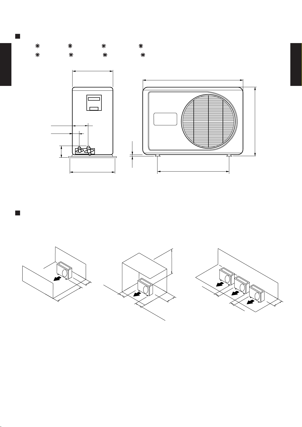
2-4-1. OUTDOOR UNIT
MODELS :
AO 7F , AO 9F , AO 12F , AO 14F
AO 7U , AO 9U , AO 12U , AO 14U
250
250
250
250
750
750
750
750
DUCT TYPE
AR7 - AR18K
100
100
100
100
60
60
60
60
13
13
13
95
95
95
95
285
285
285
285
13
540
540
540
540
(Unit : mm)
530
530
530
530
DUCT TYPE
AR7 - AR18K
Side view Front view
MOUNTING POSITION
When there are obstacles at
the back or front sides.
AIR
600 mm
or more
100 mm
or more
When there are obstacles at
the back, side(s), and top.
600 mm
(
Ser
v
or
i
c
mor
e
s
pac
e)
AIR
e
100 mm
or
mor
e
600 mm or more
300 mm
or more
When there are obstacles at the
back, side with the installation of
more than one unit.
AIR
600 mm
or more
600 mm
or more
300 mm
or more
- (02 - 06) -
Page 8
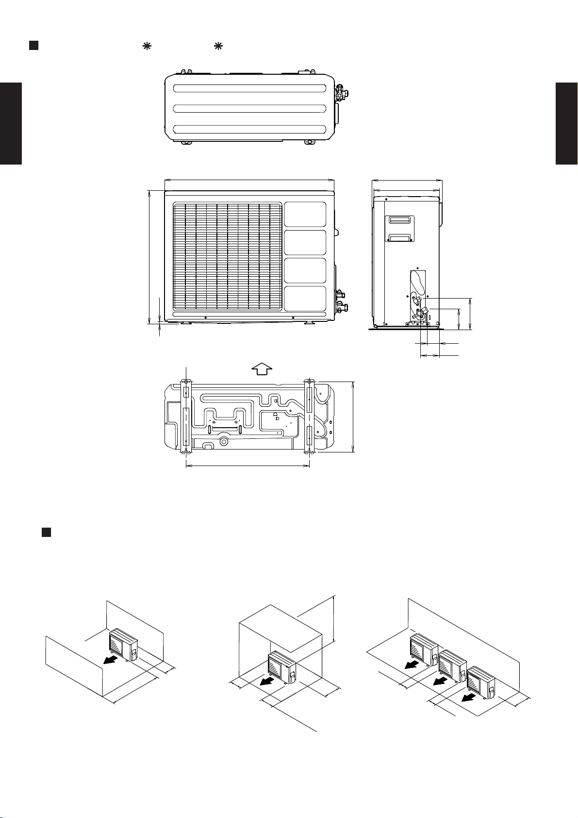
MODELS : AO 18F , AO 18U
AR7 - AR18K
830
650
12
Front view
Bottom
Air flow
343
350
320
Side view
154
101
58
90
DUCT TYPE
AR7 - AR18K
DUCT TYPE
Top view
MOUNTING POSITION
When there are obstacles at the
back or front sides.
AIR
600 mm
or more
100 mm
or more
603
Bottom view
When there are obstacles at the
back, side(s), and top.
600 mm or more
100 mm
or more
AIR
250 mm
(
Ser
300 mm
or more
v
o
i
c
r
m
e
s
o
pace)
r
e
When there are obstacles at the
back, side with the installation of
more than one unit.
AIR
250 mm
or more
250 mm
or more
300 mm
or more
- (02 - 07) -
Page 9
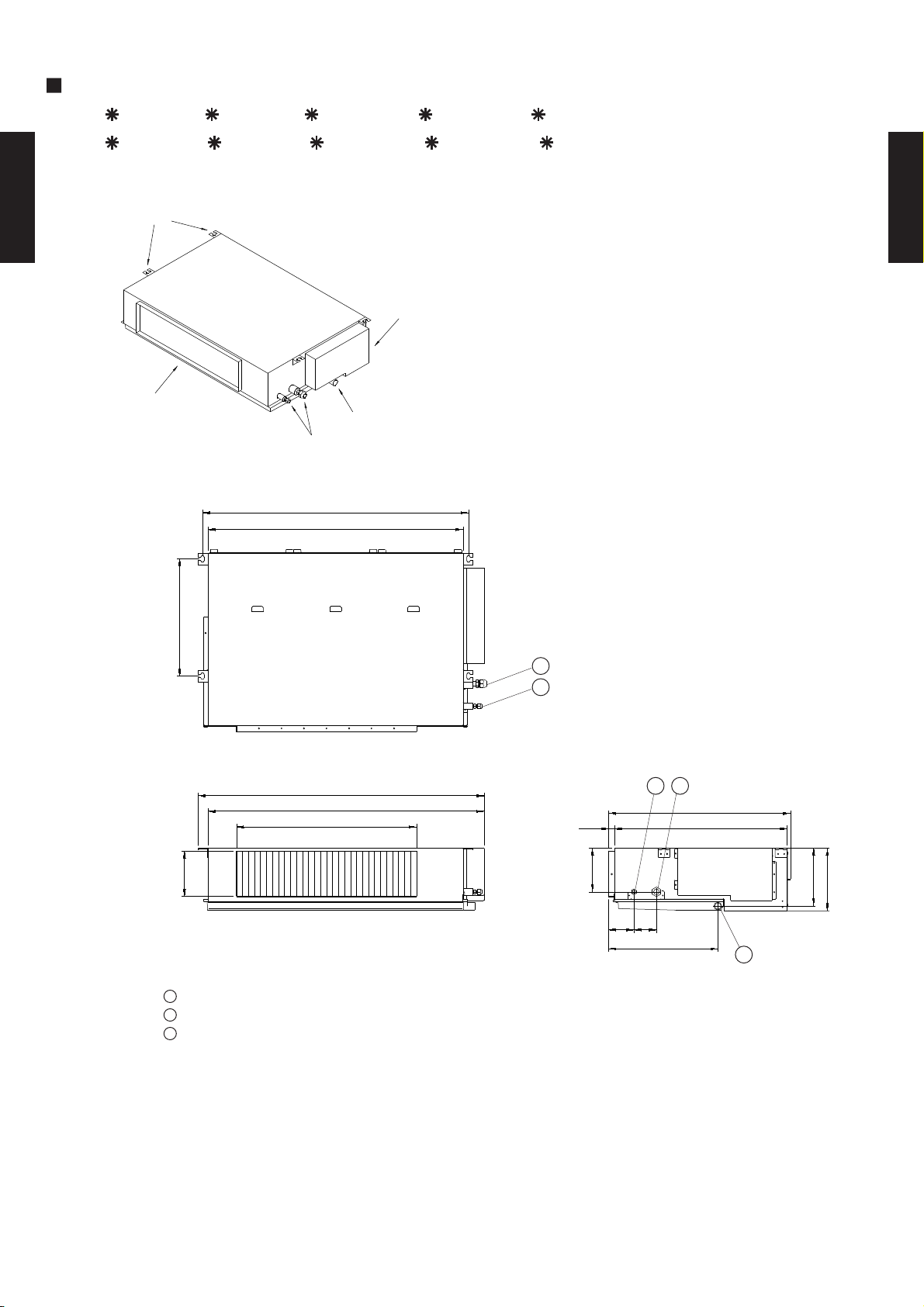
2-4-2. INDOOR UNIT
MODELS :
AR 7F , AR 9F , AR 12F , AR 14F , AR 18F
AR 7U , AR 9U , AR 12U , AR 14U , AR 18U
BRACKETS
( ) : AR7, AR9
DUCT TYPE
AR7 - AR18K
CONTROL BOX
AIR FLOW OUTLET
DRAIN PORT(Ø25.4)
COUPLING PIPE ASSY
886(596)
850(560)
390
(Unit : mm)
DUCT TYPE
AR7 - AR18K
1
2
Top view
953(663)
920(630)
600(400)
150
Front view
1
Refrigerant piping flare connection (Gas)
2
Refrigerant piping flare connection (Liquid)
3
Drain piping connection (Drain pipe : I.D. Ø21.5 O.D. Ø26.0)
150
85 75
Side view
364
12
605
57520
194
217
3
- (02 - 08) -
Page 10
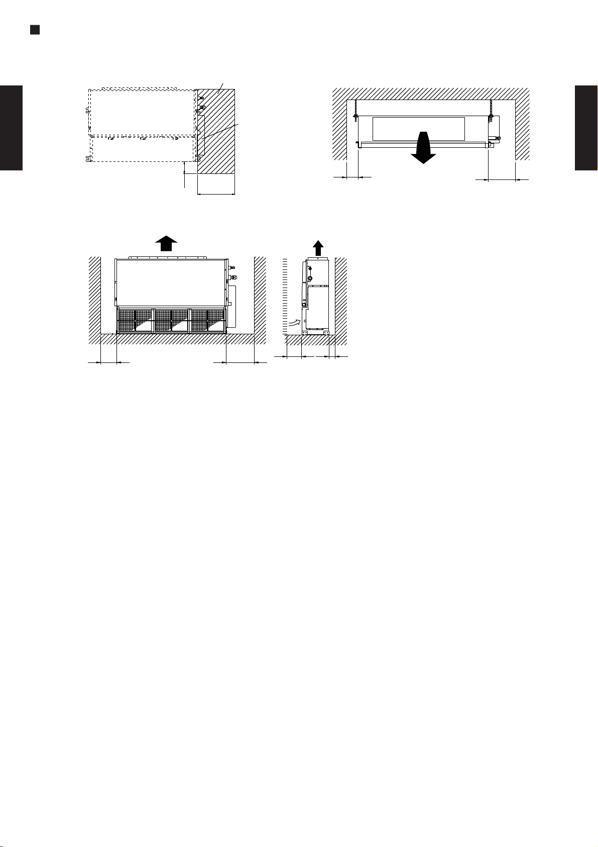
MOUNTING POSITION
Service hole
Unit
DUCT TYPE
AR7 - AR18K
300mm
100mm
Left
side
Strong and durable floor
100mm
or more
or more
or more
Control box
Right side
(PIPE side)
300mm
or more
30mm
or more
Left
side
100mm
or more
30mm
or more
Strong and durable ceiling
Indoor unit
300mm
or more
Right
side
DUCT TYPE
AR7 - AR18K
- (02 - 09) -
Page 11
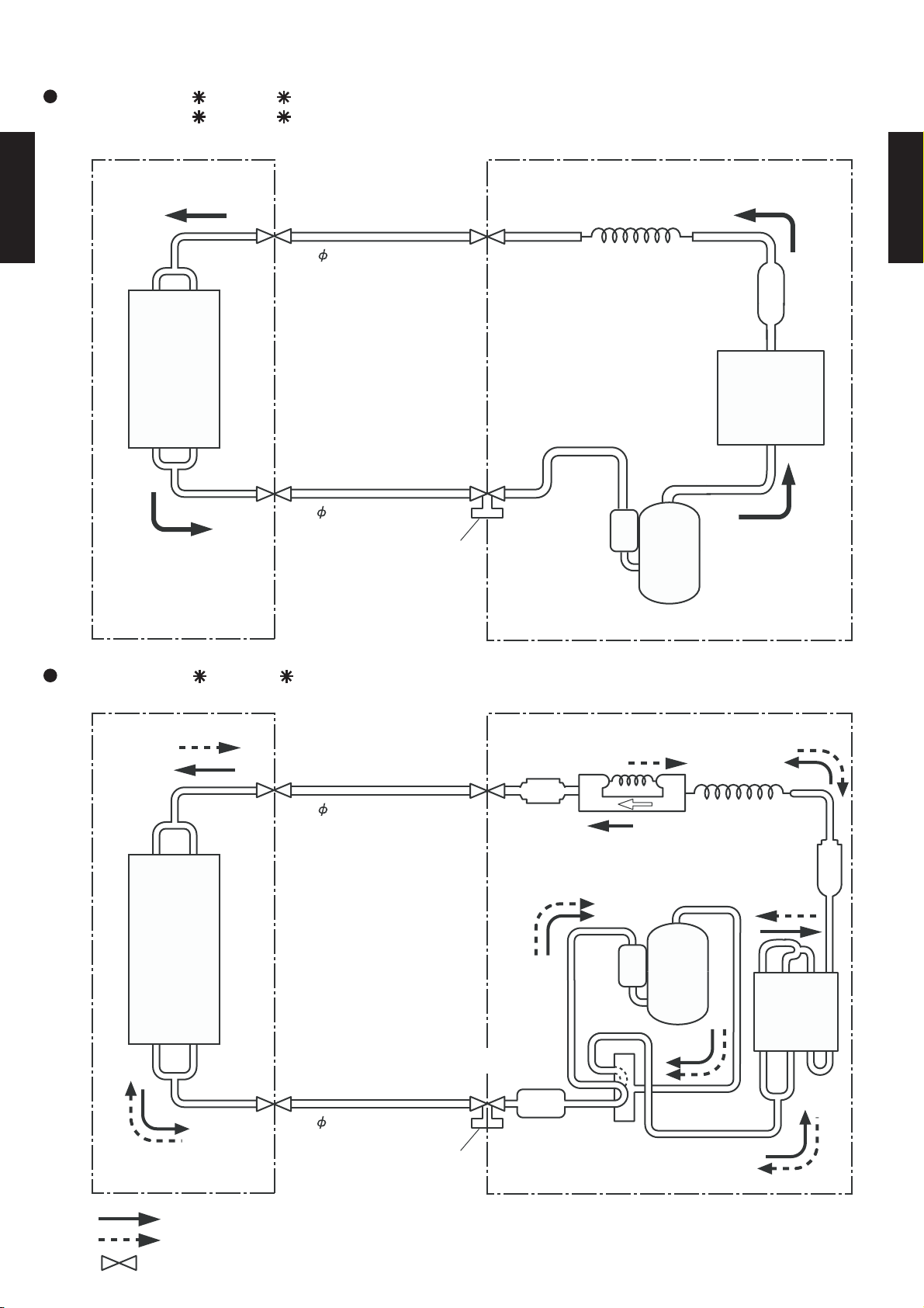
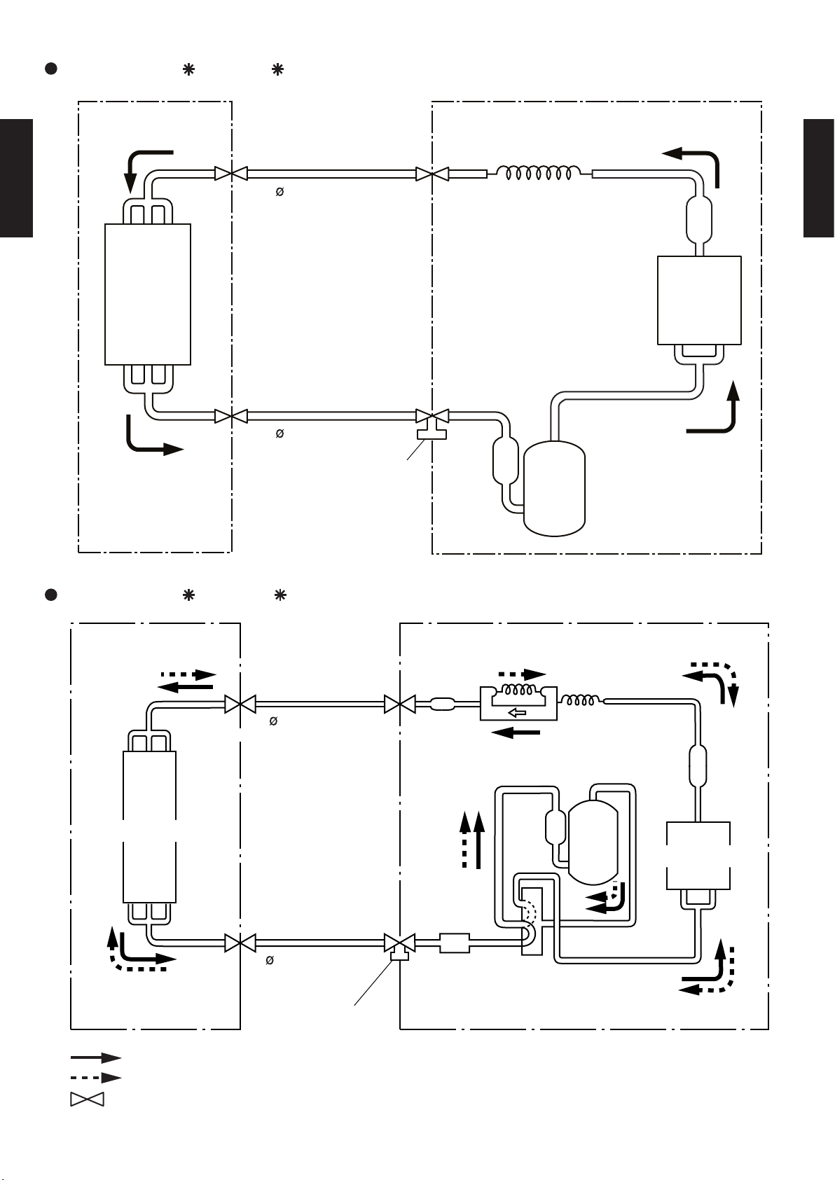
Refrigerant pipe
9.52 mm (3/8")
Refrigerant pipe
6.35 mm (1/4")
Capillary tube
Charging valve
3-Way
valve
Strainer
OUTDOOR UNITINDOOR UNIT
Condenser
Evaporator
Compressor
Refrigerant pipe
9.52 mm (3/8")
Refrigerant pipe
6.35 mm (1/4")
Capillary tube
Charging valve
OUTDOOR UNITINDOOR UNIT
Evaporator
Strainer
Strainer
4-Way
valve
Compressor
Muffler
Condenser
Cooling
Heating
: Flare coupling
2-5. REFRIGERANT CIRCUIT
MODELS :
DUCT TYPE
AR7 - AR18K
AR 7F / AO 7F
AR 9F / AO 9F
DUCT TYPE
AR7 - AR18K
MODELS :
AR 7U / AO 7U
- (02 - 10) -
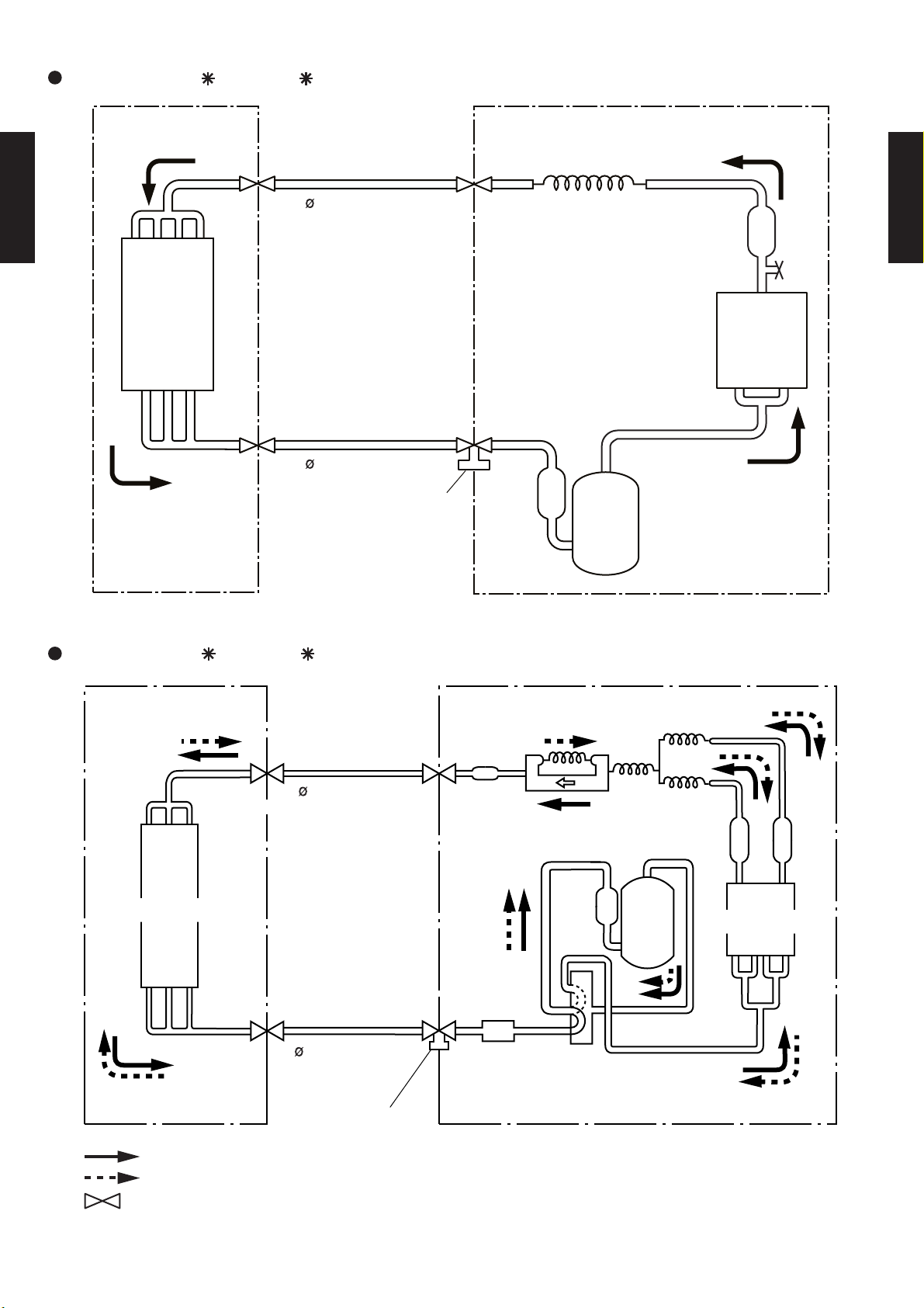
Page 12
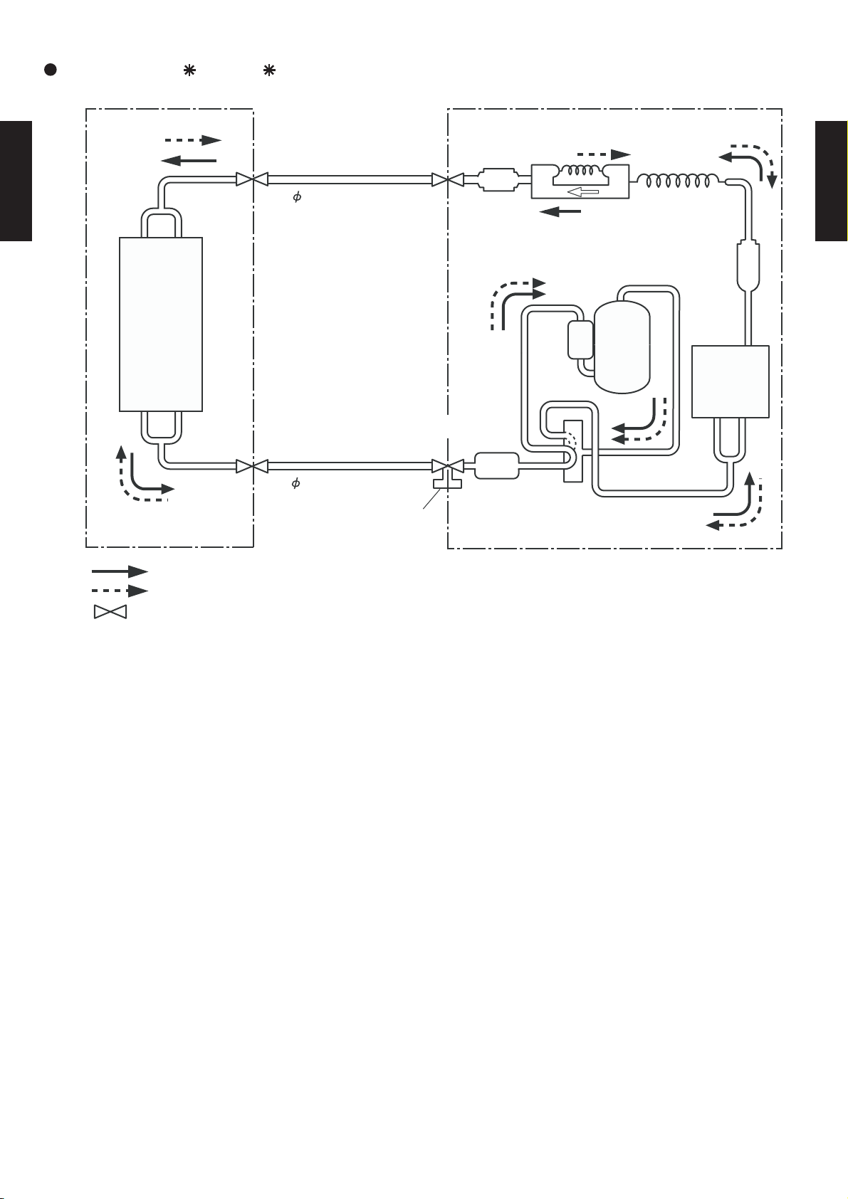
Refrigerant pipe
9.52 mm (3/8")
Refrigerant pipe
6.35 mm (1/4")
Capillary tube
Charging valve
OUTDOOR UNITINDOOR UNIT
Evaporator
Strainer
Strainer
4-Way
valve
Compressor
Muffler
Condenser
Cooling
Heating
: Flare coupling
MODELS : AR
DUCT TYPE
AR7 - AR18K
9U / AO 9U
DUCT TYPE
AR7 - AR18K
- (02 - 11) -
Page 13
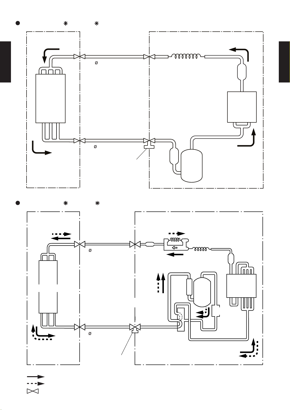
MODELS : AR 12F / AO 12F
Refrigerant pipe
OUTDOOR UNITINDOOR UNIT
6.35mm(1/4")
DUCT TYPE
AR7 - AR18K
Evaporator
Capillary tube
Strainer
Condenser
DUCT TYPE
AR7 - AR18K
Refrigerant pipe
9.52mm(3/8")
Charging valve
Compressor
MODELS : AR 12U / AO 12U
INDOOR UNIT
Distributor
Evaporator
Refrigerant pipe
6.35mm(1/4")
Refrigerant pipe
9.52mm(3/8")
Charging valve
OUTDOOR UNIT
Strainer
Capillary
tube
Compressor
Strainer
Condenser
Muffler
4-Way
valve
Cooling
Heating
: Flare coupling
- (02 - 12) -
Page 14
MODELS : AR 14F / AO 14F
Refrigerant pipe
OUTDOOR UNITINDOOR UNIT
6.35mm(1/4")
Capillary tube
Strainer
DUCT TYPE
AR7 - AR18K
DUCT TYPE
AR7 - AR18K
Evaporator
Condenser
Refrigerant pipe
12.7mm(1/2")
Charging valve
Compressor
MODELS : AR 14U / AO 14U
INDOOR UNIT
Refrigerant pipe
Distributor
Evaporator
6.35mm(1/4")
Refrigerant pipe
12.7mm(1/2")
OUTDOOR UNIT
Strainer
Muffler
4-Way
valve
Capillary
tube
Compressor
Strainer
Condenser
Strainer
Cooling
Heating
: Flare coupling
Charging valve
- (02 - 13) -
Page 15
MODELS : AR 18F / AO 18F
Refrigerant pipe
OUTDOOR UNITINDOOR UNIT
6.35mm(1/4")
Capillary tube
Strainer
DUCT TYPE
AR7 - AR18K
DUCT TYPE
AR7 - AR18K
Evaporator
Condenser
Refrigerant pipe
15.88mm(5/8")
Charging valve
Compressor
MODELS : AR 18U / AO 18U
INDOOR UNIT
Distributor
Evaporator
Refrigerant pipe
6.35mm(1/4")
Accumulator
Refrigerant pipe
15.88mm(5/8")
Charging valve
OUTDOOR UNIT
Capillary
tube
Strainer
Strainer
Compressor
Condenser
Muffler
4-Way
valve
Cooling
Heating
: Flare coupling
- (02 - 14) -
Page 16
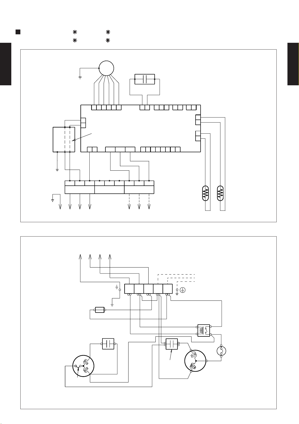
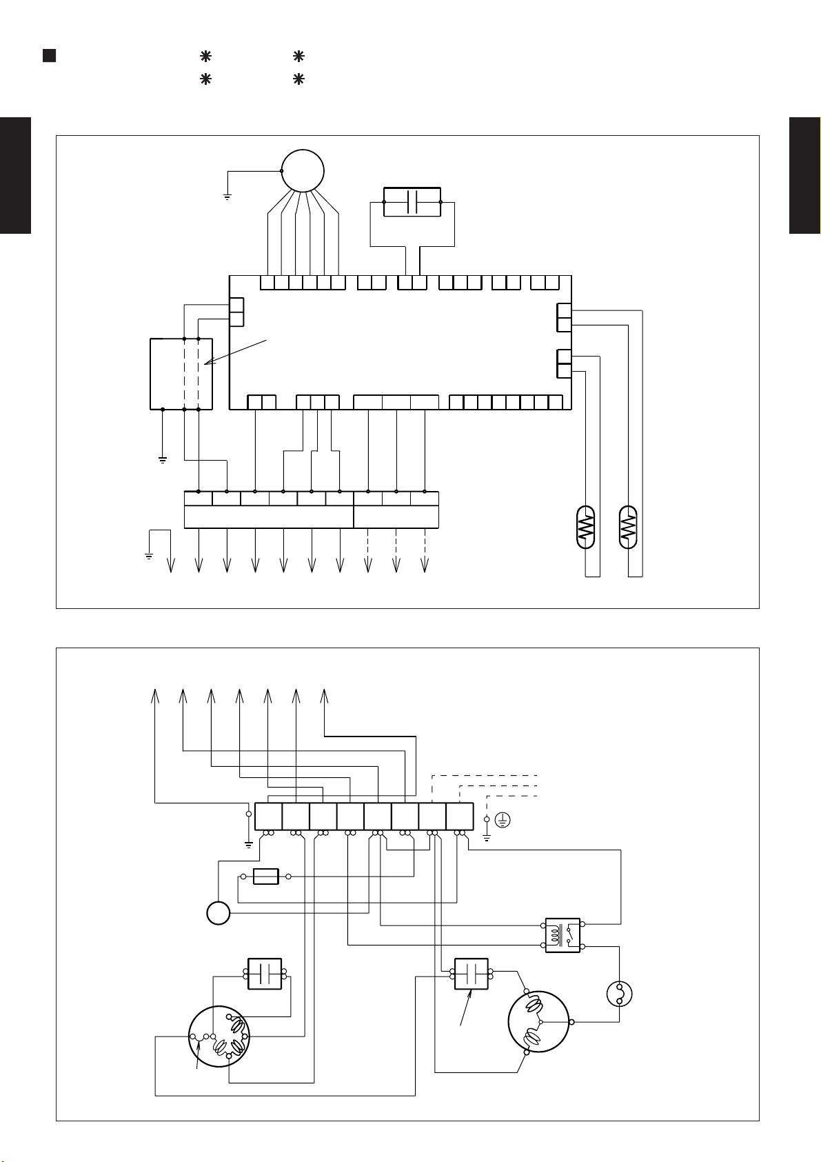
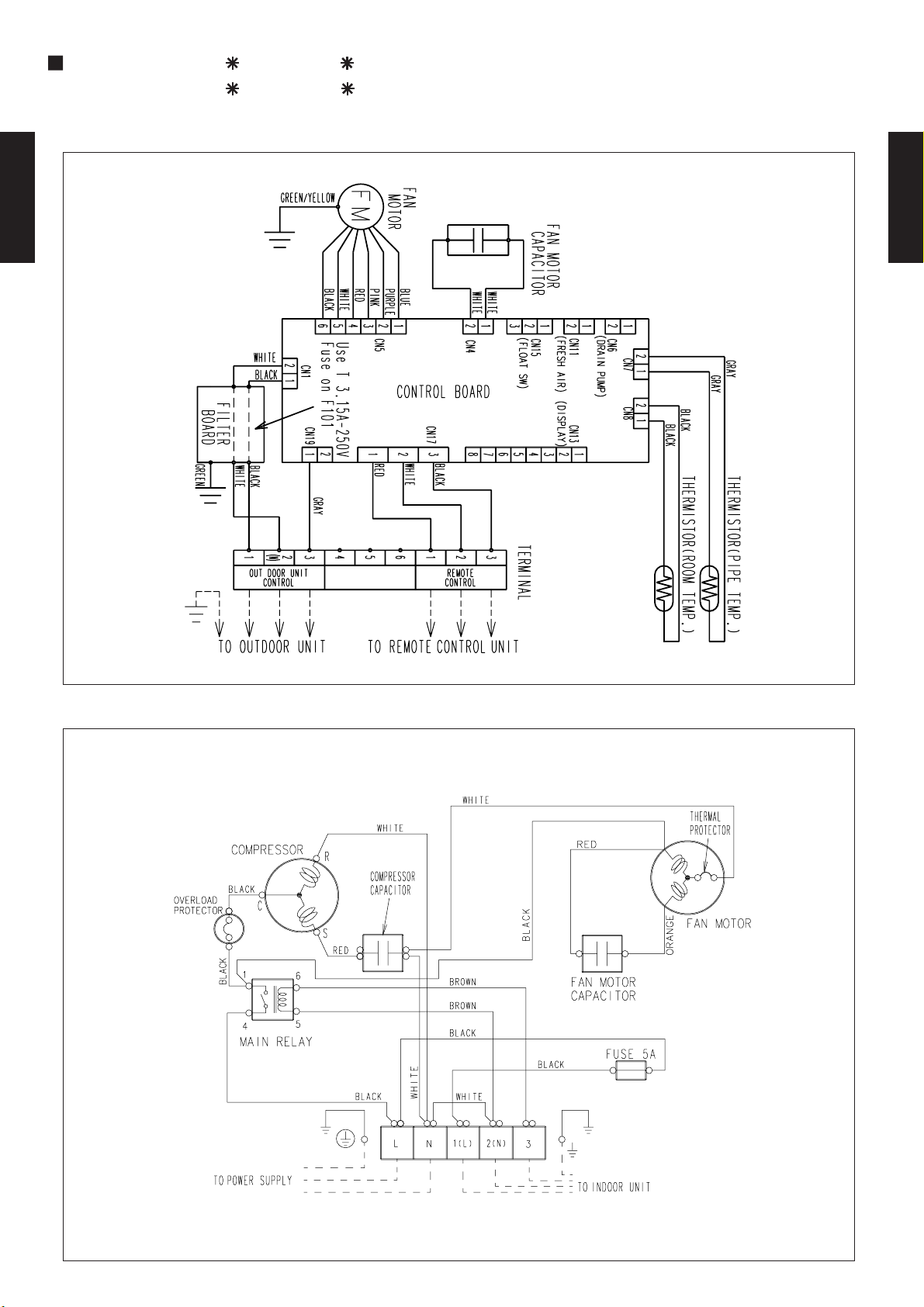
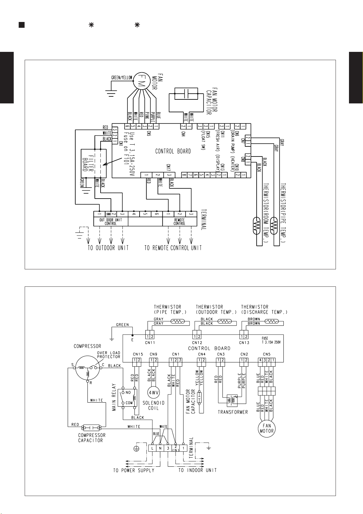
2-6. WIRING DIAGRAMS
MODELS : AR 7F / AO 7F
AR 9F / AO 9F
GREEN / YELLOW
F M
FAN MOTOR
FAN MOTOR
WHITE
678
CAPACITOR
2
11
CN15
( FLOAT SW )
CN13
( DISPLAY )
2
CN11
( FRESH AIR )
2
1
DUCT TYPE
AR7 - AR18K
1
2
CN6
( DRAIN PUMP )
CN7 CN8
2
1
2
BLACK
1
BLACK
GRAY
GRAY
THERMISTOR ( PIPE TEMP. )
THERMISTOR ( ROOM TEMP. )
DUCT TYPE
AR7 - AR18K
WHITE
BLACK
Use T3.15A - 250V
Fuse on F101
WHITE
BLACK
CN1
2
1
CN19
2
1
GREEN
WHITE
BLACK
13456123
OUTDOOR UNIT
CONTROL
GRAY
2 ( N )
PURPLE
BLUE
PINK
RED
1
3
2
44556
CN5
CONTROL BOARD
CN17
1
RED
33
2
WHITE
WHITE
23
1
CN4
BLACK
REMOTE
CONTROL
FAN MOTOR
THERMAL
PROTECTOR
TO INDOOR UNIT
FUSE 5A
FAN MOTOR
CAPACITOR
ORANGE
TOTO OUTDOOR UNIT
REMOTE CONTROL UNIT
2 ( N )
3
WHITE
BLACK
BLACK
RED
WHITE
1 ( L )
BLACK
BROWN
BROWN
LN
BLACK
WHITE
COMPRESSOR
CAPACITOR
WHITE
RED
S
R
TO POWER SOURCE
MAIN RELAY
54
BLACK
1
6
C
BLACK
COMPRESSOR
OVERLOAD
PROTECTOR
- (02 - 15) -
Page 17
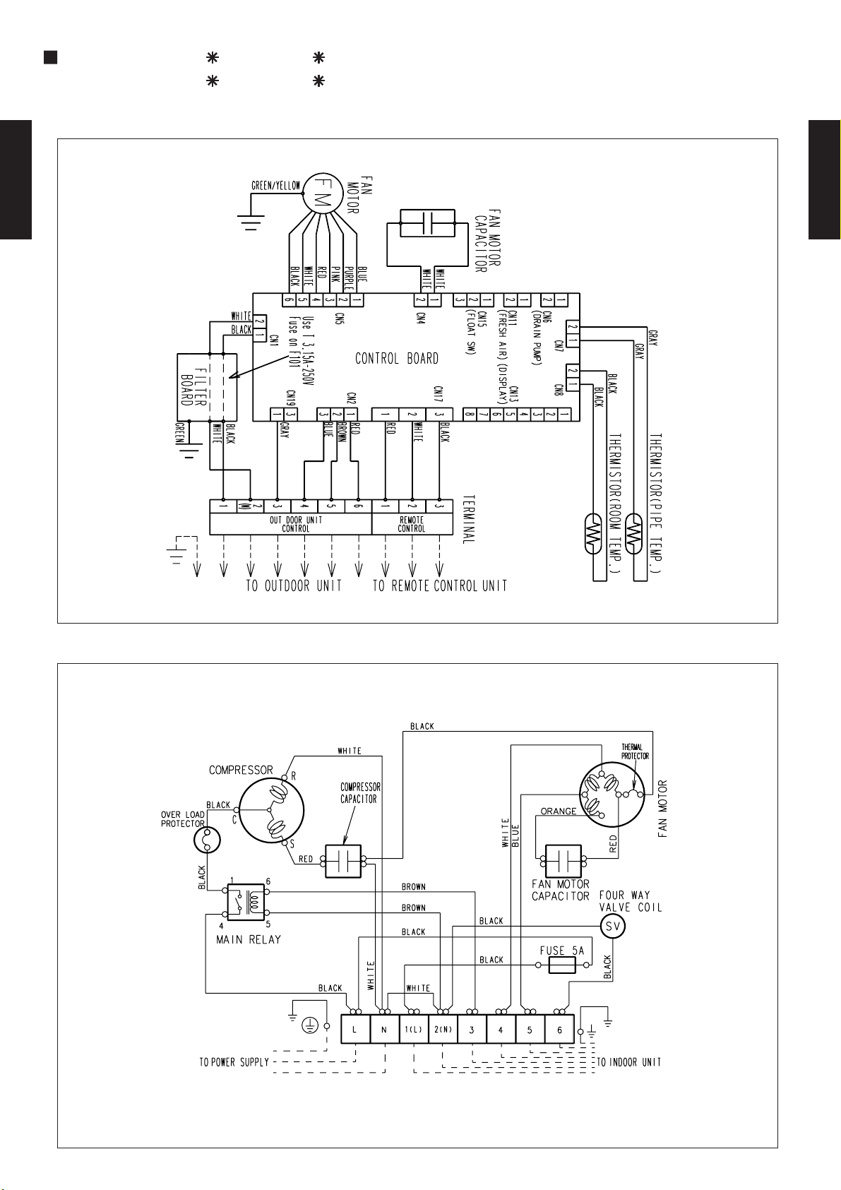
MODELS : AR 7U / AO 7U
AR 9U / AO 9U
GREEN / YELLOW
F M
FAN MOTOR
FAN MOTOR
CAPACITOR
DUCT TYPE
AR7 - AR18K
BLACK
WHITE
56
WHITE
BLACK
FILTER
BOARD
GREEN
WHITE
BLACK
2
1
2 ( N )
OUTDOOR UNIT
CONTROL
CN1
Use T3.15A - 250V
Fuse on F101
CN19
1
GRAY
PURPLE
BLUE
PINK
RED
1
2
3
4
CN5
2
( HEATER )
CONTROL BOARD
CN2
2
1
RED
BROWN
BLUE
56
1
CN10
1
RED
1
REMOTE
CONTROL
WHITE
WHITE
111
3
CN4
( FLOAT SW )
222
CN15
( FRESH AIR )
CN13
( DISPLAY )
CN17
2
3
BLACK
WHITE
2134
3
54678
TERMINAL
1
2
CN6
( DRAIN PUMP )
CN11
2
CN7 CN8
1
2
BLACK
1
BLACK
2
1
333
GRAY
GRAY
THERMISTOR ( ROOM TEMP. )
THERMISTOR ( PIPE TEMP. )
DUCT TYPE
AR7 - AR18K
4-WAY
VALVE COIL
FAN MOTOR
THERMAL
PROTECTOR
TO INDOOR UNIT
6
BLACK
FUSE 5A
SV
FAN MOTOR
CAPACITOR
RED
ORANGE
BLUE
45
BLACK
BLACK
WHITE
TOTO OUTDOOR UNIT
REMOTE CONTROL UNIT
1 ( L )
2 ( N )
WHITE
BLACK
BROWN
BROWN
BLACK
L
N3
WHITE
COMPRESSOR
CAPACITOR
WHITE
BLACK
MAIN RELAY
RED
S
R
TO POWER SOURCE
5
61
4
BLACK
C
BLACK
COMPRESSOR
OVERLOAD
PROTECTOR
- (02 - 16) -
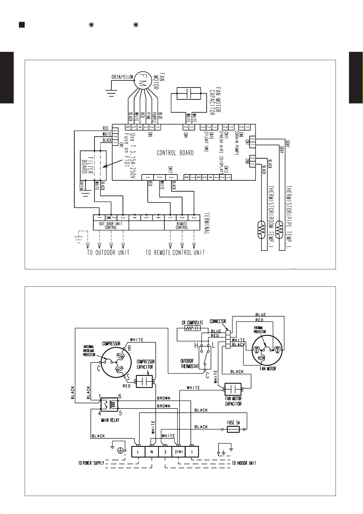
Page 18
MODELS : AR 12F / AO 12F
AR 14F / AO 14F
DUCT TYPE
AR7 - AR18K
DUCT TYPE
AR7 - AR18K
- (02 - 17) -
Page 19
MODELS : AR 12U / AO 12U
AR 14U / AO 14U
DUCT TYPE
AR7 - AR18K
DUCT TYPE
AR7 - AR18K
- (02 - 18) -
Page 20
MODELS : AR 18F / AO 18F
DUCT TYPE
AR7 - AR18K
DUCT TYPE
AR7 - AR18K
- (02 - 19) -
Page 21
MODELS : AR 18U / AO 18U
DUCT TYPE
AR7 - AR18K
DUCT TYPE
AR7 - AR18K
- (02 - 20) -
Page 22
2-7. CAPACITY TABLE
AFR 5.7
(°CDB)
TC SHC PI TC SHC PI TC SHC PI TC SHC PI TC SHC PI TC SHC PI TC SHC PI TC SHC PI
0 2.58 1.83 0.44 2.63 1.73 0.45 2.69 1.82 0.46 2.76 1.90 0.46 2.80 1.88 0.47 2.86 1.85 0.47 2.88 1.83 0.47 2.91 1.91 0.48
5 2.49 1.76 0.50 2.55 1.67 0.51 2.61 1.77 0.51 2.70 1.86 0.52 2.74 1.85 0.52 2.81 1.83 0.53 2.84 1.81 0.53 2.87 1.89 0.54
10 2.38 1.70 0.55 2.44 1.61 0.56 2.50 1.72 0.56 2.61 1.81 0.58 2.65 1.81 0.58 2.72 1.79 0.59 2.75 1.77 0.59 2.78 1.85 0.60
15 2.27 1.64 0.60 2.33 1.55 0.61 2.39 1.66 0.62 2.48 1.76 0.63 2.52 1.75 0.64 2.59 1.74 0.65 2.63 1.73 0.65 2.66 1.81 0.66
20 2.15 1.58 0.66 2.20 1.50 0.67 2.25 1.60 0.67 2.34 1.70 0.69 2.38 1.69 0.69 2.44 1.68 0.71 2.48 1.67 0.71 2.51 1.75 0.72
25 2.24 1.63 0.61 2.29 1.55 0.62 2.35 1.65 0.63 2.43 1.74 0.64 2.47 1.73 0.64 2.54 1.72 0.65 2.57 1.71 0.65 2.60 1.79 0.66
30 2.10 1.56 0.67 2.15 1.48 0.68 2.20 1.59 0.68 2.29 1.68 0.69 2.32 1.67 0.70 2.39 1.66 0.71 2.42 1.65 0.71 2.46 1.73 0.72
35 1.95 1.49 0.73 1.99 1.41 0.74 2.04 1.51 0.74 2.11 1.60 0.75 2.15 1.60 0.76 2.22 1.59 0.77 2.25 1.58 0.77 2.29 1.67 0.78
40 1.77 1.42 0.80 1.80 1.33 0.80 1.84 1.43 0.80 1.92 1.52 0.82 1.95 1.52 0.82 2.02 1.51 0.83 2.05 1.51 0.84 2.09 1.60 0.85
43 1.65 1.35 0.83 1.68 1.28 0.83 1.72 1.37 0.84 1.79 1.47 0.85 1.83 1.47 0.86 1.89 1.46 0.87 1.93 1.46 0.88 1.97 1.56 0.88
21 °CWB
16 °CWB
22 °CWB
Outdoor temperature
12 °CWB
23 °CDB
21 °CDB
15 °CWB
18 °CDB
29 °CDB
Indoor temperature
32 °CDB
23 °CWB
27 °CDB
30 °CDB
18 °CWB
19 °CWB
26 °CDB
AFR 5.7
(°CDB)
TC SHC PI TC SHC PI TC SHC PI TC SHC PI TC SHC PI TC SHC PI TC SHC PI TC SHC PI
21 2.31 1.74 0.57 2.36 1.65 0.57 2.41 1.75 0.58 2.49 1.85 0.59 2.53 1.84 0.59 2.60 1.83 0.60 2.63 1.82 0.61 2.66 1.90 0.61
25 2.24 1.63 0.61 2.29 1.55 0.62 2.35 1.65 0.63 2.43 1.74 0.64 2.47 1.73 0.64 2.54 1.72 0.65 2.57 1.71 0.65 2.60 1.79 0.66
30 2.10 1.56 0.67 2.15 1.48 0.68 2.20 1.59 0.68 2.29 1.68 0.69 2.32 1.67 0.70 2.39 1.66 0.71 2.42 1.65 0.71 2.46 1.73 0.72
35 1.95 1.49 0.73 1.99 1.41 0.74 2.04 1.51 0.74 2.11 1.60 0.75 2.15 1.60 0.76 2.22 1.59 0.77 2.25 1.58 0.77 2.29 1.67 0.78
40 1.77 1.42 0.80 1.80 1.33 0.80 1.84 1.43 0.80 1.92 1.52 0.82 1.95 1.52 0.82 2.02 1.51 0.83 2.05 1.51 0.84 2.09 1.60 0.84
43 1.65 1.35 0.83 1.68 1.28 0.83 1.72 1.37 0.84 1.79 1.47 0.85 1.83 1.47 0.86 1.89 1.46 0.87 1.93 1.46 0.88 1.97 1.56 0.88
29 °CDB
Indoor temperature
32 °CDB
23 °CWB
27 °CDB
30 °CDB
18 °CWB
19 °CWB
26 °CDB
23 °CDB
21 °CDB
15 °CWB
18 °CDB
21 °CWB
16 °CWB
22 °CWB
Outdoor temperature
12 °CWB
AFR 7.0
(°CDB)
TC SHC PI TC SHC PI TC SHC PI TC SHC PI TC SHC PI TC SHC PI TC SHC PI TC SHC PI
0 3.25 2.30 0.56 3.31 2.17 0.57 3.37 2.29 0.58 3.47 2.39 0.59 3.51 2.37 0.59 3.59 2.33 0.60 3.62 2.31 0.60 3.65 2.40 0.60
5 3.13 2.21 0.63 3.20 2.10 0.64 3.28 2.23 0.65 3.39 2.34 0.66 3.44 2.33 0.66 3.53 2.30 0.67 3.56 2.28 0.67 3.60 2.38 0.68
10 3.00 2.14 0.69 3.07 2.03 0.71 3.14 2.16 0.71 3.27 2.28 0.73 3.32 2.27 0.73 3.41 2.25 0.74 3.45 2.23 0.75 3.49 2.33 0.76
15 2.85 2.06 0.76 2.92 1.95 0.77 3.00 2.09 0.78 3.12 2.21 0.80 3.17 2.20 0.81 3.26 2.18 0.82 3.30 2.17 0.82 3.34 2.27 0.83
20 2.70 1.99 0.83 2.76 1.88 0.84 2.83 2.01 0.85 2.94 2.13 0.87 2.98 2.13 0.88 3.07 2.11 0.89 3.11 2.10 0.90 3.15 2.20 0.91
25 2.81 2.05 0.78 2.88 1.94 0.78 2.95 2.07 0.79 3.05 2.19 0.80 3.10 2.18 0.81 3.19 2.16 0.82 3.22 2.15 0.82 3.26 2.25 0.83
30 2.63 1.96 0.85 2.71 1.87 0.86 2.77 1.99 0.86 2.87 2.11 0.88 2.92 2.10 0.88 3.00 2.08 0.90 3.04 2.07 0.90 3.08 2.18 0.91
35 2.45 1.88 0.93 2.49 1.77 0.93 2.56 1.90 0.94 2.65 2.02 0.95 2.70 2.01 0.96 2.79 2.00 0.97 2.83 1.99 0.98 2.87 2.10 0.98
40 2.23 1.78 1.01 2.26 1.67 1.01 2.31 1.80 1.02 2.41 1.91 1.03 2.45 1.91 1.04 2.54 1.90 1.05 2.58 1.90 1.06 2.62 2.01 1.07
43 2.07 1.70 1.05 2.11 1.60 1.05 2.15 1.73 1.06 2.25 1.85 1.08 2.29 1.85 1.08 2.38 1.84 1.10 2.43 1.84 1.11 2.47 1.96 1.11
29 °CDB
Indoor temperature
32 °CDB
23 °CWB
27 °CDB
30 °CDB
18 °CWB
19 °CWB
26 °CDB
23 °CDB
21 °CDB
15 °CWB
18 °CDB
21 °CWB
16 °CWB
22 °CWB
Outdoor temperature
12 °CWB
AFR 7.0
(°CDB)
TC SHC PI TC SHC PI TC SHC PI TC SHC PI TC SHC PI TC SHC PI TC SHC PI TC SHC PI
21 3.01 2.29 0.74 3.07 2.18 0.75 3.14 2.31 0.75 3.25 2.44 0.76 3.30 2.43 0.77 3.39 2.41 0.78 3.43 2.40 0.79 3.47 2.51 0.80
25 2.91 2.16 0.80 2.99 2.04 0.81 3.05 2.18 0.82 3.17 2.30 0.83 3.22 2.29 0.83 3.30 2.27 0.84 3.34 2.25 0.85 3.38 2.36 0.85
30 2.73 2.06 0.88 2.81 1.96 0.88 2.87 2.09 0.89 2.98 2.21 0.90 3.03 2.21 0.91 3.11 2.19 0.92 3.16 2.18 0.93 3.20 2.29 0.93
35 2.54 1.97 0.96 2.59 1.86 0.96 2.65 2.00 0.97 2.75 2.12 0.98 2.80 2.11 0.99 2.89 2.10 1.00 2.93 2.09 1.01 2.98 2.21 1.02
40 2.31 1.87 1.04 2.34 1.76 1.04 2.40 1.89 1.05 2.50 2.01 1.06 2.54 2.01 1.07 2.63 2.00 1.09 2.68 1.99 1.09 2.72 2.11 1.10
43 2.15 1.79 1.08 2.18 1.68 1.09 2.23 1.81 1.09 2.33 1.94 1.11 2.38 1.94 1.12 2.47 1.93 1.14 2.52 1.93 1.14 2.56 2.05 1.15
21 °CWB
16 °CWB
22 °CWB
Outdoor temperature
12 °CWB
23 °CDB
21 °CDB
15 °CWB
18 °CDB
29 °CDB
Indoor temperature
32 °CDB
23 °CWB
27 °CDB
30 °CDB
18 °CWB
19 °CWB
26 °CDB
2-7-1. COOLING
MODELS : AR 7U / AO 7U
DUCT TYPE
AR7 - AR18K
MODELS : AR 7F / AO 7F
COOLING CAPACITY
DUCT TYPE
AR7 - AR18K
MODELS : AR 9U / AO 9U
MODELS : AR 9F / AO 9F
AFR: Air flow rate (m3/min)
TC : Total capacity (kW)
SHC: Sensible Heat capacity (kW)
PI : Power Input (kW)
- (02 - 21) -
Page 23
MODELS : AR 12U / AO 12U
AFR 8.3
(°CDB)
TC SHC PI TC SHC PI TC SHC PI TC SHC PI TC SHC PI TC SHC PI TC SHC PI TC SHC PI
0 4.21 3.05 0.72 4.29 2.89 0.74 4.37 3.05 0.75 4.50 3.17 0.76 4.55 3.15 0.76 4.65 3.09 0.77 4.69 3.07 0.77 4.73 3.19 0.78
5 4.06 2.94 0.81 4.15 2.79 0.82 4.25 2.97 0.83 4.40 3.12 0.85 4.46 3.10 0.85 4.57 3.05 0.87 4.62 3.03 0.87 4.67 3.16 0.88
10 3.88 2.84 0.89 3.98 2.69 0.91 4.08 2.87 0.92 4.24 3.03 0.94 4.31 3.02 0.95 4.42 2.99 0.96 4.47 2.97 0.97 4.52 3.10 0.98
15 3.70 2.74 0.98 3.79 2.59 1.00 3.89 2.77 1.01 4.04 2.94 1.03 4.11 2.93 1.04 4.22 2.90 1.06 4.28 2.88 1.07 4.33 3.02 1.07
20 3.50 2.65 1.07 3.58 2.50 1.09 3.67 2.68 1.10 3.81 2.84 1.12 3.87 2.83 1.13 3.98 2.80 1.15 4.03 2.79 1.16 4.08 2.93 1.17
25 3.64 2.73 1.00 3.73 2.59 1.01 3.82 2.76 1.02 3.96 2.91 1.04 4.02 2.90 1.04 4.13 2.87 1.06 4.18 2.85 1.06 4.23 2.99 1.07
30 3.41 2.60 1.10 3.51 2.48 1.11 3.59 2.65 1.12 3.72 2.80 1.13 3.78 2.80 1.14 3.89 2.77 1.16 3.95 2.76 1.16 4.00 2.90 1.17
35 3.17 2.49 1.20 3.23 2.35 1.20 3.32 2.53 1.21 3.44 2.68 1.23 3.50 2.67 1.24 3.61 2.66 1.26 3.67 2.65 1.26 3.72 2.79 1.27
40 2.89 2.37 1.30 2.93 2.22 1.30 3.00 2.39 1.31 3.12 2.54 1.33 3.18 2.54 1.34 3.29 2.53 1.36 3.34 2.52 1.37 3.40 2.67 1.39
43 2.68 2.26 1.36 2.73 2.13 1.36 2.79 2.30 1.37 2.91 2.46 1.39 2.97 2.46 1.40 3.08 2.45 1.42 3.14 2.45 1.43 3.20 2.60 1.44
21 °CWB
16 °CWB
22 °CWB
Outdoor temperature
12 °CWB
23 °CDB
21 °CDB
15 °CWB
18 °CDB
29 °CDB
Indoor temperature
32 °CDB
23 °CWB
27 °CDB
30 °CDB
18 °CWB
19 °CWB
26 °CDB
AFR 8.3
(°CDB)
TC SHC PI TC SHC PI TC SHC PI TC SHC PI TC SHC PI TC SHC PI TC SHC PI TC SHC PI
21 3.76 2.90 0.93 3.84 2.76 0.94 3.92 2.93 0.95 4.06 3.09 0.96 4.12 3.08 0.97 4.23 3.06 0.98 4.29 3.04 0.99 4.34 3.18 1.00
25 3.64 2.73 1.00 3.73 2.59 1.01 3.82 2.76 1.02 3.96 2.91 1.04 4.02 2.90 1.04 4.13 2.87 1.06 4.18 2.85 1.06 4.23 2.99 1.07
30 3.41 2.60 1.10 3.51 2.48 1.11 3.59 2.65 1.12 3.72 2.80 1.13 3.78 2.80 1.14 3.89 2.77 1.16 3.95 2.76 1.16 4.00 2.90 1.17
35 3.17 2.49 1.20 3.23 2.35 1.20 3.32 2.53 1.21 3.44 2.68 1.23 3.50 2.67 1.24 3.61 2.66 1.26 3.67 2.65 1.26 3.72 2.79 1.27
40 2.89 2.37 1.30 2.93 2.22 1.30 3.00 2.39 1.31 3.12 2.54 1.33 3.18 2.54 1.34 3.29 2.53 1.36 3.34 2.52 1.37 3.40 2.67 1.38
43 2.68 2.26 1.35 2.73 2.13 1.36 2.79 2.30 1.37 2.91 2.46 1.39 2.97 2.46 1.40 3.08 2.45 1.42 3.14 2.45 1.43 3.20 2.60 1.44
29 °CDB
Indoor temperature
32 °CDB
23 °CWB
27 °CDB
30 °CDB
18 °CWB
19 °CWB
26 °CDB
23 °CDB
21 °CDB
15 °CWB
18 °CDB
21 °CWB
16 °CWB
22 °CWB
Outdoor temperature
12 °CWB
AFR 10.7
(°CDB)
TC SHC PI TC SHC PI TC SHC PI TC SHC PI TC SHC PI TC SHC PI TC SHC PI TC SHC PI
0 4.81 3.39 0.82 4.90 3.20 0.85 5.00 3.38 0.85 5.14 3.52 0.87 5.20 3.50 0.87 5.31 3.43 0.88 5.36 3.40 0.89 5.41 3.54 0.89
5 4.64 3.26 0.93 4.74 3.09 0.94 4.86 3.29 0.95 5.03 3.46 0.97 5.10 3.44 0.98 5.22 3.39 0.99 5.28 3.36 1.00 5.33 3.51 1.00
10 4.44 3.15 1.02 4.55 2.99 1.04 4.66 3.19 1.06 4.85 3.37 1.08 4.92 3.35 1.08 5.05 3.32 1.10 5.11 3.29 1.11 5.17 3.44 1.12
15 4.23 3.04 1.12 4.33 2.87 1.14 4.44 3.08 1.16 4.62 3.26 1.18 4.69 3.25 1.19 4.82 3.22 1.21 4.89 3.20 1.22 4.94 3.35 1.23
20 4.00 2.94 1.23 4.09 2.78 1.25 4.19 2.97 1.26 4.35 3.15 1.29 4.42 3.14 1.30 4.55 3.11 1.32 4.61 3.09 1.33 4.67 3.25 1.34
25 4.16 3.03 1.15 4.27 2.87 1.16 4.36 3.06 1.17 4.53 3.23 1.19 4.60 3.22 1.20 4.72 3.18 1.21 4.78 3.17 1.22 4.83 3.32 1.22
30 3.90 2.89 1.26 4.01 2.75 1.27 4.10 2.94 1.28 4.25 3.11 1.30 4.32 3.10 1.31 4.45 3.08 1.32 4.51 3.06 1.33 4.57 3.22 1.34
35 3.63 2.77 1.37 3.69 2.61 1.38 3.79 2.81 1.39 3.93 2.98 1.41 4.00 2.97 1.42 4.13 2.95 1.44 4.19 2.94 1.45 4.25 3.10 1.46
40 3.30 2.63 1.49 3.35 2.47 1.49 3.43 2.65 1.50 3.57 2.82 1.52 3.64 2.82 1.54 3.76 2.81 1.56 3.82 2.80 1.57 3.88 2.97 1.59
43 3.07 2.51 1.56 3.12 2.37 1.56 3.19 2.55 1.57 3.33 2.73 1.59 3.40 2.73 1.60 3.52 2.72 1.63 3.59 2.72 1.64 3.66 2.89 1.65
29 °CDB
Indoor temperature
32 °CDB
23 °CWB
27 °CDB
30 °CDB
18 °CWB
19 °CWB
26 °CDB
23 °CDB
21 °CDB
15 °CWB
18 °CDB
21 °CWB
16 °CWB
22 °CWB
Outdoor temperature
12 °CWB
AFR 10.7
(°CDB)
TC SHC PI TC SHC PI TC SHC PI TC SHC PI TC SHC PI TC SHC PI TC SHC PI TC SHC PI
21 4.51 3.44 1.04 4.60 3.26 1.05 4.70 3.47 1.06 4.87 3.66 1.07 4.95 3.65 1.08 5.08 3.62 1.10 5.14 3.60 1.11 5.20 3.77 1.12
25 4.37 3.23 1.12 4.48 3.06 1.14 4.58 3.27 1.15 4.75 3.45 1.16 4.83 3.44 1.17 4.96 3.40 1.19 5.02 3.38 1.19 5.07 3.54 1.20
30 4.09 3.09 1.23 4.21 2.94 1.24 4.31 3.14 1.25 4.47 3.32 1.27 4.54 3.31 1.28 4.67 3.28 1.30 4.74 3.27 1.30 4.80 3.44 1.31
35 3.81 2.96 1.34 3.88 2.78 1.35 3.98 3.00 1.36 4.13 3.18 1.38 4.20 3.17 1.39 4.33 3.15 1.41 4.40 3.14 1.42 4.46 3.31 1.43
40 3.46 2.80 1.45 3.52 2.63 1.46 3.60 2.83 1.47 3.75 3.01 1.49 3.82 3.01 1.50 3.95 3.00 1.53 4.01 2.99 1.54 4.08 3.17 1.55
43 3.22 2.68 1.52 3.28 2.53 1.53 3.35 2.72 1.54 3.50 2.91 1.56 3.57 2.91 1.57 3.70 2.90 1.59 3.77 2.90 1.60 3.84 3.08 1.61
21 °CWB
16 °CWB
22 °CWB
Outdoor temperature
12 °CWB
23 °CDB
21 °CDB
15 °CWB
18 °CDB
29 °CDB
Indoor temperature
32 °CDB
23 °CWB
27 °CDB
30 °CDB
18 °CWB
19 °CWB
26 °CDB
DUCT TYPE
AR7 - AR18K
COOLING CAPACITY
DUCT TYPE
AR7 - AR18K
MODELS : AR 12F / AO 12F
MODELS : AR 14U / AO 14U
MODELS : AR 14F / AO 14F
AFR: Air flow rate (m3/min)
TC : Total capacity (kW)
SHC: Sensible Heat capacity (kW)
PI : Power Input (kW)
- (02 - 22) -
Page 24
MODELS : AR 18U / AO 18U
AFR 16.7
(°CDB)
TC SHC PI TC SHC PI TC SHC PI TC SHC PI TC SHC PI TC SHC PI TC SHC PI TC SHC PI
21 5.80 4.67 1.52 5.92 4.43 1.53 6.05 4.71 1.55 6.27 4.97 1.57 6.36 4.95 1.58 6.53 4.91 1.61 6.61 4.89 1.62 6.69 5.12 1.64
25 5.62 4.39 1.64 5.76 4.16 1.66 5.89 4.43 1.67 6.11 4.68 1.70 6.20 4.66 1.71 6.37 4.61 1.73 6.45 4.58 1.74 6.52 4.81 1.75
30 5.26 4.19 1.80 5.41 3.99 1.81 5.54 4.26 1.83 5.74 4.51 1.86 5.84 4.49 1.87 6.01 4.45 1.89 6.09 4.43 1.91 6.17 4.66 1.92
35 4.90 4.01 1.96 4.99 3.78 1.97 5.12 4.07 1.99 5.31 4.31 2.02 5.40 4.30 2.03 5.57 4.27 2.06 5.66 4.26 2.07 5.74 4.49 2.08
40 4.45 3.81 2.12 4.52 3.57 2.13 4.63 3.84 2.15 4.82 4.09 2.18 4.91 4.09 2.19 5.07 4.07 2.23 5.16 4.06 2.24 5.24 4.30 2.26
43 4.14 3.63 2.22 4.21 3.43 2.23 4.31 3.69 2.24 4.50 3.95 2.28 4.59 3.95 2.29 4.76 3.94 2.33 4.85 3.94 2.34 4.94 4.18 2.36
29 °CDB
Indoor temperature
32 °CDB
23 °CWB
27 °CDB
30 °CDB
18 °CWB
19 °CWB
26 °CDB
23 °CDB
21 °CDB
15 °CWB
18 °CDB
21 °CWB
16 °CWB
22 °CWB
Outdoor temperature
12 °CWB
AFR 16.7
(°CDB)
TC SHC PI TC SHC PI TC SHC PI TC SHC PI TC SHC PI TC SHC PI TC SHC PI TC SHC PI
0 6.49 4.91 1.11 6.62 4.64 1.14 6.74 4.90 1.15 6.94 5.10 1.17 7.02 5.06 1.18 7.17 4.98 1.19 7.24 4.93 1.20 7.30 5.13 1.20
5 6.26 4.73 1.25 6.40 4.48 1.28 6.56 4.77 1.29 6.79 5.01 1.31 6.88 4.98 1.32 7.05 4.91 1.34 7.13 4.87 1.35 7.20 5.08 1.36
10 5.99 4.56 1.38 6.14 4.33 1.41 6.29 4.61 1.43 6.54 4.88 1.45 6.65 4.86 1.47 6.82 4.80 1.49 6.90 4.77 1.50 6.98 4.99 1.51
15 5.71 4.41 1.51 5.85 4.16 1.55 6.00 4.46 1.56 6.24 4.73 1.60 6.33 4.71 1.61 6.51 4.66 1.64 6.60 4.64 1.65 6.67 4.86 1.66
20 5.41 4.26 1.66 5.52 4.02 1.69 5.66 4.30 1.70 5.87 4.56 1.74 5.97 4.54 1.75 6.14 4.50 1.78 6.22 4.48 1.80 6.30 4.71 1.81
25 5.62 4.39 1.55 5.76 4.16 1.57 5.89 4.43 1.58 6.11 4.68 1.61 6.20 4.66 1.62 6.37 4.61 1.64 6.45 4.58 1.65 6.52 4.81 1.66
30 5.26 4.19 1.70 5.41 3.99 1.72 5.54 4.26 1.73 5.74 4.51 1.75 5.84 4.49 1.77 6.01 4.45 1.79 6.09 4.43 1.80 6.17 4.66 1.81
35 4.90 4.01 1.85 4.99 3.78 1.86 5.12 4.07 1.88 5.31 4.31 1.91 5.40 4.30 1.92 5.57 4.27 1.95 5.66 4.26 1.96 5.74 4.49 1.97
40 4.45 3.81 2.01 4.52 3.57 2.02 4.63 3.84 2.03 4.82 4.09 2.06 4.91 4.09 2.08 5.07 4.07 2.11 5.16 4.06 2.12 5.24 4.30 2.15
43 4.14 3.63 2.10 4.21 3.43 2.11 4.31 3.69 2.12 4.50 3.95 2.15 4.59 3.95 2.17 4.76 3.94 2.20 4.85 3.94 2.21 4.94 4.18 2.23
21 °CWB
16 °CWB
22 °CWB
Outdoor temperature
12 °CWB
23 °CDB
21 °CDB
15 °CWB
18 °CDB
29 °CDB
Indoor temperature
32 °CDB
23 °CWB
27 °CDB
30 °CDB
18 °CWB
19 °CWB
26 °CDB
DUCT TYPE
AR7 - AR18K
COOLING CAPACITY
DUCT TYPE
AR7 - AR18K
MODELS : AR 18F / AO 18F
AFR: Air flow rate (m3/min)
TC : Total capacity (kW)
SHC: Sensible Heat capacity (kW)
PI : Power Input (kW)
- (02 - 23) -
Page 25
2-7-2. HEATING
(°CDB) (°CWB) TC PI TC PI TC PI TC PI TC PI TC PI TC PI
-6 -8 1.59 0.48 1.57 0.49 1.52 0.51 1.47 0.52 1.45 0.53 1.40 0.55 1.35 0.55
-4 -6 1.74 0.52 1.72 0.53 1.67 0.55 1.62 0.56 1.59 0.57 1.54 0.59 1.49 0.59
1 -1 1.96 0.59 1.94 0.60 1.89 0.62 1.84 0.63 1.81 0.64 1.76 0.65 1.72 0.66
5 3 2.40 0.71 2.38 0.72 2.33 0.74 2.28 0.75 2.25 0.76 2.21 0.78 2.16 0.78
7 6 2.52 0.73 2.50 0.74 2.45 0.76 2.40 0.78 2.38 0.78 2.33 0.80 2.28 0.81
12 10 2.70 0.78 2.67 0.80 2.62 0.81 2.57 0.83 2.55 0.84 2.50 0.85 2.45 0.86
15 13 2.72 0.81 2.70 0.83 2.65 0.84 2.60 0.86 2.57 0.87 2.52 0.88 2.47 0.89
20 15 2.52 0.73 2.50 0.74 2.45 0.76 2.40 0.78 2.38 0.78 2.33 0.80 2.28 0.81
24 17 2.38 0.68 2.35 0.70 2.30 0.71 2.25 0.73 2.23 0.74 2.18 0.75 2.13 0.76
Indoor temperature
Outdoor temperature
27 °CDB
30 °CDB
25 °CDB
23 °CDB
16 °CDB
18 °CDB
20 °CDB
(°CDB)
(°CWB) TC PI TC PI TC PI TC PI TC PI TC PI TC PI
-6 -8 2.02 0.60 1.98 0.62 1.92 0.64 1.86 0.66 1.83 0.67 1.77 0.69 1.71 0.70
-4 -6 2.20 0.65 2.17 0.67 2.11 0.69 2.05 0.71 2.02 0.72 1.95 0.74 1.89 0.75
1 -1 2.48 0.74 2.45 0.76 2.39 0.78 2.33 0.80 2.29 0.81 2.23 0.83 2.17 0.84
5 3 3.04 0.89 3.01 0.91 2.95 0.93 2.88 0.95 2.85 0.96 2.79 0.98 2.73 0.99
7 6 3.19 0.92 3.16 0.94 3.10 0.96 3.04 0.98 3.01 0.99 2.95 1.01 2.88 1.02
12 10 3.41 0.99 3.38 1.01 3.32 1.03 3.26 1.05 3.22 1.06 3.16 1.08 3.10 1.08
15 13 3.44 1.03 3.41 1.05 3.35 1.07 3.29 1.08 3.26 1.09 3.19 1.11 3.13 1.12
20 15 3.19 0.92 3.16 0.94 3.10 0.96 3.04 0.98 3.01 0.99 2.95 1.01 2.88 1.02
24 17 3.01 0.86 2.98 0.88 2.91 0.90 2.85 0.92 2.82 0.93 2.76 0.95 2.70 0.96
Indoor temperature
Outdoor temperature
27 °CDB
30 °CDB
25 °CDB
23 °CDB
16 °CDB
18 °CDB
20 °CDB
(°CDB)
(°CWB) TC PI TC PI TC PI TC PI TC PI TC PI TC PI
-6 -8 2.60 0.76 2.56 0.79 2.48 0.81 2.40 0.83 2.36 0.85 2.28 0.87 2.20 0.88
-4 -6 2.84 0.82 2.80 0.85 2.72 0.87 2.64 0.90 2.60 0.91 2.52 0.93 2.44 0.94
1 -1 3.20 0.93 3.16 0.96 3.08 0.98 3.00 1.00 2.96 1.02 2.88 1.04 2.80 1.05
5 3 3.92 1.13 3.88 1.15 3.80 1.17 3.72 1.20 3.68 1.21 3.60 1.23 3.52 1.25
7 6 4.12 1.16 4.08 1.19 4.00 1.21 3.92 1.23 3.88 1.25 3.80 1.27 3.72 1.28
12 10 4.40 1.25 4.36 1.27 4.28 1.29 4.20 1.32 4.16 1.33 4.08 1.36 4.00 1.37
15 13 4.44 1.29 4.40 1.32 4.32 1.34 4.24 1.37 4.20 1.38 4.12 1.40 4.04 1.42
20 15 4.12 1.16 4.08 1.19 4.00 1.21 3.92 1.23 3.88 1.25 3.80 1.27 3.72 1.28
24 17 3.88 1.09 3.84 1.11 3.76 1.14 3.68 1.16 3.64 1.17 3.56 1.20 3.48 1.21
Indoor temperature
Outdoor temperature
27 °CDB
30 °CDB
25 °CDB
23 °CDB
16 °CDB
18 °CDB
20 °CDB
MODELS : AR 7U / AO 7U
AFR 5.7
DUCT TYPE
AR7 - AR18K
MODELS : AR 9U / AO 9U
AFR 7.0
HEATING CAPACITY
DUCT TYPE
AR7 - AR18K
MODELS : AR 12U / AO 12U
AFR 8.3
- (02 - 24) -
Page 26

MODELS : AR 14U / AO 14U
(°CDB)
(°CWB) TC PI TC PI TC PI TC PI TC PI TC PI T C PI
-6 -8 3.06 0.85 3.01 0.88 2.91 0.90 2.82 0.93 2.77 0.95 2.68 0.97 2.59 0.99
-4 -6 3.34 0.92 3.29 0.95 3.20 0.97 3.10 1.00 3.06 1.01 2.96 1.04 2.87 1.05
1 -1 3.76 1.04 3.71 1.07 3.62 1.09 3.53 1.12 3.48 1.13 3.38 1.16 3.29 1.17
5 3 4.61 1.26 4.56 1.28 4.47 1.31 4.37 1.34 4.32 1.35 4.23 1.38 4.14 1.39
7 6 4.84 1.30 4.79 1.32 4.70 1.35 4.61 1.38 4.56 1.39 4.47 1.42 4.37 1.43
12 10 5.17 1.39 5.12 1.42 5.03 1.44 4.94 1.47 4.89 1.49 4.79 1.51 4.70 1.53
15 13 5.22 1.44 5.17 1.47 5.08 1.50 4.98 1.53 4.94 1.54 4.84 1.57 4.75 1.58
20 15 4.84 1.30 4.79 1.32 4.70 1.35 4.61 1.38 4.56 1.39 4.47 1.42 4.37 1.43
24 17 4.56 1.22 4.51 1.24 4.42 1.27 4.32 1.30 4.28 1.31 4.18 1.34 4.09 1.35
Indoor temperature
Outdoor temperature
27 °CDB
30 °CDB
25 °CDB
23 °CDB
16 °CDB
18 °CDB
20 °CDB
(°CDB)
(°CWB) TC PI TC PI TC PI TC PI TC PI TC PI T C PI
-6 -8 3.90 1.18 3.84 1.22 3.72 1.25 3.60 1.29 3.54 1.31 3.42 1.35 3.30 1.37
-4 -6 4.26 1.27 4.20 1.31 4.08 1.35 3.96 1.38 3.90 1.40 3.78 1.44 3.66 1.46
1 -1 4.80 1.44 4.74 1.48 4.62 1.51 4.50 1.55 4.44 1.57 4.32 1.61 4.20 1.63
5 3 5.88 1.74 5.82 1.78 5.70 1.81 5.58 1.85 5.52 1.87 5.40 1.91 5.28 1.93
7 6 6.18 1.80 6.12 1.83 6.00 1.87 5.88 1.91 5.82 1.93 5.70 1.96 5.58 1.98
12 10 6.60 1.93 6.54 1.96 6.42 2.00 6.30 2.04 6.24 2.06 6.12 2.09 6.00 2.11
15 13 6.66 2.00 6.60 2.04 6.48 2.08 6.36 2.11 6.30 2.13 6.18 2.17 6.06 2.19
20 15 6.18 1.80 6.12 1.83 6.00 1.87 5.88 1.91 5.82 1.93 5.70 1.96 5.58 1.98
24 17 5.82 1.68 5.76 1.72 5.64 1.76 5.52 1.80 5.46 1.81 5.34 1.85 5.22 1.87
Indoor temperature
Outdoor temperature
27 °CDB
30 °CDB
25 °CDB
23 °CDB
16 °CDB
18 °CDB
20 °CDB
AFR 10.7
DUCT TYPE
AR7 - AR18K
HEATING CAPACITY
DUCT TYPE
AR7 - AR18K
MODELS : AR 18U / AO 18U
AFR 16.7
AFR: Air flow rate (m3/min)
TC : Total capacity (kW)
SHC: Sensible Heat capacity (kW)
PI : Power Input (kW)
- (02 - 25) -
Page 27
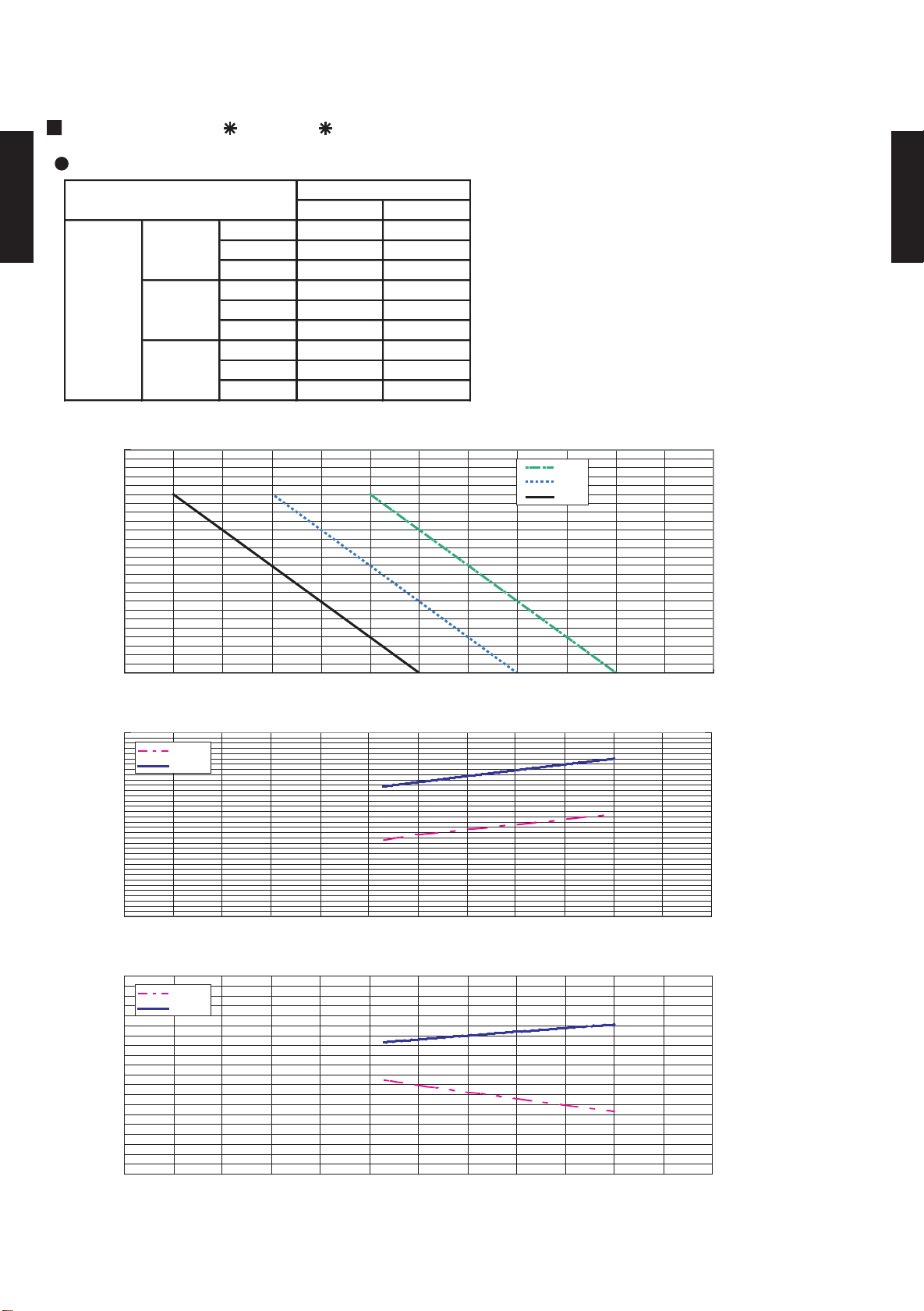
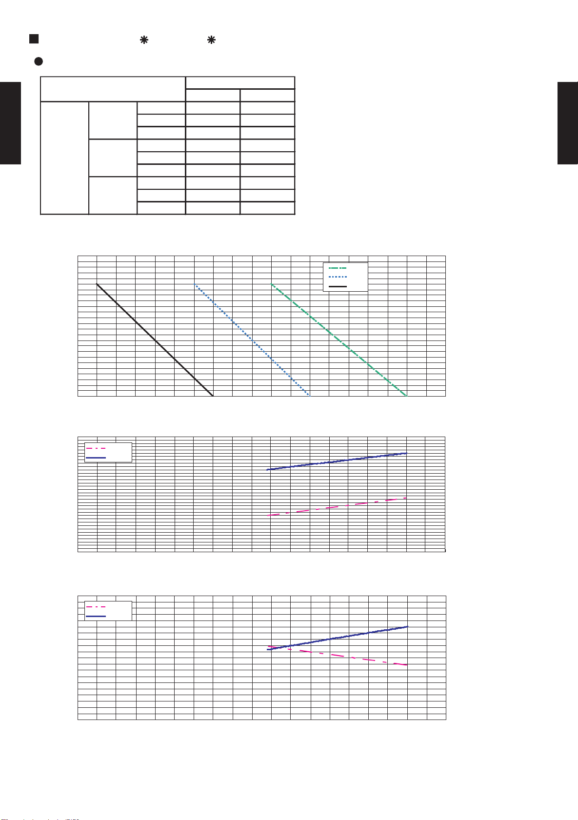
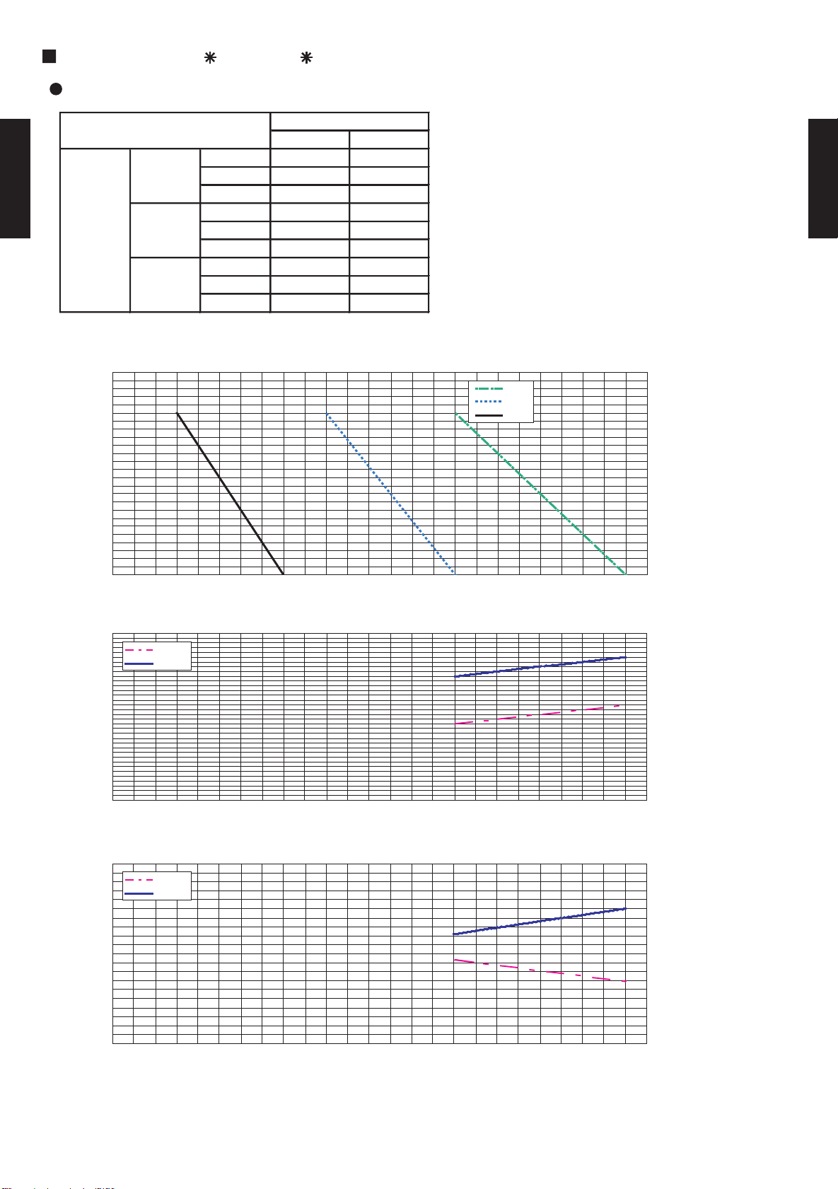
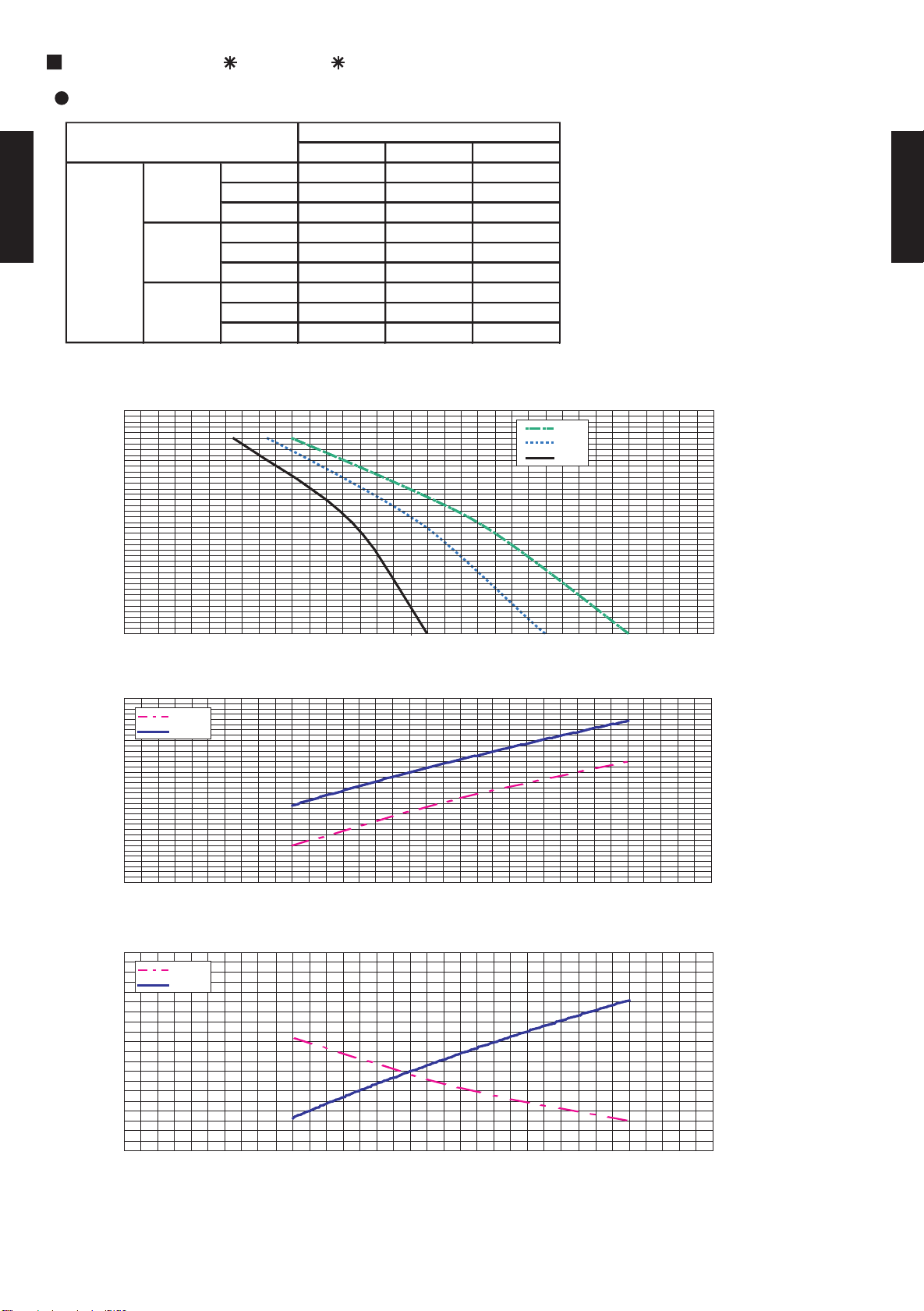
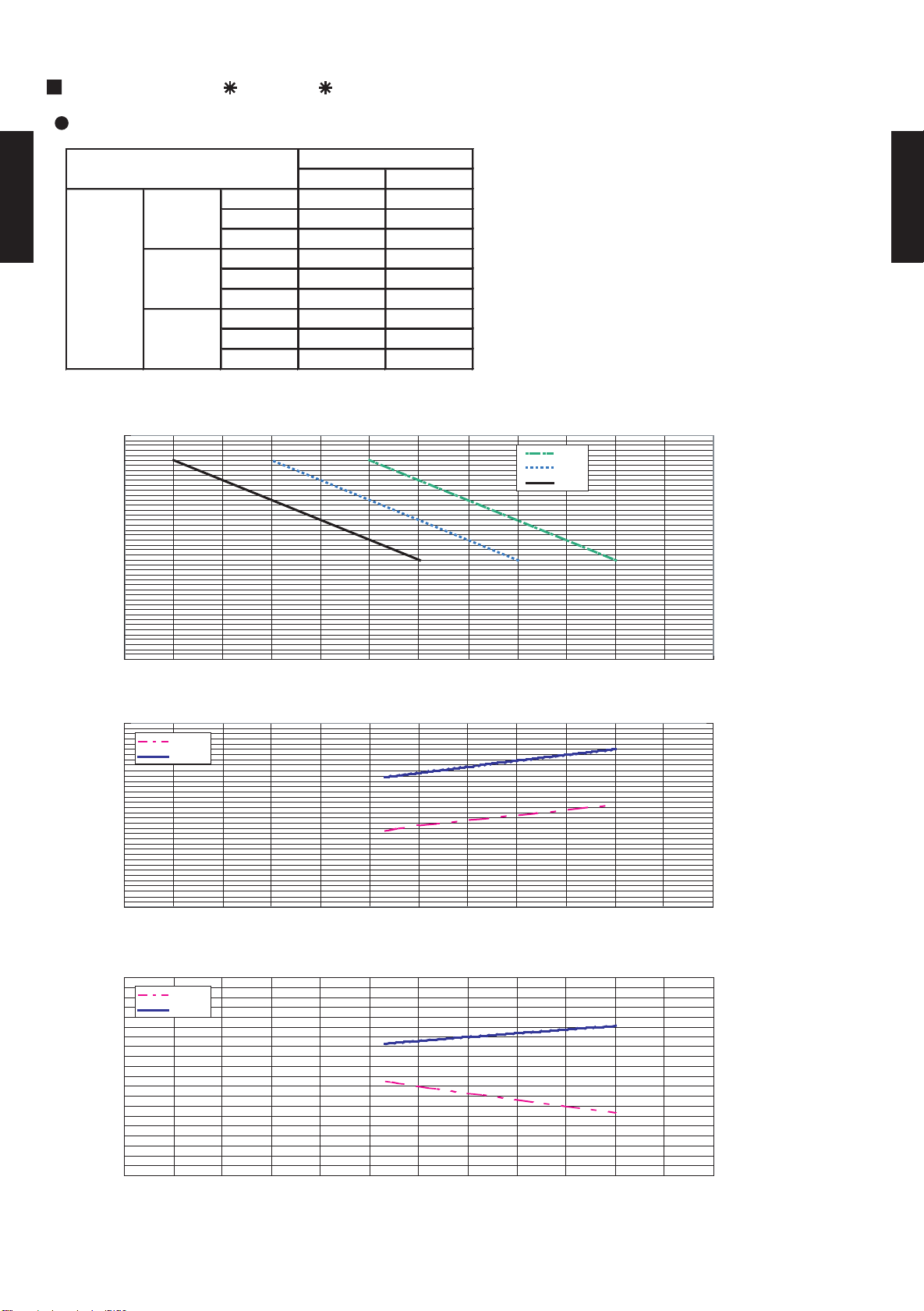
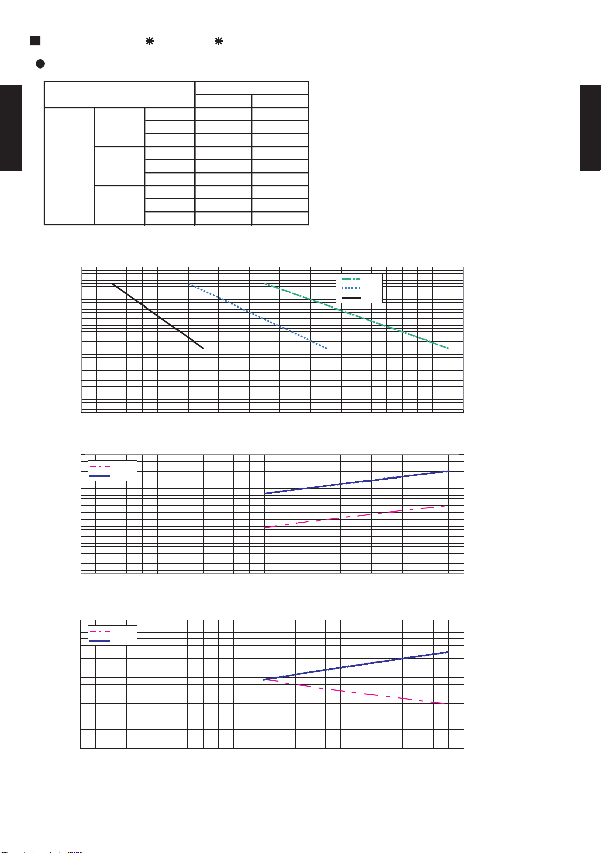
2-8. CAPACITY COMPENSATION FOR PIPE LENGTH
5 7.5 10 15
- - - -
- - - -
8 - 0.993 0.982 0.964
5 1.005 0.995 0.984 0.966
0 1.010 1.000 0.989 0.971
-5 1.010 1.000 0.989 0.971
-8 - 1.000 0.989 0.971
- - - -
- - - -
PIPE LENGTH (m)
Outdoor unit
is
up-side
HEIGHT DIFFERENCE
(m)
HEATING
5 7.5 10 15
- - - -
- - - -
8 - 1.000 0.985 0.952
5 1.010 1.000 0.985 0.952
0 1.010 1.000 0.985 0.952
-5 1.002 0.992 0.977 0.944
-8 - 0.988 0.973 0.941
- - - -
- - - -
PIPE LENGTH (m)
COOLING
HEIGHT DIFFERENCE
(m)
Outdoor unit
is
up-side
Outdoor unit is
bottom-side
AND HEIGHT DIFFERENCE
MODELS:
AR 7U / AO 7U
AR 9U / AO 9U
AR 12U / AO 12U
AR 14U / AO 14U
DUCT TYPE
AR7 - AR18K
COEFFICIENT OF COMPENSATION FOR PIPE LENGTH
COOLING HEATING
1.200
1.150
1.100
1.050
1.000
0.950
0.900
Coefficient of compensation
0.850
0.800
0 5 10 15 20 25 30
1.200
1.150
1.100
1.050
1.000
0.950
0.900
Coefficient of compensation
0.850
0.800
0 5 10 15 20 25 30
Pipe length (m)Pipe length (m)
COEFFICIENT OF COMPENSATION FOR HEIGHT DIFFERENCE
DUCT TYPE
AR7 - AR18K
bottom-side
Outdoor unit is
- (02 - 26) -
Page 28

MODELS:
5 7.5 10 15
8 1.000
-
-
-
-
-
-
-
-
-
-
-
-
-
-
-
-
-
-
0.985 0.952
5 1.010 1.000 0.985 0.952
0 1.010 1.000 0.985 0.952
-5 1.002 0.992 0.977 0.944
-8 0.988 0.973 0.941
COOLING
HEIGHT DIFFERENCE
(m)
Outdoor unit
is
up-side
Outdoor unit is
bottom-side
PIPE LENGTH (m)
COEFFICIENT OF COMPENSATION FOR PIPE LENGTH
DUCT TYPE
1.200
AR7 - AR18K
1.150
1.100
1.050
1.000
0.950
0.900
Coefficient of compensation
0.850
0.800
COEFFICIENT OF COMPENSATION FOR HEIGHT DIFFERENCE
AR 7F / AO 7F
AR 9F / AO 9F
AR 12F / AO 12F
AR 14F / AO 14F
COOLING
0 5 10 15 20 25 30
Pipe length (m)
DUCT TYPE
AR7 - AR18K
- (02 - 27) -
Page 29

MODELS:
5 7.5 10 15 20
- - - - -
- - - - -
8 - 0.993 0.982 0.964 0.946
5 1.005 0.995 0.984 0.966 0.948
0 1.010 1.000 0.989 0.971 0.953
-5 1.010 1.000 0.989 0.971 0.953
-8 - 1.000 0.989 0.971 0.953
- - - - -
- - - - -
PIPE LENGTH (m)
Outdoor unit
is
up-side
HEIGHT DIFFERENCE
(m)
HEATING
5 7.5 10 15 20
- - - - -
-
-
- - - -
8 1.000 0.985 0.952 0.919
5 1.010 1.000 0.985 0.952 0.919
0 1.010 1.000 0.985 0.952 0.919
-5 1.002 0.992 0.977 0.944 0.912
-8 - 0.988 0.973 0.941 0.908
- - - - -
- - - - -
PIPE LENGTH (m)
COOLING
HEIGHT DIFFERENCE
(m)
Outdoor unit
is
up-side
Outdoor unit is
bottom-side
AR 18U / AO 18U
COEFFICIENT OF COMPENSATION FOR PIPE LENGTH
COOLING HEATING
1.200
1.150
1.100
1.050
DUCT TYPE
1.000
AR7 - AR18K
0.950
0.900
Coefficient of compensation
0.850
0.800
0 5 10 15 20 25 30
Pipe length (m)
1.200
1.150
1.100
1.050
1.000
0.950
0.900
Coefficient of compensation
0.850
0.800
0 5 10 15 20 25 30
Pipe length (m)
DUCT TYPE
AR7 - AR18K
COEFFICIENT OF COMPENSATION FOR HEIGHT DIFFERENCE
bottom-side
Outdoor unit is
- (02 - 28) -
Page 30

MODELS:
5 7.5 10 15 20
- - - - -
- - - - -
8 - 1.000 0.985 0.952 0.919
5 1.010 1.000 0.985 0.952 0.919
0 1.010 1.000 0.985 0.952 0.919
-5 1.002 0.992 0.977 0.944 0.912
-8 - 0.988 0.973 0.941 0.908
- - - - -
- - - - -
COOLING
HEIGHT DIFFERENCE (m)
Outdoor unit
is
up-side
Outdoor unit is
bottom-side
PIPE LENGTH (m)
AR 18F / AO 18F
COEFFICIENT OF COMPENSATION FOR PIPE LENGTH
COOLING
1.200
1.150
DUCT TYPE
1.100
AR7 - AR18K
1.050
1.000
0.950
0.900
Coefficient of compensation
0.850
0.800
0 5 1 0 15 20 25 30
Pipe length (m)
DUCT TYPE
AR7 - AR18K
COEFFICIENT OF COMPENSATION FOR HEIGHT DIFFERENCE
- (02 - 29) -
Page 31

2-9. ADDITIONAL CHARGE CALCULATION
MODELS : AR 7F / AO 7F , AR 9F / AO 9F
AR 12F / AO 12F , AR 14F / AO 14F
REFRIGERANT CHARGE
MODEL NAME
DUCT TYPE
AR7 - AR18K
PRECHARGE
ADITIONAL charge
MODELS : AR 7U / AO 7U , AR 9U / AO 9U
AR 12U / AO 12U , AR 14U / AO 14U
MODEL NAME
PRECHARGE
ADITIONAL charge
TYPE
INDOOR
OUTDOOR
REFREGERANT TYPE
CHARGELESS PIPE LENGTH
AMOUNT
10m
15m
20m
g/m
REFRIGERANT CHARGE
TYPE
INDOOR
OUTDOOR
REFREGERANT TYPE
CHARGELESS PIPE LENGTH
AMOUNT
10m
15m
20m
g/m
DUCTED MODEL
COOLING TYPE
AR*7F AR*9F AR*12F AR*14F AR*18F
AO*7F AO*9F AO*12F AO*14F AO*18F
R410A
m 7.5 7.5 7.5 7.5 7.5
550 600 800 900 900
550+38 600+38 800+38 900+38 900+50
g
550+113 600+113 800+113 900+113 900+150
- - - - 900+250
15 15 15 15 20
DUCTED MODEL
HEAT PUMP TYPE
AR*7U AR*9U AR*12U AR*14U AR*18U
AO*7U AO*9U AO*12U AO*14U AO*18U
R410A
m 7.5 7.5 7.5 7.5 7.5
650 750 850 1000 1400
650+38 750+38 850+38 1000+38 1400+50
g
650+113 750+113 850+113 1000+113 1400+150
- - - - 1400+250
15 15 15 15 20
DUCT TYPE
AR7 - AR18K
- (02 - 30) -
Page 32
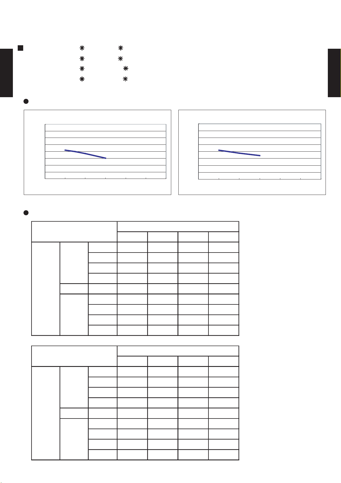
2-10. OPERATION RANGE
Indoor unit Outdoor unit Mode Indoor unit Indoor humidity Outdoor unit
Cooling
Dry
18 to 32 °C 80% or less 21 to 43 °C
Indoor unit Outdoor unit Mode Indoor unit Indoor humidity Outdoor unit
Indoor unit Outdoor unit Mode Indoor unit Indoor humidity Outdoor unit
Cooling
Dry
18 to 32 °C 0 to 43 °C
Heating
16 to 30 °C -6 to 24 °C
80% or less
80% or less
0 to 43 °C
Model
Operation Range
AR*18F
AO*18F
Cooling
Dry
18 to 32 °C
Model
Operation Range
Model
Operation Range
AR*7F
AR*9F
AR*12F
AR*14F
DUCT TYPE
AR7 - AR18K
AR*7U
AR*9U
AR*12U
AR*14U
AR*18U
AO*7F
AO*9F
AO*12F
AO*14F
AO*7U
AO*9U
AO*12U
AO*14U
AO*18U
DUCT TYPE
AR7 - AR18K
- (02 - 31) -
Page 33
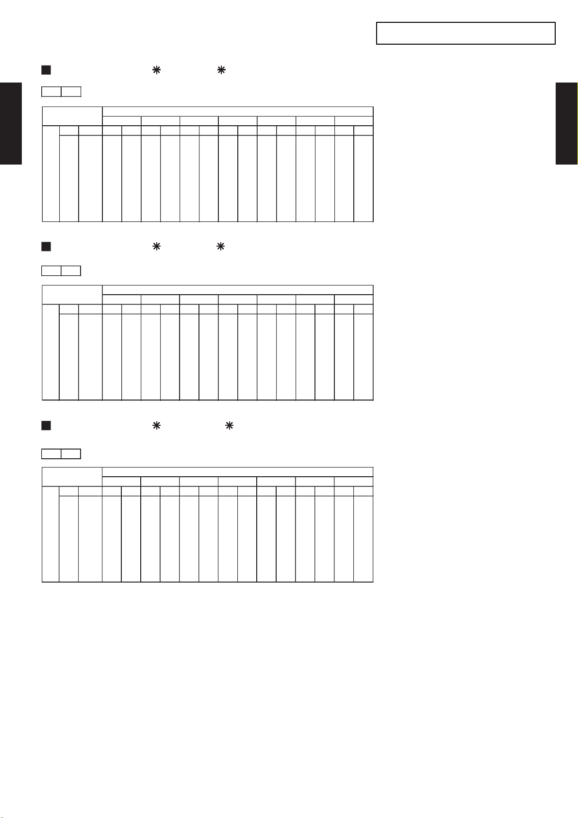
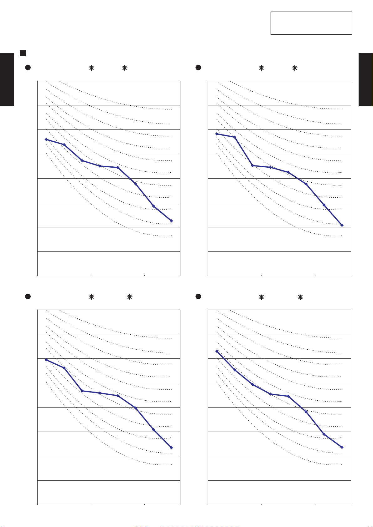
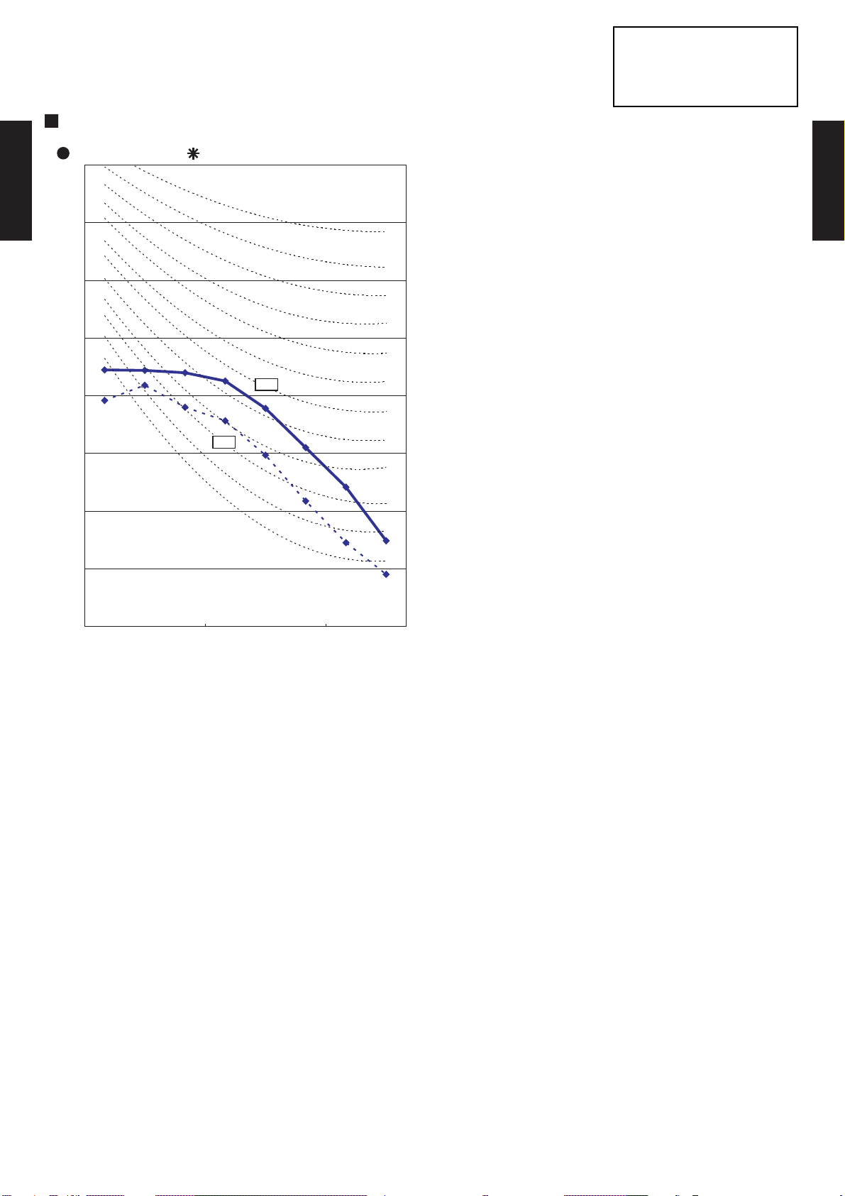
2-11. FAN PERFORMANCE AND AIR FLOW
0 20
3
340 290
l/s 94 81
CFM 200 171
3
320 270
l/s 89 75
CFM 188 159
3
300 250
l/s 83 69
CFM 177 147
230V
Static pressure (Pa)
FAN SPEED
Hi
Med
Low
2-11-1. NORMAL MODE
MODELS : AR 7F, AR 7U
230V
DUCT TYPE
AR7 - AR18K
Q-h Characteris tic curve
25
20
Hi
Med
Low
DUCT TYPE
AR7 - AR18K
15
10
5
STATIC PRESSURE(Pa)
0
240 260 280 300 320 340 360
COOLING
105.0
100.0
95.0
90.0
85.0
80.0
75.0
Cooling capacity(%)
70.0
240 260 280 300 320 340 360
Air temp
Capacity
HEATING
105.0
103.0
101.0
99.0
97.0
95.0
93.0
91.0
89.0
Heating capacity(%)
87.0
85.0
240 260 280 300 320 340 360
Air temp
Capacity
16.0
15.0
14.0
13.0
12.0
11.0
10.0
9.0
55.0
53.0
51.0
49.0
47.0
45.0
43.0
41.0
39.0
37.0
35.0
°C)
Air temperature(
°C)
Air temperature(
Testcondition:NofilterandFanmode.
AIR FLOW (m3/h)
- (02 - 32) -
Page 34

MODELS : AR 9F, AR 9U
0 20
3
420 380
l/s 117 106
CFM 247 224
3
390 350
l/s 108 97
CFM 230 206
3
360 330
l/s 100 92
CFM 212 194
230V
FAN SPEED
Hi
Med
Low
Static pressure (Pa)
230V
DUCT TYPE
AR7 - AR18K
DUCT TYPE
AR7 - AR18K
Q-h Characteris tic curve
25
Hi
20
15
10
5
0
320 340 360 380 400 420
105.0
100.0
95.0
90.0
85.0
80.0
75.0
Cooling capacity(%) STATIC PRESSURE(Pa)
70.0
320 340 360 380 400 420
Air temp
Capacity
Med
Low
COOLING
COOLING
16.0
15.0
14.0
13.0
12.0
11.0
10.0
9.0
°C)
Air temperature(
105.0
103.0
101.0
99.0
97.0
95.0
93.0
91.0
89.0
Heating capacity(%)
87.0
85.0
320 340 360 380 400 420
Testcondition:NofilterandFanmode.
Air temp
Capacity
AIR FLOW (m3/h)
- (02 - 33) -
HEATING
55.0
53.0
51.0
49.0
47.0
45.0
43.0
41.0
39.0
37.0
35.0
°C)
Air temperature(
Page 35
MODELS : AR 12F, AR 12U
0 20
3
500 430
l/s 139 119
CFM 294 253
3
450 390
l/s 125 108
CFM 265 230
3
400 340
l/s 111 94
CFM 235 200
FAN SPEED
Hi
Med
Low
Static pressure (Pa)
230V
230V
DUCT TYPE
AR7 - AR18K
DUCT TYPE
AR7 - AR18K
Q-h Characteris tic curve
25
20
15
10
5
0
330 380 430 480
105.0
100.0
95.0
90.0
85.0
80.0
75.0
Cooling capacity(%) STATIC PRESSURE(Pa)
70.0
330 380 430 480
Air temp
Capacity
Hi
Med
Low
COOLING
COOLING
16.0
15.0
14.0
13.0
12.0
11.0
10.0
9.0
°C)
Air temperature(
105.0
103.0
101.0
99.0
97.0
95.0
93.0
91.0
89.0
Heating capacity(%)
87.0
85.0
330 380 430 480
Testcondition:NofilterandFanmode.
Air temp
Capacity
AIR FLOW (m3/h)
- (02 - 34) -
HEATING
55.0
53.0
51.0
49.0
47.0
45.0
43.0
41.0
39.0
37.0
35.0
°C)
Air temperature(
Page 36
MODELS : AR 14F, AR 14U
0 20
3
640 560
l/s 178 156
CFM 377 330
3
560 500
l/s 156 139
CFM 330 294
3
480 430
l/s 133 119
CFM 283 253
230V
FAN SPEED
Hi
Med
Low
Static pressure (Pa)
230V
DUCT TYPE
AR7 - AR18K
DUCT TYPE
AR7 - AR18K
Q-h Characteris tic curve
25
Hi
20
15
10
5
0
400 450 500 550 600 650
Med
Low
COOLING
COOLING
105.0
100.0
95.0
90.0
85.0
80.0
75.0
Cooling capacity(%) STATIC PRESSURE(Pa)
70.0
400 450 500 550 600 650
Air temp
Capacity
16.0
15.0
14.0
13.0
12.0
11.0
10.0
9.0
°C)
Air temperature(
105.0
103.0
101.0
99.0
97.0
95.0
93.0
91.0
89.0
Heating capacity(%)
87.0
85.0
400 450 500 550 600 650
Testcondition:NofilterandFanmode.
Air temp
Capacity
AIR FLOW (m3/h)
- (02 - 35) -
HEATING
55.0
53.0
51.0
49.0
47.0
45.0
43.0
41.0
39.0
37.0
35.0
°C)
Air temperature(
Page 37
MODELS : AR 18F, AR 18U
0 40 70
3
1000 820 600
l/s 278 228 167
CFM 589 483 353
3
900 750 570
l/s 250 208 158
CFM 530 441 335
3
760 670 530
l/s 211 186 147
CFM 447 394 312
230V
FAN SPEED
Hi
Med
Low
Static pressure (Pa)
230V
DUCT TYPE
AR7 - AR18K
DUCT TYPE
AR7 - AR18K
Q-h Characteris tic curve
80
70
60
50
40
30
20
10
0
400 500 600 700 800 900 1000 1100
Hi
Med
Low
COOLING
COOLING
105.0
100.0
95.0
90.0
85.0
80.0
75.0
Cooling capacity(%) STATIC PRESSURE(Pa)Heating capacity(%)
70.0
400 500 600 700 800 900 1,000 1,100
Air temp
Capacity
16.0
15.0
14.0
13.0
12.0
11.0
10.0
9.0
°C)
Air temperature(
105.0
103.0
101.0
99.0
97.0
95.0
93.0
91.0
89.0
87.0
85.0
400 500 600 700 800 900 1,000 1,100
Testcondition:NofilterandFanmode.
Air temp
Capacity
AIR FLOW (m3/h)
- (02 - 36) -
HEATING
55.0
53.0
51.0
49.0
47.0
45.0
43.0
41.0
39.0
37.0
35.0
°C)
Air temperature(
Page 38
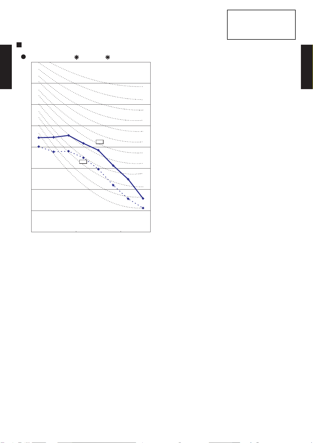
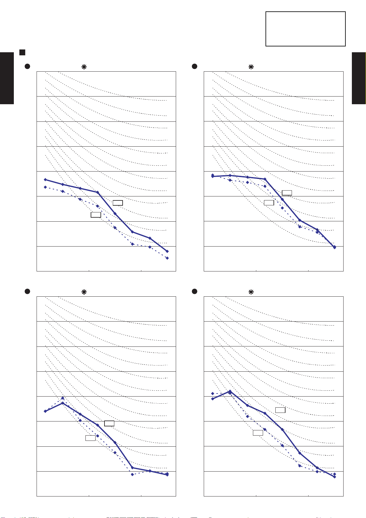
2-11-2. HIGH STATIC MODE
20 40
3
340 290
l/s 94 81
CFM 200 171
3
320 270
l/s 89 75
CFM 188 159
3
300 250
l/s 83 69
CFM 177 147
230V
Static pressure (Pa)
FAN SPEED
Hi
Med
Low
MODELS : AR 7F, AR 7U
230V
DUCT TYPE
AR7 - AR18K
Q-h Characteris tic curve
45
40
35
30
25
20
15
10
5
0
240 260 280 300 320 340 360
Hi
Med
Low
DUCT TYPE
AR7 - AR18K
105.0
COOLING
100.0
95.0
90.0
85.0
80.0
75.0
Cooling capacity(%) STATIC PRESSURE(Pa)
70.0
240 260 280 300 320 340 360
105.0
103.0
101.0
99.0
97.0
95.0
93.0
91.0
89.0
Heating capacity(%)
87.0
85.0
240 260 280 300 320 340 360
Air temp
Capacity
HEATING
Air temp
Capacity
16.0
15.0
14.0
13.0
12.0
11.0
10.0
9.0
55.0
53.0
51.0
49.0
47.0
45.0
43.0
41.0
39.0
37.0
35.0
°C)
Air temperature(
°C)
Air temperature(
Testcondition:NofilterandFanmode.
AIR FLOW (m3/h)
- (02 - 37) -
Page 39

MODELS : AR 9F, AR 9U
20 40
3
420 360
l/s 117 100
CFM 247 212
3
390 330
l/s 108 92
CFM 230 194
3
360 310
l/s 100 86
CFM 212 182
230V
FAN SPEED
Hi
Med
Low
Static pressure (Pa)
230V
DUCT TYPE
AR7 - AR18K
Q-h Characteris tic curve
45
40
35
30
25
20
15
10
5
0
300 320 340 360 380 400 420
Hi
Med
Low
DUCT TYPE
AR7 - AR18K
105.0
100.0
95.0
90.0
85.0
80.0
75.0
Cooling capacity(%) STATIC PRESSURE(Pa)
70.0
300 320 340 360 380 400 420
105.0
103.0
101.0
99.0
97.0
95.0
93.0
91.0
89.0
Heating capacity(%)
87.0
85.0
300 320 340 360 380 400 420
Testcondition:NofilterandFanmode.
Air temp
Capacity
Air temp
Capacity
AIR FLOW (m3/h)
- (02 - 38) -
COOLING
HEATING
16.0
15.0
14.0
13.0
12.0
11.0
10.0
9.0
55.0
53.0
51.0
49.0
47.0
45.0
43.0
41.0
39.0
37.0
35.0
°C)
Air temperature(
°C)
Air temperature(
Page 40

MODELS : AR 12F, AR 12U
20 40
3
500 400
l/s 139 111
CFM 294 235
3
450 370
l/s 125 103
CFM 265 218
3
400 330
l/s 111 92
CFM 235 194
FAN SPEED
Hi
Med
Low
Static pressure (Pa)
230V
230V
DUCT TYPE
AR7 - AR18K
Q-h Characteris tic curve
45
40
35
30
25
20
15
10
5
0
320 370 420 470 520
Hi
Med
Low
DUCT TYPE
AR7 - AR18K
105.0
100.0
95.0
90.0
85.0
80.0
75.0
Cooling capacity(%) STATIC PRESSURE(Pa)
70.0
320 370 420 470 520
105.0
103.0
101.0
99.0
97.0
95.0
93.0
91.0
89.0
Heating capacity(%)
87.0
85.0
320 370 420 470 520
Testcondition:NofilterandFanmode.
Air temp
Capacity
Air temp
Capacity
AIR FLOW (m3/h)
- (02 - 39) -
COOLING
HEATING
16.0
15.0
14.0
13.0
12.0
11.0
10.0
9.0
55.0
53.0
51.0
49.0
47.0
45.0
43.0
41.0
39.0
37.0
35.0
°C)
Air temperature(
°C)
Air temperature(
Page 41
MODELS : AR 14F, AR 14U
20 40
3
640 520
l/s 178 144
CFM 377 306
3
560 470
l/s 156 131
CFM 330 277
3
480 420
l/s 133 117
CFM 283 247
230V
FAN SPEED
Hi
Med
Low
Static pressure (Pa)
230V
DUCT TYPE
AR7 - AR18K
Q-h Characteris tic curve
45
40
35
30
25
20
15
10
5
0
400 450 500 550 600 650
Hi
Med
Low
DUCT TYPE
AR7 - AR18K
105.0
100.0
95.0
90.0
85.0
80.0
75.0
Cooling capacity(%) STATIC PRESSURE(Pa)
70.0
400 450 500 550 600 650
105.0
103.0
101.0
99.0
97.0
95.0
93.0
91.0
89.0
Heating capacity(%)
87.0
85.0
400 450 500 550 600 650
Testcondition:NofilterandFanmode.
Air temp
Capacity
Air temp
Capacity
AIR FLOW (m3/h)
- (02 - 40) -
COOLING
HEATING
16.0
15.0
14.0
13.0
12.0
11.0
10.0
9.0
55.0
53.0
51.0
49.0
47.0
45.0
43.0
41.0
39.0
37.0
35.0
°C)
Air temperature(
°C)
Air temperature(
Page 42

0 40
3
820 700
l/s 228 194
CFM 483 412
3
750 650
l/s 208 181
CFM 441 383
3
670 590
l/s 186 164
CFM 394 347
230V
FAN SPEED
Hi
Med
Low
Static pressure (Pa)
2-11-3. LOW STATIC MODE
MODELS : AR 18F, AR 18U
230V
DUCT TYPE
AR7 - AR18K
45
40
35
30
25
20
15
10
5
0
550 600 650 700 750 800 850
Q-h Characteris tic curve
Hi
Med
Low
DUCT TYPE
AR7 - AR18K
105.0
COOLING
100.0
95.0
90.0
85.0
80.0
75.0
Cooling capacity(%) STATIC PRESSURE(Pa)
70.0
550 600 650 700 750 800 850
105.0
103.0
101.0
99.0
97.0
95.0
93.0
91.0
89.0
Heating capacity(%)
87.0
85.0
550 600 650 700 750 800 850
Air temp
Capacity
HEATING
Air temp
Capacity
16.0
15.0
14.0
13.0
12.0
11.0
10.0
9.0
55.0
53.0
51.0
49.0
47.0
45.0
43.0
41.0
39.0
37.0
35.0
°C)
Air temperature(
°C)
Air temperature(
Testcondition:NofilterandFanmode.
AIR FLOW (m3/h)
- (02 - 41) -
Page 43
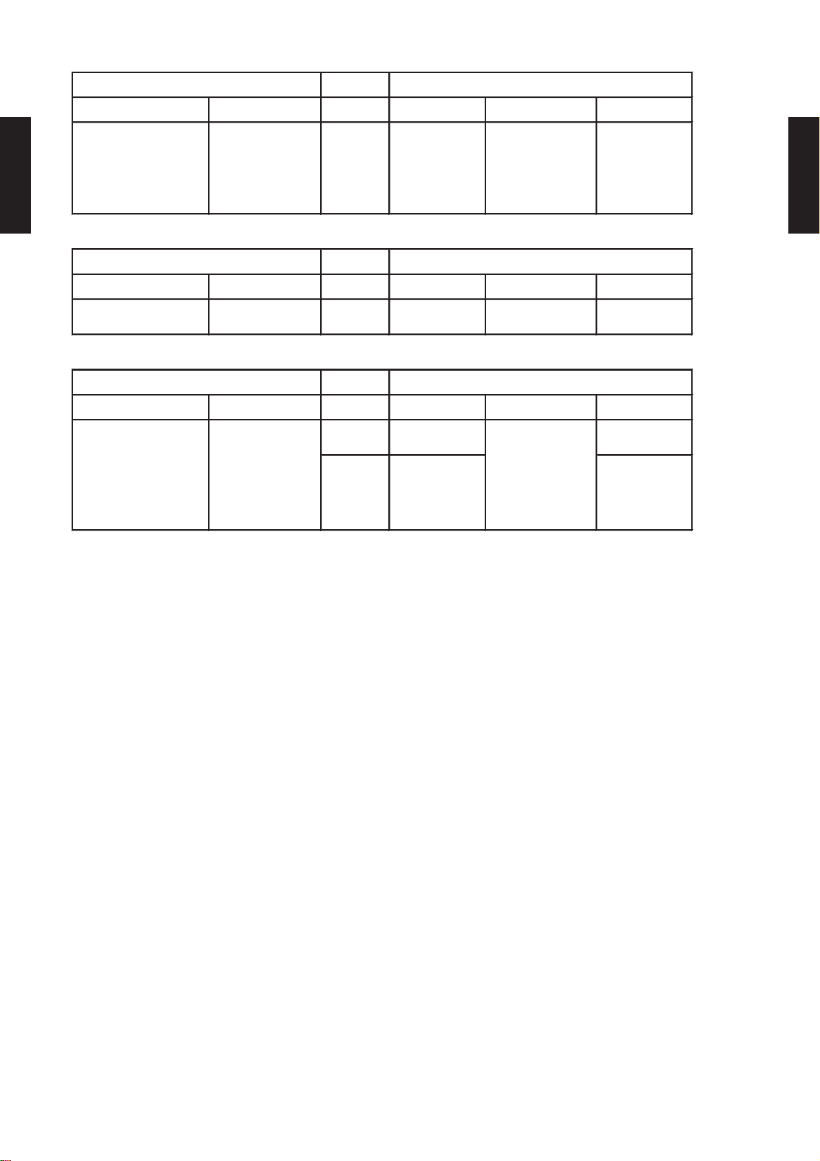
2-12. NOISE LEVEL CURVE
NC‑20
NC‑30
NC‑40
NC‑50
NC‑60
NC‑70
NC‑20
NC‑30
NC‑40
NC‑50
NC‑60
NC‑70
NC‑20
NC‑30
NC‑40
NC‑50
NC‑60
NC‑70
NC‑20
NC‑30
NC‑40
NC‑50
NC‑60
NC‑70
2-12-1. OUTDOOR UNIT
COOLING
MODELS : AO 7F, AO 7U MODELS : AO 9F, AO 9U
Condition
Voltage : 230V /50Hz
80
DUCT TYPE
AR7 - AR18K
70
60
50
40
30
Octave band sound pressure level, dB:(0dB=0.0002µbar)
20
10
80
DUCT TYPE
70
60
50
40
30
Octave band sound pressure level, dB:(0dB=0.0002µbar)
20
10
AR7 - AR18K
0
63
125 250 500
1000 2000 4000 800 0
0
63
125 250 500
1000 2000 4000 800 0
Octave band center frequency,Hz Octave band center frequency,Hz
MODELS : AO 12F, AO 12U MODELS : AO 14F, AO 14U
80
70
60
50
40
30
Octave band sound pressure level, dB:(0dB=0.0002µbar)
20
80
70
60
50
40
30
Octave band sound pressure level, dB:(0dB=0.0002µbar)
20
10
0
63
125 250 500
1000 2000 4000 800 0
10
0
63
125 250 500
1000 2000 4000 800 0
Octave band center frequency,Hz Octave band center frequency,Hz
- (02 - 42) -
Page 44

Condition
NC‑20
NC‑30
NC‑40
NC‑50
NC‑60
NC‑70
Voltage : 230V /50Hz
COOLING
MODELS : AO 18F, AO 18U
80
DUCT TYPE
AR7 - AR18K
70
60
50
40
DUCT TYPE
AR7 - AR18K
30
Octave band sound pressure level, dB:(0dB=0.0002µbar)
20
10
0
63
125 250 500
Octave band center frequency,Hz
1000 2000 4000 800 0
- (02 - 43) -
Page 45

HEATING
NC‑20
NC‑30
NC‑40
NC‑50
NC‑60
NC‑70
NC‑20
NC‑30
NC‑40
NC‑50
NC‑60
NC‑70
NC‑20
NC‑30
NC‑40
NC‑50
NC‑60
NC‑70
NC‑20
NC‑30
NC‑40
NC‑50
NC‑60
NC‑70
MODEL : AO 7U MODEL : AO 9U
80
80
Condition
Voltage : 230V /50Hz
DUCT TYPE
AR7 - AR18K
70
60
50
40
30
Octave band sound pressure level, dB:(0dB=0.0002µbar)
20
10
0
63
125 250 500
1000 2000 4000 800 0
70
60
50
40
30
Octave band sound pressure level, dB:(0dB=0.0002µbar)
20
10
0
63
125 250 500
1000 2000 4000 800 0
DUCT TYPE
AR7 - AR18K
Octave band center frequency,Hz Octave band center frequency,Hz
MODEL : AO 12U MODEL : AO 14U
80
70
60
50
40
30
Octave band sound pressure level, dB:(0dB=0.0002µbar)
20
10
80
70
60
50
40
30
Octave band sound pressure level, dB:(0dB=0.0002µbar)
20
10
0
63
125 250 500
1000 2000 4000 800 0
0
63
125 250 500
1000 2000 4000 800 0
Octave band center frequency,Hz Octave band center frequency,Hz
- (02 - 44) -
Page 46

HEATING
NC‑20
NC‑30
NC‑40
NC‑50
NC‑60
NC‑70
MODEL : AO 18U
80
Condition
Voltage : 230V /50Hz
DUCT TYPE
AR7 - AR18K
70
60
50
40
dB:(0dB=0.0002μbar)
30
Octave band sound pressure level, dB:(0dB=0.0002µbar)
20
10
0
63
125 250 500
Octave band center frequency,Hz
1000 2000 4000 800 0
DUCT TYPE
AR7 - AR18K
- (02 - 45) -
Page 47

NC‑20
NC‑30
NC‑40
NC‑50
NC‑60
NC‑70
HIGH
LOW
NC‑20
NC‑30
NC‑40
NC‑50
NC‑60
NC‑70
HIGH
LOW
NC‑20
NC‑30
NC‑40
NC‑50
NC‑60
NC‑70
HIGH
LOW
C‑N20
NC‑30
NC‑40
NC‑50
NC‑60
NC‑70
HIGH
LOW
2-12-2. INDOOR UNIT
COOLING
MODELS : AR 7F,AR 7U MODELS : AR 9F, AR 9U
80
Condition
Fan speed : High,Low
Voltage : 230V /50Hz
Static pressure : 0Pa
80
DUCT TYPE
AR7 - AR18K
70
60
50
40
30
Octave band sound pressure level, dB:(0dB=0.0002µbar)
20
10
0
63
125 250 500
1000 2000 4000 800 0
70
60
50
40
30
Octave band sound pressure level, dB:(0dB=0.0002µbar)
20
10
0
63
125 250 500
1000 2000 4000 800 0
DUCT TYPE
AR7 - AR18K
Octave band center frequency,Hz Octave band center frequency,Hz
MODELS : AR 12F, AR 12U MODELS : AR 14F, AR 14U
80
70
60
50
40
30
Octave band sound pressure level, dB:(0dB=0.0002µbar)
20
10
80
70
60
50
40
30
Octave band sound pressure level, dB:(0dB=0.0002µbar)
20
10
0
63
125 250 500
1000 2000 4000 800 0
0
63
125 250 500
1000 2000 4000 800 0
Octave band center frequency,Hz Octave band center frequency,Hz
- (02 - 46) -
Page 48
COOLING
NC‑20
NC‑30
NC‑40
NC‑50
NC‑60
NC‑70
HIGH
LOW
MODELS : AR 18F, AR 18U
80
Condition
Fan speed : High,Low
Voltage : 230V /50Hz
Static pressure : 0Pa
DUCT TYPE
AR7 - AR18K
70
60
50
40
30
Octave band sound pressure level, dB:(0dB=0.0002µbar)
20
10
0
63 125 250 500 1000 2000 4 000 8000
Octave band center frequency,Hz
DUCT TYPE
AR7 - AR18K
- (02 - 47) -
Page 49
HEATING
NC‑20
NC‑30
NC‑40
NC‑50
NC‑60
NC‑70
HIGH
LOW
NC‑20
NC‑30
NC‑40
NC‑50
NC‑60
NC‑70
HIGH
LOW
NC‑20
NC‑30
NC‑40
NC‑50
NC‑60
NC‑70
HIGH
LOW
NC‑20
NC‑30
NC‑40
NC‑50
NC‑60
NC‑70
HIGH
LOW
Condition
Fan speed : High, Low
Voltage : 230V /50Hz
Static pressure : 0Pa
MODEL : AR 7U MODEL : AR 9U
80
DUCT TYPE
AR7 - AR18K
70
60
50
40
30
Octave band sound pressure level, dB:(0dB=0.0002µbar)
20
10
80
70
60
50
40
30
Octave band sound pressure level, dB:(0dB=0.0002µbar)
20
10
DUCT TYPE
AR7 - AR18K
0
63
125 250 500
1000 2000 4000 8000
0
63
125 250 500
Octave band center frequency,Hz Octave band center frequency,Hz
MODEL : AR 12U MODEL : AR 14U
80
70
60
50
40
30
Octave band sound pressure level, dB:(0dB=0.0002µbar)
20
80
70
60
50
40
30
Octave band sound pressure level, dB:(0dB=0.0002µbar)
20
1000 2000 4000 8000
10
0
63
125 250 500
1000 2000 4000 8000
10
0
63
125 250 500
1000 2000 4000 8000
Octave band center frequency,Hz Octave band center frequency,Hz
- (02 - 48) -
Page 50
HEATING
NC‑20
NC‑30
NC‑40
NC‑50
NC‑60
NC‑70
HIGH
LOW
MODEL : AR 18U
80
Condition
Fan speed : High, Low
Voltage : 230V /50Hz
Static pressure : 0Pa
DUCT TYPE
AR7 - AR18K
70
60
50
40
30
Octave band sound pressure level, dB:(0dB=0.0002µbar)
20
10
0
63
125 250 500
Octave band center frequency,Hz
1000 2000 4000 8000
DUCT TYPE
AR7 - AR18K
- (02 - 49) -
Page 51
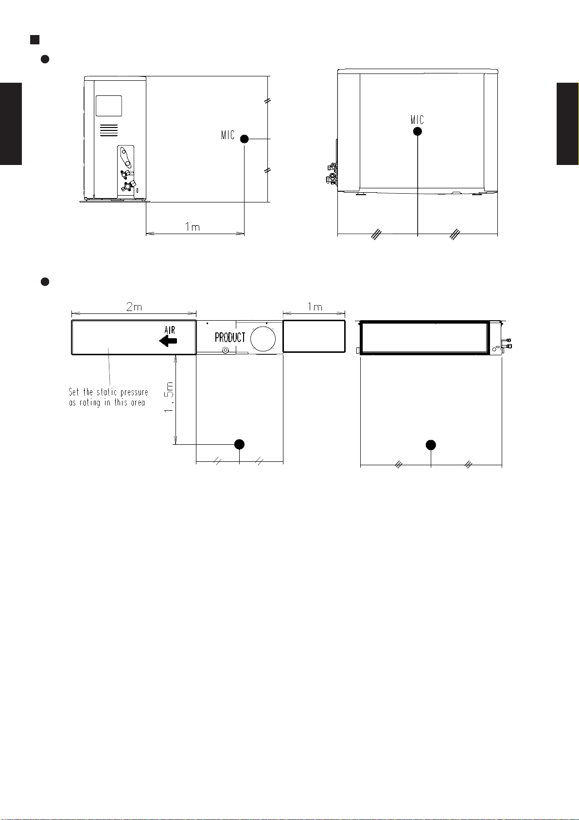
SOUND LEVEL CHECK POINT
OUTDOOR UNIT
DUCT TYPE
AR7 - AR18K
INDOOR UNIT
DUCT TYPE
AR7 - AR18K
- (02 - 50) -
Page 52
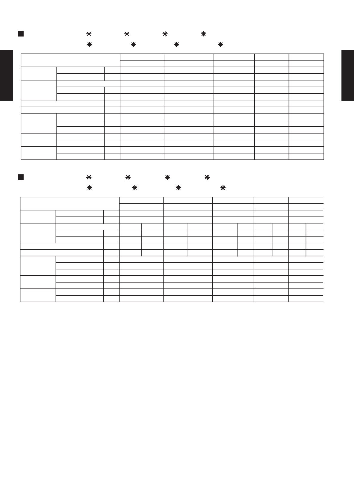
2-13. ELECTRIC CHARACTERISTICS
Voltage V
Hz
Current A
Input kW
A
A
MFA A
Power Cable
mm
2
*2)Limited wiring length m
Input kW
FLA A
Input kW
FLA A
0.99
0.057
0.16
0.035361.51019.5
5.0
0.76
1.51021
6.5
0.057
0.21
0.0442815307.6
1.24
0.057
0.15
0.030
32
0.057
0.20
0.045273.7
4.6
6.3
2.01531
8.9
1.39
5.5
2.0
Cooling
Cooling
Cooling
Cooling
50505050230
230
230
230
AR*9F
AO*9F
AR*7F
AO*7F
AR*14F
AO*14F
AR*12F
AO*12F
0.24
0.24
0.24
0.24
0.970
0.40
0.148
0.73
39202.5
24
Cooling
9
2.03
12.8
AR*18F
AO*18F
230
50
Model Name
Outdoor Fan Motor
Indoor Fan Motor
*1) Wiring Spec
Mode
Rated Value
Power Supply
Max Operating Current
Starting Current
Voltage V
Hz
Cooling Heating Cooling Heating Cooling Heating Cooling Heating Cooling Heating
Current A 3.6 3.6 4.4 4.5 5.5 5.4 6.3 6.0 8.8 8.7
Input kW 0.76 0.76 0.96 0.96 1.24 1.21 1.42 1.35 1.92 1.87
A 5.1 5.2 6.1 6.2 7.6 7.5 9.2 8.3 12.3 12.0
A 19.5 19.5 21 21 30 30 31 31 39 39
MFA A
Power Cable
mm
2
*2)Limited wiring length m
Input kW
FLA A
Input kW
FLA A
0.23
0.23
0.23
0.73
0.15
0.20
0.40
Outdoor Fan Motor
0.057
0.057
0.057
0.057
0.148
0.23
26
25
Indoor Fan Motor
0.035
0.044
0.030
0.045
0.970
0.16
0.21
15201.5
1.5
2.0
2.0
2.5
*1) Wiring Spec
101015
362932
Rated Value
Mode
Max Operating Current
Starting Current
230
230
5050505050
AR*12U
AR*14U
AR*18U
AO*7U
AO*9U
AO*12U
AO*14U
AO*18U
230
Power Supply
230
230
Model Name
AR*7U
AR*9U
MODELS : AR 7F / AO 7F , AR 9F / AO 9F
AR 12F / AO 12F , AR 14F / AO 14F
DUCT TYPE
AR7 - AR18K
MODELS : AR 7U / AO 7U , AR 9U / AO 9U
AR 12U / AO 12U , AR 14U / AO 14U
DUCT TYPE
AR7 - AR18K
*1) Wiring Spec : Selected Sample (Selected based on Japan Electrotechnical Standard and Codes Committee E0005)
*2) Limited Wiring length : This is the wiring length in case voltage descent is less than 2%.
When the wiring length becomes long, please select the wiring of a more larger diameter.
MFA: Main Fuse (Circuit breaker) Current
FLA: Full Load Amp.
- (02 - 51) -
Page 53

2-14. SAFETY DEVICE
PROTECTION FORM
AR*7F AR*9F AR*12F AR*14F AR*18F
PROTECTION FORM
AO*7F AO*9F AO*12F AO*14F AO*18F
0FF 150±5°C
(16.5A/25°C)
(6A/80°C)
ON 69±11°C
0FF 145±5°C
(16.5A/25°C)
(7A/80°C)
ON 69±11°C
0FF 150±5°C
(23.5A/25°C)
(9.6A/80°C)
ON 69±11°C
0FF 160±5°C
(25.5A/25°C)
(10.7A/80°C)
ON 69±11°C
0FF 150±5°C
(30A/25°C)
(13A/80°C)
ON 69±11°C
PROTECTION FORM
AR*7U AR*9U AR*12U AR*14U AR*18U
PROTECTION FORM
AO*7U AO*9U AO*12U AO*14U AO*18U
FUSE
(SIDE OF POWER SUPPLY
0FF 150±5°C
(16.5A/25°C)
(6A/80°C)
ON 69±11°C
0FF 145±5°C
(16.5A/25°C)
(7A/80°C)
ON 69±11°C
0FF 150±5°C
(23.5A/25°C)
(9.6A/80°C)
ON 69±11°C
0FF 160±5°C
(25.5A/25°C)
(10.7A/80°C)
ON 69±11°C
0FF 150±5°C
(30A/25°C)
(13A/80°C)
ON 69±11°C
COOLING MODEL
OUTDOOR UNIT
MODEL NAME
FAN MOTOR PROTECTOR THERMAL PROTECTOR 140°C±5°C OFF 140°C±5°C OFF 140°C±5°C OFF 140°C±5°C OFF 150°C±5°C OFF
COMPRESSOR -
DUCT TYPE
AR7 - AR18K
INDOOR UNIT
MODEL NAME
PCB FUSE - 3.15A 250V 3.15A 250V 3.15A 250V 3.15A 250V 3.15A 250V
FAN MOTOR PROTECTOR THERMAL PROTECTOR 150°C±5°C OFF 150°C±5°C OFF 150°C±5°C OFF 150°C±5°C OFF 150°C±5°C OFF
HEAT PUMP MODEL
OUTDOOR UNIT
MODEL NAME
FUSE ON MAIN PCB - - - - - 3.15A 250V
FAN MOTOR PROTECTOR THERMAL PROTECTOR 140°C±5°C OFF 140°C±5°C OFF 140°C±5°C OFF 140°C±5°C OFF 150°C±5°C OFF
- - - - - -
DUCT TYPE
AR7 - AR18K
COMPRESSOR -
INDOOR UNIT
MODEL NAME
PCB FUSE - 3.15A 250V 3.15A 250V 3.15A 250V 3.15A 250V 3.15A 250V
FAN MOTOR PROTECTOR THERMAL PROTECTOR 150°C±5°C OFF 150°C±5°C OFF 150°C±5°C OFF 150°C±5°C OFF 150°C±5°C OFF
- (02 - 52) -
Page 54
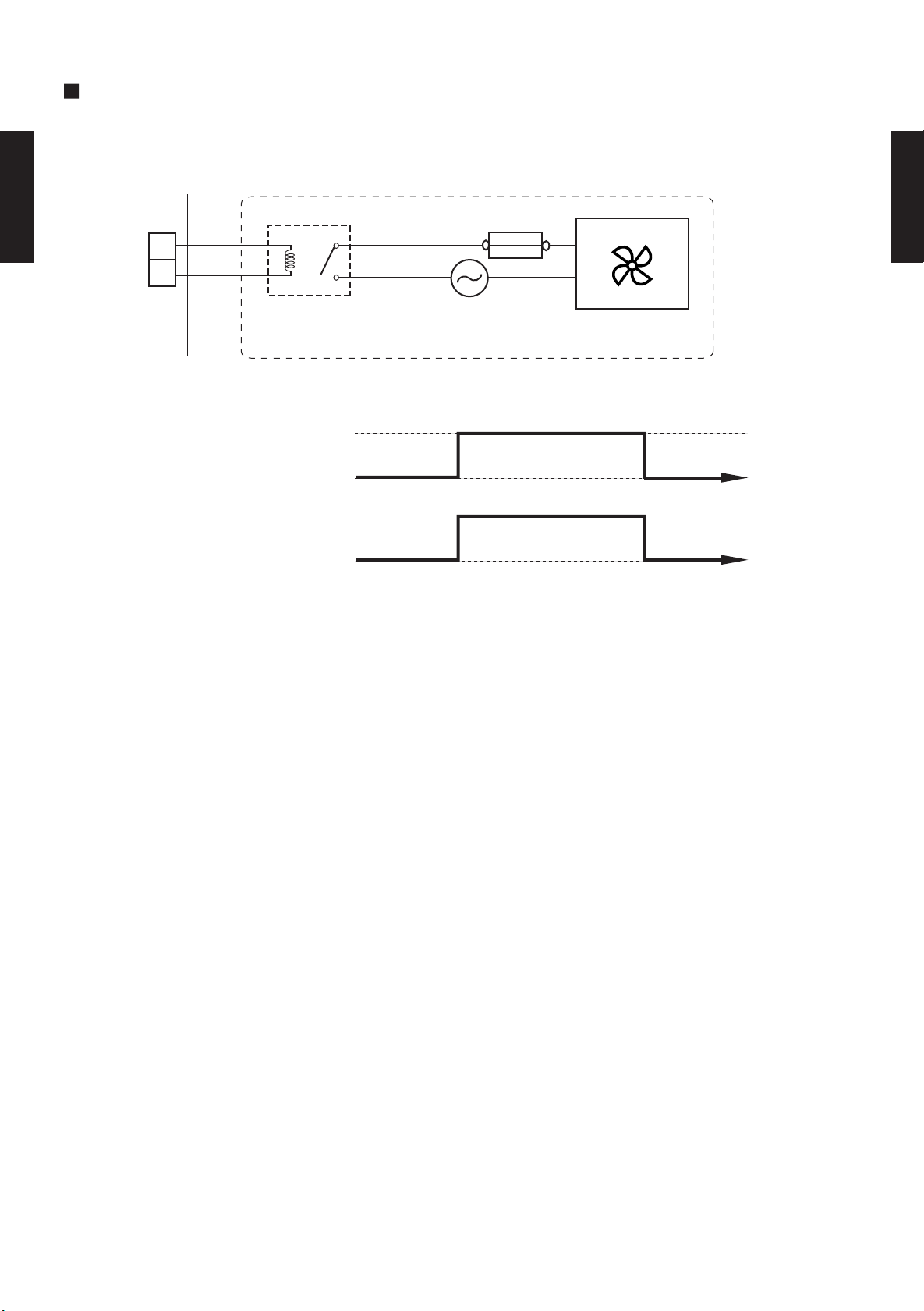
2-15. EXTERNAL INPUT & OUTPUT
FRESH
AIR OUTPUT SETTING
You can control sub fan by synchronizaton with fan operation of indoor unit.
[Example]
+
DUCT TYPE
AR7 - AR18K
Indoor
unit
1
2
Fuse
DUCT TYPE
AR7 - AR18K
-
CN11
(RED)
Indoor
unit fan
CN11
(Output)
Field supplied
Operation
Stop
14V
0V
Power
Fan, other
- (02 - 53) -
Page 55
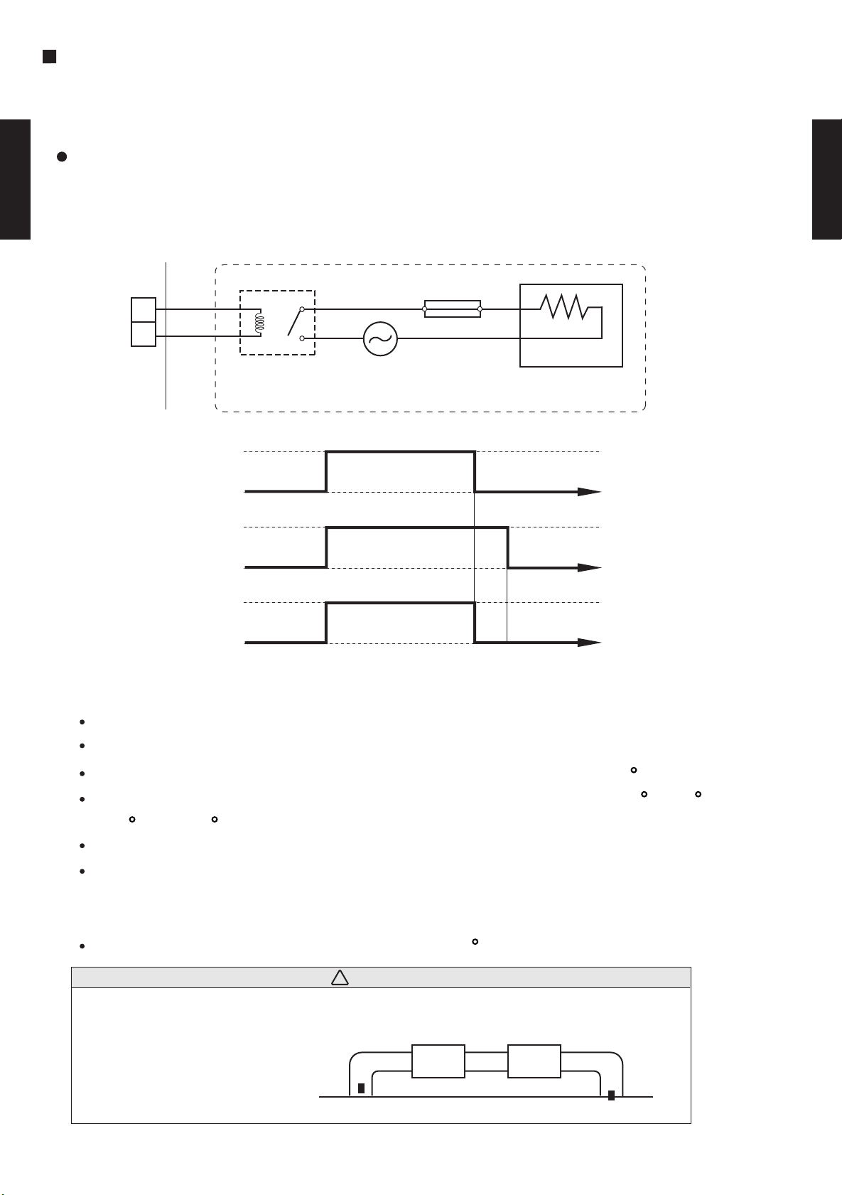
EXTERNAL
ELECTRICAL HEA
TER OUTPUT SETTING
You can control Electrical heater (Booster) by sychronization with heating operation.
When temperature is -10 to -3 degrees from Setpoint,External electrical heater is ON.
When temperature is -1 degrees from Setpoint,External electrical heater Stops.
Jumper wire (Indoor Unit)
This is used to continue indoor unit fan operation for 1 minute after thermo OFF in heating mode.
1 minute delay control set by turning switch 4-3 on PCB.
DUCT TYPE
AR7 - AR18K
[Example]
DUCT TYPE
AR7 - AR18K
+
Indoor
unit
1
2
-
CN10
(GREEN)
Indoor
Operation
unit
Heating
Indoor
Stop
Operation
unit fan
Stop
14V
CN10
(Output)
0V
<Operation condition>
All conditions shall be met.
Under heating operation.
Fan mode : Either Hi, Med, Low, Quiet.
Field supplied
Fuse
Power
External Heater, other.
1min
Cold air prevention function not working (Heat exchanger temperature over 27 C ).
Temperature subtracted set temperature from room temperature is between -10 C to -3 C.
-10 C < *T < -3 C *T=Room temperature
Compressor 3 minutes stop mode is released.
Defrosting mode is released.
<Release condition>
Do not meet above condition , or room temperature is 1 C below from set temperature.
CAUTION!
!
Please locate external a heater between the indoor unit and the ductwork.
Please be sure to use delay control of a fan.
External
Heater
Supply air
Indoor unit
Return air
- (02 - 54) -
Page 56
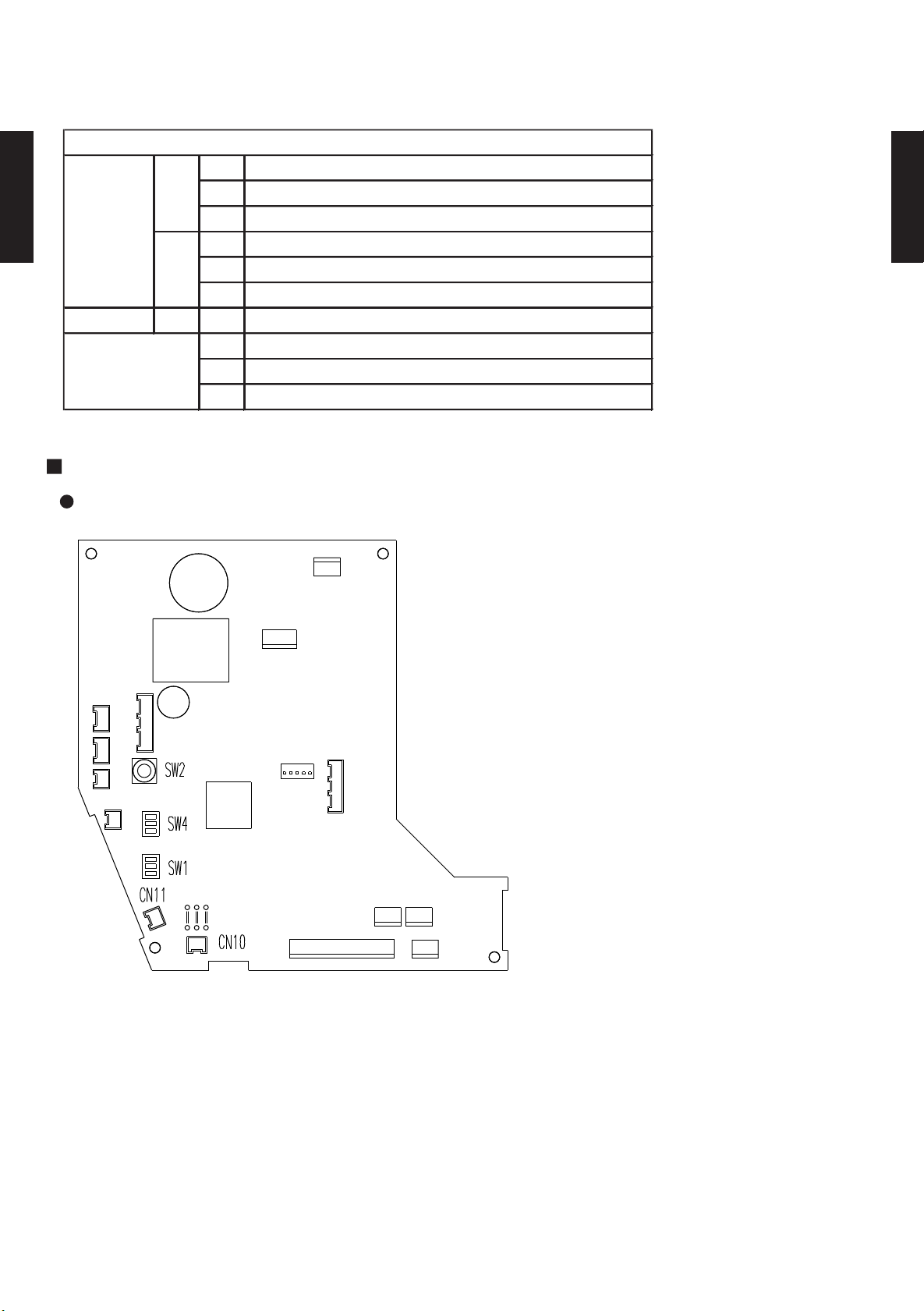
2-16. FUNCTION SETTING
Auto restart validity/invalidity
Room temperature correct coefficient of heating
Room temperature correct coefficient of heating
Forbidden
High(Low) static pressure function setting
Fan delay setting
Indoor unit number setting
Forbidden
Forbidden
Forbidden
INDOOR UNIT
DIP SW
Rotary SW
SW 2
3
1
JM3
SW 1
SW 4
Jumper Wire
23JM1
JM2
1
2
2-16-1. INDOOR UNIT
DUCT TYPE
AR7 - AR18K
SWITCH POSITION
DUCT TYPE
AR7 - AR18K
Indoor unit control circuit board
ON
OFF
3
2
1
ON OFF
3
2
1
JM1
JM2
JM3
- (02 - 55) -
Page 57

2-16-2. SWITCH FUNCTION (INDOOR UNIT)
the fan operation continues one minutes.
SW 4-3
SW state
OFF
Invalidity
Validity
ON
OFFON0 deg (Floor setting)
ONON+4 deg (Ceiling setting)
SW state
+2 deg
-2 deg
SW 1-3
OFF
OFF
ON
Low static pressure
SW 1-1
SW state
OFF
Invalidity
ON
Validity
SW 1-2
SW 4-1
SW 4-2
SW state
OFF
Normal
SW 4-2
OFFONSW state
Normal
High static pressure
OFF
ON
ON
DIP SWITCH SETTING
1-1.Auto restart setting
Auto restart function can be selected by turning this switch ON/OFF.
AUTO RESTART SETTING
DUCT TYPE
AR7 - AR18K
( Factory setting)
DUCT TYPE
AR7 - AR18K
◆
1-2.Room temperature correct coefficient of heating.
Decide the heating temperature correct coefficient vale of heating.
HEAT TEMPERATURE CORRECTION
( Factory setting)
◆
4-1.Dip SW 4-1setting forbidden
( Factory setting)
◆
4-2.High(Low) static pressure function setting
In case of installing in high(low) static, you can maximize(minimize) air flow and noise.
Model:AR*7 to 14
( Factory setting)
◆
Model:AR*18
( Factory setting)
◆
4-3.Fan delay setting
This setting can be used when the auxiliary heater is mounted.
When the fan operation is stopped when the indoor unit is operating with an auxiliary heater,
( Factory setting)
◆
- (02 - 56) -
Page 58

G
CN11-FRESH AIR
See external input/output
settings for details.
CN10
-
ELECTRICAL HEATER
Connector
INPUT
OUTPUT
REMARKS
JM state
JM 1, 2, 3
Connect
Disconnect
Forbidden
0
Single
1 - 15
Indoor unit address
SW 2
SW state
N
I
T
T
SE
H
C
T
WI
S
Y
R
A
OT
R
This switch can be used when group control system.
Set the indoor unit address in the 1,2,-,15 order.
( Factory setting)
◆
DUCT TYPE
AR7 - AR18K
JUM
1-1.JM 1, 2, 3 setting forbidden
E
◆
XT
P
E
E
R
R
N
A
W
L
I
R
NP
I
E
G
N
TTI
E
S
( Factory setting)
T
U
P
T
U
O
D
N
A
T
U
( Factory setting)
DUCT TYPE
AR7 - AR18K
- (02 - 57) -
Page 59

2-16-3. WIRED, SIMPLE REMOTE CONTROLLER CIRCUIT BOARD
Wired,Simple remote controller
1
Dual remote controller setting
2
Group control setting
DIP SW
DUCT TYPE
AR7 - AR18K
SWITCH POSITION
Wired remote controller
Front case (back side)
3
4
Model setting
Auto changeover setting
5
6
Memory backup setting
DUCT TYPE
AR7 - AR18K
DIP Switch
Simple remote controller
ON
OFF
12345
OFF
ON
1
2
3
4
5
6
ON
ON
6
DIP switches
- (02 - 58) -
Page 60

2-16-4. WIRED, SIMPLE REMOTE CONTROLLER
DIP SWITCH SETTING
1. SW setting
1-1 Dual remote controller setting
Set the remote controller DIP switch No.1 and 2 according to the following table.
( Factory setting)
DUCT TYPE
AR7 - AR18K
Number of
remote
controller
1 (Normal)
2 (Dual)
1-2 Group control setting
Number of indoor unit connection (One/Multiple)
This is switched according to the number of connected indoor units.
DIP-SW
No.3
OFF
Master unit Slave unit
DIP-SW
No.1
DIP-SW
No.2
ON
OFF
( Factory setting)
Number of indoor unit
One unit connection
OFF
OFF
DIP-SW
No.1
ON ON
DIP-SW
No.2
DUCT TYPE
AR7 - AR18K
ON Multiple unit connection
1-3 Model setting
The system type of the outdoor unit can be selected by setting up DIP switch No.4 as follows.
( Factory setting)
DIP-SW
No.4
OFF
ON Cooling only model
Heat Pump model
Model
1-4 Auto changeover setting
Selecting auto changeover validity / invalidity.
( Factory setting)
DIP-SW
No.5
OFF
ON Validity
Auto changeover
Invalidity
1-5 Memory backup setting
Set to ON to use batteries for the memory backup.if batteries are not used,
all of the settings stored in memory will be deleted if there is a power failure.
This function is wired remotecontroll only.
( Factory setting)
DIP-SW
No.6
OFF
ON Validity
Memory backup
Invalidity
- (02 - 59) -
Page 61

2-17. OPTIONAL PARTS
Simple remote controllers
UTB - YPB : FUJITSU BRAND
UTB - GPB : GENERAL BRAND
Remote controller which gives priority to ease-of-use and allows operation
of the necessary functions only.
DUCT TYPE
AR7 - AR18K
Remote sensor unit
UTD - RS100
Accurate and Comfortable
New amenity space can be offered by installing the thermo sensor in the remote controller.
Because the remote controller has the switching function, the user can select the position of the
sensor. (Room temperature sensor selection)
Example of room temperature
sensor selection
Sensor part
Simple remote
controllers
Remote Sensor
in the bed room (effective at night)
DUCT TYPE
AR7 - AR18K
Wired Remote Controller
THERMO
Day
The detecting point can be freely changed.
SENSOR
Night
Remote Controller
in the living room (effective during the day)
Remote Sensor (Optional Parts)
- (02 - 60) -
 Loading...