

Page 1
S P L IT TYPE
AIR C ONDITIONE R
C E IL ING
type
(50Hz)
Indoor unit Outdoor unit
ABHA30LBT
ABHA36LBT
AOHA30LBTL
AOHA36LBTL
CONTENTS
SPECIFICATIONS
DIMENSIONS
REFRIGERANT SYSTEM DIAGRAM
CIRCUIT DIAGRAM
ERROR CONTENTS
PARTS (INDOOR UNIT)
PARTS (OUTDOOR UNIT)
STANDARD ACCESSORIES
. . . . . . . . . . . . . . . . . . . . . .
. . . . . . . . . . . . . . . . . . . . . . . . .
. . . . . . . . . . . . . . . . . . . .
. . . . . . . . . . . . . . . . . .
. . . . . . . . . . . . . . .
. . . . . . . . . . . . .
. . . . . . . . . .
. . . . .
. . . . . . .
. . . . .
1
2
4
5
6INDOOR PCB CIRCUIT DIAGRAM
10OUTDOOR PCB CIRCUIT DIAGRAM
15
18
23
27
Page 2
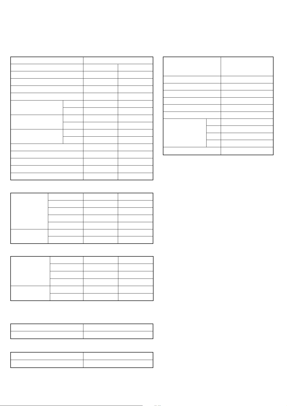
SPECIFICATIONS
ELECTRICAL DATA
TYPE
INDOOR UNIT ABHA30LBT
OUTDOOR UNIT
COOLING CAPACITY
HEATING CAPACITY
POWER SOURCE
RUNNING CURRENT
INPUT WATTS
E.E.R.
STARTING CURRENT
MOISTURE REMOVAL
AIRCIRCULATION INDOOR
AIRCIRCULATION OUTDOOR
MAXIMUM CURRENT
Cooling
Heating
Cooling
Heating
Cooling
Heating
Cooling & Heating
AOHA30LBTL AOHA36LBTL
8.5 kW 9.4 kW
10.0 kW
230 V 50 Hz 230 V 50 Hz
11.6 A
12.1 A
2.65 kW
2.77 kW
3.21 kW/kW
3.61 kW/kW
15 A
2.5 L/hr
3,600 m3/hr
17.0 A
FAN SPEED
INDOOR UNIT
OUTDOOR
UNIT
Discrimination
High speed
Med speed
Low speed
Quiet 650 r.p.m. 650 r.p.m.
Discrimination
Speed
MFH-45RV
1,000 r.p.m.
910 r.p.m.
750 r.p.m.
MFE-36TV
850 r.p.m.
ABHA36LBT
11.2 kW
12.8 A
13.2 A
2.93 kW
3.02 kW
3.21 kW/kW
3.71 kW/kW
15 A
3.0 L/hr
1,900 m3/hr1,660 m3/hr
4,000 m3/hr
20.0 A
MFH-45RV
1,100 r.p.m.
910 r.p.m.
750 r.p.m.
MFE-36TV
950 r.p.m.
COMPRESSOR AND REFRIGERANT
Hermetic type, Inverter,
COMPRESSOR TYPE
DISCRIMINATION
WEIGHT (with oil)
STANDARD REFRIGERANT
REFRIGERANT TYPE
MAX PIPE LENGTH
MAX PIPE HEIGHT
Pipe length
FULL CHARGE
ADDITIONAL CHARGE
20 m
30 m
40 m 2,900 g
50 m
4 poles, 3 phase,
DC motor, Twin Rotary
5KD240XAD21
16.3 kg
2,100 g
R410A
50 m
30 m
2,100 g
2,500 g
3,300 g
40 g/m
NOISE LEVEL
High speed 45 dB
INDOOR UNIT
OUTDOOR
UNIT
Note : Static pressure : 30Pa
Duct length : Inlet 1m, Outlet 2m
Med speed 43 dB
Low speed
Quiet
Cooling
Heating
DIMENSIONS
INDOOR UNIT H x W x D
H x W x DOUTDOOR UNIT
WEIGHT
INDOOR UNIT
OUTDOOR UNIT
Gross / Net
Gross / Net
47 dB
43 dB
37 dB
32 dB 32 dB
53 dB 54 dB
55 dB 55 dB
240 x 1,660 x 700 mm
830 x 900 x 330 mm
58 kg / 46 kg
70 kg / 62 kg
37 dB
2008.01.30 1
Page 3
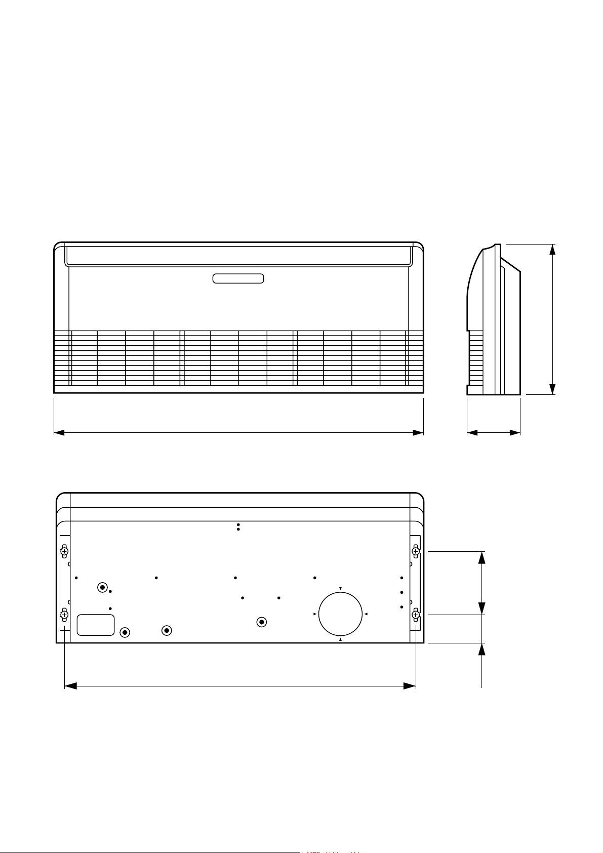
DIMENSIONS
INDOOR UNIT
(Unit : mm)
700
1,660 240
2008.01.30
1,600
130 300
2
Page 4
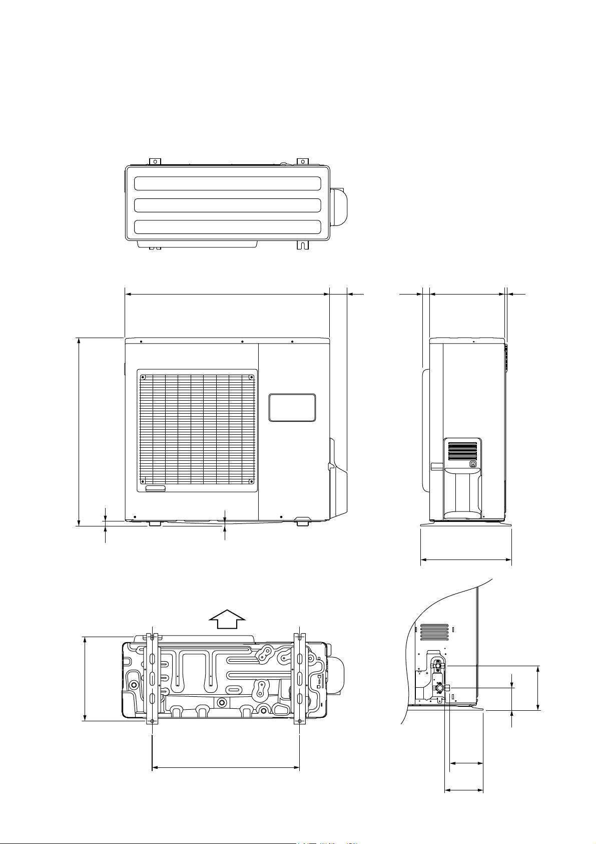
OUTDOOR UNIT
(Unit : mm)
77900
830
21
9
33031 12
400
2008.01.30
Air Flow
370
650
3
147
170
196
99
Page 5
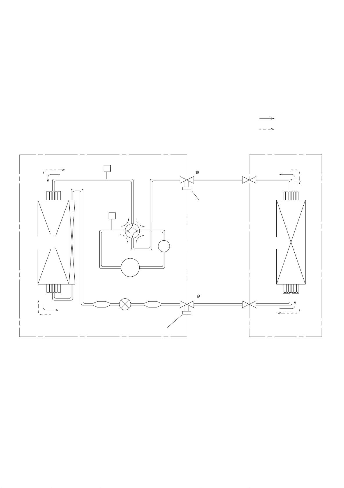
REFRIGERANT SYSTEM DIAGRAM
Refrigerant direction
: Cool
: Heat
OUTDOOR UNIT
Condenser
High
Pressure
Switch
Strainer
Pressure
Check Valve
4-way
Valve
Compressor
Expansion
Valve
Strainer
Refrigerant Pipe
15.88mm (5/8")
Charging
Valve
Accumulator
Refrigerant Pipe
INDOOR UNIT
Evaporator
9.52mm (3/8")
Charging Valve
2008.01.28 4
Page 6
STEP
MOTOR
STEP
MOTOR
FAN MOTOR
F M
GREEN /
YELLOW
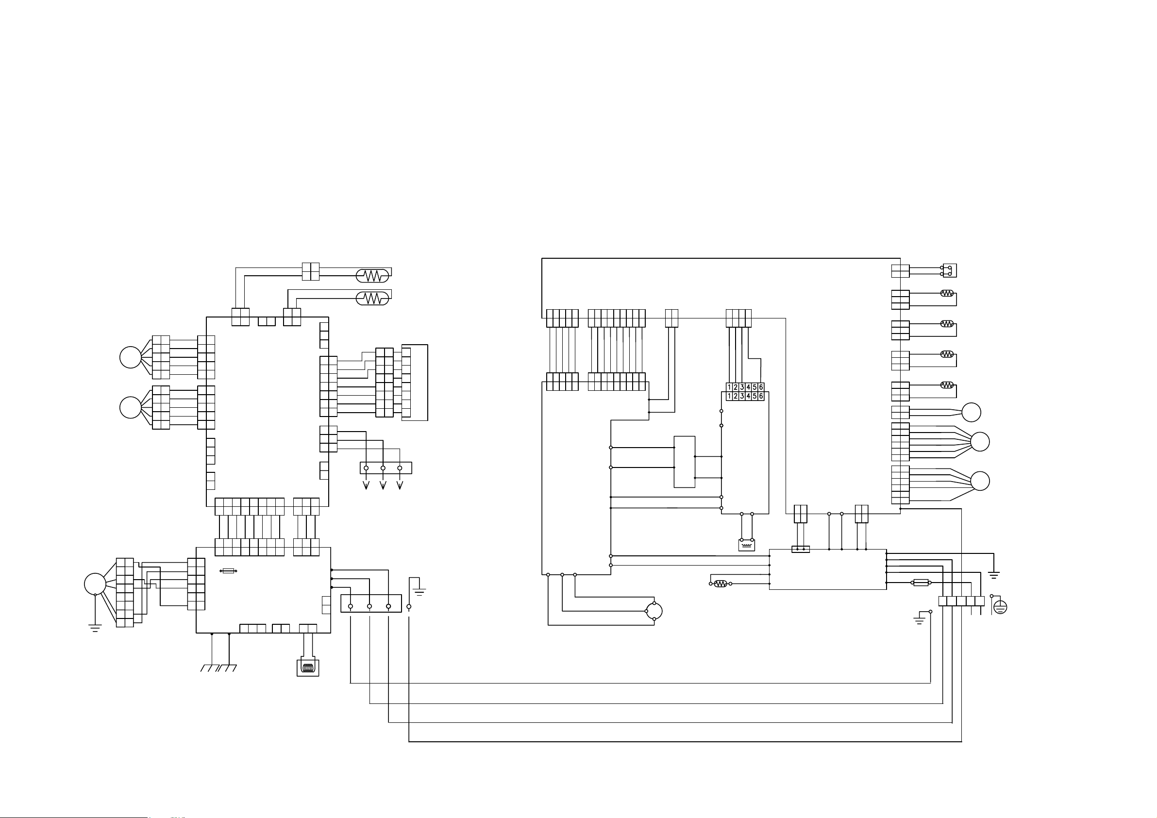
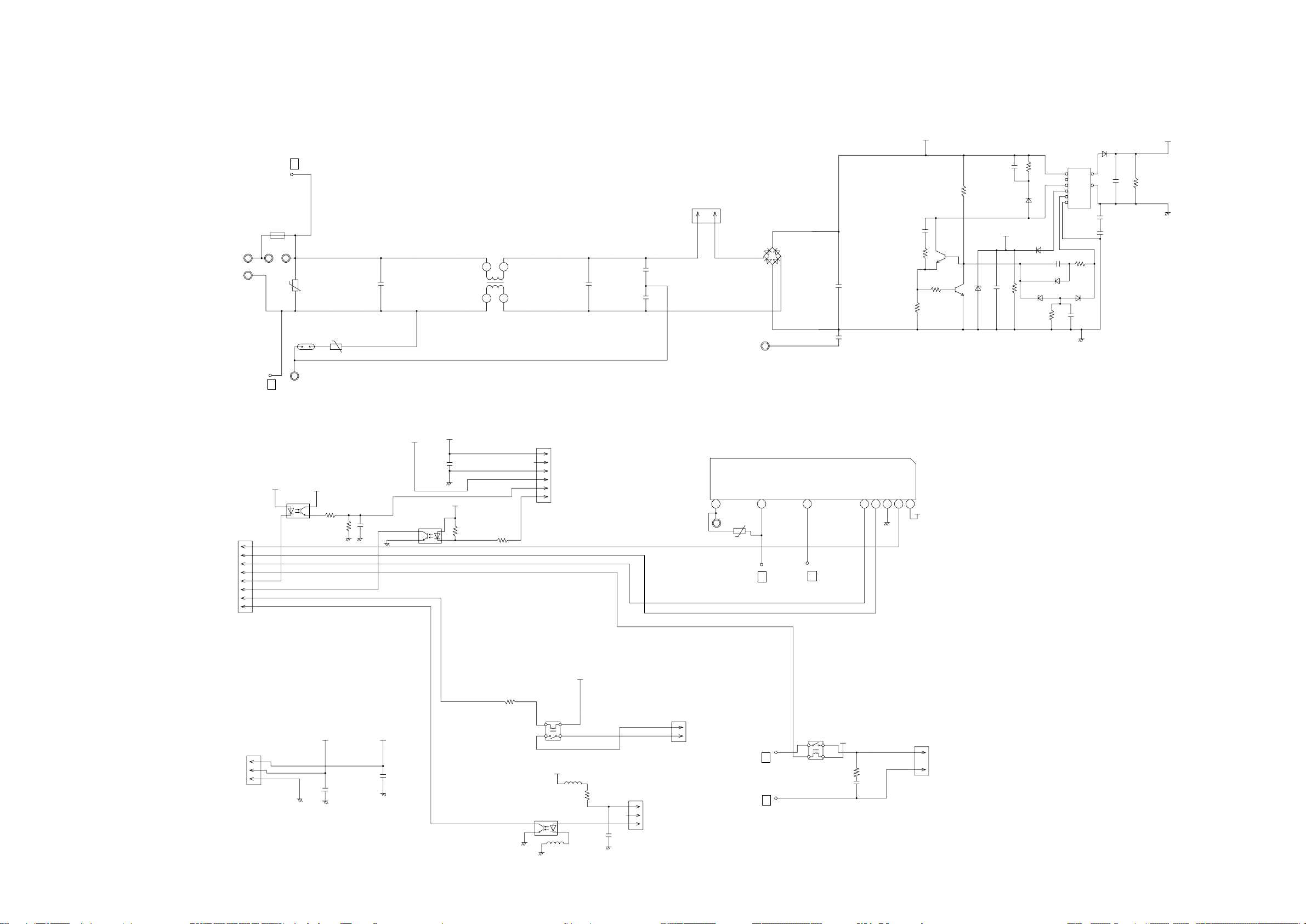
CIRCUIT DIAGRAM
INDOOR UNIT OUTDOOR UNIT
BLACK
BLACK
2 1
1
1
2
1
BROWN
1
1
2
2
3
4
5
1
2
3
4
5
YELLOW
3
4
5
1
2
3
4
5
BROWN
WHITE
BLACK
M
M
1
1
2
2
3
3
4
4
5
5
6
6
7
7
8
8
RED
ORANGE
YELLOW
WHITE
BROWN
RED
ORANGE
YELLOW
WHITE
RED
1
2
3
4
5
1
2
3
4
5
1
1
2
2
3
3
4
4
5
5
6
6
E101 E102
CN5 CN7
1
2
3
CN12
4
5
CONTROLLER
1
2
3
4
5
1
2
3
1
2
CN11
CN9
CN10
2 3 4 5 6 7
1
3 456
2
1
GRAY
GRAY
GRAY
3 456
2
1
2 3 4 5 6 7
1
F101
CN105
FUSE
( MAIN PCB )
CN4 CN1
CN104
3.15A 250V
CN102
1
PCB ASSY
GRAY
GRAY
GRAY
POWER
SUPPLY
PCB ASSY
3
2
2 1 2
CN8
8
7 8
GRAY
GRAY
7 8
8
CN103
2
1
2
1
1
1
1
CN101
1
2
2
2
GRAY
GRAY
2 3
2 3
W105
W102
W101
CN108
2
1
GRAY
1
GRAY
2
BLACK
BLACK
THERMISTOR
( PIPE TEMP. )
THERMISTOR
( ROOM TEMP. )
1
2
CN3
3
BROWN
1
1
RED
2
2
ORANGE
3
3
WHITE
4
4
BLUE
5
5
PURPLE
6
6
GRAY
7
7
RED
1
1
WHITE
2
2
BLACK
3
3
1
2
CN6 CN14 CN13
TO REMOTE CONTROL UNIT
3
3
GRAY
RED
WHITE
BLACK
1
2
CN106
1
1
2
2
3
3
4
4
5
5
6
6
7
7
8
8
2
1
( OPTION PART )
TERMINAL
1 2
3
1
2
3
4
5
6
7
8
TERMINAL
3
2 3 4 5
1
2 3 4 5
1
RED
BROWN
2 3 4 5
1
2 3 4 5
1
CN303
ORANGE
GREEN
YELLOW
2 3 4 5 6 7 8 9
1
2 3 4 5 6 7 8 9
1
RED
BROWN
2 3 4 5 6 7 8 9
1
2 3 4 5 6 7 8 9
1
INDICATOR PCB ASSY
TM302
TM301
TRANSISTOR
PCB ASSY
TM305
U
W17
W16
TM102
TM101
( I P M )
TM303
W
TM304
V
BLUE
GREEN
PURPLE
YELLOW
ORANGE
CN301
W306
W307
BLUE
YELLOW
COMPRESSOR
RED
WHITE
BLACK
GRAY
BLACK
CM
R
2
1
2
1
WHITE
BLACK
CAPACITOR
PCB ASSY
W8
PURPLE
W13
W7
W12
BLACK
RED
CHOKE COIL
BROWN
ORANGE
S
C
CN400CN200CN40CN42
2 3 4
1
2 3 4
1
BROWN
L0
N2
ACTPM
N1
WHITE
P
-
+
POSISTOR
RED
YELLOW
ORANGE
CN11
L2
L1
WHITE
ORANGE
ORANGE
HIGH PRESSURE SWITCH
RED
2
W4
121
3
2
1
3
2
1
3
2
1
3
2
1
2
1
6
5
4
3
2
1
6
5
4
3
2
1
RED
THERMISTOR ( COMPRESSOR TEMP. )
BROWN
3
2
BROWN
1
THERMISTOR ( OUTDOOR TEMP. )
BLUE
3
2
BLUE
1
THERMISTOR ( PIPE TEMP. )
BLACK
3
2
BLACK
1
THERMISTOR ( DISCHARGE TEMP. )
BROWN
3
2
BROWN
1
BLACK
2
BLACK
1
WHITE
6
YELLOW
5
ORANGE
4
BLUE
3
BROWN
2
RED
1
BROWN
6
YELLOW
5
WHITE
4
BLACK
3
2
RED
1
RED
GREEN
WHITE
BLACK
WHITE
4WV 4-WAY VALVE
EXPANSION VALVE
PMV
F M FAN MOTOR
BLACKBLACK
TERMINAL
NL321
CN90
CN64
CN62
CONTROLLER
CN65
PCB ASSY
( MAIN PCB )
CN63
CN500
CN700
CN801
TM600
CN1
2
1
2
1
WHITE
WHITE
WHITE
1 2
W29
CN100
W28
POWER SUPPLY
W25
W26
PCB ASSY
W21 W9
TM601
GRAY
BLACK
CN110
1
1
WHITE
W19
W20
2
2
BLACK
W3
W18
W17
W2
W1
FUSE 250V 25A
POWER SOURCE
2008.01.30
WHITE
GREEN
GREEN
WHITE
COIL
5
Page 7
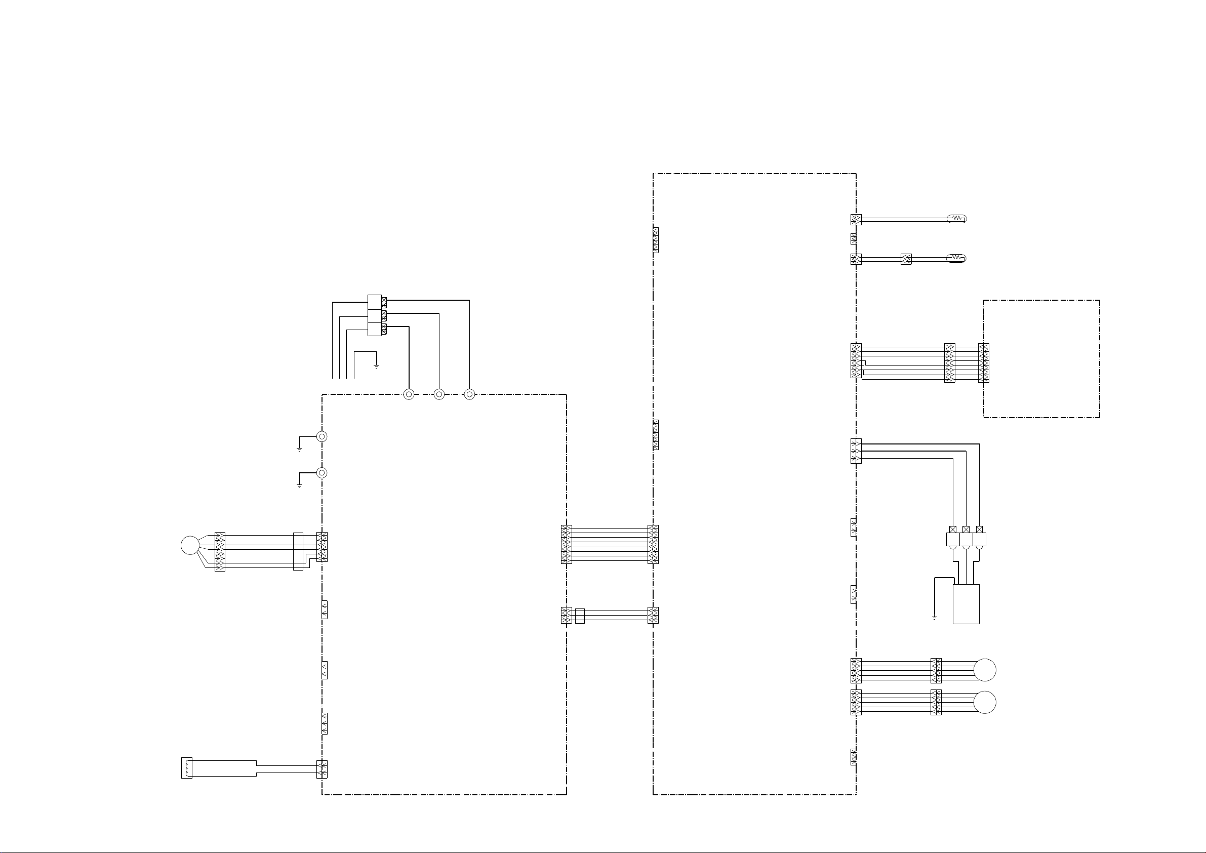
INDOOR PCB CIRCUIT DIAGRAM
INVERTER UNIT
ABHA30LBT : EZ-00712HSE
ABHA36LBT : EZ-00713HSE
TERMINAL BOARD
3
2(N)
1
OUTDOOR UNIT
UL1015 AWG16
GREEN
UL1015 AWG16
GREEN
E101
E102
UL1015 AWG20 BLACK
W101
UL1015 AWG20 WHITE
W102
UL1015 AWG20 RED
W105
TEST
CN8
CN2-1
CN2-2
CN2-3
CN2-4
CN2-5
CN2
B5P-SHF-1AA
WHITE
B02B-XASK-1-A
B02B-XAYK-1-A
B02B-XAKK-1-A
WHITE
CN7
YELLOW
CN5
BLACK
CN8-1
CN8-2
CN7-1
CN7-2
CN5-1
CN5-2
CONTROLLER PCB ASSEMBLY
( MAIN PCB )
ABHA30LBT : K06AK-0708HSE-C1
ABHA36LBT : K06AK-0709HSE-C1
CN13-1
CN13-2
CN13-3
CN13
WHITE
CN14
BLACK
CN13-4
CN13-5
CN13-6
CN13-7
CN14-1
CN14-2
CN14-3
CN3-1
CN3-2
CN3-3
CN3-4
CN3-5
CN3-6
CN3
B06B-PASK-1
WHITE
B07B-PASK-1
B03B-XAKK-1-A
BLACK
BLACK
BLACK
BLACK
UL1430 AWG28 BROWN
UL1430 AWG28 RED
UL1430 AWG28 ORANGE
UL1430 AWG28 WHITE
UL1430 AWG28 BLUE
UL1430 AWG28 PURPLE
UL1430 AWG28 GRAY
ROOM TEMPERATURE THERMISTOR
PIPE TEMPERATURE THERMISTOR ( M I D )
GRAY
GRAY
INDICATOR PCB ASSEMBLY
K04GN-0700HSE-D0
1
1
BROWN
CN201-1
RED
2
2
3
3
ORANGE
4
4
YELLOW
5
5
6
6
7
7
8
8
WHITE
BLUE
PURPLE
GRAY
CN201-2
CN201-3
CN201-4
CN201-5
CN201-6
CN201-7
CN201-8
CN201
JC25-08HG
WHITE
DC FAN MOTOR
F M
NORMAL COIL
( REACTOR ASSY )
RLEY41-22
22mH - 2.2A
1
UL1015 AWG22 RED
2
3
UL1015 AWG22 BLACK
UL1015 AWG22 WHITE
4
5
6
UL1015 AWG22 YELLOW
7
UL1015 AWG22 BROWN
8
DRAIN PUMP
E I B OUT
UL1015 AWG20 WHITE
UL1015 AWG20 WHITE
EMI FILTER
ATFC-25-15-12
2 TURN
E I B I N
POWER SUPPLY PCB ASSEMBLY
K06AL-0606HSE-P0
CN105-6
CN105-5
CN105
CN105-4
CN105-3
CN105-2
CN105-1
CN106-1
CN106-2
CN103-1
CN103-2
CN102-1
CN102-2
CN102-3
CN108-1
CN108-2
B5P6-VH-B
WHITE
CN106
B2P3-VH-B-E
BLUE
CN103
B2B-XH-AM
WHITE
CN102
B3B-XH-AM
WHITE
CN108
B2P3-VH-B
WHITE
B08B-PASK-1
B03B-PASK-1
CN104
WHITE
CN101
WHITE
CN104-1
CN104-2
CN104-3
CN104-4
CN104-5
CN104-6
CN104-7
CN104-8
CN101-1
CN101-2
CN101-3
POWER DRIVE
UL1430 AWG26 GRAY
UL1430 AWG26 GRAY
UL1430 AWG26 GRAY
UL1430 AWG26 GRAY
UL1430 AWG26 GRAY
UL1430 AWG26 GRAY
UL1430 AWG26 GRAY
UL1430 AWG26 GRAY
DC SUPPLY
UL1430 AWG26 GRAY
UL1430 AWG26 GRAY
UL1430 AWG26 GRAY
EMI FILTER
ZCAT1518-0730
2 TURN
CN4-1
CN4-2
CN4-3
CN4-4
CN4-5
CN4-6
CN4-7
CN4-8
CN1-1
CN1-2
CN1-3
CN4
B08B-PASK-1
WHITE
CN1
B03B-PASK-1
WHITE
CN6
B02B-PAMK-1
GREEN
CN10
B02B-PAOK-1
ORANGE
CN11
B05B-XASK-1-A
WHITE
CN12
B05B-XARK-1-A
B03B-XARK-1-A
RED
CN9
UL1430 AWG22 BLACK
UL1430 AWG22 WHITE
CN6-1
CN6-2
CN10-1
CN10-2
CN11-1
CN11-2
CN11-3
CN11-4
CN11-5
CN12-1
CN12-2
CN12-3
CN12-4
CN12-5
CN9-1
CN9-2
CN9-3
RED
FRESH AIR
UL1430 AWG28 BROWN
UL1430 AWG28 RED
UL1430 AWG28 ORANGE
UL1430 AWG28 YELLOW
UL1430 AWG28 WHITE
UL1430 AWG28 BROWN
UL1430 AWG28 RED
UL1430 AWG28 ORANGE
UL1430 AWG28 YELLOW
UL1430 AWG28 WHITE
FLOAT SWITCH
EARTH WIRE
REMOTE CONTROL UNIT
( OPTION PARTS )
BROWN
RED
ORANGE
YELLOW
WHITE
BROWN
RED
ORANGE
YELLOW
WHITE
UL1430 AWG22 RED
TERMINAL BOARD
3
1
2
LOUVER
M
U - V
LOUVER
M
L - R
2008.01.28 6
Page 8
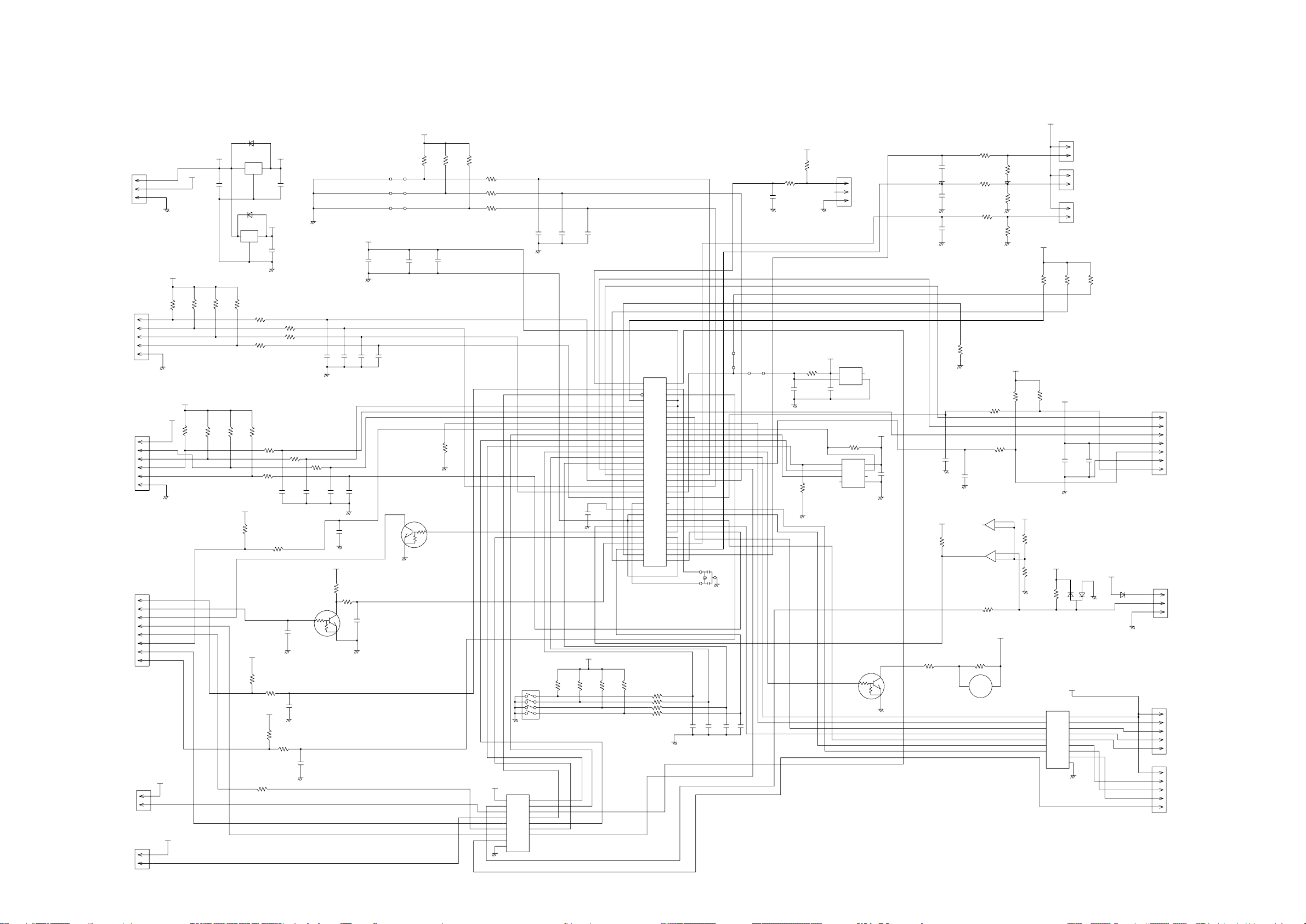
INDOOR UNIT
CONTROLLER PCB ASSEMBLY ( MAIN PCB )
ABHA30LBT : K06AK-0708HSE-C1
ABHA36LBT : K06AK-0709HSE-C1
CN1
B03B-PASK-1
DC SUPLLY
CN2
B5P-SHF-1AA
TEST
CN3
B06B-PASK-1
SP PCB
CN4
B08B-PASK-1
POWER DRIVE
CN6
B02B-PAMK-1
FRESH AIR
CN10
B02B-PAOK-1
HEATER
1
2
3
1
2
3
4
5
1
2
3
4
5
6
1
2
3
4
5
6
7
8
13.5V
1
2
1
2
5V
13.5V
13.5V
13.5V
5V
C1
10/
50V
R15 - R18
10K <1/10W> x 4
5V
10K <1/10W> x 3
R24
R23
<1/10W>
+
<1/10W>
R26
10K
R32
1SS355
NJM7812
1 3
1SS355
NJM7805
1
I
R67 1.0K
<1/10W>
5V
R30
10K
<1/10W>
D4
I C8
O
I
G
2
D1
I C2
5V
3
O
G
2
R19
R22
1.0K <1/10W> x 4
R66
C35 C12 C11
R25
1.0K
<1/10W>
5V
R31
10K
<1/10W>
5V
R33
10K
<1/10W>
R27
330
<1/10W>
12V
C2
+
10/
50 V
C3
0.01
<F>
R20
R21
1.0K <1/10W> X 3R63
1000P <R> x 3
C15
0.01
<F>
C17
0.01
<F>
R34
1.0K
CUSTOM CODE
CUSTOM CODE
HEATING FAN DELAY
R64
R65
R28
10K
<1/10W>
1
Q1
DTC124EKA
C18
0.01
<B>
5V
<1/10W>
3
2
C14
1000P
<R>
R29
390
C37
0.1
<F>
C16
0.01
<F>
5V
+
C32
100/
6.3V
C4 - C7
0.01 <F> x 4
JM1
JM2
JM3
C33
0.1
<F>
<1/10W>
Q3
DTC124EKA
3
2
5V
R1 - R3
10K <1/10W> x 3
C28
0.1
<F>
R70
10K
1
R4 - R6
1.0K <1/10W> x 3
SW1
CFS-0402MC
8
7
6
5
I C3
13.5V
uPA2003ADR
9
SK
I 1
16
O1
I 2
O2
15
I 3
14
O3
I 4
13
I 5
O4
12
O5
I 6
I 7
11
O6
10
O7
8
GND
1
2
3
4
5
6
7
C8 - C10
0.1 <F> x 3
4
3
2
1
C36
0.47
<F>
5V
I C1
uPD78F0535
34
AVREF
39
I C
RST
36
43
P00
44
P01
P02
45
46
P03
33
P10
32
P11
31
P12
30
P13
29
P14
28
P15
27
P16
26
P17
18
P20
19
P21
20
P22
21
P23
22
P24
P25
23
P30
11
12
P31
13
P32
14
P33
38
XT1
37
XT2
41
X1
X2
40
AGND
25
9
GND0
42
GND1
R11 - R14
10K <1/10W> x 4
R7 - R10
1.0K <1/10W> x 4
AVDD
VDD0
VDD1
35
10
24
15
P34
16
P35
P36
17
57
P40
58
P41
59
P42
P43
60
P44
61
62
P45
63
P46
64
P47
P50
1
2
P51
3
P52
4
P53
5
P54
6
P55
P56
7
8
P57
53
P64
54
P65
55
P66
56
P67
47
P70
48
P71
49
P72
P73
50
51
P74
52
P75
2008.01.28 7
3
2
1
X1
FCR5.0MC5T
5.00MHz
C19 - C22
0.1 <F> x 4
JM5
0R0
JM6
0R0
C31
0.01
<F>
R45
10K
<1/10W>
R46
1.0K
<1/10W>
C27
0.1
<F>
R37
10K
<1/10W>
5V
R56
100K
<1/10W>
0.1 <F>
C38
1
2
3
5V
FLOAT SWITCH
CN9
B03B-XARK-1-A
I C7
S80842
2
3
NC
VDD
1
4
OUT GND
R40
10K
<1/10W>
8
1
CS
VCC
2
4
SK
DO
7
3
D I
NC
5
6
GND
NC
I C5
BR93L56RF
Q2
DTC124EKA
1
5V
ROOM TEMP. TH.
1
CN8
2
C25
50V
12V
R48
10K
1
2
3
4
5
6
7
10/
I C4
1
2
1
2
5V
+
13.5V
SK
O1
O2
O3
O4
O5
O6
O7
GND
DAN217U
1 2
3
9
16
15
14
13
12
11
10
8
B2B-XASK-1-A
PIPE TEMP. TH. ( ENT )
CN7
B2B-XAYK-1-A
PIPE TEMP. TH. ( MID )
CN5
B2B-XAKK-1-A
C26
0.01
<F>
D2
12V
D3
D1FS4A
INDICATOR
CN13
B07B-PASK-1
1
2
3
4
5
6
7
CN14
B03B-XAKK-1-A
REMOTE CONTROL UNIT
1
2
3
CN11
B05B-XASK-1-A
LOUVER ( UP / DOWN )
1
2
3
4
5
1
2
3
4
5
CN12
B05B-XARK-1-A
LOUVER ( RHIGT / LEFT )
C29
0.1
<F>
C30
0.1
<F>
C34
0.1
<F>
NC
1.0K
<1/10W>
R58
1.0K
<1/10W>
R62
1.0K
<1/10W>
R52
10K
<1/10W>
R41 1.0K
<1/10W>
R57
<1/10W>
R43
10K
R59
10K
<1/10W>
R60
49.9K
<1/10W>
R61
49.9K
<1/10W>
5V
5V
R49 - R51
10K <1/10W> x 3
R44
10K
<1/10W>
5V
C23
C13
0.1
<F>
0.01
<F>
5V
R55
10K
<1/10W>
3
2
R36
0R0
PKM13EPYH-4000-A0
C24
1000P
<R>
7
BA10393F
1
BA10393F
R47
390
<1/10W>
R35
1.0K
<1/10W>
B Z
BZ1
R42
47
<1/10W>
6
-
5
+
I C6-2
2
-
3
+
I C6-1
13.5V
12V
R54
15.4K
<1/10W>
R53
28K
<1/10W>
<1/10W>
uLN2003ADR
1
2
3
4
5
6
7
I
I
I
I
I
I
I
Page 9
INDOOR UNIT
POWER SUPPLY PCB ASSEMBLY
K06AL-0606HSE-P0
L
I C26-14
F101
3.15A - 250V
<BET>
FH102
VA101
470V
<TNR>
PFC5000-0702F
x 2
SA101
RA-362M
VA102
470V
<TNR>
C101
0.22
<LE>
W101
BLACK
W102
WHITE
FH101
LF101
ELF20N018A
1
2
4
3
C104
0.22
<LE>
C105
0.01
<YE>
C106
0.01
<YE>
NORMAL COIL
2
1
CN108
B2P3-VH-B
E102
GREEN
<RS-2W>
C108
4700
D102
1SR139-600
15V
+
R110
10K
<1/10W>
R103
62K
2
3
5
6
7
8
D106
D1FL20U
C110 0.047 <ECQB>
D103
D1FL20U
D104
MTZJ5.1B
R109
330
<1/4W>
T101
ZFT22B03
D105
D1FL20U
C111
100/
+
25V
D108
D2FL20U
12
10
1000/
A
C113
25V
C114
0.01
<KH>
C115
0.01
<KH>
R108
100
<1/2W>
13.5V
R111
+
10K
<1/10W>
340V
<ECQM>
R104
330K
<2W>
C109
220P/
2.0kV
R105
1.5
75
Q101
2SC5354
2
3
2SC1815
R107
100
<1/10W>
1
Q102
1
2
3
D107
RD16M
<B1>
C112
330/
25V
D101
1
D3SB60
3
2
4
C107
+
270/
450V
<ECKE>
<RS-2W>
R106
<RS-2W>
C118
0.01
<KH>
POWER DRIVE
B08B-PASK-1
SERIAL I N
SERIAL I NT
SERIAL ON
DRAIN PUMP
DC FAN-OUT
DC FAN-FEEDBACK
EX. SIGNAL-OUT
EX. SIGNAL-I N
DC SUPPLY
I C26-10
CN104
CN101
B03B-PASK-1
E101
N
GREEN
CN105
B5P6-VH-B
6
5
4
3
2
1
G5NB-1A
4
2
I C101
TLP621
<GB>
4
3
BLm18
<AG601>
DC FAN MOTOR
K101
1
3
L102
BLm18
5V
<AG601>
1
2
L103
13.5V
R112
330
<1/10W>
C116
0.01
<B>
CN102
B3B-XH-AM
3
2
1
2
1
E I B I N
W105
CN103
B2B-XH-AM
8
RED
SERIAL
E I B OUT
VA103
470V
<TNR>
IC26-14
7
L
IC26-14
L
IC26-10
N
IC26-10
I C 105
H I 2002R
101418
6
N
K102
G5NB-1A
342
1
13.5V
5 4 3 2
3 2 1
5 4
RC101
120/
0.2
1
5V
CN106
B2P3-VH-B-E
2
1
DRAIN PUMP
C119
0.01
<KH>
I C103
TLP621
<GB>
4
3 2
340V
1
A
15V
R114
4.7K
<1/10W>
R115
6.8K
<1/4W>
R113
330
<1/10W>
15V
5V
1
2
3
4
5
6
7
8
1
2
3
1
2
I C104
TLP621
<GB>
15V
4
3
R116
1.0K
<1/4W>
R117
<1/4W>
5V
C121
0.1
<F>
820
+
C117
100/
25V
AA
13.5V
C120
0.1
<F>
2007.12.18 8
Page 10

INDOOR UNIT
INDICATOR PCB ASSEMBLY
K04GN-0700HSE-D0
5V
R201 - R203
330 <1/4W> x 3
D205 EMPG3863X <GREEN>
TO MAIN PCB
OPERATION
TIMER
LOUVER
LOUVER
5V
REMOTE SIGNAL
GND
MANUAL AUTO SWITCH
BROWN
RED
ORANGE
YELLOW
WHITE
BLUE
PURPLE
GRAY
CN201
08 / 08 JC / XMR
1430 L=300
D206 EMAA3863X <ORANGE>
1
2
3
4
5
6
7
8
SW201
EVQPAG04K
1
2
3
4
MANUAL AUTO SWITCH
D207 EBR3864X <RED>
C202
+
10/
16V
C201
0.1
<F>
PHA201
JM201
P I C-37143TH5
2
VCC
1
OUT
3
GND
2007.12.18 9
Page 11

POWER SOURCE
AC230V
50Hz
INDOOR UNIT
OUTDOOR PCB CIRCUIT DIAGRAM
INVERTER ASSEMBLY
AOHA30LBTL : EZ-007LHUE
EMI FILTER
ZCAT2132-1130
1 TURN
UL1015
AWG14
WHITE
N
UL1015
AWG14
BLACK
L
UL3271
AWG20
RED
3
UL1015
AWG20
WHITE
2
UL1015
AWG20
BLACK
1
TLC 25A - 250V, B
( 250V 25A )
EMI FILTER
ZCAT1518-0730
1 TURN
AOHA36LBTL : EZ-007MHUE
W1
UL1015
B
AWG14
BLACK
W2
B
POWER SUPPLY PCB ASSEMBLY
W17
B
K05CW-0702HUE-FL0
W28
W29
B
B
UL1015 AWG14 ORANGE
UL1015 AWG14 BLACK
EMI FILTER
ZCAT2132-1130
2 TURN
TM101
TM102
2
3
+
-
D100
D25XB60
1
4
DC FAN MOTOR F M
EXPANSION VALVE
4-WAY VALVE
F100
FSL 250 10 ( EM )
( 250 10A )
CT I N / OUT
W19
W20
B
B
UL3271 AWG20 BLACK
UL3271 AWG20 WHITE
2 1
CN110
3-1747052-4
YELLOW
VAC I N 1
W9
TM601
W21
B
B
UL3271 AWG14 GRAY
UL3271 AWG14 BLACK
TM600
POWER RELAY CONTROL
CONTROLLER PCB ASSEMBLY
CN100
2 1
UL1430 AWG24 WHITE
UL1430 AWG24 WHITE
2
CN1
1871843-2
WHITE
1
W25
B
UL3271
AWG20
ORANGE
ZPR0YCE400A300
W26
B
UL3271
AWG20
ORANGE
EMI FILTER
ZCAT2132-1130
2 TURN
CHOKE COIL
L=0.32MH 30A
UL3271
AWG14
WHITE
L1
ACTPM
I C 4 0 4
PM601BSG
6
543
L2
2
UL3271
AWG14
WHITE
P
N1
1
+
-
EMI FILTER
ZCAT1518-0730
1 TURN
CAPACITOR PCB ASSEMBLY
K05FB-0700HUE-P0
UL1015
AWG14
WHITE
UL1015
AWG14
VIOLET
W12
B
W13
B
UL1015 AWG14 RED
UL1015 AWG14 BLACK
W7
UL1015 AWG14
B
YELLOW
W8
UL1015 AWG14
B
BLUE
W16
B
W17
B
TRANSISTOR PCB ASSEMBLY
( I P M )
K07BT-0702HUE-TR0
TM301
TM302
I P M CONTROL
W306
B
W307
B
123
CN301
1971032-9
WHITE
4
567
9
8
TM305
TM304
TM303
REVERCE CURRENT
CN303
1971032-5
WHITE
123
4
5
ZCAT2132-1130
RED
WHITE
BLACK
UL3271
AEG14
x 3
EMI FILTER
1 TURN
C M
COMPRESSOR
W4
RED
B
UL3271
AWG16
GREEN
EARTH
SERIAL
W18
W3
B
B
( MAIN PCB )
AOHA30LBTL : K07BS-0704HUE-C1
AOHA36LBTL : K07BS-0705HUE-C1
RED
1
2
BLACK
WHITE
YELLOW
BROWN
RED
BROWN
BLUE
M
ORANGE
YELLOW
WHITE
BLACK
BLACK
CN801
3
4
B5P6-VH-B-L
5
WHITE
6
1
2
CN700
3
4
B6B-XARK-1-A
5
RED
6
CN500
1
1747052-1
2
WHITE
DC FAN MOTOR
EXPANSION VALVE
4-WAY VALVE
UL1007 AWG24 ORANGE
UL1007 AWG24 YELLOW
UL1007 AWG24 RED
432
CN400
1-1971032-4
RED
ACTPM CONTROL
UL1007 AWG24 BROWN
1
UL1015 AWG20 WHITE
UL1015 AWG20 BLACK
2
1
CN200
1-1747052-2
RED
VDC I N
EMI FILTER
ZCAT1518-0730
2 TURN
UL1007 AWG24 WHITE
UL1007 AWG24 WHITE
UL1007 AWG24 WHITE
987
1971032-9
I P M CONTROL
UL1007 AWG24 WHITE
6
CN40
UL1007 AWG24 WHITE
543
WHITE
UL1007 AWG24 WHITE
UL1007 AWG24 WHITE
UL1007 AWG24 WHITE
UL1007 AWG24 WHITE
1
2
UL1007 AWG24 WHITE
UL1007 AWG24 WHITE
UL1007 AWG24 WHITE
543
CN42
1971032-5
WHITE
UL1007 AWG24 WHITE
UL1007 AWG24 WHITE
1
2
REVERSE CURRENT
PRESSURE SWITCH
C90
1
2
1-1871843-2
RED
C64
1
2
2-1971032-3
3
BLUE
1
C62
2
1971032-3
3
WHITE
1
C63
2
3-1971032-3
3
YELLOW
1
C65
2
3
1-1971032-3
RED
PRESSURE SWITCH
THERMISTOR ( COMPRESSOR TEMP. )
THERMISTOR ( OUTDOOR TEMP. )
THERMISTOR ( DISCHARGE TEMP. )
THERMISTOR ( PIPE TEMP. )
BROWN
BROWN
BLUE
BLUE
BROWN
BROWN
BLACK
BLACK
RED
RED
2008.02.29 10
Page 12

OUTDOOR UNIT
CONTROLLER PCB ASSEMBLY ( MAIN PCB )
AOHA30LBTL : K07BS-0704HUE-C1
AOHA36LBTL : K07BS-0705HUE-C1
CN200
1-1747052-2
RED
R21
27K
<1/10W>
JM200
1
2
P-AN-CT
R24
1.0K
3
1
2
Q200
2SC2412K
<BQ>
12V
C5
0.1
<F>
SERIAL CIRCUIT
R23
27K
<1/10W>
12V
D1
SLR332VR
<RED>
R3
2.2K
<1/10W>
16
1C
1B
15
2C
2B
14
3C
3B
13
4C
4B
12
5C
5B
11
6C
6B
10
7C
7B
9 8
COM
I C2
uLN2003ADR
P-FANPWM
P-FAN-I N
P-EPV-D
P-EPV-C
P-EPV-A
P-EPV-B
P-PFC-C
P-AN-TE
P-AN-TD
P-AN-TA
P-AN-AC
TM601
TM600
CN110
3-1747052-4
YELLOW
AC VOLT I N
W4
RED
SERIAL
CN500
1747052-1
WHITE
4WV
CN1
1871843-2
WHITE
POWER RELAY CONTROL
CN801
B5P6-VH-B-L
DC FAN MOTOR
EXPANSION VALVE
CN90
1-1871843-2
RED
PRESSURE SWITCH
CN65
1-1971032-3
RED
THERMISTOR ( PIPE TEMP. )
CN63
3-1971032-3
THERMISTOR ( DISCHARGE TEMP. )
WHITE
THERMISTOR ( OUTDOOR TEMP. )
CN64
2-1971032-3
THERMISTOR ( COMPRESSOR TEMP. )
BLUE
CURRENT DETECTION CIRCUIT
CT600
CT-1B
4
5
PFC5000-0502 x 2
FH110
L
2
1
N
FSL 250 3.15 ( EM )
3
1
FH111
F110
SERIAL
B
1
2
CR500
RE1202
0.2/120
JM504
JM503
12V
1
2
C802
D801
0.1
HZ24BP
<F>
R801
+
22K
<1/10W>
1
2
CN700
3
B6B-XARK-1-A
4
RED
5
6
CN62
1971032-3
WHITE
12V
1
2
3
4
5
6
1
2
1
2
3
1
2
3
1
2
3
1
C60
2
0.1
<F>
3
DAN217U
R600 1.0K
15V
L800
R800
27K
<1/10W>
C800
4.7/
2 1
50V
3
D800
DAN217U
5V
R91
2.2K
<1/10W>
L90
BL02Rn1
5V
L60 BL02Rn1
D600
<1/10W>
1%
18
8
15V
1
3
5V
5V
R802
10K
<1/10W>
<1/10W>
DCFAN
C90
0.1
<F>
R63 4.75K
<1/10W>
R65 38.3K
<1/10W>
<1/10W>
16
12
13
<1/10W>
R601 1.0K
5V
<1/10W>
1
3
2
+
C600
220/25V
R602 4.75K
H Y I C 2 0
G K - 3 0 4 3 4 E 2
14 10
6
7
JM501
JM502
Q801
DTA143EUA
2
3
1
DTC143EUA
R803
1.0K
I C700
TD62064
3
O1
I 1
2
6
7
O2
I 2
11
9
O3
I 3
14
O4
I 4
GND1
COM1
GND2
COM2
GND3
GND4
R90
1.0K
<1/10W>
1
8
10
NC1
15
NC2
4
5
THERMISTOR
1%
<1/10W>
R61
13K
<1/10W>
1%
<1/10W>
R68
13K
<1/10W>
1%
<1/10W>
1%
5V
G5NB-1A
12V
2
Q800
C801
0.01
<B>
EE-VALVE
C91
0.1
<F>
R62
10K
R60
10K
R64
10K
R69
10K
<1/10W>
5 4 321
K500
1
3
12V
C700
DC VOLT I N
R603
22K
C601
0.1
<F>
5V
123
45
R22 1.0K
<1/10W>
2
4
R703, R702, R700, R701
1.5K <1/10W> x 4
0.1
<F>
PR-SW
C62
0.1
<F>
C61
0.1
<F>
C63
0.1
<F>
C65
0.1
<F>
<1/10W>
R20
10K
<1/10W>
C20 0.022 <F>
2007.12.25 11
PFC5000
-0502 x 2
C21
0.022
<F>
1
2
3
4
5
6
7
E
DC HIGH VOLTAGE
FH200 FH201
F201
FSL 250 3.15 ( EM )
P-S I
P-POWER
P-SO
P-PR
P-LED
P-V4-DC
P-V4-AC
P-DBG-4
P-FAN-I N
P-DBG-4
P-FANPWM
P-PFC-C
P-AN-CT
P-PFCPWM
TTXD
TAUX3
P-TTRIP-RE
P-POS
P-V4-AC
P-V4-DC
P-LED
P-PR
P-SO
P-TTRIP-FO
P-E2P-CS
P-EPV-B
P-EPV-D
P-EPV-C
P-AN-I L
P-AN-DC
P-AN-AC
P-AN-TE
P-AN-TA
P-AN-TD
+
C211
33/
450V
R900
10K
<1/10W>
JM100
5V
1SS355
UDZS8.2B
R12
0R0
1SS355
R13
<1/10W>
47/35V
C1
0.1
<F>
D2
D3
D4
47
C6
1
15V
+
3
8.00MHz
<CSTLS>
2
R14
560K
<1/8W>
1%
R15 - R17
510K
<1/8W>
1% x 3
C7
0.1
<F>
17
P62
16
P46
2
P12
35
3
P50
P37
59
58
P36
P40
60
21
MD2
34
P11
47
P26
27
P02
P03
28
29
P04
30
P05
P06
31
32
P07
33
P10
57
C
P20
41
42
P21
43
P22
P23
44
10
P57
9
P56
8
P55
7
P54
5
P52
6
P53
4
P51
22
X0
23
X1
X1
R18
150K
<2W>
UF4005
1
2
SMS
3
S
4
C
TOP243PN
I C1
MB90467
AGND
MICOM
I C3
VCC
AVCC
P00
P01
P17
P13
P14
P15
P16
AVR
P24
P25
P30
P31
P32
P33
P34
P35
P60
P61
MD0
MD1
P44
P43
P42
P41
P45
RSTX
P27
GND
GND
R19
0R0
D5
C8
2200P
<E>
S
D
56P63
11
25
26
40
36
37
38
39
12
45
46
50
51
52
53
54
55
14
15
18
20
64
63
62
61
19
48
13
24
49
1
2
3
4
5 6
8
7
5
0.1 <F> x 2
R6 1.0K
<1/10W>
1
RPZ-1F
C2, C3
U
X
V
Y
W
Z
C11
0.1
<F>
T1
5V
5V
D6
D1FL20U
C9
+
220/50V
10
9
8
7
C18
100/25V
D10
1SS355
-8V
5V
C4
+
5V
10/
25V
TEST
R2
10K
<1/10W>
JM2
5V
R7
10K
<1/10W>
R903, R902, R901
<1/10W> x 3
AOYA30LBTL type
JM10
R10 100K
R11
1.0K
<1/10W>
2
1
BU4842F-TR
C19
0.1
<F>
D7 - D9
D1FL20U x 3
+
+
C13
330/25V
+
C14
470/
25V
R26 10K
<1/10W>
15V
12V
C22
<F>
0.1
I C4
7805
SW POWER SUPPLY
R4
10K
<1/10W>
JM1
SERVICE
JUMPER 2
SW2
KSHG0611BT
JM102
MODEL SWITCH 1
JM103
MODEL SWITCH 2
JM101
MODEL SWITCH 0
5V
<1/10W>
NC
VDD
OUT
GND
C12
<F>
3
4
I C10
D12
1SS355
I C5
7818
123I O
G
+
D13
1SS355
O
1
I
G
+ +
2
C15
100/
25V
TAUX
P-E2P-SK
P-SPDPOW
P-POWER
P-E2P-D I
P-EPV-A
PPFCTRIP
P-U
P-X
P-V
P-Y
P-W
P-Z
P-PFCEN
TMODE
TCK
TRXD
TRES
0.1
P-S I
18V
C10
10/50V
3
C16
0.1
<F>
5V
C17
100/
25V
P-TTRIP-RE
P-TTRIP-FO
PPFCTRIP
P-SPDPOW
P-AN-I L
1000P
P-AN-DC
P-POS
P-U
P-V
P-W
P-X
P-Y
P-E2P-CS
P-E2P-SK
P-E2P-D I
P-PFCEN
UNDER VOLTAGE
OVER VOLTAGE
C49
1000P
<B>
JM50
C50
<B>
JM51
0R0
C42
1000P
<B>
C670
0.1
<F>
C74
100P
<CH>
P-Z
EEPROM
R31
10K
<1/10W>
C641
0.01
R49
1.0K
<1/10W>
R50
1.0K
<1/10W>
Q50
DTC114EUA
R41
1.0K
<1/10W>
R674
1.0K
<1/10W>
R85
27K
<1/10W>
VOLTAGE LOCK OUT CIRCUIT
5V
R645
10K
<1/10W>
<F>
R651
10K
<1/10W>
C644
0.01
<F>
5V
R51
10K
<1/10W>
3
1
R84
1.0K
<1/10W>
I C30
S-93C56BD0I
1
CS
2
SK
3
D I
TEST
7
NC
R30
10K
<1/10W>
5V
5V
1
3
<1/10W>
2 1
5V
8
VCC
4
DO
6
5
GND
<1/10W>
1
I C640-1
BA2903F
I C640-2
BA2903F
7
C645
0.1
<F>
D40
DAN217U
2
2
R40
10K
5V
D670
3
DAN217U
5V
C30
0.1
<F>
R401
22K
C401
1000P
15V
<B>
5V
2
-
3
+
6
-
5
+
5V
2
A
DTC143EUA
Q401
R644
1.0K
<1/10W>
C640
0.01
R650
<F>
1.0K
JM600
<1/10W>
0R0
C643
0.01
<F>
CN42
1971032-5
WHITE
5
4
3
3
1
I P M CONTROL
ACTPM CONTROL
2
3
1
R403, R402
A
<1/10W>
R640
150K
<1/3W>
1%
R641, R642
120K
<1/3W>
x 2
R646, R647
2.2K
<1/10W>
x 2
R648
4.75K
<1/10W>
1%
R649
0R0
PEAK LOAD CURRENT DETECTION
REVERSE CURRENT DETECTION
FO
DC VOLTAGE DETECTION
COMP POSITION DETECT
15V
C43
0.1
<F>
-8V
18V
D11
HZ24BP
1
Q400
3
DTA143EUA
270
18V
C400
0.01
<F>
A
1-1971032-4
1% x 2
A
CN40
1971032-9
WHITE
1
2
3
4
5
6
7
8
9
1
2
3
4
CN400
RED
+15V
-8V
UP
VP
I P M CONTROL
WP
UN
VN
WN
ACTPM CONTROL
Page 13

OUTDOOR UNIT
TRANSISTOR PCB ASSEMBLY
K07BT-0702HUE-TR0
TM101
ORANGE
TM102
BROWN
+15V
-8V
UP
VP
WP
UN
VN
WN
CN301
1971032-9
WHITE
9
8
7
6
5
4
3
2
1
C301
0.1
<F>
POWER-GND
15V
C308
+
47/
35V
IPM-G
-8V
P
N
C300
2
3
PEAK LOAD CURRENT DETECTION
REVERSE CURRENT DETECTION
W306
WHITE
B
TM301
TM302
W307
BLACK
B
DC VOLTAGE DETECTION CIRCUIT
I C70-8P
I C70-1
BA2903F
1
I C70-4P
0.1
<F>
DB CIRCUIT
1
+
4
-
D100
D25XB60
DC VOLTAGE DETECTION
COMP POSITION DETECT
POWER-GND
CN303
1971032-5
WHITE
FO
COMP POSITION DETECTION
+
-
C70
25V
15V
3
2
+
IPM-GND
C71
10/
0.1
<F>
C72
470P
<B>
C73
330P
<B>
DAN217U x 2
212 1
C161
<X7R>
1
2
3
4
5
D70, D71
3 3
R80
5.6K
<1/10W>
1%
R108
4.3K
<1/10W>
1%
0.1
L70
R81
33K
<1/10W>
1%
R107
39K
<1/10W>
1%
IPM-GND
W16
RED
B
W17
BLACK
B
R71
150K
<1/3W>
1%
R70
120K
<1/3W>
1%
R69
120K
<1/3W>
1%
PEAK LOAD CURRENT DETECTION CIRCUIT
C44
100P
<CH>
R44 30K
10K <1/10W>
R54
5
+
6
C51
0.01
<B>
<1/10W>
BA4560RF
1% x 2
1%
-
1
+
I C40-1
R46 30K
<1/10W>
1%
R53
R55 8.2K
<1/10W>
1%
R42, R43
15V
A-GND
R52 10K
<1/10W>
IPM-GND
4.7K <1/10W> 1% x 2
6
I C40-2
-
7
5
+
BA4560RF
1%
C50
470P
<B>
A-GND
I C40
8P
I C40
4P
15V
-8V
C47
0.1
<F>
C48
0.1
<F>
2
3
C46
0.15
<ECQB>
R48
22K
<1/10W>
IPM-GND
<1/10W>
R45
1.0K
D41
<1/10W>
RB751V
<1/10W>
I C70-2
BA2903F
R57
47K
7
1%
1%
C45
1000P
<B>
15V
R56
10K
REVERSE CURRENT DETECTION CIRCUIT
A-GND
150K <1/3W>
1% x 3
R66
R63
R60
R284, R285, R302
0.035 <5W> x 3
R304
820
<1/10W>
C328
2200P
<B>
TM305
RED
TM304
WHITE
TM303
BLACK
POWER-GND
15V
C332
C302
VNC
C I N
CFO
L300
47/
BL02Rn1
35V
D307
+
HZ24BP
28
VN1
27
26
25
FO
24
UN
21
22
VN
23
WN
P
37
36
U
V
35
W
34
NU
33
32
NV
31
NW
C327
0.022
<F>
C330
100P
<CH>
IPM-GND
120K <1/3W>
1% x 6
R68
R65
R62
CURRENT DETECTION CIRCUIT
R67
R64
R61
0.1
<F>
R360
D301 - D303
68
US1J x 3
<1/4W>
R76 5.76K
<1/10W> 1%
R77 143
<1/10W> 1%
C323
0.22
<F>
C322
0.22
<F>
C321
0.22
<F>
R316
R317
R318
R319
R320
R321
470 <1/10W>
x 6
IPM-GND
+
C305
47/35V
+
C304
47/35V
+
C303
47/35V
C311 - C316
1000P <B> x 6
C324 - C326
0.1 <F> x 3
IPM-G
6
UP
4
VP1
3
VUFB
1
VUFS
12
VP
VP1
10
9
VVFB
7
VVFS
18
WP
16
VP1
20
VNO
15
VWFB
13
VWFS
38
NC
I C301
PS21767
INVERTER
2007.12.28 12
Page 14

OUTDOOR UNIT
POWER SUPPLY PCB ASSEMBLY
K05CW-0702HUE-FL0
CT OUT
W9
BLACK
W21
GRAY
W25
ORANGE
B
PTC OUT
W26
B
ORANGE
B
L
N
L
TO INDOOR UNIT
N
AC VOLT OUT
EARTH
W1
BLACK
B
W2
WHITE
B
FH100
PFC5000
- 0502
FH101
PFC5000
- 0502
W17
BLACK
B
W18
WHITE
B
W3
GREEN
B
W19
BLACK
B
W20
WHITE
B
VA100, VA101
470V <TNR> x 2
SA100
RA - 302M
F100
FSL 10A - 250V
C100
3.3
<LE>
C105, C104
0.033 <YE> x 2
4 3
1
2
L100
RCH3818 - 022PF07
C103
3.3
<LE>
4 3
1
2
L101
RCH3818 - 022PF07
C106
3.3
<LE>
12V
3
2
K101
DW12D1
4
1
L102
N200500K1D7C
C108
3.3
<LE>
W28
ORANGE
B
W29
BROWN
B
CN100
12V
172520-2 1747066-2
2P L=350
POWER RELAY CONTROL
2007.12.19 13
Page 15

OUTDOOR UNIT
CONDENSOR PCB ASSEMBLY
K05FB-0700HUE-P0
W12
WHITE
B
C200 - C203
660 / 450V x 4
W7
P
YELLOW
B
W13
VIOLET
B
R200
220K
<2W>
+
+ +
+
W8
N
BLUE
B
POWER-G
2007.12.19 14
Page 16

ERROR CONTENTS
INDOOR UNIT
(Troubleshooting with the indoor display)
Troubleshooting at the display is possible either on the wired or wireless
remote control.
FILTER lamp (Red)
TIMER lamp (Orange)
OPERATION lamp (Green)
The OPERATION, TIMER and FILTER lamps operate
according to the following error contents.
Error contents
Indoor signal error
Wired remote controller abnormal
Indoor room temperature sensor error
Indoor heat exchanger temperature
sensor (middle) error
Indoor heat exchanger temperature
sensor (inlet) error
Float switch operated
Outdoor discharge pipe temperature
sensor error
Outdoor heat exchanger temperature
sensor (outlet) error
Outdoor temperature sensor error
Heatsink thermistor error
Compressor temperature sensor error
2-way valve temperature sensor error
3-way valve temperature sensor error
Outdoor heat exchanger temperature
sensor (middle) error
Indoor manual auto switch abnormal
Power supply frequency detection
error
IPM protection
CT error
Compressor location error
Outdoor fan error
Connected indoor unit abnormal
Outdoor unit computer communication
error
Indoor fan abnormal
Discharge temperature error
Excessive high pressure protection on
cooling
4-way valve abnormal
Pressure switch abnormal
Compressor temperature error
Active filter abnormal
PFC circuit error
OPERATION
lamp (Green)
(2 times)
(2 times)
(2 times)
(2 times)
(3 times)
(3 times)
(3 times)
(3 times)
(3 times)
(3 times)
(3 times)
(3 times)
(4 times)
(4 times)
(5 times)
(5 times)
(5 times)
(5 times)
(5 times)
(5 times)
(6 times)
(7 times)
(7 times)
(7 times)
(7 times)
(7 times)
(8 times)
(8 times)
TIMER lamp
(Orange)
(8 times)
(2 times)
(3 times)
(4 times)
(6 times)
(2 times)
(3 times)
(4 times)
(7 times)
(8 times)
(2 times)
(4 times)
(2 times)
(3 times)
(5 times)
(6 times)
(7 times)
(8 times)
(2 or 3 times)
(2 times)
(3 times)
(4 times)
(5 times)
(6 times)
(2 or 3 times)
(4 times)
FILTER lamp
(Red)
(2 times)
(3 times)
(4 times)
2008.01.30
: 0.5s ON/0.5s OFF (Flash) : OFF
15
Page 17

TROUBLESHOOTING AT THE REMOTE CONTROL LCD
You will find this on the wired remote control LCD. (option)
If an error occurs, the following display will be shown.
("EE" will appear in the set room temperature display.)
If "CO" appears in the unit number display, there is a remote control error.
Refer to the installation instruction sheet included with the remote control.
Unit number
Error code
SUMOTUWETH FR
Error code Error contents
01
13
26
27
00
02
04
28
09
0C
06
0A
15
1d
1E
29
20
2A
17
18
1A
1b
1F
1c
12
0F
24
2c
16
2b
19
25
Serial reverse transfer error
Serial forward transfer error
Communication error ( Main PCB Display PCB )
Communication error ( Display PCB Main PCB )
Wired remote controller abnormal
Indoor room temperature sensor error
Indoor heat exchanger temperature sensor (middle) error
Indoor heat exchanger temperature sensor (inlet) error
Float switch operated
Outdoor discharge pipe temperature sensor error
Outdoor heat exchanger temperature sensor (outlet) error
Outdoor temperature sensor error
Compressor temperature sensor error
2-way valve temperature sensor error
3-way valve temperature sensor error
Outdoor heat exchanger temperature sensor (middle) error
Indoor manual auto switch abnormal
Power supply frequency detection error
IPM protection
CT error
Compressor location error
Outdoor fan error
Connected indoor unit abnormal
Outdoor unit computer communication error
Indoor fan abnormal
Discharge temperature error
Exessive high pressure protection on cooling
4-way valve abnormal
Pressure switch abnormal
Compressor temperature error
Active filter abnormal
PFC circuit error
SA
2008.01.30
16
Page 18

OUTDOOR UNIT
CAUTION
Always turn on the power 12 hours prior to the start of the
operation in order to ensure compressor protection
1. Make a TEST RUN in accordance with the
installation instruction sheet for the indoor unit.
2. OUTDOOR UNIT LEDS
When a malfunction occurs in the outdoor unit, the LED on the circuit
board lights to indicate the error. Refer to the following table for the description of each error according to the LED.
LED
FLASH (0.1sec ON/0.1sec OFF)
FLASH (0.5sec ON/0.5sec OFF)
FLASH (2sec ON/2sec OFF)
FLASH (5sec ON/5sec OFF)
FLASH (0.1sec ON/2sec OFF)
FLASH (5sec ON/0.1sec OFF)
Lighting
ERROR CONTENTS
Temperature sensor error
IPM protection
Current trans. error
Outdoor fan error
Compressor rotor position cannot
be detected
ACTPM error
Overheat discharge temperature
protection
SPECIAL INSTALLATION SETTING
PUMP DOWN (Refrigerant collecting operation)
Perform the following procedures to collect the refrigerant when moving
the indoor unit or the outdoor unit.
(1) Press the push-button switch on the circuit board once.
The LED on the circuit board starts flashing (one second ON/one se-cond
OFF). This indicates the start of PUMP DOWN operation.
When the switch is pressed while the compressor is in operation, PUMP
DOWN operation starts automatically.
When the switch is pressed while the compressor is in stop, the com-pressor
starts to operate automatically, and then move on to PUMP
DOWN operation.
(2) PUMP DOWN operation continues for about 1 minute. When PUMP
DOWN operation is completed, the compressor stops automatically.
Then close the 2-way valve and 3-way valve immediately.
(3) Turn the power off.
PUMP DOWN SW
2008.01.30
DANGER
This part (Choke coil) generates high voltages.
Never touch this part.
17
Page 19
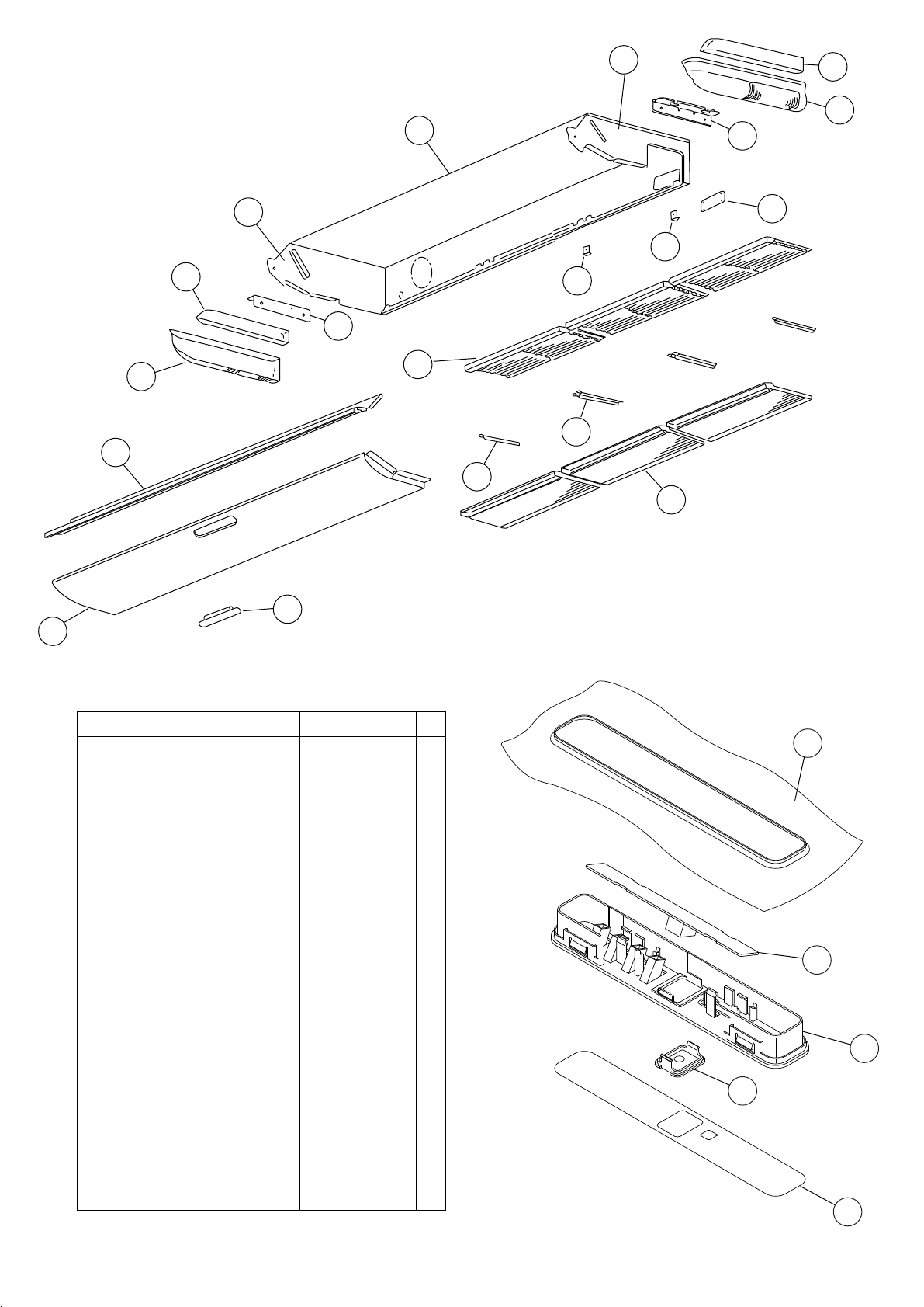
PARTS
INDOOR UNIT
3
1
15
16
18
2
14
17
15
19
4
11
9
6
8
14
7
5
13
Ref. Description Part number
1 Kit (Base Sub Assy) 9371360010
2 Panel Left Sub Assy 9360427014
3 Kit (Panel Right Assy) 9371361017
4 Cover (Top) 9359737001
5 Intake Grille 9359738008
6 Air Filter 9359739005
7 Filter Guide R 9359692003
8 Filter Guide L 9359693000
9 Front Panel 9359734000
10 Indicator PCB Assy 9705891043
11 PCB Holder 9359736004
12 Receiver Cover 9359714002
13 Hole Cover 9359691006
14 Hinge Plate (Grille) 9359694007
15 Hanger Bracket 9359742005
16 Cover (Decoration)-R 9359744009
17 Cover (Decoration)-L 9359745006
18 Kit (Side Cover R) 9371364018
19 Kit (Side Cover L) 9371365015
20 Badge 9359735090
9
10
11
12
20
2008.01.30
18
Page 20

INDOOR UNIT
Drain pan
Flap
Ref.
Description Part number
2 Panel Left Sub Assy 9360427014
3 Kit (Panel Right Assy) 9371361017
21 Evaporator Assy 9372585078
22 Distributor Assy 9371325378
23 Coupling Pipe Assy 9373038405
24 Kit (Panel pipe-L) Sub Assy 9371362014
25 Kit (Panel pipe-R) Sub Assy 9371363011
26 Reinforcement Metal 9359697008
Drain Pan Sub Assy 936042901827
28 Flap Assy 9359731009
29 Bushing 9359733003
30 Flap Spring 9359730002
31 Sector Gear 9359729006
32 Pinion 9359728009
33 Motor Base 9359727002
34 Step Motor V 9900297015
35 Kit (Separate Wall Sub Assy) 9371366029
36 Pipe Fixture Metal 9359688006
-- Drain Cap 9358746004
-- Pipe Thermistor 9900022020
-- Thermistor Spring A
313728262708
28
24
27
33
35
23
25
22
21
36
26
29
28
2
27
3
30
31
33
34
32
3
2008.01.30
28
19
Page 21

51
INDOOR UNIT
Louver Base Sub Assy
47
48
43
41
Ref. Description Part number
41 Louver Base Sub Assy 9360432025
42 Louver 9359719007
43 Rod (Motor) 9359723004
44 Louver Link 9359726005
45 Louver Base 9359718000
46 Louver Spring 9359720003
47 Louver Stopper 9359724001
48 Louver Rod 9359725008
49 Step Motor H 9900297015
50 Louver Insulation R 9359721000
51 Louver Insulation L 9359722007
44
46
45
49
42
50
2008.01.30
20
Page 22

INDOOR UNIT
Fan motor
73
67
74
74
61
73
72
63
63
61
71
72
69
70
68
62
Ref. Description Part number
61 Motor Mount 9377999016
62 Fan Motor Assy 9602389018
63 Motor Band A assy 9374647019
64 Motor Band B 9374648023
65 Reinforcement Motor Band 9378000018
66 Rubber 9385102002
67 Casing 9359704003
68
Kit (Cover Casing) Sub Assy
69 Sirocco Fan Assy 9359701002
70 Joint Assy 9378038011
71 Shaft 9359707004
72 Shaft Holder Bracket 9359686002
73 Bearing B Assy 9357921006
74 Shaft Holder Fixture 9359687009
9371367019
2008.01.30
62
64
66
65
64
21
Page 23
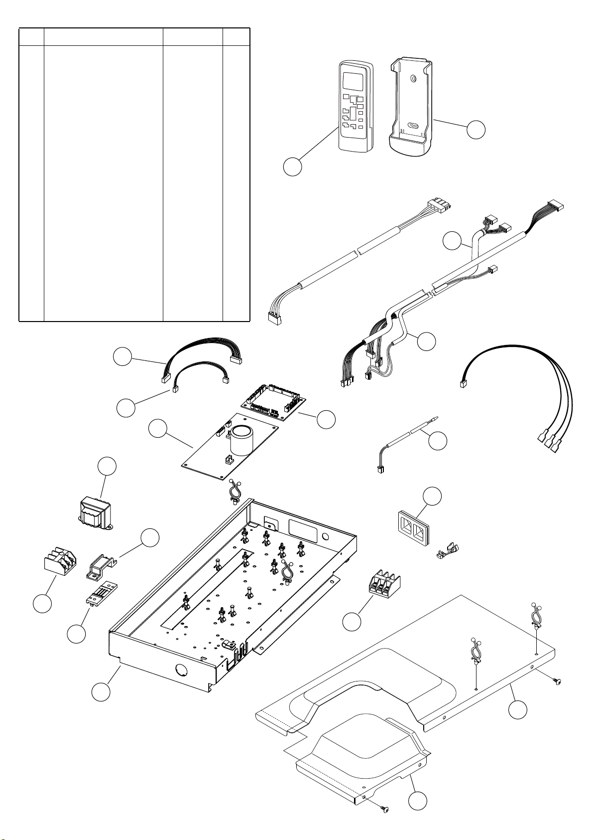
Ref. Description Part number
81 Control Box Assy 9377912015
82 Control Box A 9359712008
83 Control Box B 9359713005
84
Controller PCB Assy (30LBT)
84
Controller PCB Assy (36LBT)
85 Power Supply PCB Assy 9707398076
86 Terminal 3P 9703345012
87 Terminal 3P 9306489045
88 Reactor Assy 9707457018
89 Rubber Bushing 9357376004
91 Cord Clamp-A 9359820017
92 Cord Clamp-B 9359821014
93 Reactor Assy 9707457018
94 Room Thermistor 9703299025
95 Wire Assy (Connector) 9707442021
96 Wire Assy (Connector) 9703339028
97 Wire Assy (Connector) 9702319014
98 Wire Assy (Connector) 9702318017
99 Remote Control 9315885012
100 Remote Control Holder 9305642014
9707393279
9707393286
INDOOR UNIT
Control unit
100
99
97
87
98
95
96
84
85
94
88
89
91
86
92
2008.01.30
81
82
83
22
Page 24

OUTDOOR UNIT
4
1
6
3
7
8
Ref. Part numberDescription
1 Top Panel Sub Assy 9374417032
2 Front Panel 9374094066
3 Fan Guard 9374330010
4 Grip Side 9374173013
5 Service Panel Sub Assy 9374415052
6 Right Panel Sub Assy 9374416127
7 Emblem Rear 9372171011
2
8 Valve Cover 9374174010
2008.01.30
5
23
Page 25

OUTDOOR UNIT
14
12
13
15
11
Ref. Part numberDescription
11 Base Assy 9374166138
12 Condenser A Assy 9374433056
13 Separate Wall 9374413188
14 Fan Motor 9602717019
15 Propeller Fan Assy 9366378020
2008.01.30
24
Page 26

26
24
21
33
OUTDOOR UNIT
22
32
23
34
29
25
27
26
30
28
31
Ref.
21 Accumulator 9385005006
22 4-Way Valve 9900164010
23 Solenoid 9970055034
24 Pressure Switch 9900186012
25 Compressor Assy 9372558126
26 Accumulator Support Assy 313986353804
27 Check Joint Assy 9372802038
28 Expansion Valve Assy 9370947144
29 Coil (Expansion Valve) 9900057039
30 3-Way Valve Assy 9377959010
31 3-Way Valve Assy 9377958013
32 Inlet Pipe (Cond) A Assy 9373461067
33 Outlet Pipe (Cond) A Assy 9374266104
34 Strainer Assy 9372524015
Part numberDescription
2008.01.30
25
Page 27

OUTDOOR UNIT
41
44
42
Ref. Part numberDescription
41 Inverter Case 9375314019
42 TR PCB Assy (IPM) 9707669039
43 ACTPM 9707592016
44 Choke Coil 9900366018
45 Capacitor PCB Assy 9707257021
46 PCB Case Assy 9375316020
47 Controller PCB Assy (30)
47 Controller PCB Assy (36)
48 Power Supply PCB Assy 9707128161
49 Terminal 9900203023
50 Thermistor 9704265012
51 Discharge Thermitor 9900461003
52 Thermistor (Outdoor) 9900463007
53 Compressor Thermistor 9900466008
54
Heat Exchanger Thermistor
55 Wire (Pressure Switch) 9367595082
9707667059
9707667066
9900462000
43
45
50
48
46
2008.01.30
52
Connector :
Yellow
51
53
Connector :
White
26
Connector :
Blue
Connector :
Red
47
49
55
54
Page 28

STANDARD ACCESSORIES
INDOOR UNIT
Name and Shape Q'ty Part numberApplication
Drain hose
insulation
VT wire
Coupler heat insulator
(large)
Coupler heat insulator
(small)
Nylon fastener
Special nut A
(large flange)
Special nut B
(small flange)
Installation
template
Auxiliary pipe
assembly
1
1
2
1
Large
4
Small
4
4
4
1
1
Adhesive type 70 x 230
For fixing the drain hose
L 280 mm
For indoor side pipe joint
(large pipe)
For indoor side pipe joint
(small pipe)
For fixing the coupler heat
insulator
For installing indoor unit
For installing indoor unit
For positioning the indoor unit
For connecting the piping
9360464002
313806350303
9378173569
9378173521
9301501001
312300787605
313005446653
313005446759
9360022004
9374714025
Remote
control
Remote control
holder
Battery
Tapping screw
For air conditioner operation
1
For installing remote control
1
on the wall
For remote control
2
For mounting the remote
2
control holder
OPTIONAL PARTS
The following options are available
Drain pump unit : UTR-DPB241 (P/N 9034087001)
Round duct : UTD-RF204 (P/N 9093160004)
Wired remote control : UTB-*UD
OUTDOOR UNIT
Name and Shape Q'ty Part numberApplication
Drain pipe
For outdoor unit drain piping work
(May not be supplied, depending on
1
the model)
9315885012
9305642014
0600185534
0700019098
9303029015
2008.01.30
Drain cap
Installation
(seal)
2
For filling in a gap at the entrance of
1
connection cords
27
313166024302
9374756018
Page 29

0801G3353
 Loading...