

Page 1

R410A
2.
DUCT TYPE :
AR 18LUAD, AR 24LUAN
AR 18LUAL
D2D_AR001E/06
2007.06.12
Page 2
2-1. FEATURE
MODEL :
AR 18LUAD / AO 18LMAKL
AR 18LUAL / AO 18LMAKL
AR 24LUAN / AO 24LMAKL
DUCT TYPE
AR18 - AR24L
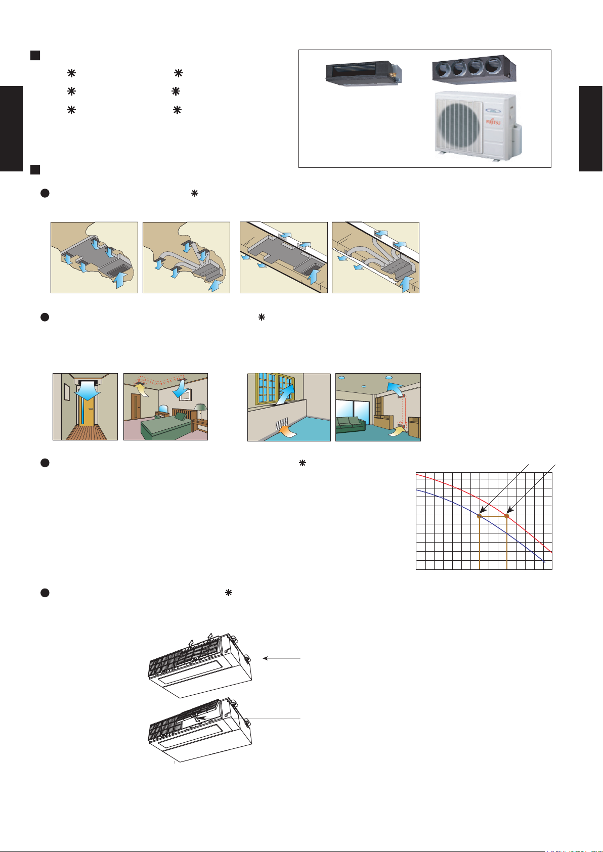
FEATURES
Installation styles (AR 24L)
DUCT TYPE
AR18 - AR24L
Embedded in Ceiling
Hanging from Ceiling
Universal design indoor unit (AR 18L)
Since vertical and horizontal installation is possible, and the intake direction can also be selected
from two directions, flexible installation is possible.
Ceiling concealed Floor concealed
Low static pressure mode function (AR 24L)
1. Low static pressure mode 1 air volume at 70Pa (fan speed:high)
2. Normal Mode Air volume at 100Pa (fan speed:high)
230V
/h)
3
1 2
When installed, normal middle static pressure mode, and low static
pressure mode can be selected by switching over using DIP switch
on the board in the control box. Therefore, these models can be
operated under the wide range of conditions.
Slim & compact design (AR 24L)
In the case of bottom suction type, as seen from lower rear part.
Control Box that has been convex shape
is now united with main unit (DIP Switch is
located on the internal substrate.)
One-touch operating and easy-to-install
long-life filter (optional)
In addition to the slim height of 270 mm which is our sales point, further
compactification is attained by reducing 65 mm from the width with the
flanking control box embedded inside the chassis.
Air volume (m
0 70 100
Static pressure (Pa)
- (02 - 01) -
Page 3
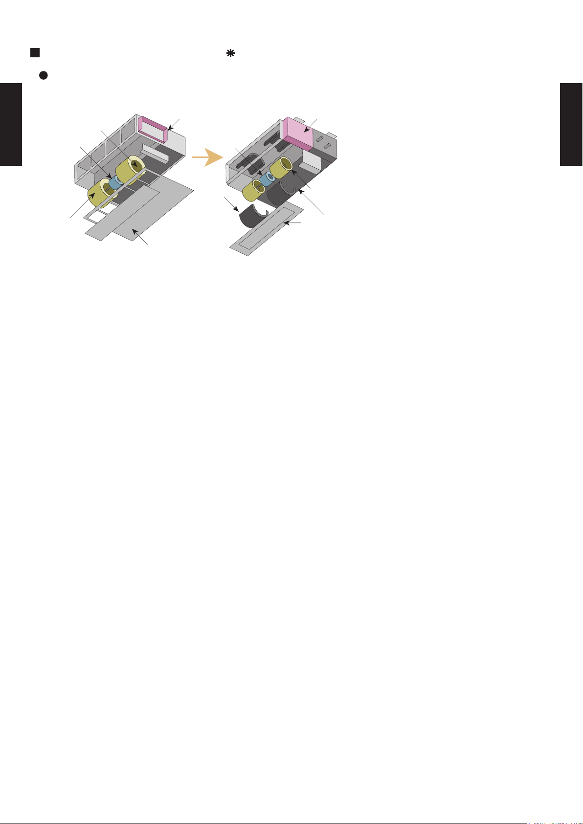
EASY MAINTENANCE (AR 24L)
In the case of rear suction type, as seen from lower rear part.
DUCT TYPE
AR18 - AR24L
Conventional model
1
3
4
New model
4
1
1. Control box
2. Fan casing
3. Fan
4. Motor
2
2
3
Bottom panel: 2 units
Large bottom panel: 1 unit
Structural improvement is attained by making the bottom panel two pieces, front and
rear, and the internal fan casing is also made dismountable in two pieces namely,
upper and lower ones.
The motor and fan maintenance and dismounting can be made easily by removing
the rear panel and lower part of the casing with the main chassis installed.
DUCT TYPE
AR18 - AR24L
- (02 - 02) -
Page 4

2-2. REMOTE CONTROLLER
2-2-1. WIRED REMOTE CONTROLLER
DUCT TYPE
AR18 - AR24L
FEATURES
Various timer setup (ON / OFF / WEEKLY) are possible.
Equipped with weekly timer as standard function.
(2 times Start / Stop per day for a week)
SUMOTUWETH FR SA
7
3126 9
15 18 21
When setting up a timer, operation mode and a temperature
setup can be changed.
When a failure occurs,the error code is displayed. (Maximum of 16)
Error indication.(A maximum of 16 error histories are memorizable.)
Up to 16 indoor units can be simultaneously controlled.
Anti freeze and energy saving operation are possible.
Easy installation with a slim shape with no bulge in the back.
The room temperature can be controlled by being detected the temperature
accurately with built-in thermo sensor.
High performance and compact size
Three functions are combined in
one unit.
controller
Built-in timers
Wired
remote
Weekly
timer
Setback timerWeekly timer
Setback
timer
DUCT TYPE
AR18 - AR24L
Possible to set ON/OFF time to operate twice each day
of the week.
SUMOTUWETH FR SA
7
3126 9
15 18 21
Setup screen example
(Set to Wednesday: 8:00 to 20:00.)
0 3 6 9 12 15 18 21 Time
Easy-to-understand time bar display
24°C
SUMOTUWETH FR SA
7
3126 9
15 18 21
Screen
after setup
At "Weekly timer" + "Set back timer" setup
24°C 28°C 24°C
Timer
area
Operation
area
Possible to set temperature for two time spans and
for each day of the week.
SUMOTUWETH FR SA
3126 9
15 18 21
Setup screen example
(Set from Sunday to Saturday: 12:00 to 15:00, 28 °C.)
0 3 6 9 12 15 18 21 Time
24°C
0 3 6 9 12 15 18 21 Time
28°C
28°C
Simple installationEasy-to-understand operation
Components are compatible with standard
switch boxes. Flat back construction allows
equipment to be installed wherever it is
needed.
[
Variable timer control
]
The operation/display sections are zoned according to time and operation, enabling variable
programming to match application.
- (02 - 03) -
European
switch box
JIS box
Page 5
DUCT TYPE
AR18 - AR24L
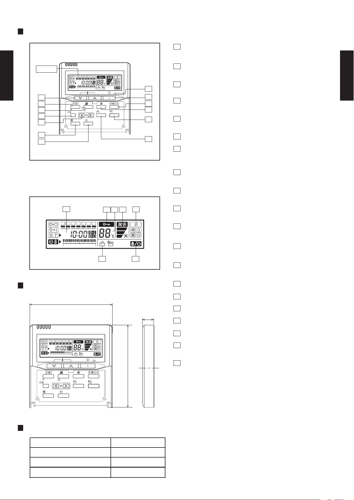
FUNCTIONS
Display
2
7
8
9
10
11
12
Display panel
SET BACK
SUMOTUWETH FR
3 6 9
CLOCK ADJUST
DELETE SET
12 15 18 21
DAY
DAY OFF
1
START/STOP button
Pressed to start and stop operation.
2
Set temperature button
SA
13
1
3
ENERGY
SAVE
THERMO
SENSOR
4
6
Selects the setting temperature.
3
Master control button
Selects the operating mode(AUTO, HEAT, FAN, COOL, DRY).
4
Fan control button
Selects the fan speed (AUTO, LOW, MED, HIGH).
5
Energy save button
DUCT TYPE
AR18 - AR24L
Turns the energy efficient mode on and off.
6
5
Thermo sensor
7
Timer mode (CLOCK ADJUST) button
Selects the timer mode (OFF TIMER, ON TIMER, WEEKLY TIMER)
Set the current time.
8
Day (DAY OFF) button
Temporarily cancels of one day timer.
9
Set back button
Pressed to select the set back timer.
14
SUMOTUWETH FR
3 6 9
DIMENSION
120
SUMOTUWETH FR
CLOCK ADJUST
SET BACK
DELETE SET
3 6 9
SA
12 15 18 21
DAY
DAY OFF
12 15 18 21
ENERGY
SAVE
SA
THERMO
SENSOR
15
1617 18
1920
[ Unit : mm ]
120
10
Set time button
Pressed to select the set back timer.
11
Delete button
The schedule of a weekly timer is deleted.
12
Set button
Sets the date, hour, minute and on-off time.
13
Operation lamp
Lights during operation and when the timer is on.
14
Timer and clock display
15
Operation mode display
16
Fan speed display
17
17
Central control display
18
Temperature display
19
Standby display
Indicates during the oil recovery and defrosting operation.
20
Energy save display
Front View
SPECIFICATION
SIZE (H x W x D mm) 120 x 120 x 17
WEIGHT ( g ) 160
CABLE LENGTH ( m )
POWER ( V )
10
12
- (02 - 04) -
Page 6
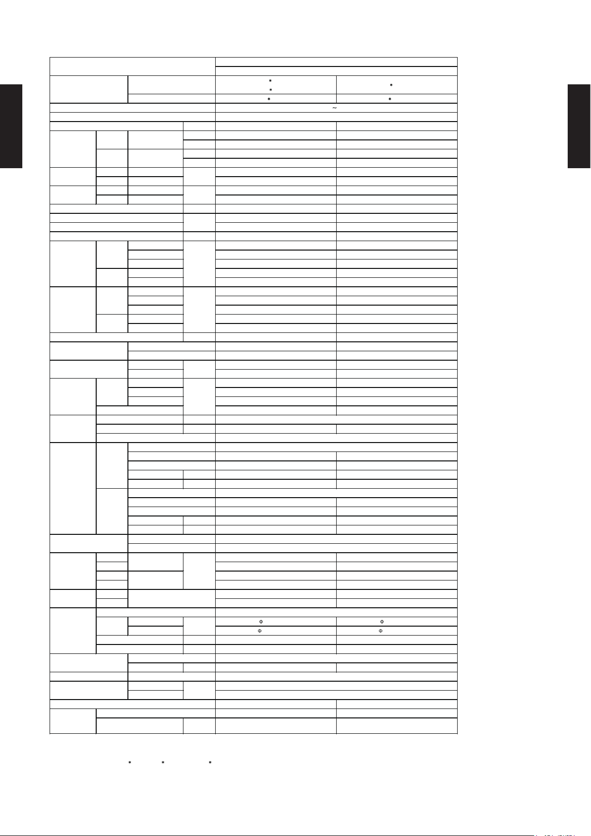
2-3. SPECIFICATIONS
AR 18LUAD
AR 18LUAL
AO 18LMAKL AO 24LMAKL
Fin Pitch mm
1.3 1.3
Fin Pitch mm
1.45 1.45
6.35 (1/4 inc.) 9.52 (3/8 inc.)
12.70 (1/2 inc.) 15.88 (5/8 inc.)
ABS Steel
Outer diameter 26.0
Inner diameter 21.5
Outer diameter 38.0
Inner diameter 36.0
DUCT TYPE
INVERTER HEAT PUMP TYPE
MODEL NAME
OUTDOOR
INDOOR
AR 24LUAN
TYPE
230V 50Hz
CAPACITY
COOLING
RATED / *MAX.
HEATING
RATED / *MAX.
AVAILABLE VOLTAGE RANGE
198 - 264V
EUROPEAN ENERGY LABEL
POWER SOURCE
INPUT POWER
kW
CURRENT
A
dB(A)
OUTDOOR
FAN MOTOR OUTPUT
W
fin
OUTDOOR
Coil
Copper tube
fin
Rows × Stages
Rows × Stages
Coil
COMPRESSOR
TYPE
Copper tube
DC TWIN ROTARY(INVERTER)
STARTING METHOD
Permanent Starting Condenser Method
INDOOR
FAN SPEED
HEAT
EXCHANGER
TYPE
INDOOR
NOISE LEVEL
(SOUND
PRESSURE)
COOL/HEAT
INDOOR
STARTING CURRENT
kW/kW
MOISTURE REMOVAL
AIR
CIRCULATION
COP
OUTDOOR
m3/h
INDOOR
EER
OUTDOOR
r.p.m
Galvanized steel sheet
Beige (10YR7.5 / 1.0NN)
CASING COLOR
OUTPUT
RECOMMENDED STATIC PRESSURE
FAN TYPE × Q'ty
DIMENSIONS
(H × W × D)
NET
mm
GROSS
WEIGHT
NET /
GROSS
kg(lbs)
PIPE
CONNECTION METHOD
MAX. HEIGHT
FLARE
SIZE
mm
MAX. LENGTH
REFRIGERANT
TYPE
R410A
REFRIGERANT OIL
TYPE
Synthetic (POE oil)
OPERATION(OUTDOOR)
°C
0 to 43
-10 to 24
REMOTE CONTROLLER
DRAIN PIPE
MATERIAL
SIZE
DUCT TYPE
AR18 - AR24L
COOLING RATED / *MAX. 1.70 / 1.99 2.53 / 2.96
HEATING RATED / *MAX. 1.90 / 2.40 2.43 / 2.93
COOLING RATED / *MAX. 7.4 / 8.8 11.1 / 12.9
HEATING RATED / *MAX. 8.3 / 10.5 10.6 / 12.8
High 800 1490
Med 640 1340
Low 500 1200
High 2800 2800
Low - -
High 1040 980
Med 890 890
Low 750 810
High 780 780
Low 400 400
INDOOR Sirocco × 2 Sirocco × 2
OUTDOOR Propeller × 1 Propeller × 1
INDOOR 45 70
OUTDOOR 65 65
High 38.0 / 38.0 34.0 / 34.0
Med 34.0 / 34.0 32.0 / 32.0
Low 30.0 / 30.0 29.0 / 29.0
COOLING B C
kW 5.20 / 5.90 7.10 / 8.00
BTU/h 17800 / 20100 24200 / 27300
kW 6.20 / 7.50 8.00 / 9.00
BTU/h 21200 / 25600 27300 / 30700
A 10.0 10.0
3.06 2.81
3.26 3.29
l/h (pints/h) 1.7 (3.6) 1.5 (3.2)
Pa 0 to 40 30 to 150
50.0 / 52.0 52.0 / 54.0
DUCT TYPE
AR18 - AR24L
W 1300 1300
Hydrophilic coating Hydrophilic coating
3 × 14 2 × 14
Coil Dimensions mm
Coil Dimensions mm
INDOOR
OUTDOOR
INDOOR 217 × 953 × 595 270 × 1135 × 700
OUTDOOR 650 × 830 × 320 650 × 830 × 320
INDOOR 324 × 1075 × 686 300 × 1300 × 790
OUTDOOR 743 × 984 × 413 743 × 984 × 413
INDOOR 25 / 29 (55 / 64) 41 / 48 (90 /106)
OUTDOOR 54 / 58 (119 / 128) 54 / 58 (119 / 128)
LIQUID
GAS
m 25 25
m 15 15
CHARGE g 1500 1800
COOLING
HEATING
294 × 700 × 39.9 294 × 1000 × 26.6
Hydrophilic coating Hydrophilic coating
2 × 30 2 × 30
630 × 901 × 36.38 630 × 901 × 36.38
WIRED (AR-3TA1) WIRED (AR-3TA1)
Note : Specifications are based on the following conditions.
Cooling : Indoor temperature of 27°CDB/19°CWB, and outdoor temperature of 35°CDB/24°CWB.
Heating : Indoor temperature of 20°CDB/15°CWB, and outdoor temperature of 7°CDB/6°CWB.
Standard static pressure : 0 Pa (AR 18LUAD, AR 18LUAL) 30Pa (AR 24LUAN)
Pipe length : 7.5 m, Height difference : 0 m. (Outdoor unit - Indoor unit)
Sound pressure level : Install a 2m duct to the outlet port and a 1m duct to the suction port and measure.
*The maximum current and the maximum input value are the maximum values when operated within the operation (temperature) range.
mm
- (02 -05) -
Page 7
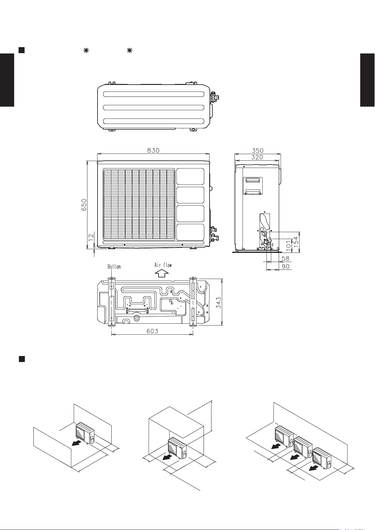
2-4. DIMENSIONS
2-4-1. OUTDOOR UNIT
MODEL : AO 18L, AO 24L
DUCT TYPE
AR18 - AR24L
Top view
(Unit : mm)
DUCT TYPE
AR18 - AR24L
MOUNTING POSITION
When there are obstacles at the
back or front sides.
Front view
Bottom view
When there are obstacles at the
back, side(s), and top.
600 mm or more
Side view
When there are obstacles at the
back, side with the installation of
more than one unit.
AIR
600 mm
or more
100 mm
or more
100 mm
or more
AIR
- (02 - 06) -
250 mm or more
(Service space)
300 mm
or more
250 mm
or more
AIR
250 mm
or more
300 mm
or more
Page 8
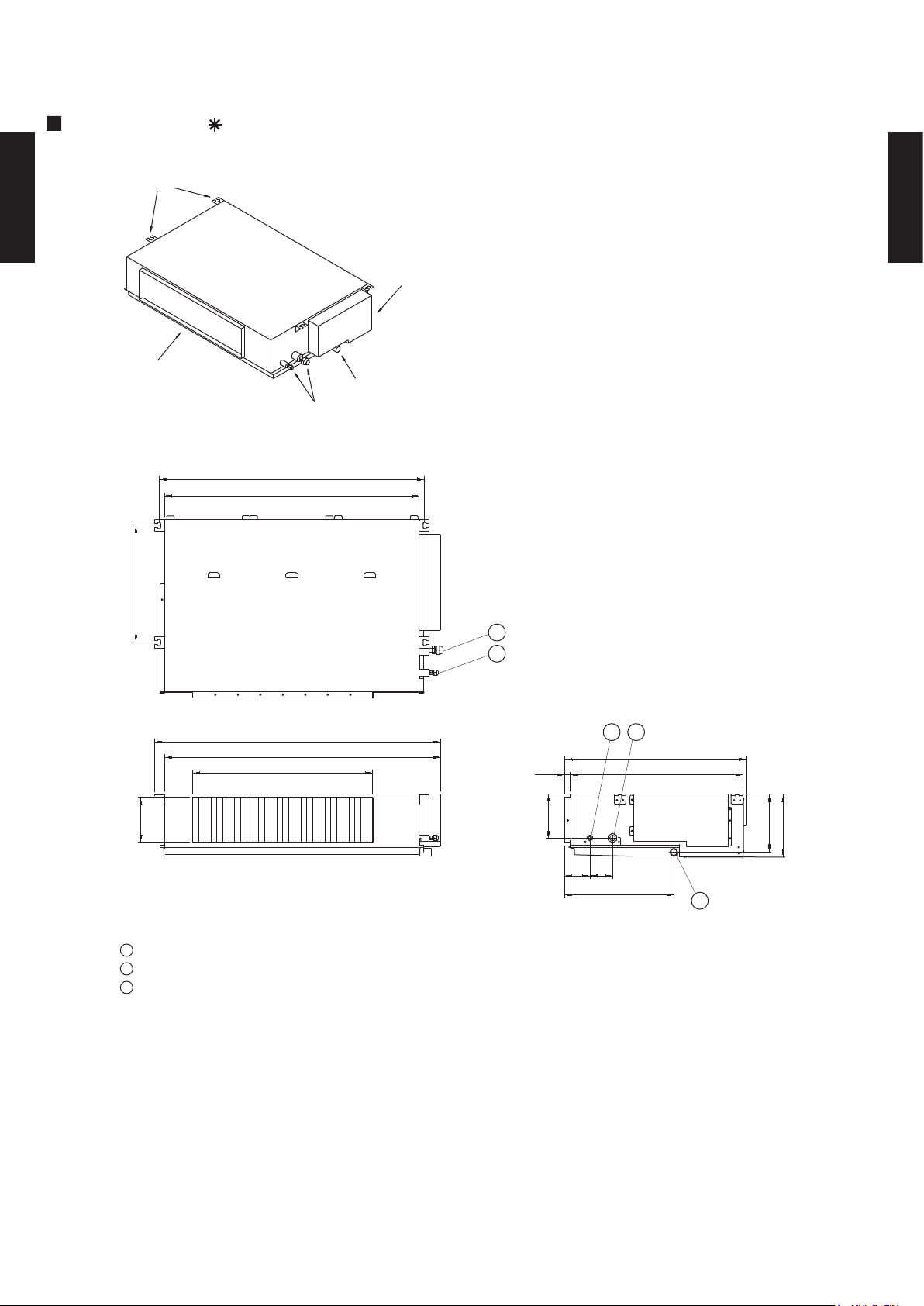
2-4-2. INDOOR UNIT
MODEL : AR 18L
BRACKETS
DUCT TYPE
AR18 - AR24L
AIR FLOW OUTLET
DRAIN PORT
COUPLING PIPE ASSY
886
850
CONTROL BOX
(Unit : mm)
DUCT TYPE
AR18 - AR24L
390
953
920
600
150
1
Refrigerant piping flare connection (Gas)
2
Refrigerant piping flare connection (Liquid)
3
Drain piping connection
1
2
12
605
57520
150
85 75
364
194
217
3
- (02 - 07) -
Page 9
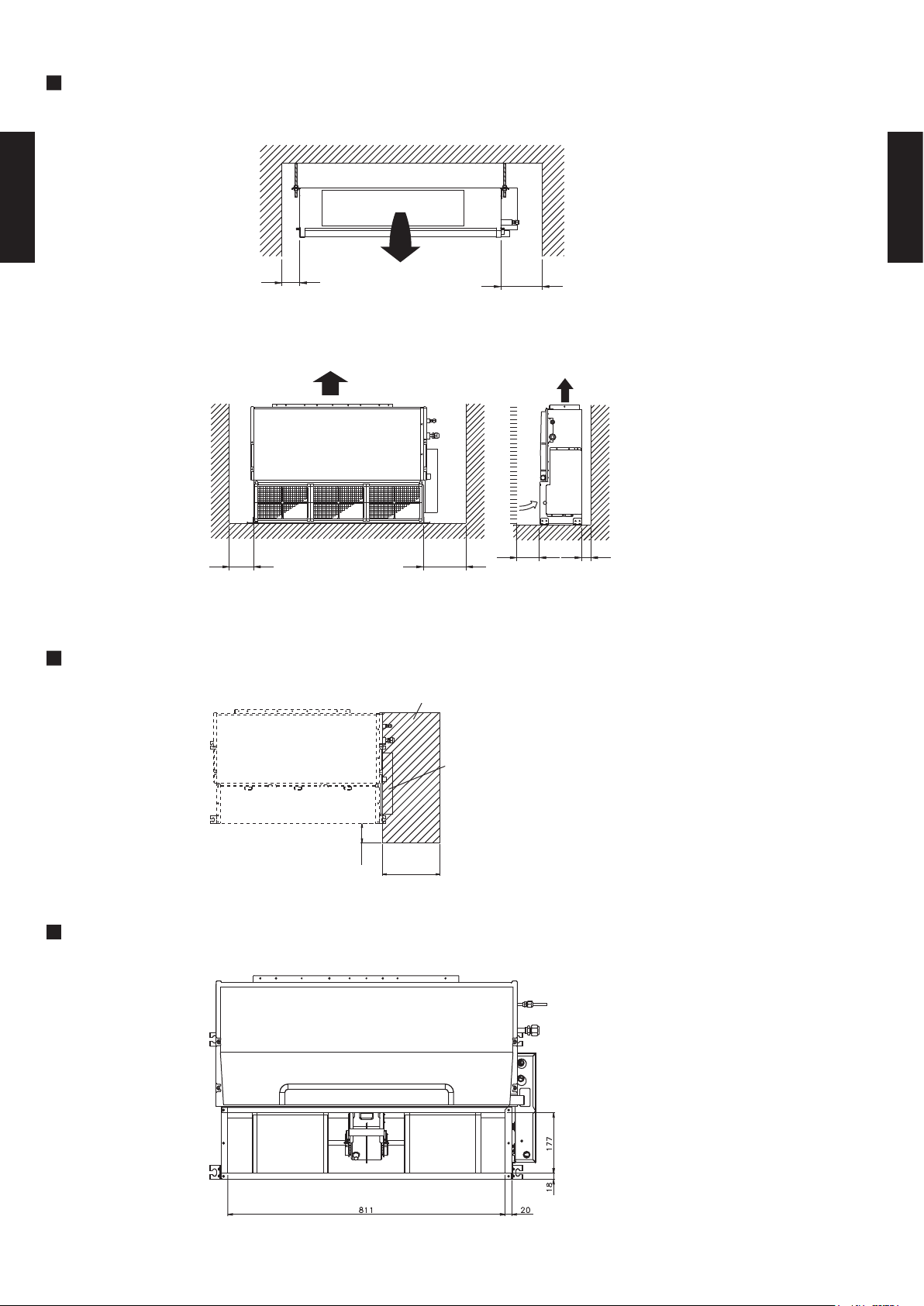
MOUNTING POSITION
Strong and durable ceiling
Indoor unit
DUCT TYPE
AR18 - AR24L
Left
side
100mm
or more
Left
side
100mm
or more
Strong and durable floor
Right side
(PIPE side)
300mm
or more
300mm
or more
30mm
or more
Right
side
30mm
or more
DUCT TYPE
AR18 - AR24L
MAINTENANCE HOLE
Unit
100mm
or more
BOTTOM AIR INTAKE HOLE
Maintenance hole
Control box
300mm
or more
(Unit : mm)
- (02 - 08) -
Page 10

DUCT TYPE
AR18 - AR24L
MODEL : AR 24L
Front view
(Unit : mm)
DUCT TYPE
AR18 - AR24L
Side view (L)
Top view
Rear view
Refrigerant piping flare connection (Gas)
Refrigerant piping flare connection (Liquid)
Drain piping connection.
Drain piping connection with cap.
Knock out hole for fresh air.
Side view (R)
- (02 - 09) -
Page 11

DUCT TYPE
AR18 - AR24L
MOUNTING POSITION
DUCT TYPE
AR18 - AR24L
300mm
or more
MAINTENANCE HOLE
It shall be possible to install and remove
the control box.
WHEN USING A SQUARE DUCT
150mm
or more
It shall be possible to install and remove
the control box, fan units and filter.
(Unit : mm)
BOTTOM AIR INTAKE HOLE
(Unit : mm)
- (02 -10) -
Page 12

2-5. REFRIGERANT CIRCUIT
MODEL : AR 18L / AO 18L
DUCT TYPE
AR18 - AR24L
DUCT TYPE
AR18 - AR24L
MODEL : AR 24L / AO 24L
- (02 -11) -
Page 13

2-6. WIRING DIAGRAMS
2-6-1. OUTDOOR UNIT
MODEL : AO 18L, AO 24L
DUCT TYPE
AR18 - AR24L
DUCT TYPE
AR18 - AR24L
- (02 -12) -
Page 14

2-6-2. INDOOR UNIT
MODEL : AR 18L
DUCT TYPE
AR18 - AR24L
DUCT TYPE
AR18 - AR24L
MODEL : AR 24L
- (02 -13) -
Page 15

2-7. CAPACITY TABLE
Indoor temperature
18°CDB
21°CDB
23°CDB
26°CDB
27°CDB
29°CDB
30°CDB
32°CDB
23°CWB
12°CWB
15°CWB
16°CWB
18°CWB
19°CWB
21°CWB
22°CWB
Outdoor temperature
Outdoor temperature
19°CWB
21°CWB
22°CWB
23°CWB
12°CWB
15°CWB
16°CWB
18°CWB
Indoor temperature
18°CDB
21°CDB
23°CDB
26°CDB
27°CDB
29°CDB
30°CDB
32°CDB
2-7-1. COOLING CAPACITY
This table is created using the maximum capacity.
MODEL : AR 18L / AO 18L
AFR 17.3
DUCT TYPE
AR18 - AR24L
MODEL : AR 24L / AO 24L
(°CDB) TC SHC PI TC SHC PI TC SHC PI TC SHC PI TC SHC PI TC SHC PI TC SHC PI TC SHC PI
0 3.63 3.05 0.30 3.70 2.88 0.31 3.77 3.05 0.31 3.88 3.17 0.32 3.93 3.15 0.32 4.01 3.09 0.32 4.05 3.06 0.32 4.09 3.19 0.33
5 3.73 3.12 0.38 3.82 2.96 0.39 3.91 3.15 0.39 4.05 3.31 0.40 4.10 3.29 0.40 4.20 3.24 0.41 4.25 3.22 0.41 4.29 3.36 0.42
10 4.42 3.70 0.60 4.53 3.51 0.62 4.64 3.74 0.62 4.83 3.95 0.64 4.91 3.93 0.64 5.04 3.89 0.65 5.10 3.86 0.66 5.15 4.04 0.66
15 4.16 3.46 0.67 4.26 3.27 0.68 4.37 3.51 0.69 4.55 3.71 0.70 4.62 3.70 0.71 4.75 3.67 0.72 4.81 3.65 0.73 4.87 3.82 0.73
20 4.08 3.38 0.76 4.17 3.20 0.77 4.27 3.42 0.78 4.43 3.62 0.79 4.50 3.61 0.80 4.63 3.58 0.81 4.70 3.56 0.82 4.75 3.74 0.82
25 5.28 4.40 1.24 5.41 4.17 1.25 5.53 4.44 1.26 5.74 4.69 1.28 5.83 4.67 1.29 5.99 4.62 1.30 6.06 4.60 1.31 6.13 4.82 1.32
30 5.04 4.18 1.39 5.19 3.98 1.40 5.31 4.25 1.41 5.50 4.50 1.44 5.59 4.49 1.45 5.76 4.45 1.47 5.84 4.43 1.47 5.91 4.65 1.48
35 5.35 4.41 1.92 5.45 4.16 1.93 5.59 4.47 1.95 5.80 4.74 1.98 5.90 4.73 1.99 6.09 4.70 2.02 6.18 4.68 2.03 6.27 4.94 2.04
40 5.04 4.15 2.14 5.11 3.89 2.15 5.23 4.18 2.16 5.44 4.45 2.19 5.55 4.45 2.21 5.74 4.43 2.24 5.83 4.42 2.26 5.93 4.68 2.28
43 4.79 3.92 2.21 4.87 3.69 2.22 4.99 3.98 2.23 5.20 4.26 2.26 5.31 4.26 2.28 5.50 4.24 2.32 5.61 4.24 2.33 5.71 4.51 2.34
DUCT TYPE
AR18 - AR24L
AFR 24.8
(°CDB) TC SHC PI TC SHC PI TC SHC PI TC SHC PI TC SHC PI TC SHC PI TC SHC PI TC SHC PI
0 4.92 4.28 0.45 5.02 4.04 0.46 5.12 4.27 0.46 5.26 4.44 0.47 5.33 4.41 0.47 5.44 4.33 0.48 5.49 4.29 0.48 5.54 4.47 0.48
5 5.06 4.37 0.57 5.17 4.14 0.58 5.30 4.41 0.59 5.49 4.63 0.60 5.56 4.61 0.60 5.70 4.54 0.61 5.76 4.50 0.61 5.82 4.70 0.62
10 6.00 5.18 0.90 6.15 4.91 0.92 6.30 5.23 0.93 6.55 5.53 0.95 6.65 5.51 0.96 6.83 5.45 0.97 6.91 5.41 0.98 6.99 5.65 0.98
15 5.64 4.85 0.99 5.78 4.58 1.02 5.93 4.91 1.03 6.16 5.20 1.05 6.26 5.18 1.06 6.44 5.13 1.07 6.52 5.10 1.08 6.60 5.35 1.09
20 5.53 4.74 1.12 5.65 4.47 1.14 5.79 4.79 1.15 6.01 5.07 1.18 6.11 5.06 1.19 6.28 5.01 1.21 6.37 4.99 1.22 6.45 5.24 1.23
25 7.16 6.16 1.84 7.34 5.83 1.86 7.50 6.22 1.88 7.78 6.57 1.90 7.90 6.54 1.92 8.12 6.47 1.94 8.22 6.44 1.95 8.31 6.74 1.96
30 6.84 5.85 2.07 7.03 5.57 2.09 7.19 5.96 2.10 7.46 6.30 2.14 7.59 6.28 2.15 7.81 6.23 2.18 7.91 6.20 2.19 8.02 6.52 2.21
35 7.25 6.18 2.86 7.39 5.82 2.87 7.58 6.26 2.90 7.86 6.64 2.94 8.00 6.62 2.96 8.26 6.58 3.00 8.38 6.56 3.02 8.50 6.92 3.04
40 6.83 5.80 3.18 6.93 5.45 3.19 7.09 5.86 3.21 7.38 6.24 3.26 7.52 6.23 3.28 7.78 6.20 3.33 7.91 6.19 3.35 8.04 6.56 3.40
43 6.49 5.48 3.29 6.60 5.17 3.30 6.76 5.57 3.32 7.05 5.96 3.37 7.20 5.96 3.39 7.46 5.94 3.44 7.61 5.94 3.46 7.75 6.31 3.49
AFR: Air flow rate (m3/min)
TC : Total capacity (kW)
SHC: Sensible Heat capacity (kW)
PI : Power Input (kW)
- (02 -14) -
Page 16

2-7-2. HEATING CAPACITY
30°CDB
Outdoor temperature
Indoor temperature
16°CDB
18°CDB
20°CDB
23°CDB
25°CDB
27°CDB
(°CWB)
Outdoor temperature
Indoor temperature
16°CDB
18°CDB
20°CDB
23°CDB
25°CDB
27°CDB
30°CDB
This table is created using the maximum capacity.
MODEL : AR 18L / AO 18L
AFR 17.3
DUCT TYPE
AR18 - AR24L
(°CDB) (°CWB) TC PI TC PI TC PI TC PI TC PI TC PI TC PI
-10 -11 5.77 2.45 5.68 2.53 5.50 2.60 5.32 2.68 5.23 2.72 5.06 2.80 4.88 2.84
-5 -6 5.67 2.46 5.59 2.53 5.43 2.60 5.27 2.67 5.19 2.71 5.03 2.78 4.87 2.82
0 -1 5.91 2.42 5.83 2.49 5.69 2.55 5.54 2.61 5.46 2.64 5.32 2.71 5.17 2.74
2 1 6.09 2.51 6.03 2.56 5.90 2.62 5.78 2.67 5.72 2.70 5.59 2.75 5.47 2.78
7 6 7.73 2.30 7.65 2.35 7.50 2.40 7.35 2.45 7.28 2.47 7.13 2.52 6.98 2.54
10 8 8.03 2.36 7.96 2.41 7.81 2.45 7.67 2.50 7.59 2.52 7.45 2.57 7.30 2.59
15 12 8.23 2.40 8.15 2.45 8.01 2.49 7.86 2.54 7.78 2.56 7.63 2.61 7.49 2.63
20 15 8.39 2.35 8.30 2.40 8.14 2.45 7.98 2.49 7.90 2.52 7.74 2.57 7.57 2.59
24 18 8.51 2.30 8.43 2.35 8.25 2.40 8.08 2.45 7.99 2.48 7.81 2.53 7.64 2.55
MODEL : AR 24L / AO 24L
AFR 24.8
(°CDB)
-10 -11 6.92 2.99 6.81 3.08 6.60 3.18 6.39 3.27 6.28 3.32 6.07 3.42 5.86 3.46
-5 -6 6.80 3.00 6.71 3.09 6.52 3.18 6.33 3.26 6.23 3.31 6.04 3.40 5.85 3.44
0 -1 7.09 2.96 7.00 3.03 6.82 3.11 6.65 3.19 6.56 3.23 6.38 3.30 6.20 3.34
2 1 7.31 3.07 7.23 3.13 7.09 3.20 6.94 3.26 6.86 3.30 6.71 3.36 6.56 3.40
7 6 9.27 2.81 9.18 2.87 9.00 2.93 8.82 2.99 8.73 3.02 8.55 3.08 8.37 3.11
10 8 9.64 2.88 9.55 2.94 9.37 2.99 9.20 3.05 9.11 3.08 8.94 3.13 8.76 3.16
15 12 9.87 2.93 9.78 2.99 9.61 3.04 9.43 3.10 9.34 3.13 9.16 3.18 8.98 3.21
20 15 10.06 2.87 9.97 2.93 9.77 2.99 9.58 3.04 9.48 3.07 9.28 3.13 9.09 3.16
24 18 10.22 2.81 10.11 2.87 9.90 2.93 9.69 2.99 9.59 3.03 9.37 3.09 9.16 3.12
TC PI TC PI TC PI TC PI TC PI TC PI TC PI
DUCT TYPE
AR18 - AR24L
AFR: Air flow rate (m3/min)
TC : Total capacity (kW)
PI : Power Input (kW)
- (02 -15) -
Page 17

2-8. COEFFICIENT OF COMPENSATION FOR PIPE LENGTH
Pipe length (m)
1
Indoor unit is upper
than outdoor unit.
2
Indoor unit is under
than outdoor unit
COOLING
Height
difference H
(m)
Height
difference H
(m)
Pipe length (m)
HEATING
2
Indoor unit is under
than outdoor unit
1
Indoor unit is upper
than outdoor unit.
AND HEIGHT DIFFERENCE
This table is created using the maximum capacity.
MODEL : AR 18L/AO 18L
AR 24L/AO 24L
DUCT TYPE
AR18 - AR24L
5 7.5 10 15 20 25
15 - - - 0.982 0.974 0.966
10 - 0.988 0.982 0.974 0.966
7.5 - 1.000 0.988 0.982 0.974 0.966
5 1.010 1.000 0.988 0.982 0.974 0.966
0 1.010 1.000 0.988 0.982 0.974 0.966
-5 1.002 0.992 0.980 0.974 0.966 0.958
-7.5 - 0.988 0.976 0.970 0.962 0.954
-10 - - 0.972 0.966 0.958 0.950
-15 - - - 0.958 0.951 0.943
5 7.5 10 15 20 25
15 - - - 0.987 0.985 0.983
10 - - 0.993 0.992 0.990 0.988
7.5 - 0.993 0.996 0.994 0.992 0.991
DUCT TYPE
AR18 - AR24L
5 0.979 0.995 0.998 0.997 0.995 0.993
0 0.984 1.000 1.003 1.002 1.000 0.998
-5 0.984 1.000 1.003 1.002 1.000 0.998
-7.5 - 1.000 1.003 1.002 1.000 0.998
-10 - - 1.003 1.002 1.000 0.998
-15 - - - 1.002 1.000 0.998
Height difference H
Indoor unit
H
Outdoor unit
Connection pipe
Indoor unit is upper than outdoor unit.1 Indoor unit is under than outdoor unit.2
Outdoor unit
H
Indoor unit
Connection pipe
- (02 -16) -
Page 18

2-9. ADDITIONAL CHARGE CALCULATION
20g/m
R410A
R410A
1500
40g/m
1800
MODEL : AR 18L/AO 18L
Refrigerant type
Refrigerant amount g
DUCT TYPE
AR18 - AR24L
REFRIGERANT CHARGE
Pipe length m
Additional charge g 0 (Chargeless) +100 +200 +300
10 15 20 25
MODEL : AR 24L/AO 24L
Refrigerant type
Refrigerant amount g
REFRIGERANT CHARGE
Pipe length m 10 15 20 25
Additional charge g 0 (Chargeless) +200 +400 +600
DUCT TYPE
AR18 - AR24L
- (02 -17) -
Page 19

2-10. OPERATION RANGE
Indoor unit Outdoor unit Mode Indoor unit Indoor humidity Outdoor unit
Cooling
Dry
18 to 32 °C 80% or less 0 to 43 °C
Heating 30 °C or less - -10 to 24 °C
Model
Operation Range
AR*18L
AR*24L
AO*18L
AO*24L
DUCT TYPE
AR18 - AR24L
DUCT TYPE
AR18 - AR24L
- (02 -18) -
Page 20

2-11. FAN PERFORMANCE AND AIR FLOW
0 20 40
m3/h
800 720 640
l/s 222 200 178
CFM 471 424 377
m3/h
640 576 512
l/s 178 160 142
CFM 377 339 301
m3/h
500 450 400
l/s 139 125 111
CFM 294 265 235
Fan speed
Hi
Med
Low
Static pressure (Pa)
2-11-1. NORMAL MODE
MODEL : AR 18L
DUCT TYPE
AR18 - AR24L
Q-h Characteristic curve
45
40
35
30
25
20
15
Static pressure(pa)
10
5
0
300 400 500 600 700 800 900 1000
Air flow (m3/h)
100
95
90
85
80
Cooling capacity(%)
75
70
300 400 500 600 700 800 900 1,000
105
103
101
99
97
95
93
91
89
Heating capacity(%)
87
85
300 400 500 600 700 800 900 1,000
Air temp
Capacity
Air flow (m3/h)
Air temp
Capacity
Air flow (m3/h)
- (02 -19) -
Hi
Med
Low
COOLING
HEATING
16.0
15.0
14.0
13.0
12.0
11.0
Air temperature(°C)Air temperature(°C)
10.0
9.0
55.0
53.0
51.0
49.0
47.0
45.0
43.0
41.0
39.0
37.0
35.0
DUCT TYPE
AR18 - AR24L
Page 21

DUCT TYPE
30 50 80 100 120 140 150
m3/h
1490 1410 1270 1150 1020 830 720
l/s 414 392 353 319 283 231 200
CFM 877 830 747 677 600 489 424
m3/h
1340 1240 1110 1000 880 700 -
l/s 372 344 308 278 244 194 -
CFM 789 730 653 589 518 412 -
m3/h
1200 1100 970 870 750 - -
l/s 333 306 269 242 208 - -
CFM 706 647 571 512 441 - -
Static pressure (Pa)
Fan speed
Hi
Med
Low
AR18 - AR24L
MODEL : AR 24L
160
140
120
Q-h Characteristic curve
Hi
Med
Low
DUCT TYPE
AR18 - AR24L
100
80
60
Static pressure(pa)
40
20
0
500 700 900 1100 1300 1500
Air flow (m3/h)
100
Air temp
90
80
Cooling capacity(%)
70
500 600 700 800 900 1,000 1,100 1,200 1,300 1,400 1,500
Capacity
COOLING
16.0
15.0
14.0
13.0
12.0
11.0
Air temperature(°C)Air temperature(°C)
10.0
9.0
Air flow (m3/h)
HEATING
105
100
Air temp
95
Capacity
90
85
Heating capacity(%)
80
500 600 700 800 900 1,000 1,100 1,200 1,300 1,400 1,500
Air flow (m3/h)
- (02 -20) -
55.0
53.0
51.0
49.0
47.0
45.0
43.0
41.0
39.0
37.0
35.0
Page 22

2-11-2. LOW STATIC MODE
30 50 70 100
m3/h
1340 1240 1140 1000
l/s 372 344 317 278
CFM 789 730 671 589
m3/h
1200 1100 1000 870
l/s 333 306 278 242
CFM 706 647 589 512
m3/h
1060 960 860 730
l/s 294 267 239 203
CFM 624 565 506 430
Static pressure (Pa)
Fan speed
Hi
Med
Low
MODEL : AR 24L
DUCT TYPE
AR18 - AR24L
120
100
80
Q-h Characteristic curve
Hi
Med
Low
DUCT TYPE
AR18 - AR24L
Static pressure(pa)
Cooling capacity(%)
Heating capacity(%)
60
40
20
0
500 600 700 800 900 1000 1100 1200 1300 1400 1500
Air flow (m3/h)
105
100
Air temp
95
90
85
80
500 600 700 800 900 1,000 1,100 1,200 1,300 1,400 1,500
Capacity
COOLING
Air flow (m3/h)
HEATING
105
100
Air temp
95
90
85
80
500 600 700 800 900 1,000 1,100 1,200 1,300 1,400 1,500
Capacity
Air flow (m3/h)
16
15
14
13
12
11
Air temperature(°C)Air temperature(°C)
10
9
55
53
51
49
47
45
43
41
39
37
35
- (02 -21) -
Page 23

2-12. NOISE LEVEL CURVE
2-12-1. OUTDOOR UNIT
COOLING
DUCT TYPE
AR18 - AR24L
MODEL : AO 18L
80
70
60
50
40
30
20
Octave band sound pressure level, dB:(0dB=0.0002µbar)
10
0
63 125 250 500 1,000 2,000 4,000 8,000
Octave band center frequency,Hz
NC-70
NC-60
NC-50
NC-40
NC-30
NC-20
MODEL : AO 24L
80
70
60
50
40
30
20
Octave band sound pressure level, dB:(0dB=0.0002µbar)
10
0
63 125 250 500 1,000 2,000 4,000 8,000
Octave band center frequency,Hz
NC-70
NC-60
NC-50
NC-40
NC-30
NC-20
DUCT TYPE
AR18 - AR24L
HEATING
MODEL : AO 18L
80
70
60
50
40
30
20
Octave band sound pressure level, dB:(0dB=0.0002µbar)
10
NC-70
NC-60
NC-50
NC-40
NC-30
NC-20
MODEL : AO 24L
80
70
60
50
40
30
20
Octave band sound pressure level, dB:(0dB=0.0002µbar)
10
NC-70
NC-60
NC-50
NC-40
NC-30
NC-20
0
63 125 250 500 1,000 2,000 4,000 8,000
Octave band center frequency,Hz
- (02 -22) -
0
63 125 250 500 1,000 2,000 4,000 8,000
Octave band center frequency,Hz
Page 24

2-12-2. INDOOR UNIT
HIGH
LOW
HIGH
LOW
LOW
HIGH
HIGH
LOW
COOLING
Condition
Static pressure : 0Pa
Static mode : Normal
DUCT TYPE
AR18 - AR24L
MODEL : AR 18L
80
70
60
50
40
30
20
Octave band sound pressure level, dB:(0dB=0.0002µbar)
10
0
63 125 250 500 1,000 2,000 4,000 8,000
Octave band center frequency,Hz
NC-70
NC-60
NC-50
NC-40
NC-30
NC-20
MODEL : AR 24L
80
70
60
50
40
30
20
Octave band sound pressure level, dB:(0dB=0.0002µbar)
10
0
63 125 250 500 1,000 2,000 4,000 8,000
Octave band center frequency,Hz
NC-70
NC-60
NC-50
NC-40
NC-30
NC-20
DUCT TYPE
AR18 - AR24L
HEATING
MODEL : AR 18L
80
70
60
50
40
30
20
Octave band sound pressure level, dB:(0dB=0.0002µbar)
10
NC-70
NC-60
NC-50
NC-40
NC-30
NC-20
MODEL : AR 24L
80
70
60
50
40
30
20
Octave band sound pressure level, dB:(0dB=0.0002µbar)
10
NC-70
NC-60
NC-50
NC-40
NC-30
NC-20
0
63 125 250 500 1,000 2,000 4,000 8,000
Octave band center frequency,Hz
- (02 -23) -
0
63 125 250 500 1,000 2,000 4,000 8,000
Octave band center frequency,Hz
Page 25

DUCT TYPE
AR18 - AR24L
SOUND LEVEL CHECK POINT
OUTDOOR UNIT
INDOOR UNIT
DUCT TYPE
AR18 - AR24L
Measuring duct
Measuring duct
Microphone Microphone
- (02 -24) -
Page 26

2-13. ELECTRIC CHARACTERISTICS
Main fuse (Circuit breaker)
current
AR*18L
AR*24L
AO*18L
AO*24L
Power supply
230
50
Rated value
Mode
10.0
*1) wiring spec
20
20
2.5
3.5
20200.40
0.67
Outdoor fan motor
0.15
0.73
Indoor fan motor
0.97
0.15
DUCT TYPE
AR18 - AR24L
MODEL :
AR 18L / AO 18L
AR 24L / AO 24L
Model name
Max. operating current A 12.5 12.5 12.5 12.5
Starting current A
Indoor unit
Outdoor unit
V
Hz
Cooling Heating Cooling Heating
Current A 7.4 8.3 11.1 10.6
Input kW 1.70 1.90 2.53 2.43
A
Power cable
*2)Limited wiring length m
Input kW
Full load amp. A
mm
2
DUCT TYPE
AR18 - AR24L
Input kW
Full load amp. A
*1) Wiring spec : Selected sample
(Selected based on Japan Electrotechnical Standard and Codes Committee E0005)
*2 Limited wiring length : This is the wiring length in case voltage descent is less than 2%
When the wiring length becomes long, please select the wiring of a more larger
diameter.
- (02 -25) -
Page 27

2-14. SAFETY DEVICE
MODEL NAME PROTECTION FORM
AO*18L AO*24L
FUSE
(SIDE OF POWER SUPPLY TERMINAL)
FAN MOTOR PROTECTOR THERMAL PROTECTOR
-
-
THERMAL SWITCH
PRESSURE SWITCH
25A 250V
OFF: 120 ± 5°C
ON: 85 ± 7°C
FUSE ON MAIN PCB
COMPRESSOR
5.0A 250V
3.15A 250V
MODEL NAME PROTECTION FORM
AR*18L AR*24L
PCB FUSE 3.15A 250V 3.15A 250V
FAN MOTOR PROTECTOR THERMAL PROTECTOR
OUTDOOR UNIT
DUCT TYPE
AR18 - AR24L
INDOOR UNIT
DUCT TYPE
OFF: 150 ± 5°C
ON: 96 ± 15°C
OFF: 4.2 ± 0.1MPa
ON: 3.2 ± 0.15MPa
-
AR18 - AR24L
OFF: 150 ± 5°C
ON: 96 ± 15°C
OFF: 150 ± 5°C
ON: 96 ± 15°C
- (02 -26) -
Page 28

2-15. OPTIONAL PARTS
DUCT TYPE
AR18 - AR24L
Exterior Summary
Parts name
Wired remote
controller
Square flange
Round flange
Model No.
UTB- PB
UTD-SF045T
UTD-RF204
Unit control is performed by
wired remote controller.
Both the Square flange and
the Round flange can be
selected.
Round flange is also used
when the fresh air duct is
installed. (AR 24L)
DUCT TYPE
AR18 - AR24L
200mm
507mm
2000mm
Long-life filter
Flexible duct
Remote sensor
UTD-LF25NA
UTD-RD202
UTD-RS100
Long-life filter can be
mounted to the indoor unit.
(AR 24L)
Connect to Round flange and
used at fan and fresh air ducts.
(AR 24L)
New amenity space can be
offered by installing the
Remote sensor in the remote
controller.
External
control set
- (02 -27) -
UTD-ECS5A
Use to connect with various
peripheral devices and air
conditioner PC board.
(AR 24L)
 Loading...