

Page 1
SPLIT TYPE
ROOM AIR CONDITIONER
WA L L M O U N T E D
Models
Indoor unit
ASG18FBAJ
ASG18FBBJ
ASG18UBAJ
ASG18UBBJ
ASG24FBBJ
ASG24UBBJ
ASG30FBBJ
ASG30UBBJ
( made in Thailand )
Outdoor unit
AOG18FNAK
AOG18FNBK
AOG18UNAKL
AOG18UNBKL
AOG24FNBK
AOG24UNBKL
AOG30FNBDL
AOG30UNBDL
ty p e
ASG18FBBN
ASG18UBBN
ASG24FBBN
ASG24UBBN
AOG18FNBN
AOG18UNBNL
AOG24FNBN
AOG24UNBNL
( made in China )
CONTENTS
SPECIFICATIONS
OUTLINE AND DIMENSIONS
REFRIGERANT SYSTEM DIAGRAM
CIRCUIT DIAGRAM
ERROR DISPLAY
PCB CIRCUIT DIAGRAM
DISASSEMBLY ILLUSTRATION (Indoor Unit)
DISASSEMBLY ILLUSTRATION (Outdoor Unit)
PARTS LIST (Indoor Unit)
PARTS LIST (Outdoor Unit)
. . . . . . . . . . . . . . . . . . . . . . . . . . . . . . .
. . . . . . . . . . . . . . . . . . . .
. . . . . . . . . . . . .
. . . . . . . . . . . . . . . . . . . . . . . . . . . . .
. . . . . . . . . . . . . . . . . . . . . . . . . . . . . . .
. . . . . . . . . . . . . . . . . . . . . . .
. . . . . . . . . . . . . . . . . . . . . . . .
. . . . . . . . . . . . . . . . . . . . . .
. . . . .
. . . .
1
3
5
8
13
15
17
21
32
36
Page 2
SPECIFICATIONS
TYPE
INDOOR UNIT
OUTDOOR UNIT
COOLING CAPACITY (kW) 5.40
ASG18FBAJ
AOG18FNAK
ELECTRICAL DATA
POWER SOURCE (V)
FREQUENCY (Hz)
RUNNING CURRENT (A)
INPUT WATTS (kW)
E.E.R. (kW/kW)
MOISTURE REMOVAL ( /hr)
AIR CIRCULATION-Hi (m /hr) 950
7.3
1.66
3.25
COMPRESSOR
TYPE
CODE 5KS205DAB
REFRIGERANT R410A (g) 1,450
FAN MOTOR
POWER SOURCE (V)
TYPE
INDOOR UNIT
OUTDOOR UNIT HI- SPEED (r.p.m.)
HI-SPEED (r.p.m.) 1,190
MED-SPEED (r.p.m.) 980
LO-SPEED (r.p.m.)
TYPE
LO-SPEED (r.p.m.)
Cool
ASG18FBBJ
ASG18FBBN
AOG18FNBK
AOG18FNBN
8.5
1.90
2.84
2.0
795
Hermetic type, Deposit electrode condenser, 2 poles.
Single phase, Induction motor, Rotary
5KS225DAC
900
MFA-30HTT
1,040
890
760
MFB-24JTT
780
-----
ASG24FBBJ
ASG24FBBN
AOG24FNBK
AOG24FNBN
6.80
230
50
10.6
2.40
2.83
2.5
950
5JS290DAA
1,550
230
1,190
1,020
880
ASG30FBBJ
AOG30FNBDL
7.90
13.0
2.75
2.87
3.0
1,040
5JS315DAD
2,300
1,310
1,180
980
MFB-30NTAT
730
450
DIMENSIONS
INDOOR UNIT
OUTDOOR UNIT
H x W x D (mm)
H x W x D (mm)
WEIGHT
INDOOR UNIT
OUTDOOR UNIT
GROSS / NET (kg)
GROSS / NET (kg)
REFRIGERANT CHARGE (R410A)
Pipe Length
FULL CHARGE
AMOUNT
ADDITIONAL REFRIGERANT
7.5 m ( 25 ft )
10 m ( 33 ft )
15 m ( 49 ft )
20 m ( 66 ft )
25 m ( 82 ft )
30 m ( 98 ft )
55 / 51
1,450 g ( 51.1 oz )
1,500 g ( 54.6 oz )
1,600 g ( 56.4 oz )
1,700 g ( 60.0 oz )
-
-
320 x 1,120 x 220
650 x 830 x 320
51 / 47
900 g ( 31.8 oz )
950 g ( 33.5 oz )
1,050 g ( 37.0 oz )
1,150 g ( 40.6 oz )
-
-
20 g / m
12005.03.09
22 / 16
1,550 g ( 54.7 oz )
1,600 g ( 56.4 oz )
1,700 g ( 60.0 oz )
1,800 g ( 63.5 oz )
( 0.215 oz / ft )
62 / 58
-
-
900 x 900 x 350
85 / 73
2,300 g ( 81.1 oz )
2,350 g ( 82.9 oz )
2,450 g ( 86.4 oz )
2,550 g ( 89.9 oz )
2,650 g ( 93.5 oz )
2,750 g ( 97.0 oz )
Page 3

TYPE
INDOOR UNIT
OUTDOOR UNIT
COOLING CAPACITY (kW) 5.40
HEATING CAPACITY (kW) 5.70
ASG18UBAJ
AOG18UNAKL
ELECTRICAL DATA
POWER SOURCE (V)
FREQUENCY (Hz)
RUNNING CURRENT (Cool) (A)
RUNNING CURRENT (Heat) (A)
INPUT WATTS (Cool) (kW)
INPUT WATTS (Heat) (kW)
E.E.R. (Cool) (kW/kW)
E.E.R. (Heat) (kW/kW)
MOISTURE REMOVAL ( /hr)
AIR CIRCULATION-Hi (m /hr) 950
7.3
7.0
1.66
1.58
3.25
3.61
COMPRESSOR
TYPE
CODE 5KS205DAB
REFRIGERANT R410A (g) 1,550
Cool and Heat
ASG18UBBJ
ASG18UBBN
AOG18UNBKL
AOG18UNBNL
8.3
8.3
1.85
1.85
2.92
3.08
2.0
800
Hermetic type, Deposit electrode condenser, 2 poles.
Single phase, Induction motor, Rotary
5KS225DAC
1,550
ASG24UBBJ
ASG24UBBN
AOG24UNBKL
AOG24UNBNL
6.80
7.40
230
50
10.6
10.5
2.40
2.40
2.83
3.08
2.50
970
5JS290DAA
1,700
ASG30UBBJ
AOG30UNBDL
7.90
8.40
13.0
13.0
2.75
2.75
2.87
3.05
3.0
1,040
5JS315DAD
2,300
FAN MOTOR
POWER SOURCE (V)
TYPE
INDOOR UNIT
OUTDOOR UNIT HI- SPEED (r.p.m.)
HI-SPEED (r.p.m.) 1,190
MED-SPEED (r.p.m.) 980
LO-SPEED (r.p.m.)
TYPE
LO-SPEED (r.p.m.)
DIMENSIONS
INDOOR UNIT
OUTDOOR UNIT
H x W x D (mm)
H x W x D (mm)
WEIGHT
INDOOR UNIT
OUTDOOR UNIT
GROSS / NET (kg)
GROSS / NET (kg)
REFRIGERANT CHARGE (R410A)
Pipe Length
7.5 m ( 25 ft )
760
650 x 830 x 320
56 / 52
1,550 g ( 54.7 oz )
1,040
890
MFB-24JTBT
780
400
320 x 1,120 x 220
230
MFA-30HTT
22 / 16
1,700 g ( 60.0 oz )
1,190
1,020
880
63 / 59
1,310
1,180
980
MFB-30NTAT
730
450
900 x 900 x 350
86 / 74
2,300 g ( 81.1 oz )
FULL CHARGE
AMOUNT
ADDITIONAL REFRIGERANT
10 m ( 33 ft )
15 m ( 49 ft )
20 m ( 66 ft )
25 m ( 82 ft )
1,600 g ( 54.6 oz )
1,700 g ( 60.0 oz )
1,800 g ( 63.5 oz )
-
20 g / m
( 0.215 oz / ft )
22005.03.09
1,800 g ( 63.5 oz )
2,000 g ( 70.6 oz )
2,200 g ( 77.6 oz )
-
40g / m
2,400 g ( 84.7 oz )
2,600 g ( 91.7 oz )
2,800 g ( 98.8 oz )
3,000 g ( 105.8 oz )
( 0.43 oz / ft )
Page 4
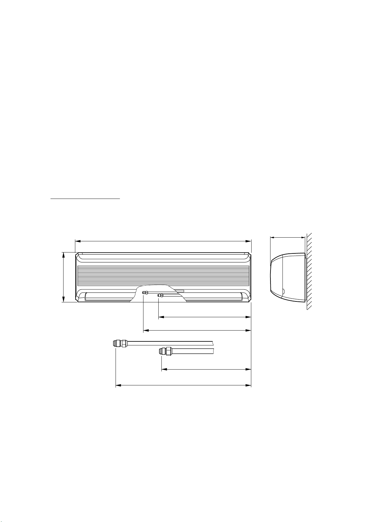
OUTLINE AND DIMENSIONS
Unit : mm
INDOOR UNIT
Models : ASG18FBAJ
ASG18FBBJ
ASG18FBBN
ASG18UBAJ
ASG18UBBJ
ASG18UBBN
ASG24FBBJ
ASG24FBBN
ASG24UBBJ
ASG24UBBN
ASG30FBBJ
ASG30UBBJ
1,120
321
626
711
626
711
224
2005.03.09
3
Page 5
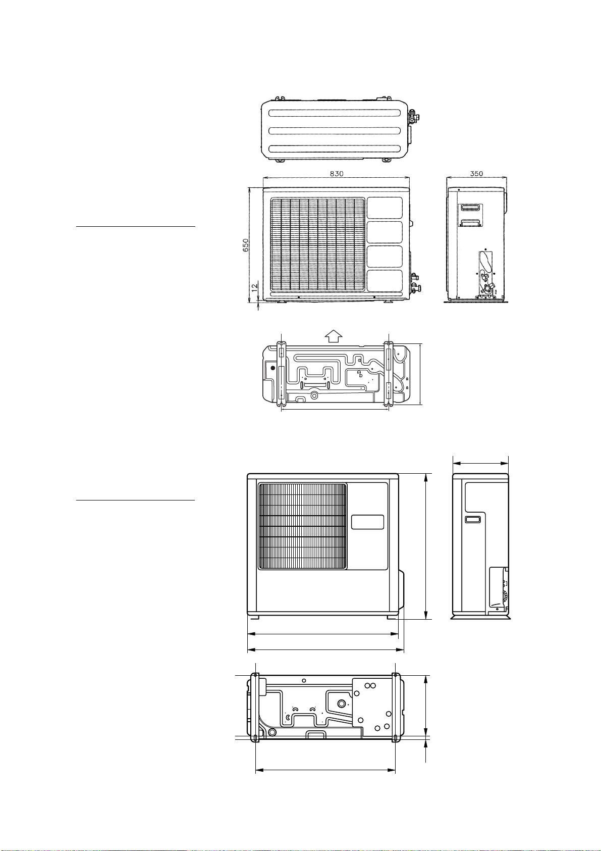
OUTDOOR UNIT
Unit : mm
Models : AOG18FNAK
AOG18FNBK
AOG18FNBN
AOG18UNAKL
AOG18UNBKL
AOG18UNBNL
AOG24FNBK
AOG24FNBN
AOG24UNBKL
AOG24UNBNL
Models : AOG30FNBDL
AOG30UNBDL
Bottom
Air flow
343
603
350
900
2005.03.09
900
930
333
19
804
4
Page 6
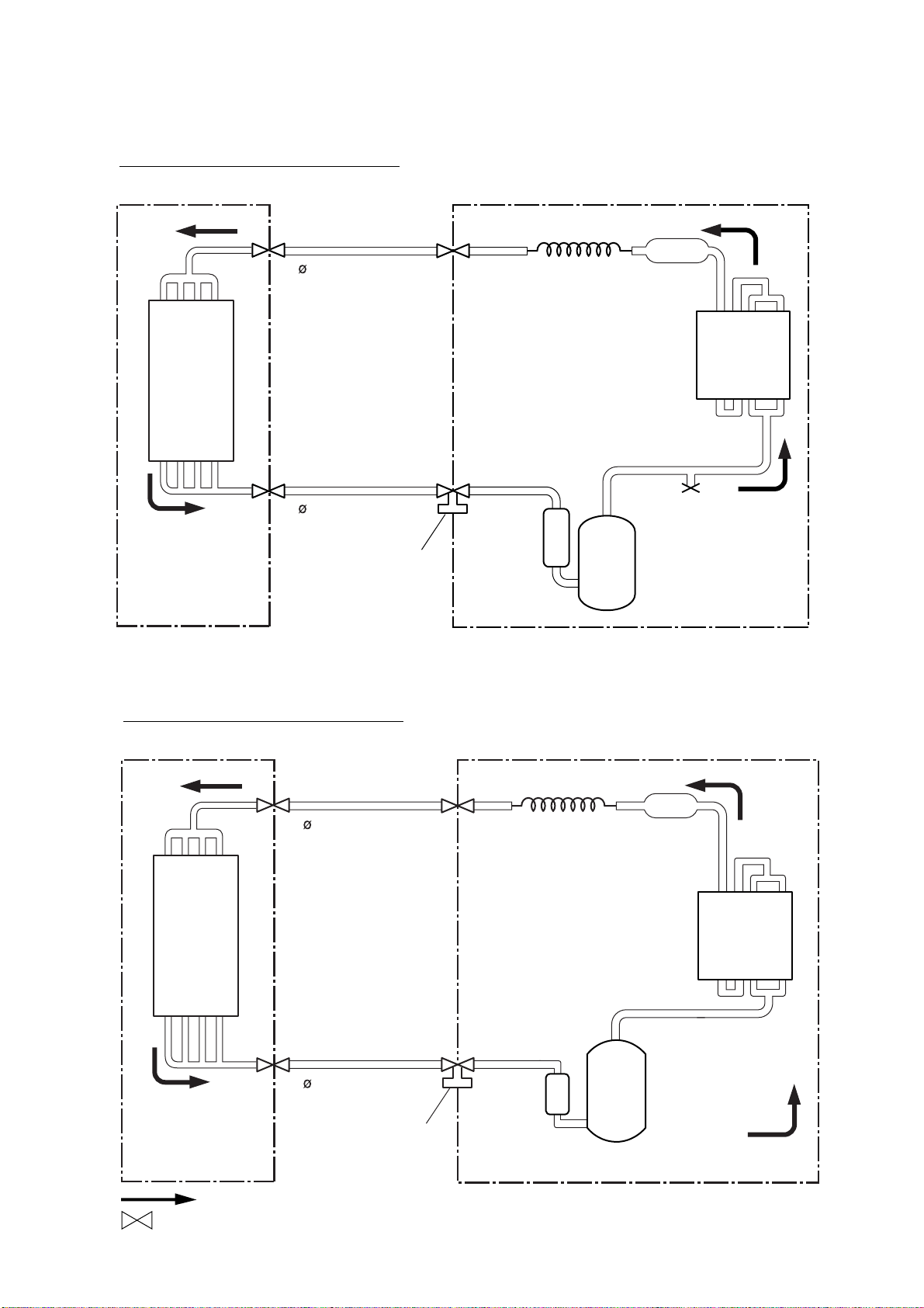
REFRIGERANT SYSTEM DIAGRAM
Models : ASG18FBAJ / AOG18FNAK
ASG18FBBJ / AOG18FNBK
ASG18FBBN / AOG18FNBN
INDOOR UNIT
Evaporator
Refrigerant pipe
6.35 mm (1/4")
Refrigerant pipe
15.88 mm (5/8")
Charging valve
OUTDOOR UNIT
Capillary tube
Strainer
Condenser
Compressor
Models : ASG24FBBJ / AOG24FNBK
ASG24FBBN / AOG24FNBN
INDOOR UNIT
Refrigerant pipe
9.52 mm (3/8")
Evaporator
Refrigerant pipe
15.88 mm (5/8")
Charging valve
OUTDOOR UNIT
Capillary tube
Compressor
Strainer
Condenser
Cooling
: Flare coupling
2005.03.09 5
Page 7
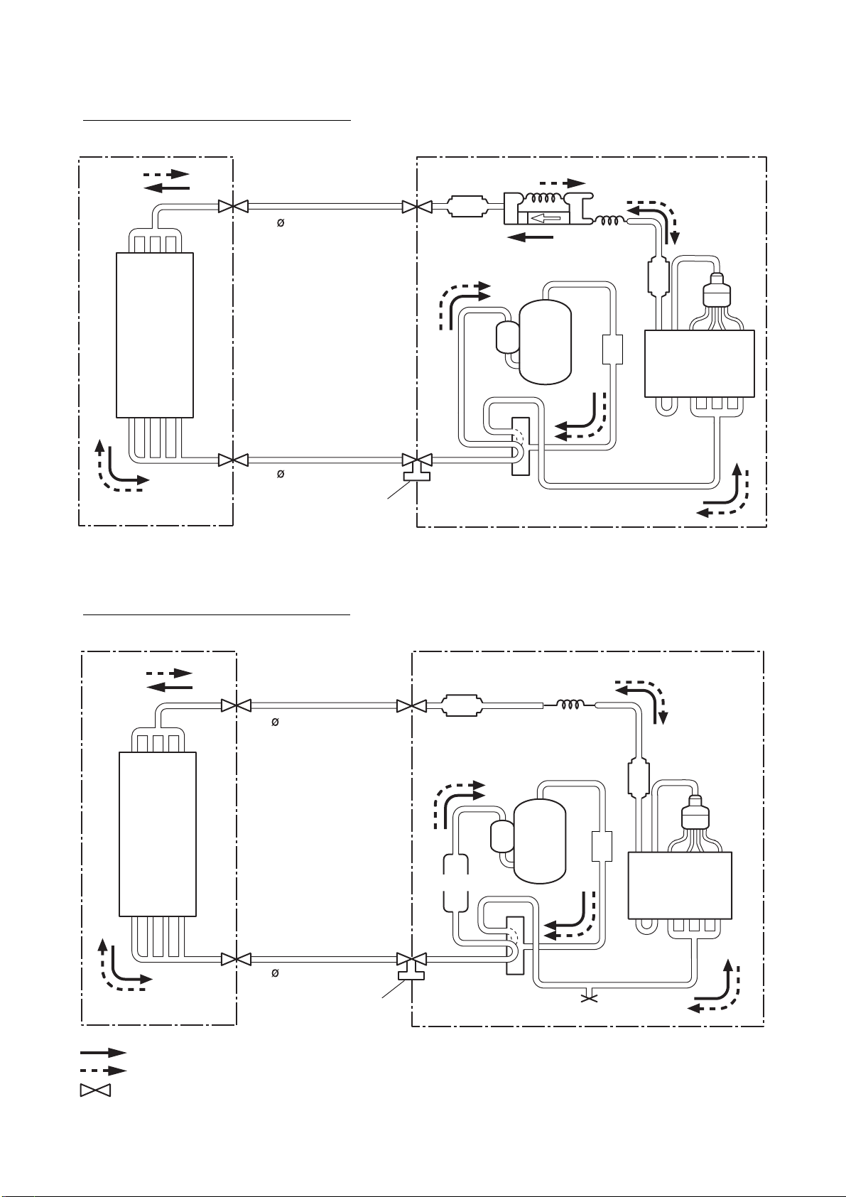
Models : ASG18UBAJ / AOG18UNAKL
ASG18UBBJ / AOG18UNBKL
ASG18UBBN / AOG18UNBNL
INDOOR UNIT
Evaporator
Refrigerant pipe
6.35mm(1/4")
Refrigerant pipe
15.88mm(5/8")
Charging valve
OUTDOOR UNIT
Strainer
Compressor
4-Way
valve
Capillary
tube
Muffler
Strainer
Condenser
Distributor
Models : ASG24UBBJ / AOG24UNBKL
ASG24UBBN / AOG24UNBNL
INDOOR UNIT
Refrigerant pipe
9.52mm(3/8")
Evaporator
Refrigerant pipe
15.88mm(5/8")
Charging valve
OUTDOOR UNIT
Strainer
Compressor
Accumulator
4-Way
valve
Capillary
tube
Strainer
Distributor
Muffler
Condenser
Cooling
Heating
: Flare coupling
2005.03.09 6
Page 8
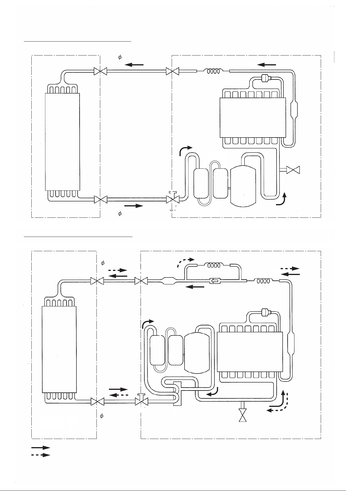
Models : ASG30FBBJ / AOG30FNBDL
INDOOR UNIT OUTDOOR UNIT
Evaporater
Refrigerant pipe
9.52mm(3/8")
Charging valve
Refrigerant pipe
15.88mm(5/8")
Cappillary tube
2-Way
valve
3-Way
valve
Distributor
Strainer
Condenser
PRESSURE
CHECK
VALVE
CondenserAccumulator
Models : ASG30UBBJ / AOG30UNBDL
INDOOR UNIT OUTDOOR UNIT
Refrigerant pipe
9.52mm(3/8")
Strainer
3-Way
valve
Evaporater
Accumulator
Charging valve
Cappillary tube
Compressor
Distributor
Strainer
Condenser
Refrigerant pipe
15.88mm(5/8")
3-Way
valve
4-Way valve
Cooling
Heating
2005.03.09 7
PRESSURE
CHECK
VALVE
Page 9
Controller PCB
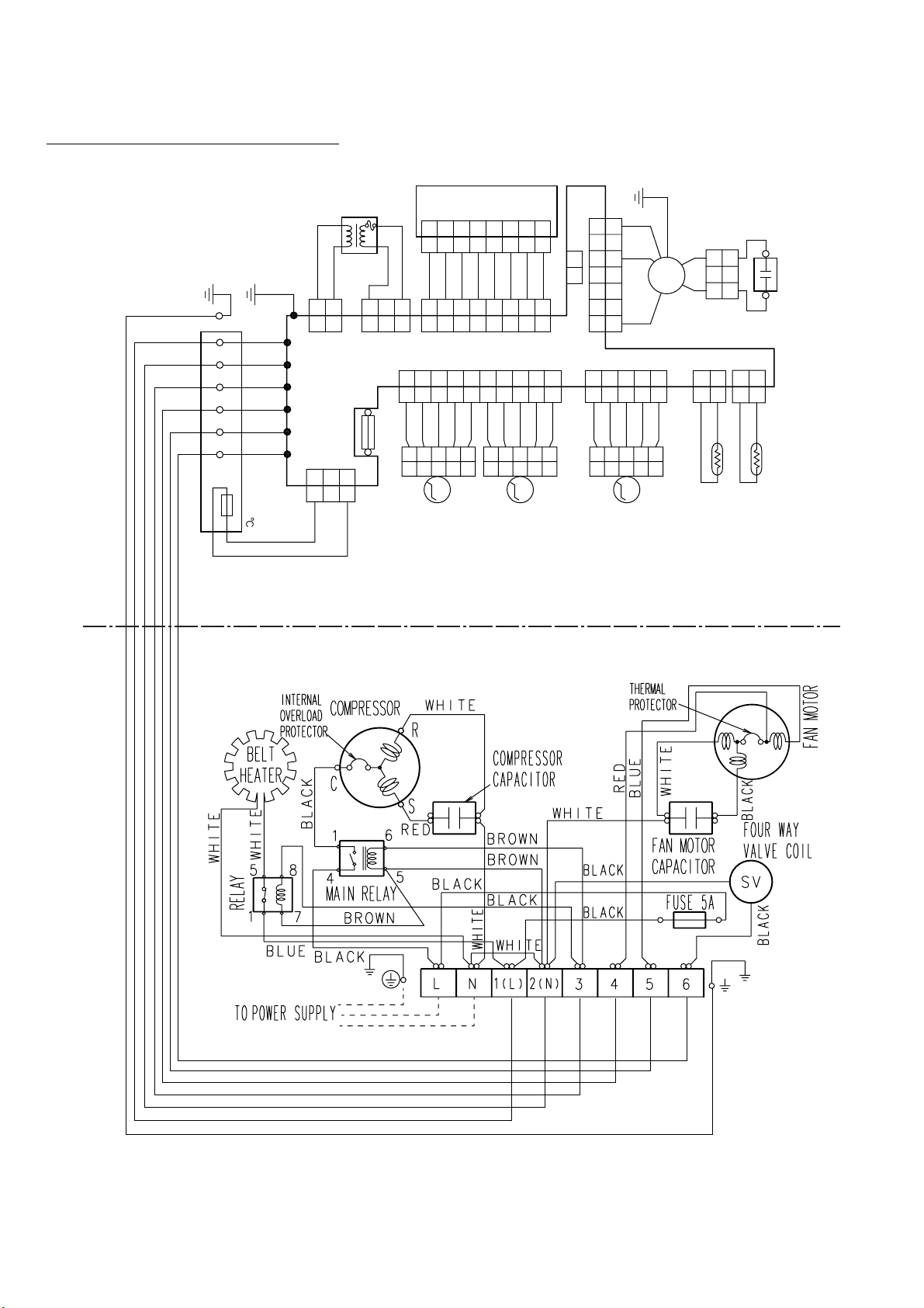
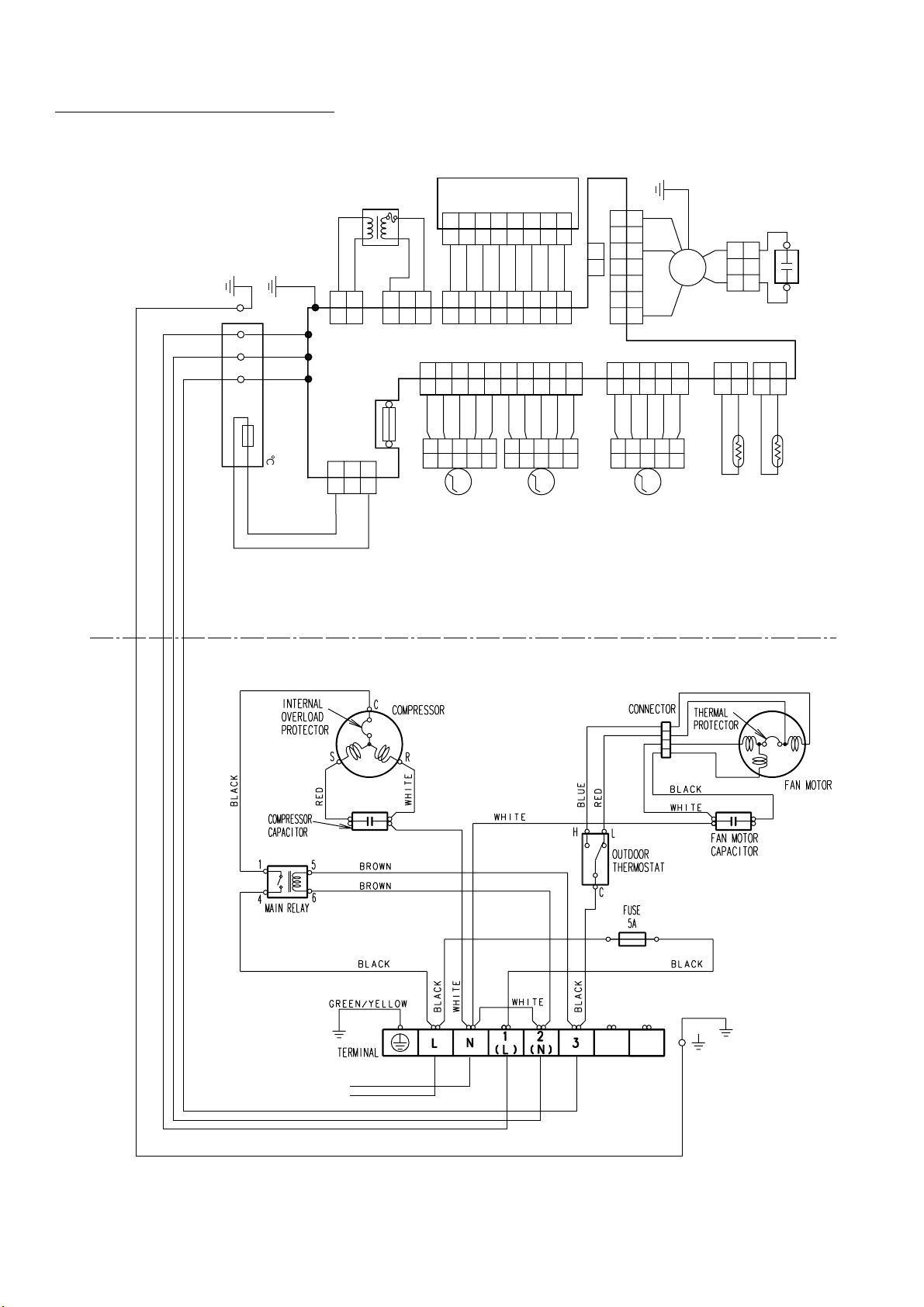
CIRCUIT DIAGRAM
Display Board
Fan Motor
Capacitor
GREEN/
YELLOW
CN4
CN201
Transformer
WHITE
BLUE
221
1
CN5
8
7
6
5
4
3
2
1
22113
3
YELLOW
RED
BLACK
FM
334455667
21
GRAY
8
GRAY
7
GRAY
6
GRAY
5
GRAY
4
GRAY
3
GRAY
2
PURPLE
1
PURPLE
PURPLE
RED
RED
WHITE
Fan
Motor
WHITE
7
8
8
7
7
6
6
5
5
4
4
3
3
2
2
1
1
3
3
2
2
1
1
2
2
1
1
GRAY
2
2
GRAY
1
1
CN11CN10CN7CN6
BLACK
2
2
BLACK
1
1
GRAY
5
5
GRAY
4
4
GRAY
3
3
GRAY
2
2
PINK
1
1
GRAY
10
10
GRAY
9
9
GRAY
8
8
GRAY
7
7
GRAY
6
6
GRAY
5
5
GRAY
4
4
GRAY
3
3
CN9CN2 CN1
L
N
GRAY
2
2
PINK
1
1
FUSE T 3. 15A 250V
Thermistor (Pipe temp.)
Thermistor (Room temp.)
5
5
4
4
Step Motor (Right / Left)
M
3
3
2
2
1
1
5
5
4
4
Step Motor (Up / Down)
M
3
3
2
2
1
1
5
5
4
4
3
3
Step Motor (Diffuser)
M
2
2
1
1
3
3
2
2
CN3
1
1
INDOOR UNIT
Models
: ASG18FBAJ / AOG18FNAK
ASG18FBBJ / AOG18FNBK
ASG18FBBN / AOG18FNBN
ASG24FBBJ / AOG24FNBK
ASG24FBBN / AOG24FNBN
GRAY
GREEN
WHITE
BLACK
GRAY
THERMAL
FUSE 102
GRAY
123
(N)
Terminal
Internal
Overload
Protector
Compressor
Main Relay
OUTDOOR UNIT
White
Compressor
Capacitor
White
White
Fuse 5A
Black
Black
Fan Motor
Thermal
Protector
Black
Fan Motor
Capacitor
to Power Supply
2005.03.09 8
Black
White
Page 10
(PIPE TEMP.)
GRAY
GRAY
WHITE
BROWN
GREEN
GRAY
GRAY
GRAY
FM
(ROOM TEMP.)
(RIGHT/ LEFT)
(UP/DOWN)
BLACK
BLACK
WHITE
WHITE
WHITE
BLACK
BLUE
RED
BLUE
RED
RED
BLACK
GRAY
GRAY
GRAY
GRAY
YELLOW
PINK
GRAY
GRAY
GRAY
GRAY
GRAY
GRAY
GRAY
PURPLE
PURPLE
PURPLE
GRAY
GRAY
GRAY
GRAY
GRAY
(DIFFUSER)
GRAY
GRAY
GRAY
GRAY
RED
PINK
M
M
M
GREEN/
YELLOW
L
N
FAN MOTOR
CAPACITOR
THERMISTOR
FAN
MOTOR
TERMINAL
THERMISTOR
STEP
MOTOR
STEP
MOTOR
STEP
MOTOR
TRANSFORMER
CONTROL BOARD
DISPLAY BOARD
CN4
CN5
CN11CN10CN7CN6
CN3
CN9CN2 CN1
CN201
THERMAL
FUSE 102
2
2
1
1
21
3
3
4
4
5
5
6
6
7
7
2
2
1
1
3
3
22113
3
221
1
776
6
221133445
5
7
7
8
8
8
8
6
6
221133445
5
22113
3
221133445
5
221
1
889910
10
776
6
221133445
5
221
1
221133445
5
221133445
5
221133445
5
(N)
123
FUSE T 3. 15A 250V
456
OUTDOOR UNIT
INDOOR UNIT
Models : ASG18UBAJ / AOG18UNAKL
2005.03.09 9
Page 11
Controller PCB
Fan Motor
GREEN/
YELLOW
CN4
DISPLAY BOARD
CN201
Transformer
WHITE
Capacitor
BLUE
221
1
CN5
8
7
6
5
4
3
2
1
22113
3
YELLOW
RED
BLACK
FM
334455667
21
GRAY
8
GRAY
7
GRAY
6
GRAY
5
GRAY
4
GRAY
3
GRAY
2
PURPLE
1
PURPLE
PURPLE
RED
RED
WHITE
Fan
Motor
WHITE
7
8
7
6
5
4
3
2
1
3
2
1
2
1
GRAY
2
2
GRAY
CN11CN10CN7CN6
1
1
BLACK
2
2
BLACK
1
1
Thermistor (Pipe temp.)
Thermistor (Room temp.)
Models : ASG18UBBJ / AOG18UNBKL
ASG18UBBN / AOG18UNBNL
ASG24UBBJ / AOG24UNBKL
ASG24UBBN / AOG24UNBNL
GRAY
5
5
GRAY
4
4
GRAY
3
3
GRAY
2
2
PINK
1
1
GRAY
10
8
7
6
5
4
3
2
1
CN9CN2 CN1
3
2
10
GRAY
9
9
GRAY
8
8
GRAY
7
7
GRAY
6
6
GRAY
5
5
GRAY
4
4
GRAY
3
3
GRAY
2
2
PINK
1
1
FUSE T 3. 15A 250V
5
5
4
4
Step Motor (Right / Left)
M
3
3
2
2
1
1
5
5
4
4
M
3
2
1
5
4
3
2
1
Step Motor (Up / Down)
3
2
1
5
4
Step Motor (Diffuser)
3
M
2
1
1
3
2
1
L
N
3
2
2
CN3
1
1
INDOOR UNIT
GRAY
GREEN
WHITE
BLACK
GRAY
123
BLUE
456
THERMAL
FUSE 102
BROWN
RED
GRAY
(N)
Terminal
OUTDOOR UNIT
Internal
Overload
Protector
Compressor
Black
Main Relay
Black
Red
Black
White
Compressor
Capacitor
Brown
Fuse 5A
Brown
White
Black
White
White
Black
Thermal
Protector
Red
White
Fan Motor
Capacitor
Fan Motor
Black
Blue
4-way
Valve Coil
Black
2005.03.09
to Power Supply
10
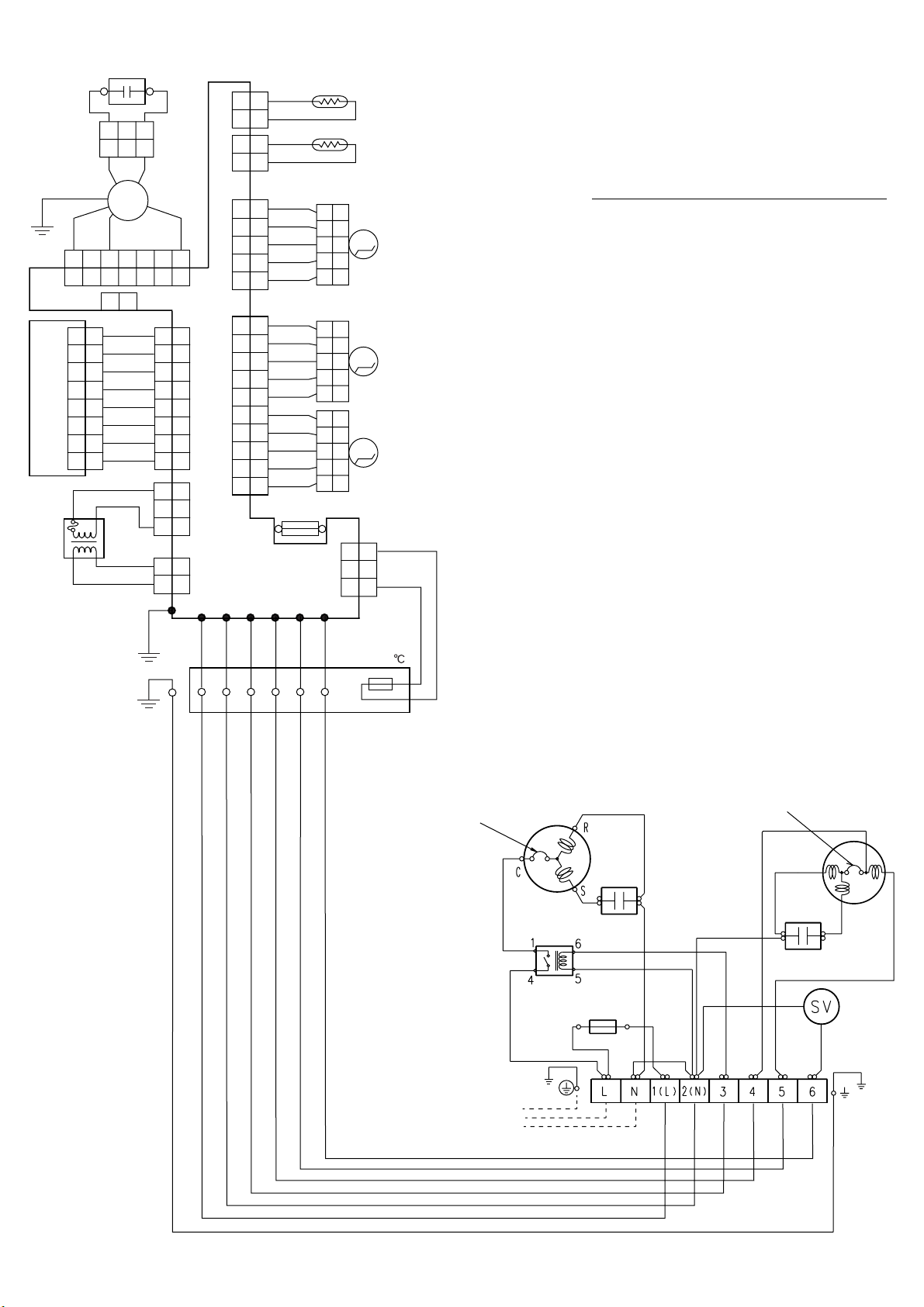
Page 12
Model : ASG30FBBJ / AOG30FNBDL
TRANSFORMER
RED
RED
GREEN
221
BLACK
123
WHITE
(N)
GRAY
THERMAL
TERMINAL
FUSE 102
1
L
N
CN3
22113
FUSE T 3. 15A 250V
22113
3
GRAY
GRAY
DISPLAY BOARD
CN201
221133445
PURPLE
PURPLE
PURPLE
GRAY
221133445
3
CN9CN2 CN1
221133445
GRAY
GRAY
PINK
221133445
M
(DIFFUSER)
STEP
MOTOR
7
8
6
7
8
6
5
GRAY
GRAY
GRAY
GRAY
GRAY
5
GRAY
776
8
6
8
CONTROL BOARD
889910
776
6
5
GRAY
GRAY
GRAY
10
GRAY
GRAY
GRAY
221133445
5
5
M
(UP/DOWN)
STEP
MOTOR
CN4
1
1
CN5
21
BLUE
2
2
RED
3
3
4
4
5
5
6
6
WHITE
7
7
221133445
GRAY
GRAY
PINK
GRAY
221133445
M
(RIGHT/ LEFT)
STEP
MOTOR
GREEN/
YELLOW
FAN MOTOR
CAPACITOR
WHITE
YELLOW
FM
FAN
MOTOR
BLACK
5
GRAY
GRAY
1
1
2
2
3
3
WHITE
CN11CN10CN7CN6
221
221
1
1
GRAY
BLACK
GRAY
BLACK
5
(PIPE TEMP.)
(ROOM TEMP.)
THERMISTOR
THERMISTOR
INDOOR UNIT
OUTDOOR UNIT
TO POWER SOURCE
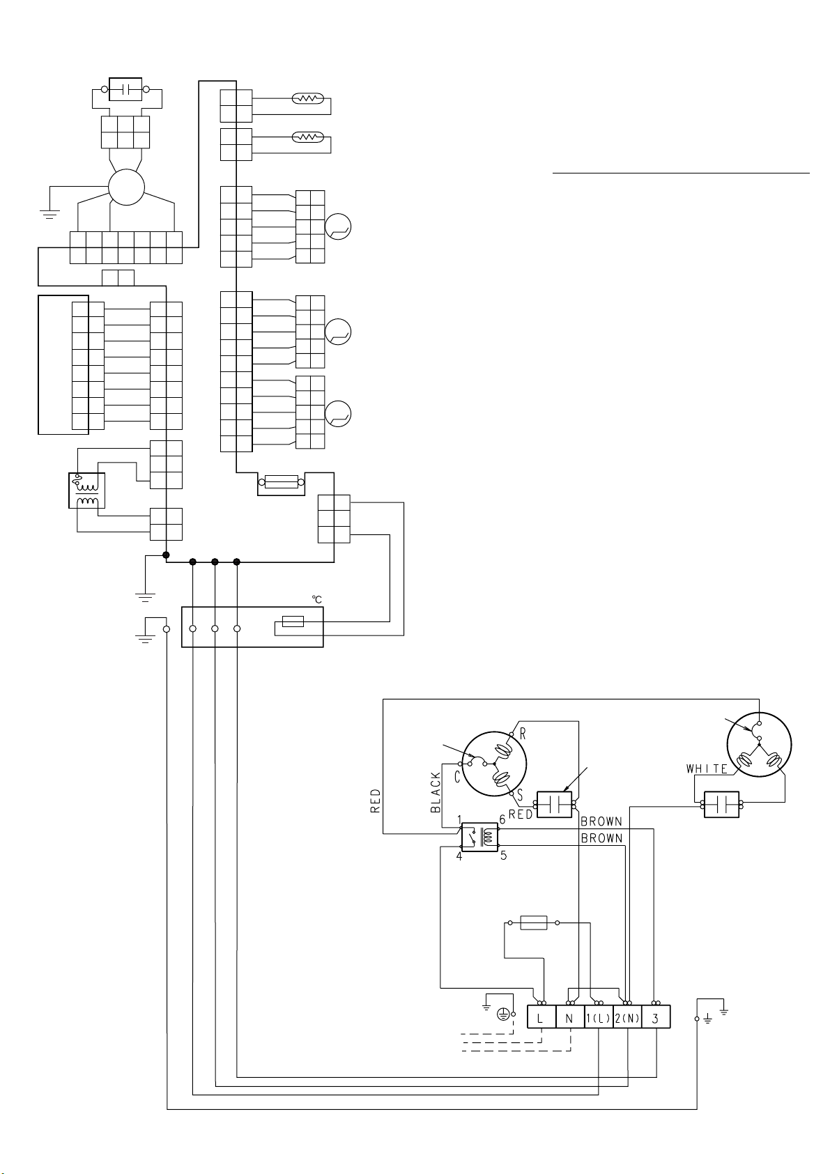
2005.03.09 11
Page 13

(PIPE TEMP.)
GRAY
GRAY
WHITE
BROWN
GREEN
GRAY
GRAY
GRAY
FM
(ROOM TEMP.)
(RIGHT/ LEFT)
(UP/DOWN)
BLACK
BLACK
WHITE
WHITE
WHITE
BLACK
BLUE
RED
BLUE
RED
RED
BLACK
GRAY
GRAY
GRAY
GRAY
YELLOW
PINK
GRAY
GRAY
GRAY
GRAY
GRAY
GRAY
GRAY
PURPLE
PURPLE
PURPLE
GRAY
GRAY
GRAY
GRAY
GRAY
(DIFFUSER)
GRAY
GRAY
GRAY
GRAY
RED
PINK
M
M
M
GREEN/
YELLOW
L
N
C
RS
BLACK
BLACK
BLACK
BLUE
RED
SV
BLACK BLACK
RED
BLACK
BLACK
BROWN
BROWN
WHITE
WHITE
WHITE
WHITE
WHITE
6
5
4
1
FAN
MOTOR
FUSE
5A
TERMINAL
FAN MOTOR
CAPACITOR
COMPRESSOR
CAPACITOR
COMPRESSOR
MAIN
RELAY
FAN MOTOR
CAPACITOR
THERMISTOR
FAN
MOTOR
TERMINAL
THERMISTOR
STEP
MOTOR
STEP
MOTOR
STEP
MOTOR
TRANSFORMER
CONTROL BOARD
DISPLAY BOARD
CN4
CN5
CN11CN10CN7CN6
CN3
CN9CN2 CN1
CN201
THERMAL
FUSE 102
(L) (N)
LN 312
THERMAL
PROTECTOR
INTERNAL
OVERLOAD
PROTECTOR
2
2
1
1
21
3
3
4
4
5
5
6
6
7
7
2
2
1
1
3
3
22113
3
221
1
776
6
221133445
5
7
7
8
8
8
8
6
6
221133445
5
22113
3
221133445
5
221
1
889910
10
776
6
221133445
5
221
1
221133445
5
221133445
5
221133445
5
(N)
123
FUSE T 3. 15A 250V
4-WAY
VALVE COIL
456
456
CONNECTOR
OUTDOOR UNIT
INDOOR UNIT
TO POWER SOURCE
Models : ASG30UBBJ / AOG30UNBDL
2005.03.09 12
Page 14

ERROR DISPLAY
The OPERATION, TIMER and SWING lamps operate as follows according to the error contents.
Fast flashing
:
Slow flashing
:
Error contents
Indoor unit circuit board error
Indoor unit room temperature sensor wire
opened
Indoor unit room temperature sensor wire
short circuited
Indoor unit piping sensor wire opened
Indoor unit piping sensor wire short circuited
Off
:
Error display
OPERATION TIMER SWING
(RED) (GREEN) (ORANGE)
2 times
2 times
3 times
3 times
Indoor unit fan error
6 times
2005.03.09 13
Page 15

INDOOR PCB CIRCUIT DIAGRAM
Models :
ASG18FBAJ
ASG18FBBJ
ASG18FBBN
ASG24FBBJ
ASG24FBBN
ASG30FBBJ
CONTROLLER PCB ASSEMBLY ( MAIN PCB )
ASY18FBAJ : EZ-003HWSE-C
ASY18FBBJ, ASY18FBBN : EZ-001TWSE-C
ASY24FBBJ, ASY24FBBN : EZ-003KWSE-C
ASY30FBBJ : EZ-001SWSE-C
THRMAL FUSE
GRAY
GRAY
RED
RED
CN2
B2B-XARK-1-A
UL1430 AWG22
UL1430 AWG22
SECONDARY
POWER
TRANSFORMER
EZ-0018HSE-T
PRIMARY
OUTDOOR UNIT
1
2
3
TERMINAL
BOARD
2005.03.09 15
CN3 B3B-XASK-1-A
3-3
3-1
2-1
2-2
BLACK
YELLOW
3 1
WHITE
UL1015
AWG20
D1
D2SB20
+
R1 10K
C7
<1/2W>
2200
/50V
UL1015
AWG20
RED
FAN
MOTOR
FAN CAPACITOR
WHITE
1.3 uF
BLUE
RED
WHITE
UL1015 AWG22 PURPLE
UL1015 AWG22 PURPLE
GRAYUL1015 AWG22
UL1015
AWG16
GREEN
UL1015
AWG14
WHITE
E1
SA1
RA-362M
W2
N
UL1015
AWG14
BLACK
W1
FH1
L
3.15A
<BET>
F1
D4 D1F60
CN4
B4P7S-VH-B
CN1
B2P3-VH-B
COMP
VA2
470V
<TNR>
FH2
R2 10K
<1/4W>
+
C8
10/25V
4-1
4-2
4-3
4-4
1-3
1-1
W6
Q1
2SD1191
C9
10/
25V
14V
+
D3
D1F60
C10
1000
/25V
+
IC2
7805
I O
G
5V
C11
0.1
<F>
D2
MTZJ15C
R3
1.0K <1/10W>
C12
0.1
<F>
Q2
DTC124EUA
K1
JQ1-12V
R4 4.7K
<1/10W>
SSR1
G3MC
14V
+
VA3
470V <TNR>
-
201PL-VD
14V
K 5
R12
C22
0.1
<F>
JM3
JM2
JM1
1.0K x 3
<1/10W>
JM6
JM5
JM4
5V
8
7
6
5
10K <1/10W>
VCC
NC
NC
GND
IC3
BR93LC46
5V
R23
R22
5V
R16
R17
K5
G5NB-1A
C2
0.22 <RE>
C6
C5
0.022 x 2
<YE>
LF1
ELF17N015A
C1
0.22 <RE>
VA1
470V <TNR>
JM1 : FAN CHANGER
JM2 : REMOTE CONTROL CUSTOM CODE 1
JM3 : REMOTE CONTROL CUSTOM CODE 2
JM4 : AUTO RESTART
JM5 : HEATING TEMPERATURE CORRECTION
JM6 : HEATING TEMPERATURE CORRECTION
C14
100
/25V
5V
K 1
D0
D1
SK
CS
10K x 3
<1/10W>
R24
1.0K x 3
<1/10W>
R18
1.0K x 3
<1/10W>
C15
+
0.1
<F>
R5
10K
<1/10W>
C13
1000P
<R>
15
16
13
12
14
D6
DA226U
4
3
2
1
RC2
R21
R20
R19
R15
R14
R13
IC5 (5/7)
uPA2003
Q3
2SC982
R6
10K
<1/10W>
RC3
RC4
1000P x 4
<R>
C28
0.01 x 3
<B>
C24
C25
0.01 x 3
<B>
R45
R46
10K x 2
<1/10W>
NC
NC
2
1
4
5
3
R7
10K
<1/10W>
C21
C26
C27
C23
74
68
75
73
78
80
64
51
52
22
23
19
20
10
11
12
13
56
57
58
53
54
55
67
33
61
7
I C 1
uPD780058
(uPD78F0058)
-A14-9EU
8
9
4
69
X1
5.00MHz
<CSTS>
5V
10K x 2
R39
R40
Q5
C29
0.1
<F>
C30
0.1
<F>
IC7 (4/7)
uPA2003
10K x 4
<1/10W>
R35
1.0K x 4
<1/10W>
R43 1.0K
<1/10W>
C17
0.1 <F>
<1/10W>
Q4
DTA143
C42
+
10/
25V
CN9
S08B-PASK-2
5V
CN10
B2B-XASK-1-A
CN11
B2B-XAKK-1-A
14V
CN6
S10B-PASK-2
14V
11
12
13
14
CN7
S05B-PASK-2
5V
CN13
BS5P-SHF-1AA
R38
R36
R37
R44 1.0K
<1/10W>
B Z
BZ1
PKM13EPY-4000-TF01
C41
0.01
<F>
13-1
13-2
13-3
13-4
13-5
14V
9-8
9-7
9-6
9-5
9-4
9-3
9-2
9-1
10-1
10-2
11-1
11-2
6-1
6-2
6-3
6-4
6-5
6-6
6-7
6-8
6-9
6-10
7-1
7-2
7-3
7-4
7-5
R41 1.0K <1/10W>
59
63
C35
1000P <R>
49
47
46
45
R42 47 <1/10W>
C36
0.01 <B>
Q7
Q6
DTC124EUA x 3
R27
C33
1000P
<R>
C34
1000P
<R>
1.0K <1/10W>
R28
1.0K <1/10W>
IC6 (7/7)
uPA2003
7
6
5
4
3
2
1
7
R25
10K
<1/10W>
(1%)
R26
49.9K
<1/10W>
(1%)
10
11
12
13
14
15
16
10
76
77
27
28
29
30
31
32
34
35
IC7 (1/7)
uPA2003
40
41
42
43
71
65
RC1
10K
R11
6
5
4
3
<1/10W>
17
16
15
14
C38
C37
0.01 x 4
R31
R32
R33
R34
C40
C39
<B>
50
1 16
IC7-1
uPA2003
5V
R8 10K
<1/10W>
60
C16
70
0.1 <F>
IC4
PST600C
5V
O
I
G
UL1430
AWG26
GRAY
GRAY
GRAY
GRAY
GRAY
GRAY
GRAY
PURPLE
201-8
201-7
D202
SLR-325 <RED>
201-6
201-5
201-4
201-3
201-2
C202
10/
25V
201-1
SW201
EVQ-PAG-04K
R204
R203
R201
5V
C201
+
0.1
<F>
R202
330 x 4 <1/4W>
INDICATOR PCB
EZ-0018HSE-D
D204 <ORG>
D203 <GRN>
D201 <ORG>
SLR-325 x 3
5V
C203
0.01
<F>
PHA201
SBX1810
VCC
OUT
GND1
GND2
CN201 S08B-PASK-2
BLACK
BLACK
GRAY
GRAY
ROOM TEMPERATURE THERMISTOR
PIPE TEMPERATURE THERMISTOR
UL1061
AWG26
PINK
GRAY
GRAY
DIFFUSER
GRAY
GRAY
GRAY
GRAY
FLAP
GRAY
U - D
GRAY
GRAY
UL1061
AWG26
PINK
GRAY
LOUVER
GRAY
L - R
GRAY
GRAY
TEST
Jumper wire configurations
Switch Function ON/Linked OFF/Open
JM1 High ceiling
JM2 / JM3 Custom code
JM4 Auto restart enable disable
JM5 / JM6
Heating compensation
Table 1 Table 2
standard
(See table 2)
(See table 1)
High Ceiling 1
ON / ON +4 ON / ON A
ON / OFF -2 ON / OFF B
OFF / ON 0 OFF / ON C
OFF / OFF +2 OFF / OFF D
Page 16

Models : ASG18UBAJ
ASG18UBBJ
ASG18UBBN
ASG24UBBJ
ASG24UBBN
ASG30UBBJ
CONTROLLER PCB ASSEMBLY ( MAIN PCB )
ASY18UBAJ : EZ-003WHSE-C
ASY18UBBJ, ASY18UBBN : EZ-0034HSE-C
ASY24UBBJ, ASY24UBBN : EZ-003YHSE-C
THRMAL FUSE
GRAY
GRAY
RED
RED
CN2
B2B-XARK-1-A
UL1430 AWG22
UL1430 AWG22
SECONDARY
POWER
TRANSFORMER
EZ-0018HSE-T
PRIMARY
OUTDOOR UNIT
1
2
3
4
5
6
TERMINAL
BOARD
2005.03.09 16
CN3 B3B-XASK-1-A
3-3
3-1
2-1
2-2
BLACK
3 1
WHITE
UL1015
AWG20
UL1015
AWG22
UL1015
AWG22
D1
D2SB20
+
C7
2200
/50V
FAN
MOTOR
YELLOW
FAN CAPACITOR
WHITE
1.3 uF
UL1015 AWG22 PURPLE
UL1015 AWG22 PURPLE
UL1015
AWG16
GREEN
E1
UL1015
AWG14
WHITE
W2
N
UL1015
AWG14
BLACK
W1
L
UL1015
AWG22
BROWN
RED
BLUE
W5
W3
W4
LO
4WV
H I
K3
JQ1-12V
R1 10K
<1/2W>
UL1015
AWG20
RED
BLUE
RED
WHITE
SA1
RA-362M
FH1
<BET>
GRAYUL1015 AWG22
FH2
F1
3.15A
K4
G5NB-1A
CR2
120/0.2
K2
G5NB-1A
CR2
120/0.2
R2 10K
<1/4W>
+
C8
10/25V
D4 D1F60
CN4
B4P7S-VH-B
4-1
4-2
4-3
4-4
1-3
1-1
CN1
B2P3-VH-B
COMP
W6
VA2
470V
<TNR>
14V
C10
1000
/25V
IC2
7805
I O
G
C11
+
0.1
<F>
Q1
2SD1191
C9
10/
25V
D3
D1F60
+
D2
MTZJ15C
R3
1.0K <1/10W>
C12
0.1
<F>
Q2
DTC124EUA
K1
JQ1-12V
R4 4.7K
<1/10W>
SSR1
G3MC
14V
+
VA3
470V <TNR>
-
201PL-VD
14V
K 5
R12
C22
0.1
<F>
JM3
JM2
JM1
1.0K x 3
<1/10W>
JM6
JM5
JM4
5V
8
7
6
5
10K <1/10W>
VCC
NC
NC
GND
IC3
BR93LC46
5V
R22
5V
R16
K5
G5NB-1A
C2
0.22 <RE>
C6
C5
0.022 x 2
<YE>
LF1
ELF17N015A
C1
0.22 <RE>
VA1
470V <TNR>
JM1 : FAN SWITCHING
JM2 : CUSTOM CODE SWITCHING-1
JM3 : CUSTOM CODE SWITCHING-2
JM4 : AUTO RESTART SWITCHING
JM5 : ROOM TEMPERATURE CORRECTION
( HEATING OPERATION )
JM6 : ROOM TEMPERATURE CORRECTION
( HEATING OPERATION )
5V
R23
R17
1.0K x 3
<1/10W>
ASY30UBBJ : EZ-0010CHSE-C
C15
C14
+
0.1
100
<F>
/25V
R45
IC5 (5/7)
uPA2003
Q3
2SC982
R6
10K
<1/10W>
RC3
RC4
C28
0.01 x 3
<B>
C25
0.01 x 3
<B>
R46
10K x 2
<1/10W>
NC
NC
2
1
4
5
3
R7
10K
<1/10W>
C21
C26
C27
C23
C24
5V
K 1
K 2
K 3
K 4
D0
D1
SK
CS
10K x 3
<1/10W>
R24
1.0K x 3
<1/10W>
R18
R5
10K
<1/10W>
C13
1000P
<R>
15
16
13
12
14
D6
DA226U
4
3
2
1
RC2
1000P x 4
<R>
R21
R20
R19
R15
R14
R13
74
68
75
7
73
78
80
uPD780058
64
(uPD78F0058)
-A14-9EU
8
9
51
52
22
23
19
20
10
11
12
13
56
57
58
53
54
55
4
67
33
61
69
X1
5.00MHz
<CSTS>
I C 1
5V
10K x 2
R39
R40
Q5
C29
0.1
<F>
C30
0.1
<F>
IC7 (4/7)
uPA2003
10K x 4
<1/10W>
R35
1.0K x 4
<1/10W>
R43 1.0K
<1/10W>
C17
0.1 <F>
<1/10W>
Q4
DTA143
C42
+
10/
25V
CN9
S08B-PASK-2
5V
CN10
B2B-XASK-1-A
CN11
B2B-XAKK-1-A
14V
CN6
S10B-PASK-2
14V
11
12
13
14
CN7
S05B-PASK-2
5V
CN13
BS5P-SHF-1AA
R38
R36
R37
R44 1.0K
<1/10W>
B Z
BZ1
PKM13EPY-4000-TF01
C41
0.01
<F>
13-1
13-2
13-3
13-4
13-5
14V
9-8
9-7
9-6
9-5
9-4
9-3
9-2
9-1
10-1
10-2
11-1
11-2
6-1
6-2
6-3
6-4
6-5
6-6
6-7
6-8
6-9
6-10
7-1
7-2
7-3
7-4
7-5
R41 1.0K <1/10W>
59
63
C35
1000P <R>
49
47
46
45
R42 47 <1/10W>
C36
0.01 <B>
Q7
Q6
DTC124EUA x 3
R27
C33
1000P
<R>
C34
1000P
<R>
1.0K <1/10W>
R28
1.0K <1/10W>
IC6 (7/7)
uPA2003
7
6
5
4
3
2
1
7
R25
10K
<1/10W>
(1%)
R26
49.9K
<1/10W>
(1%)
10
11
12
13
14
15
16
10
76
77
27
28
29
30
31
32
34
35
IC7 (1/7)
uPA2003
40
41
42
43
71
65
RC1
10K
R11
6
5
4
3
<1/10W>
17
16
15
14
C38
C37
0.01 x 4
R31
R32
R33
R34
C40
C39
<B>
50
1 16
IC7-1
uPA2003
5V
R8 10K
<1/10W>
60
C16
70
0.1 <F>
IC4
PST600C
5V
O
I
G
UL1430
AWG26
GRAY
GRAY
GRAY
GRAY
GRAY
GRAY
GRAY
PURPLE
201-8
201-7
D202
SLR-325 <RED>
201-6
201-5
201-4
201-3
201-2
C202
10/
25V
201-1
SW201
EVQ-PAG-04K
R204
R203
R201
5V
C201
+
0.1
<F>
R202
330 x 4 <1/4W>
INDICATOR PCB
EZ-0018HSE-D
D204 <ORG>
D203 <GRN>
D201 <ORG>
SLR-325 x 3
5V
C203
0.01
<F>
PHA201
SBX1810
VCC
OUT
GND1
GND2
CN201 S08B-PASK-2
BLACK
BLACK
GRAY
GRAY
ROOM TEMPERATURE THERMISTOR
PIPE TEMPERATURE THERMISTOR
UL1061
AWG26
PINK
GRAY
GRAY
DIFFUSER
GRAY
GRAY
GRAY
GRAY
FLAP
GRAY
U - D
GRAY
GRAY
UL1061
AWG26
PINK
GRAY
LOUVER
GRAY
L - R
GRAY
GRAY
TEST
Jumper wire configurations
Switch Function ON/Linked OFF/Open
JM1 High ceiling
JM2 / JM3 Custom code
standard
(See table 2)
JM4 Auto restart enable disable
JM5 / JM6
Heating compensation
(See table 1)
High Ceiling 1
Table 1 Table 2
ON / ON +4 ON / ON A
ON / OFF -2 ON / OFF B
OFF / ON 0 OFF / ON C
OFF / OFF +2 OFF / OFF D
Page 17

DISASSEMBLY ILLUSTRATION
61
Models : ASG18FBAJ
ASG18FBBJ
ASG18FBBN
ASG18UBAJ
ASG18UBBJ
ASG18UBBN
ASG24FBBJ
ASG24FBBN
ASG24UBBJ
ASG24UBBN
815
963-1
574-2
169
45
63
122
963
428
108
321
74
707
69-1
69
506
385
338-2
146
69-2
855-1
163-2
998
160-1
338
759
473-1
564-2
855
473
942
999
855-2
178-1
233
329
425
764
735
574-1
164
34
846
236
938
151
160
127
158
40
338-1
178-1
199
557
960
401
2005.03.09 17
199
743
240
Page 18

61
Models : ASG30FBBJ
ASG30UBBJ
588
574-2
45
122
63
428
74
146-2
160-1
169
707
220
146-1
759
163-2
329
564
942
473-1
999
233
735
815
425
764
34
236
938
514
160
127
158
963-1
557
963
108
69-1
321
69
960
401
385
338-2
69-2
855-1
506
338
855
473
855-2
178-1
240
40
574-1
338-1
164
178-1
199
199
743
2005.03.09 18
Page 19

Models : ASG18FBAJ
ASG18FBBJ
ASG18FBBN
ASG18UBAJ
ASG18UBBJ
ASG18UBBN
ASG24FBBJ
ASG24FBBN
ASG24UBBJ
ASG24UBBN
ASG30FBBJ
ASG30UBBJ
506
69-2
x 3
69-1
x 10
69
2005.03.09 19
Page 20

199
684
522-2
Models:ASG18FBAJ
ASG18FBBJ
ASG18FBBN
ASG18UBAJ
ASG18UBBJ
ASG18UBBN
ASG24FBBJ
ASG24FBBN
ASG24UBBJ
ASG24UBBN
ASG30FBBJ
ASG30UBBJ
522-3
408
522-1
199
435
92
2005.03.09 20
Page 21

Models :
AOG18FNAK
AOG18FNBK
AOG18FNBN
AOG24FNBK
AOG24FNBN
AOG18UNAKL
AOG18UNBKL
AOG18UNBNL
AOG24UNBKL
AOG24UNBNL
2005.03.09 21
Page 22

Models :
AOG30FNBD
AOG30UNBDL
527
407
84
373
9
734
64
477
5
2
4
2005.03.09 22
Page 23

Models :
AOG30FNBDL
AOG30UNBDL
26
32
85
55
16
817
983
29
45-1
45-2
45-3
109
754
51
55
412
107
46
45-4
117-3
12
328
117-3
41
2005.03.09 23
39
Page 24

Model : AOG18UNAKL
Models : AOG18FNAK
AOG18FNBK
AOG18FNBN
AOG18UNBKL
AOG18UNBNL
AOG24FNBK
AOG24FNBN
AOG24UNBKL
AOG24UNBNL
AOG30FNBDL
AOG30UNBDL
412
51
754
109
46
754
51
109
8
412
55
55
46
413
107
2005.03.09 24
107
Page 25

Models : AOG18FNAK
AOG18FNBK
AOG18FNBN
AOG24FNBK
AOG24FNBN
34
218-3
824-4
823-2
187
815
989-1
Model : AOG18UNAKL
34
38
38
37
218-3
218-4
824-4
989-2
32
823-2
187
815-3
989-1
989-2
37
Model : AOG18UNBKL
AOG18UNBNL
218-3
AOG24UNBKL
AOG24UNBNL
34
38
37
2005.03.09 25
824-4
32
823-2
187
815-3
989-1
989-2
32
Page 26

Model : AOG30FNBDL
34
218-3
549
824-4
823-2
815-3
989-1
989-2
37
38
187
Model : AOG30UNBDL
218-3
823-2
32
824-4
815-3
989-2
989-1
34
2005.03.09 26
187
38
37
Page 27

Model : AOG18FNAK
17
47-1
348-1
Model : AOG18FNBK
AOG18FNBN
58-1
17
420
272
178-2
826
20
14
13
18
47-1
17
58-1
420
272
826
348-1
20
14
13
2005.03.09 27
Page 28

Models : AOG18UNAKL
AOG18UNBKL
AOG18UNBNL
58-1
271
330
344
18
772-4
772-3
272
178-2
772-2
348
Model : AOG24FNBK
AOG24FNBN
826-1
178-2
20-1
259
20-2
772-1
420
259
272
178-2
14
13
348-1
17
47-1
58-1
17
420
272
178-2
826
20
14
13
2005.03.09 28
Page 29

Model : AOG24UNBKL
AOG24UNBNL
330
867
58-1
333
58-2
271
20-1
259
20-2
344
18
58-3
772-1
178-2
420
259
14
13
272
272
772-2
178-2
348
826-1
2005.03.09 29
Page 30

Model : AOG30FNBDL
46
420
20
82-1
272
867
263
2005.03.09 30
13-2
13
Page 31

Model : AOG30UNBDL
344
343
342
263
272
13-2
13
82-1
772
867
735
46
420
272
2005.03.09 31
Page 32

PARTS LIST
INDOOR UNIT
Part No.
Ref.
Description
No.
34 Capacitor (Fan Motor) 9704305060 9704305060
Water Seal Plate 9369684005 9369684005
40
45 Bracket (Eva. ) 9369372001 9369372001
Decoration Plate-G Assy 9368756017 9368756017
61
Front Panel 9368540012 9368540012
63
Louver 9368560010 9368560010
69
Louver Base-A 9368558017 9368558017
69-1
Louver Base-B 9368559014 9368559014
69-2
Air Filter 9368552008 9368552008
74
92 Link Holder 9368563004 9368563004
ASG18FBAJ
ASG18FBBJ
ASG18FBBN
ASG24FBBJ
ASG24FBBN
Part No.
Ref.
Ord.
Q'ty
No.
Description
ASG18FBAJ
ASG18FBBJ
ASG18FBBN
473 Pipe Holder 9368565008 9368565008
473-1 Cord Holder
506 Louver Rod
514 Control Box
522-1 Sector Gear
522-2 Pinion Gear
522-3 Flap Spring 9368612009 9368612009
557 Diffuser Spring
564 Bypass Pipe-A Assy ------ 9369551000
564-2 Bypass Pipe-C Assy 9369479007 ------
9368566005 9368566005
9368561017 9368561017
9368543006 9368543006
9368556006 9368556006
9368557003 9368557003
9368587000 9368587000
ASG24FBBJ
ASG24FBBN
Ord.
Q'ty
108 Base Assy 9369209017 9369209017
122 Bearing Assy 9368574000 9368574000
127 Drain Hose 9367695003 9367695003
146 Evaporator-A Assy 9370869002
146-1 Evaporator-A Assy -----146-2 Evaporator-B Assy -----158 Joint Pipe Assy 9369242007
160 Front Drain Pan 9368546007
160-1 Rear Drain Pan 9368547004 9368547004
163-2 Thermistor Spring-A 313728262708 313728262708
164 Fan Motor Assy-IN 9601388012 9601388012
169 Cross Flow Fan Assy 9368586003 9368586003
178-1 Rubber (Motor) 9368575007 9368575007
199 Step Motor 9900020019 9900020019
233 Power Transformer 9900069018 9900069018
236 Controller PCB Assy 9703335068
9705831025
both is OK
240 Remote Control Unit 9371190020 9371190020
321 Flap 9368544010 9368544010
329 Coupling Pipe Assy 9369241000 9369370007
338 Motor Holder-A 9368550004 9368550004
338-1 Motor Holder-B 9368551001 9368551001
338-2 Motor Holder-C 9368769000 9368769000
385 Indicator PCB Assy 9702307011 9702307011
401 Wall Hook Bracket 9368579005 9368579005
408 Louver Link 9368562007 9368562007
425 Earth Plate 9368580001 9368580001
428 Screw Cover 9368576011 9368576011
435 Louver Spring 9368613006 9368613006
-----9369366000
9369373008
9369371004
9368546007
9704804105
9705833029
both is OK
574-1 Evaporator Support-R 9368549008 9368549008
574-2 Evaporator Support-L 9368548001
588 Evaporator Holder ------ 9368775001
684
Motor Base 9368555009 9368555009
707
Display Cover 9368564001
735
Distributor 9371178004
743
Remote Control Unit Holder Case
759
Intake Grill-G Assy 9368542016
764 Drain Cap 9367677009 9367677009
815 Terminal 9306489106 9306489106
846 Relay G5NB-1A 9900007010 9900007010
855 Cover Display 9369264016 9369264016
855-1 Cover Display-B 9369594014 9369594014
855-2 Cover Display-C 9369683015 9369683015
938 Control Box Cover-R 9368570002 9368570002
942 Control Box Cover 9368611002 9368611002
960 Diffuser 9369346019 9369346019
963 Fan Guard 9368588007 9368588007
963-1 Fan Guard Holder 9368554002 9368554002
998 Bypass Pipe-A 9369238000 ------
999 Bypass Pipe-B 9369239007 9369368004
Room Thermistor
---
--- Pipe Thermistor 9703297076 9703297076
9305642014
9703299179 9703299179
9368548001
9368564001
9371325019
9305642014
9368542016
2005.03.09 32
When you order parts, please make a photocopy of this page
and fill the number of the parts in the Order column.
Page 33

INDOOR UNIT
Part No.
Ref.
Description
No.
34 Capacitor (Fan Motor) 9704305060 9704305060
40 Water Seal Plate 9369684005 9369684005
45 Bracket (Evaporator) 9369372001 9369372001
61 Decoration Plate-G
63 Front Panel 9368540012 9368540012
69 Louver 9368560010 9368560010
69-1 Louver Base-A
69-2 Louver Base-B 9368559014 9368559014
74 Air Filter
92 Link Holder 9368563004 9368563004
ASG18UBAJ
ASG18UBBJ
ASG18UBBN
9368756017 9368756017
9368558017 9368558017
9368552008 9368552008
ASG24UBBJ
ASG24UBBN
Part No.
Ord.
Q'ty
Ref.
No.
Description
ASG18UBAJ
ASG18UBBJ
ASG18UBBN
385 Indicator PCB Assy 9702307011 9702307011
401 Wall Hook Bracket 9368579005 9368579005
408 Louver Link 9368562007 9368562007
425 Earth Plate 9368580001 9368580001
428 Screw Cover 9368576011 9368576011
435 Louver Spring 9368613006 9368613006
473 Pipe Holder 9368565008 9368565008
473-1 Cord Holder 9368566005 9368566005
506 Louver Rod 9368561017 9368561017
514 Control Box 9368543006 9368543006
ASG24UBBJ
ASG24UBBN
Ord.
Q'ty
108 Base Assy 9369209017 9369209017
122 Bearing Assy 9368574000 9368574000
127 Drain Hose 9367695003
146 Evaporator Assy 9370869002 9370869002
158 Joint Pipe Assy 9372590027
160 Front Drain Pan 9368546007 9368546007
160-1 Rear Drain Pan 9368547004
163-2 Thermistor Spring-A 313728262708 313728262708
164 Fan Motor Assy-IN 9601388012
169 Cross Flow Fan Assy 9368586003 9368586003
178-1 Rubber (Motor) 9368575007 9368575007
199 Step Motor 9900020019 9900020019
233 Power Transformer 9900069018
236 Controller PCB Assy
240 Remote Control Unit 9374322015 9374322015
321 Flap 9368544010 9368544010
329 Coupling Pipe Assy 9369241000 9369241000
338 Motor Holder-A 9368550004
338-1 Motor Holder-B 9368551001
338-2 Motor Holder-C 9368769000 9368769000
9703335228
9705831018
both is OK
9367695003
9369242007
9368547004
9601388012
9900069018
9704804082
9705833012
both is OK
9368550004
9368551001
522-1 Sector Gear 9368556006 9368556006
522-2 Pinion Gear 9368557003 9368557003
522-3 Flap Spring 9368612009 9368612009
557 Diffuser Spring 9368587000 9368587000
564-2 Bypass Pipe-C Assy 9369479007 9369479007
574-1 Evaporator Support-R 9368549008 9368549008
574-2 Evaporator Support-L 9368548001 9368548001
684 Motor Base 9368555009 9368555009
707 Display Cover 9368564001 9368564001
735 Distributor Assy 9371178004 9371178004
743 Remote Control
Unit Holder Case
759 Intake Grill-G
764
Drain Cap
815
Terminal
855
Cover Display
855-1
Cover Display-B
855-2
Cover Display-C
938
Control Box Cover-R
942 Control Box Cover 9368611002 9368611002
Diffuser Assy960 9369346019 9369346019
963 Fan Guard 9368588007 9368588007
963-1 Fan Guard Holder 9368554002 9368554002
--- Room Thermistor 9703299179 9703299179
--- Pipe Thermistor 9703297076 9703297076
9305642014 9305642014
9368542016 9368542016
9367677009 9367677009
9900016029 9900016029
9369264016 9369264016
9369594014 9369594014
9369683015 9369683015
9368570002 9368570002
2005.03.09 33
When you order parts, please make a photocopy of this page
and fill the number of the parts in the Order column.
Page 34

INDOOR UNIT
Ref.
No.
Description
Part No.
ASG30FBBJ
Ord.
Q'ty
When you order parts, please make a photocopy of this page
and fill the number of the parts in the "Order" column.
Ref.
No.
Description
Part No.
ASG30FBBJ
Ord.
Q'ty
34 Capacitor (Fan Motor)
40
Water Seal Plate
Bracket (Eva. )
45
61
Decoration Plate-G Assy
63 Front Panel
69 Louver
69-1 Louver Base-A
69-2
Louver Base-B
74 Air Filter
92 Link Holder
108 Base Assy
122
127
146-1
Bearing Assy
Drain Hose
Evaporator-A Assy
146-2 Evaporator-B Assy
158 Joint Pipe Assy
160
Front Drain Pan
160-1 Rear Drain Pan
163-2 Thermistor Spring-A
164 Fan Motor Assy-IN
169 Cross Flow Fan Assy
178-1 Rubber (Motor)
199 Step Motor
220
233
Water Plate
Power Transformer
236 Controller PCB Assy
240 Remote Control Unit
321
Flap
329 Coupling Pipe Assy
338 Motor Holder-A
9704305060
9369684005
9369372001
9368756017
9368540012
9368560010
9368558017
9368559014
9368552008
9368563004
9369209017
9368574000
9367695003
9369366000
9369373008
9369371004
9368546007
9368547004
313728262708
9601388012
9368586003
9368575007
9900020019
9368569006
9900069018
9703335105
9371190020
9368544010
9369370007
9368550004
338-1 Motor Holder-B
338-2 Motor Holder-C
385 Indicator PCB Assy
401 Wall Hook Bracket
408 Louver Link
425 Earth Plate
428 Screw Cover
435 Louver Spring
473 Pipe Holder
473-1 Cord Holder
506 Louver Rod
514
522-1
522-2
522-3
557
564
574-1
574-2
Control Box
Sector Gear
Pinion Gear
Flap Spring
Diffuser Spring
Bypass Pipe-A Assy
Evaporator Support-R
Evaporator Support-L
588 Evaporator Holder
684 Motor Base
707 Display Cover
735 Distributor
743
Remote Control Unit Holder Case
759 Intake Grill-G Assy
764 Drain Cap
815 Terminal
855 Cover Display
855-1 Cover Display-B
855-2 Cover Display-C
9368551001
9368769000
9702307011
9368579005
9368562007
9368580001
9368576011
9368613006
9368565008
9368566005
9368561017
9368543006
9368556006
9368557003
9368612009
9368587000
9369551000
9368549008
9368548001
9368775001
9368555009
9368564001
9371325019
9305642014
9368542016
9367677009
9306489106
9369264016
9369594014
9369683015
2005.03.09 34
938 Control Box Cover-R
942 Control Box Cover
960 Diffuser
963 Fan Guard
963-1 Fan Guard Holder
999 Bypass Pipe-B
9368570002
9368611002
9369346019
9368588007
9368554002
9369368004
--- Room Thermistor 9703299179
--- Pipe Thermistor 9703297076
Page 35

INDOOR UNIT
Ref.
Description
No.
Part No.
ASG30UBBJ
Ord.
Q'ty
When you order parts, please make a photocopy of this page
and fill the number of the parts in the "Order" column.
Ref.
No.
Description
Part No.
ASG30UBBJ
Ord.
Q'ty
34 Capacitor (Fan Motor) 9704305060
40 Water Seal Plate 9369684005
45 Bracket (Evaporator) 9369372001
61 Decoration Plate-G 9368756017
63 Front Panel (ASY) 9368540012
69 Louver 9368560010
69-1 Louver Base-A 9368558017
69-2 Louver Base-B 9368559014
74 Air Filter 9368552008
92 Link Holder 9368563004
108 Base Assy 9369209017
122 Bearing Assy 9368574000
127 Drain Hose 9367695003
146-1 Evaporator-A Assy 9371347011
146-2 Evaporator-B Assy 9371348018
158 Joint Pipe Assy 9371341019
160 Front Drain Pan 9368546007
160-1 Rear Drain Pan 9368547004
163-2 Thermistor Spring-A 313728262708
164 Fan Motor Assy-IN 9601388012
169 Cross Flow Fan Assy 9368586003
178-1 Rubber (Motor) 9368575007
199 Step Motor 9900020019
233 Power Transformer 9900069018
236 Controller PCB Assy 9703335099
240 Remote Control Unit 9374322015
321 Flap 9368544010
329 Coupling Pipe Assy 9371333014
338 Motor Holder-A 9368550004
338-1 Motor Holder-B 9368551001
338-2
Motor Holder-C
9368769000
385 Indicator PCB Assy 9702307011
401 Wall Hook Bracket 9368579005
408 Louver Link 9368562007
425
428
Earth Plate
Screw Cover
9368580001
9368576011
435 Louver Spring 9368613006
473
Pipe Holder
9368565008
473-1 Cord Holder 9368566005
506 Louver Rod 9368561017
514 Control Box 9368543006
522-1
Sector Gear
9368556006
522-2 Pinion Gear 9368557003
522-3 Flap Spring 9368612009
557 Diffuser Spring 9368587000
564
Bypass Pipe-A Assy
9369551000
574-1 Evaporator Support-R 9368549008
574-2
Evaporator Support-L
9368548001
588 Evaporator Holder 9368775001
684 Motor Base 9368555009
707 Display Cover 9368564001
735 Distributor 9371325019
743
Remote Control Unit Holder Case
9305642014
759 Intake Grill-G 9368542016
764 Drain Cap 9367677009
815 Terminal 9900016029
855 Cover Display 9369264016
855-1 Cover Display-B 9369594014
855-2 Cover Display-C 9369683015
2005.03.09 35
938 Control Box Cover-R 9368570002
942 Control Box Cover 9368611002
960 Diffuser Assy 9369346019
963 Fan Guard 9368588007
963-1 Fan Guard Holder 9368554002
--- Room Thermistor 9703299179
--- Pipe Thermistor 9703297076
Page 36

OUTDOOR UNIT
Ref.
No.
12 Base Assy, Ptd 9371920054
13-1 3-Way Valve Assy 9372205013
13-2 2-Way Valve Assy 9372204016
16 Condenser Assy 9372181027
26 Compressor Cover 9372327012
29 Separate Wall 9371933016
32 Control Box 9371935010
34 Capacitor, Plastic 9900130022
37 Running Capacitor 9703107122
38 Capacitor Clamp Metal 9351770013
39 Propeller Fan Assy 9366378013
41 Motor Induct 9601671022
45-1 Motor Bracket 9371929019
45-2 Motor Bracket-Top 9371931012
Description
AOG18FNAK
2 Fan Guard 9371187013
4
Emblem-Rear 9372171011
5 Front Panel Ptd 9371924014
7
Connector Cover (Cabinet) 9366398004
8 Wire Assy (Comp) 9372334010
9
Side Panel R Ptd 9371927015
Part No.
AOG18FNBK
AOG18FNBN
9371187013
9372171011
9371924014
9366398004
9372334010
9371927015
9371920054
9372205013
9372204016
9372181041
9372327012
9371933016
9371935010
9900130022
9703107122
9351770013
9366378013
9601671022
9371929019
9371931012
AOG24FNBK
AOG24FNBN
9371187013
9372171011
9371924014
9366398004
9372334010
9371927015
9371920016
9372205013
9372204023
9372181027
9372327012
9371933016
9371935010
9900130022
9703107023
313791061807
9366378013
9601671022
9371929019
9371931012
Ord.
Q'ty
45-3 Motor Bracket Center 9371930015
45-4 Motor Bracket Bottom 9371932019
46 Compressor Assy 9372333013
47-1 Rubber (Discharge Pipe) 313194159807
51 Special Nut M5 9300301015
55 Special Nut M8 9355091008
64 Side Panel L Ptd 9371926018
69-3 Bolt, Hex. Socket 301210060360
85 Valve Plate Ptd 9371928012
107 Rubber Seat-A 9351049010
109 Termminal Cover (Comp) 9371511016
187 Clip (Cable) 9352715006
218-3 Relay 9900074012
272 Strainer 9369287008
412 Cover Gasket (Comp.) 9371512013
527 Protectiive Net 9371934013
734 Top Plate 9371925011
735-3 Capillary Assy 9372197035
754 Terminal Gask. Washer 9351053017
815 Terminal-5P 9356497021
823-3 Fuse Holder 0500063024
824-4 Fuse 0600222529
982-1 Cord Clamp-A 9359822011
982-2 Cord Clamp-B 9359823018
9371930015
9371932019
9372558027
313194159807
9300301015
9355091008
9371926018
301210060360
9371928012
9351049010
9371511016
9352715006
9900074012
9369287008
9371512013
9371934013
9371925011
9372197066
9351053017
9356497021
0500063024
0600222529
9359822011
9359823018
9371930015
9371932019
9372558010
313194159807
9300301015
9355091008
9371926018
301210060360
9371928012
9351049010
9371511016
9352715006
9900074012
9369287008
9371512013
9371934013
9371925011
9372197059
9351053017
9356497021
0500063024
0600222529
9359822011
9359823018
2005.03.09 36
When you order parts, please make a photocopy of this page
and fill the number of the parts in the "Order" column.
Page 37

OUTDOOR UNIT
Ref.
No.
107 Rubber Seat-A 9351049010
109 Teminal Cover (Comp) 9371511016
Description
AOG18UNAKL
2 Fan Guard 9371187013
4 Emblem-Rear 9372171011
5 Front Panel Ptd 9371924014
7 Connector Cover (Cabinet) 9366398004
8 Wire Assy (Comp) 9372334010
9 Side Panel R Ptd 9371927015
12 Base Assy, Ptd 9371920054
13-1 3-Way Valve Assy 9372205013
13-2 2-Way Valve Assy 9372204016
16 Condenser Assy 9372181010
26 Compressor Cover A 9372327012
29 Separate Wall 9371933016
32 Control Box 9371935010
34 Capacitor, Plastic 9900130022
37 Running Capacitor 9703107122
38 Capacitor Clamp Metal 9351770013
39 Propeller Fan Assy 9366378013
41 Motor Induct 9601671015
45-1 Motor Bracket 9371929019
45-2 Motor Bracket-Top 9371931012
45-3 Motor Bracket Ctr 9371930015
45-4 Motor Bracket Bottom 9371932019
46 Compressor Assy 9372333013
51 Special Nut M5 9300301015
55 Special Nut M8 9355091008
64 Side Panel L Ptd 9371926018
69-3 Bolt, Hex. Socket 301210060360
85 Valve Plate Ptd 9371928012
Part No.
AOG18UNBKL
AOG18UNBNL
9371187013
9372171011
9371924014
9366398004
9372334010
9371927015
9371920054
9372205013
9372204016
9372181034
9372327012
9371933016
9371935010
9900130022
9703107122
9351770013
9366378013
9601671015
9371929019
9371931012
9371930015
9371932019
9372558027
9300301015
9355091008
9371926018
301210060360
9371928012
9351049010
9371511016
AOG24UNBKL
AOG24UNBNL
9371187013
9372171011
9371924014
9366398004
9372334010
9371927015
9371920016
9372205013
9372204023
9372181010
9372327012
9371933016
9371935010
9900130022
9703107023
313791061807
9366378013
9601671015
9371929019
9371931012
9371930015
9371932019
9372558010
9300301015
9355091008
9371926018
301210060360
9371928012
9351049010
9371511016
Ord.
Q'ty
187 Clip (Cable) 9352715006
199 Br Sheet 9363708059
218-3 Relay 9900074012
218-4 Power Relay 9900008017
259 Muffler 9372369012
271 4-Way Valve Rubber 313728251908
272 Strainer 9369287008
333 Accumulator
343 Solenoid 9900165017
344 4-Way Valve 9970036019
361 Accum Support Assy ----412 Cover Gasket (Comp.) 9371512013
413 Heater (Crank Case) 9900132033
527 Protectiive Net 9371934013
734 Top Panel 9371925011
735-3 Capillary Assy 9372197011
754 Terminal Gask. Washer 9351053017
815-3 Terminal-5P 9358660119
823-2 Fuse Holder 0500063024
824-4 Fuse 0600222529
982-1 Cord Clamp-A 9359822011
982-2 Cord Clamp-B 9359823018
----- -----
9352715006
9363708059
9900074012
----- ----9372369012
313728251908
9369287008
9900165017
9970036019
----9371512013
----- ----9371934013
9371925011
9372197042
9351053017
9358660119
0500063024
0600222529
9359822011
9359823018
9352715006
-----
9900074012
----313728251908
9369287008
9368391003
9900165017
9900163013
9372252017
9371512013
9371934013
9371925011
9372197028
9351053017
9358660119
0500063024
0600222529
9359822011
9359823018
2005.03.09 37
When you order parts, please make a photocopy of this page
and fill the number of the parts in the "Order" column.
Page 38

OUTDOOR UNIT
Ref.
No.
Description
Part No.
AOG30FNBDL
Ord.
Q'ty
When you order parts, please make a photocopy of this page
and fill the number of the parts in the "Order" column.
Ref.
No.
Description
Part No.
AOG30FNBDL
Ord.
Q'ty
2 Fan Cover (Guard) 9371187013
4 Emblem-Rear 313791088308
5 Cabinet-A, Painted 9359797029
9 Cabinet-B, Painted
12 Base Assy, Painted 9359813019
13 3-Way Valve Assy (5/8)
13-2 2-Way Valve Assy (3/8) 9372204047
16 Condenser Assy 9372866016
20 Discharge Pipe
26 Comp. Cover 9369093005
29 Separate Wall 9359804017
32 Control Box Metal 9359839019
34 Capacitor (Fan Motor) 9357965024
37 Running Capacitor 9703107092
38 Capacitor Clamp 9351770013
39 Propeller Fan 9359837015
41
Fan Motor Assy-Out (MFB-30DFT)
45-1 Motor Bracket-A 9369627002
45-2 Motor Bracket-B 9369628009
45-3 Motor Bracket-C 9369629006
45-4 Motor Bracket-D 9369630002
46 Compressor Assy
51 M5 Nut Special
55 Special Nut M8
64 Cabinet Left, Painted
82-1 Check Joint
84 Valve Cover
85
Valve Fixing Plate
107 Rubber Mount
109 Terminal Cover
9359798026
9372205037
9369047008
9600832011
9372558034
9300301015
9355091008
9359840022
9372802014
9359817017
9359806011
9351049010
9371511016
117-3
Hex. Nut w/Sp. Washer
187 Clamp No.1219
218-3
Power Relay
263
Accumulator
Strainer272
328 Comp. Plate Assy
373 Grip
407 Clamp (Cable) No.1259
412 Cover Gasket
420 Capillary Assy
477 Bell-mouth
527 Protection Net
549 Thermostat-Outdoor
734 Cabinet Top Plate Panel
754 Gasket Washer 9351053017
815-3 Terminal-8P
817 Bracket (Thermo)
823-2 Fuse Holder
824-4 Fuse
867 Accumulator Holder Rubber
983 Thermostat Cover
989-1 Cord Clamp-A
989-2 Cord Clamp-B
301721180114
313361271706
9900074012
9385005006
9369287008
9362273060
9352157004
313739340109
9371512013
9371287119
9359809012
9359844013
9352553004
9359799023
9358660119
9372643013
0500063024
0600222529
9354022010
9358274002
9359822011
9359823018
2005.03.09 38
Page 39

OUTDOOR UNIT
Ref.
No.
Description
Part No.
AOG30UNBDL
Ord.
Q'ty
When you order parts, please make a photocopy of this page
and fill the number of the parts in the "Order" column.
Ref.
No.
Description
Part No.
AOG30UNBDL
Ord.
Q'ty
2 Fan Cover (Guard) 9371187013
4 Emblem-Rear 313791088308
5 Cabinet-A, Painted 9359797029
9 Cabinet-B, Painted 9359798026
12 Base Assy, Painted 9359813019
13 3-Way Valve (5/8) 9372205037
13-2 3-Way Valve (3/8) 9372204047
16 Condenser Assy 9369981005
26 Comp. Cover 9369093005
29 Separate Wall 9359804017
32 Control Box Metal 9359839019
34 Capacitor (Fan Motor) 9357965024
37 Running Capacitor 9703107092
38 Capacitor Clamp 9351770013
39 Propeller Fan Assy 9359837015
41
Fan Motor Assy-Out (MFB-30DFT)
45-3 Motor Bracket-A 9369627002
45-4 Motor Bracket-B 9369628009
45-5 Motor Bracket-C 9369629006
45-6 Motor Bracket-D 9369630002
46 Compressor Assy 9372558034
51 M5 Nut special 9300301015
55 Special Nut M8 9355091008
64 Cabinet Left, Painted 9359840022
81 Strap 9362371001
82-1 Check Joint 9372802014
84 Valve Cover 9359817017
85 Valve Fixing Plate 9359806011
107 Rubber Mount 9351049010
109 Terminal Cover 9371511016
9600832011
117-3 Hex. Nut w/Sp. Washer 301721180114
187 Clamp No. 1219 313361271706
218-3 Power Relay 9900074012
263 Accumulator 9385005006
272 Strainer 9369287008
328 Comp Plate Assy 9362273060
342 Screw (Solenoid Valve) 9970024016
343 Solenoid 9900196011
344 4-Way Valve 9900163013
373 Grip 9352157004
407 Clamp (Cable) No. 1259 313739340109
412 Terminal Gasket 9371512013
420 Capillary Assy 9371287102
477 Bell-Mouth 9359809012
527 Protection Net 9359844013
734 Cabinet Top Panel 9359799023
735 Distributor Assy 9369076008
754 Gasket Washer 9351053017
772 Joint Pipe (Valve) 9372876015
815-3 Terminal-8P 9358660119
823-2 Fuse Holder 0500063024
824-4 Fuse 0600222529
867 Accumulator Holder Rubber 9354022010
989-1 Cord Clamp-A 9359822011
989-2 Cord Clamp-B 9359823018
2005.03.09 39
Page 40

0311G2415
 Loading...