

Page 1
R410A
D1D_AG003E/01
2008.02.21
1. FLOOR
TYPE :
AGF09LAC
AGF12LAC
AGF14LAC
INDOOR UNIT
Page 2
- (01 - 01) -
WALL MOUNTED TYPE
AGF09-14LA
WALL MOUNTED TYPE
AGF09-14LA
MODEL : AGF09LAC
AGF12LAC
AGF14LAC
FEATURES
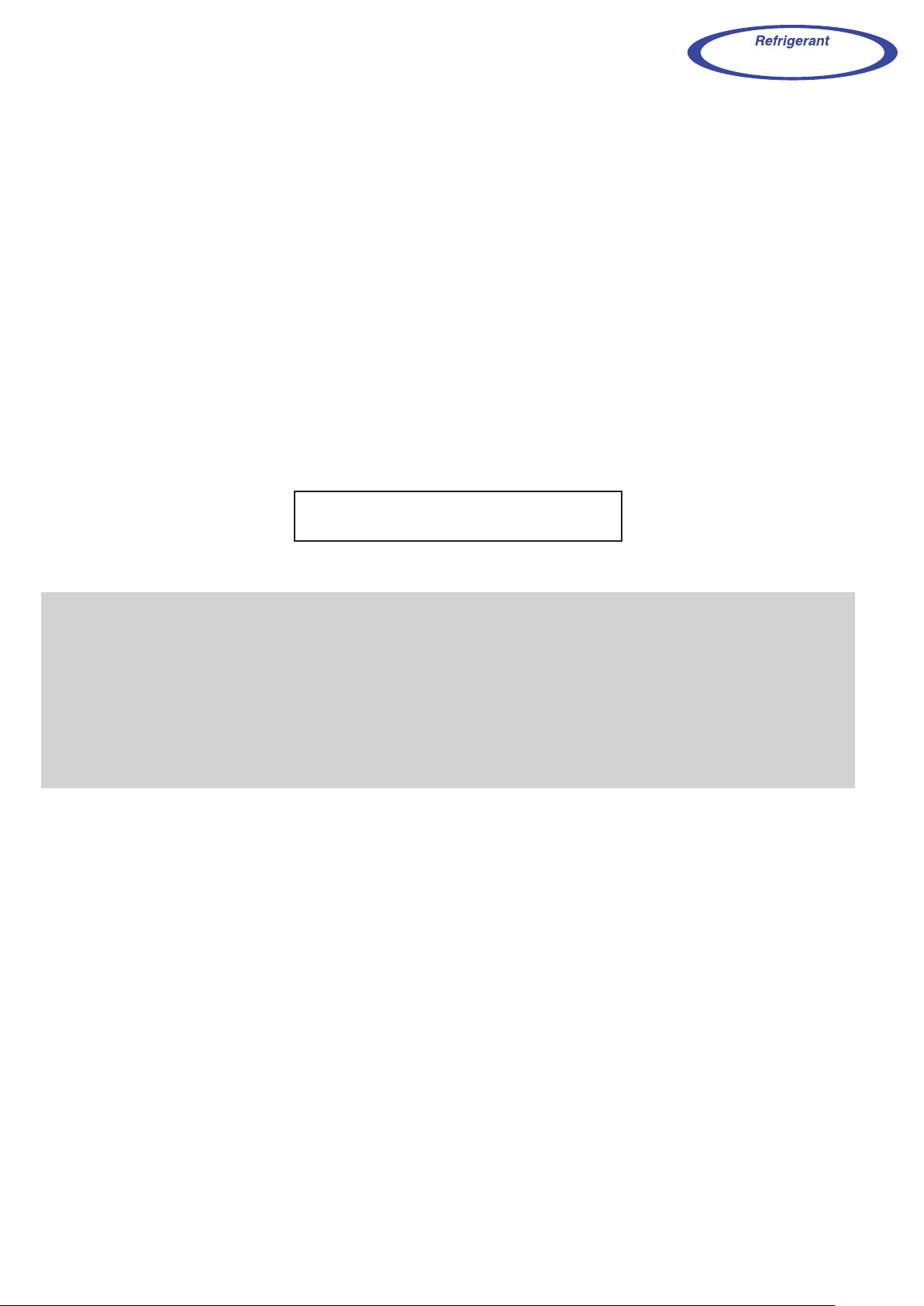
1. FEATURE
Energy Efficiency Classification A
AOV09/12LA
AOV14LA
Europe Energy Efficiency Classification A achieved
Up and down twin fan operation
Up to every corner of the room especially around the feet is heated evenly
by two-direction up and down discharge.
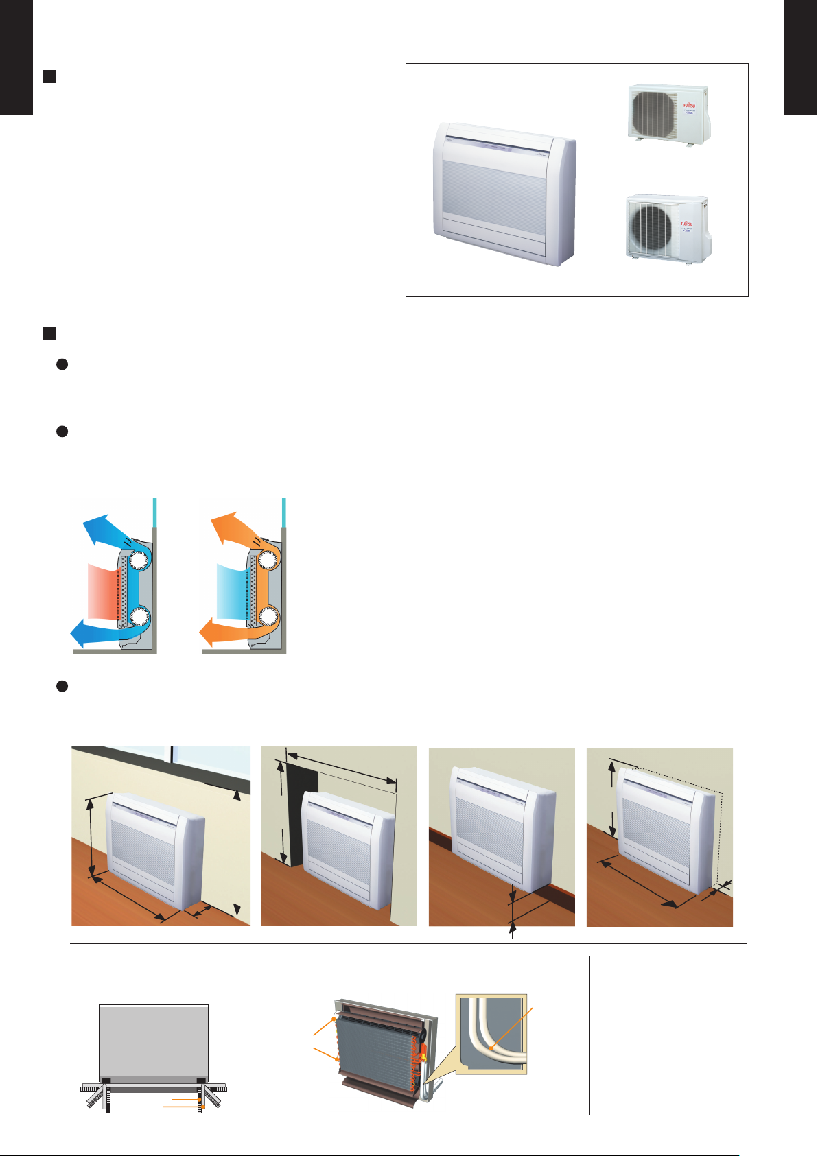
Flexible & easy installation
Piping space is wide and connection work is easy.
Cooling Heating
Fan motor
Front view
Space is wide and
piping work is easy
Large piping
bend R
Beneath standard window Standard concave portion
Wall
Half concealed (Optional parts necessary)
(unit:mm)
600
740
200
700
(unit:mm)
Min.
700
Min.
590
Min.940
)mm:tinu()mm:tinu(
Max. 150
Min. 730
Max.
80
Choice of 6-direction drain &
piping connection
Back view
Drain hose
Piping
1
6
52
3
4
Page 3
- (01 - 02) -
WALL MOUNTED TYPE
AGF09-14LA
WALL MOUNTED TYPE
AGF09-14LA
ALL DC
Super quiet operation
Air flow mode can be set in 4 steps and more detailed air flow setting is possible.
Inner drying operation
This model is equipped with an inner drying function. After the power is turned off, the dry operation
starts inside the air conditioner. This prevents the growth of mold and bacteria inside the air conditioner.
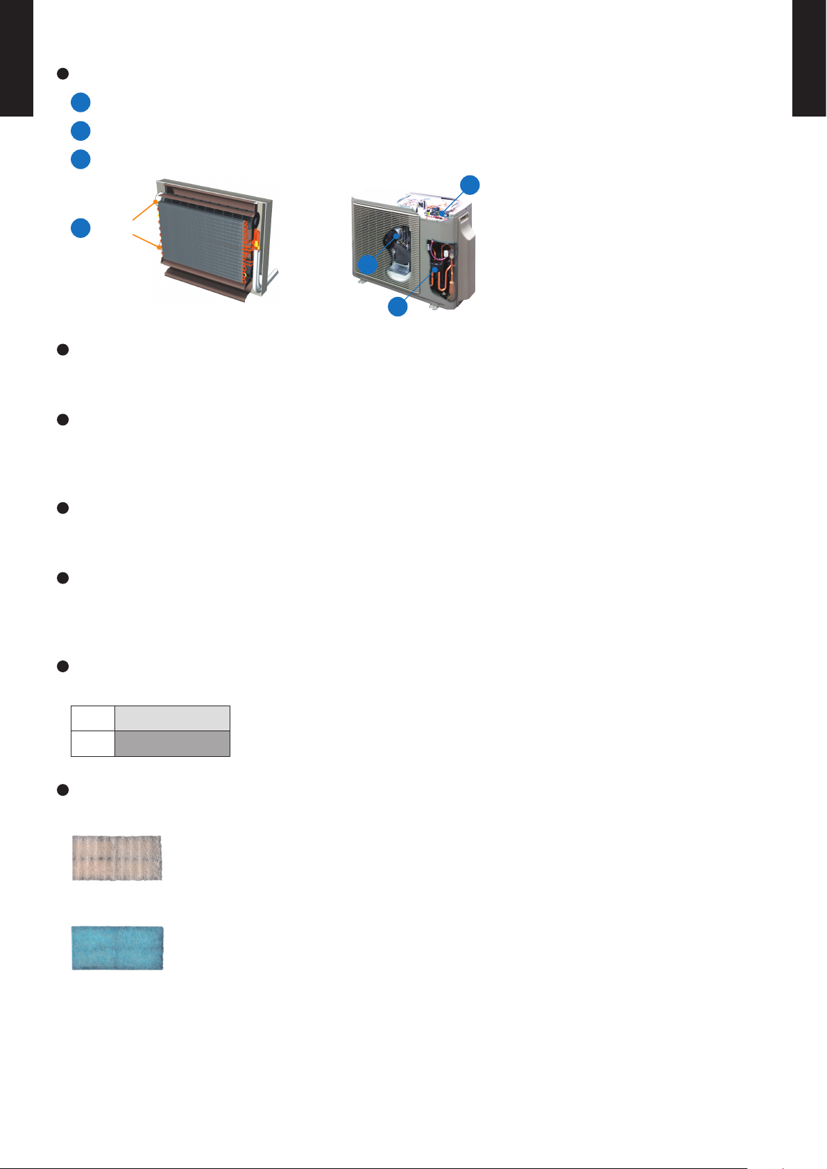
Air conditioner filter feature
Apple-catechin filter
Long-life ion deodorization filter
DC Fan motor
b
a
c
a
V-PAM control
b
DC rotary compressor
c
a
DC fan motor
Economy mode
Limits the maximum operation current, and performs operation with the power consumption suppressed.
10°C heating operation
Operates in the 10°C heating mode so that the room does not become too cold even
when you are absent during the winter, etc.
Low ambient outdoor temperature design
Low ambient outdoor temperature design
-10 to 43˚C
-15 to 24˚C
Cooling
Heating
Page 4
- (01 - 03) -
WALL MOUNTED TYPE
AGF09-14LA
WALL MOUNTED TYPE
AGF09-14LA
FEATURES
Four kinds of timer setup (ON / OFF / PROGRAM / SLEEP) are possible.
Four kinds of timers. Easy operation.
Select from four different timer programs (On/Off/Program/Sleep).
Built-in timers
The program timer operates the ON and OFF timer once within a 24 hour period.
Program timer
The sleep timer function automatically corrects the temperature thermostat setting according to the
time setting to prevent excessive cooling and heating while sleeping.
Sleep timer
2-1. WIRELESS REMOTE CONTROLLER
2.
REMOTE CONTROLLER
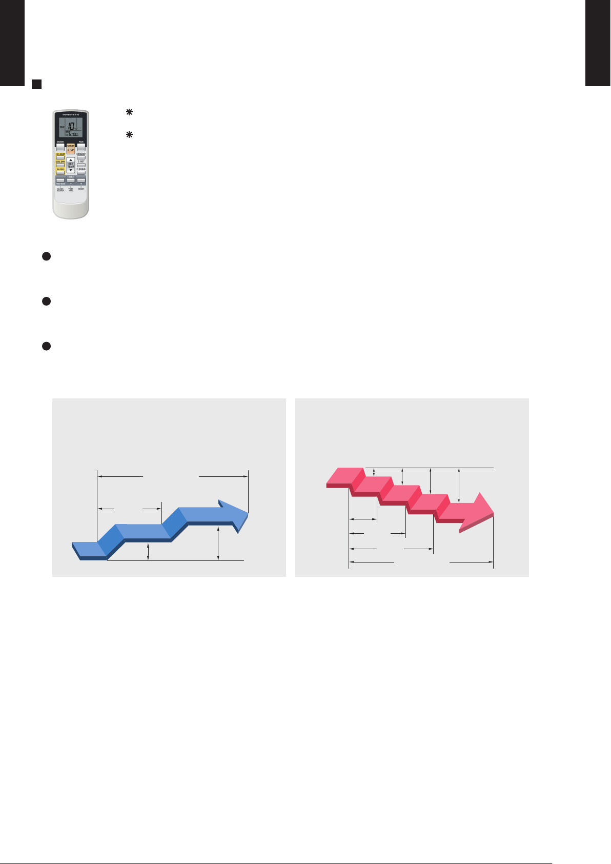
Cooling operation/dry operation
60min.
1 °C
2 °C
When the sleep timer is set, the set temperature
automatically rises 1 °C every hour. The set
temperature can rise up to a maximum of 2 °C.
Heating operation
When the sleep timer is set, the set temperature
automatically drops 1 °C every 30 minutes. The
set temperature can drop to a maximum of 4 °C.
1 °C
30min.
60min.
90min.
2 °C
3 °C
4 °C
Timer setting
Timer setting
Page 5
- (01 - 04) -
WALL MOUNTED TYPE
AGF09-14LA
WALL MOUNTED TYPE
AGF09-14LA
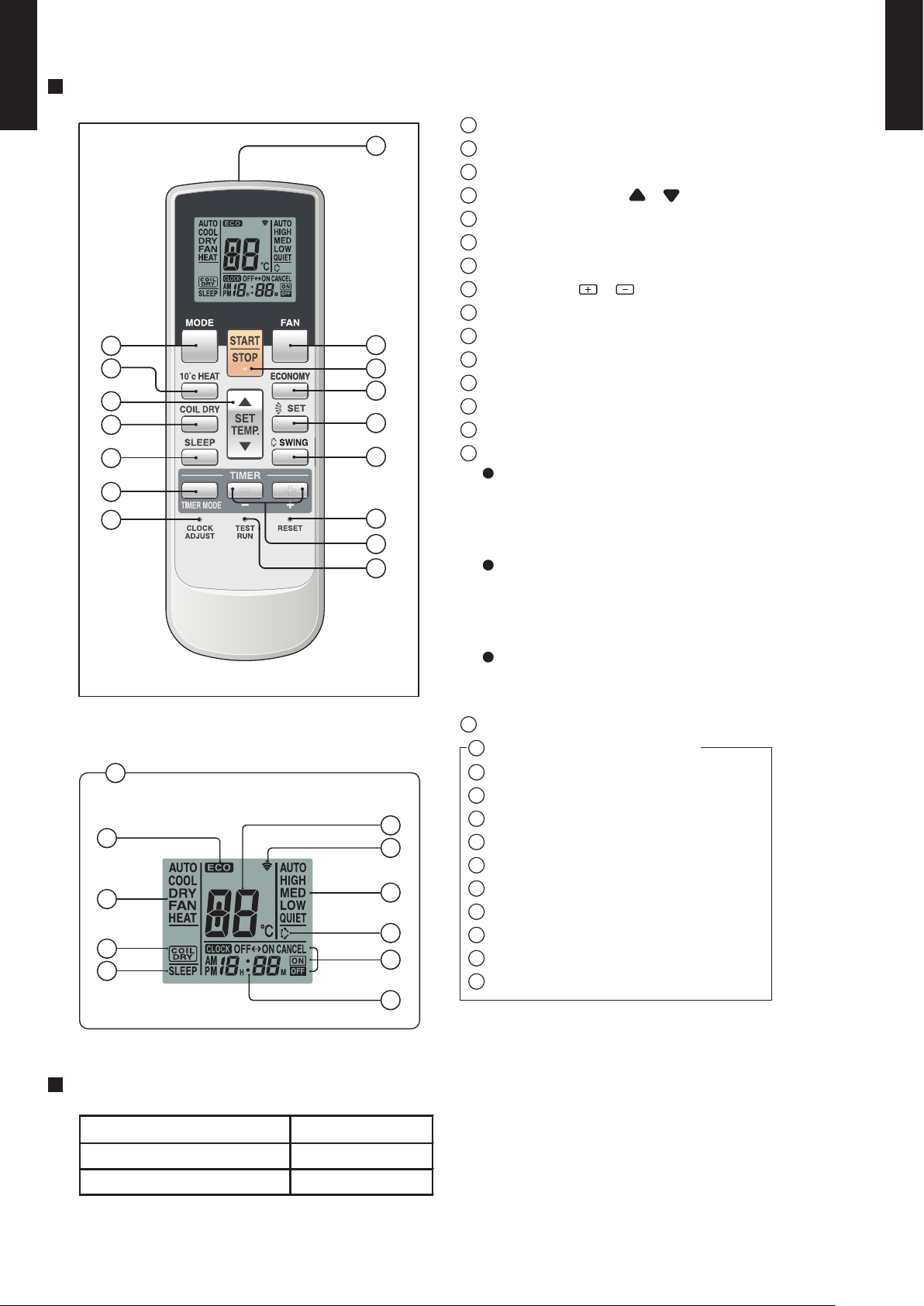
Display panel
FUNCTIONS
SPECIFICATION
SIZE (H x W x D mm) 176 x 56 x 18
WEIGHT ( g ) 110
ACCESSORY Holder
12
10
11
9
6
13
14
8
15
7
1
5
4
3
2
16
17
20
21
25
26
18
24
23
27
22
19
SLEEP button
MODE button
10°C HEAT button
SET TEMP. button (
/ )
COIL DRY button
Signal Transmitter
TIMER MODE button
TIMER SET (
/ ) button
FAN CONTROL button
ECONOMY button
START/STOP button
SET button
SWING button
RESET button
TEST RUN button
This button is used when installing the
conditioner, and should not be used under normal conditions, as it will cause the
air conditioner’s thermostat function to operate incorrectly.
If this button is pressed during normal operation, the unit will switch to test operation mode, and the Indoor Unit’s OPERATION Indicator Lamp and TIMER Indicator
Lamp will begin to flash simultaneously.
To stop the test operation mode, press the
START/STOP button to stop the air conditioner.
CLOCK ADJUST button
Remote Control Unit Display
Transmit Indicator
Clock Display
ECONOMY Display
Operating Mode Display
Timer Mode Display
Fan Speed Display
Temperature SET Display
COIL DRY Display
SLEEP Display
SWING Display
1
2
3
4
5
6
7
8
9
10
11
12
13
14
15
18
17
16
19
20
21
22
23
24
25
26
27
Page 6
- (01 - 05) -
WALL MOUNTED TYPE
AGF09-14LA
WALL MOUNTED TYPE
AGF09-14LA
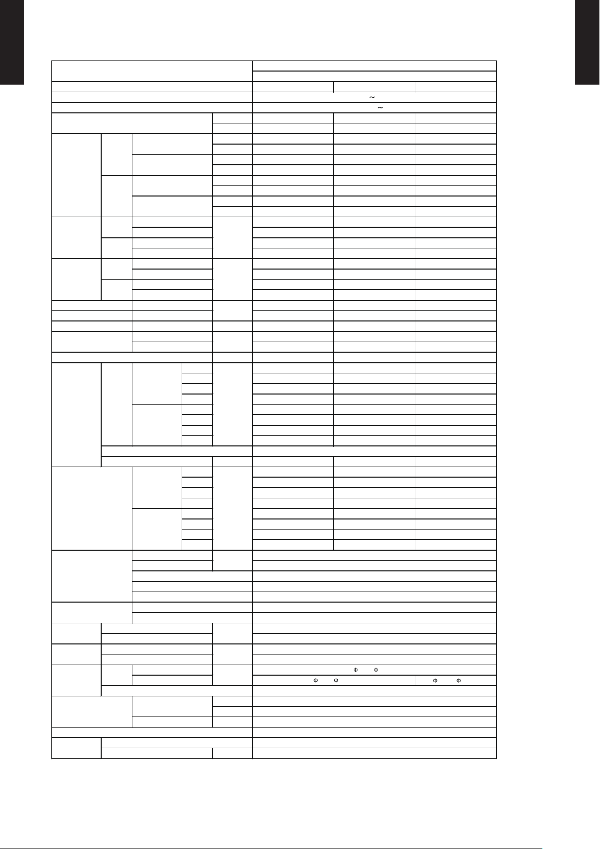
3. SPECIFICATIONS
AGF09LAC AGF12LAC AGF14LAC
Cooling A A A
Heating A A A
kW 2.60 3.50 4.20
BTU/h 8,900 11,900 14,300
kW 0.9 - 3.5 0.9 - 4.0 0.9 - 5.0
BTU/h 3,100 - 11,900 3,100 - 13,600 3,100 - 17,100
kW 3.50 4.50 5.20
BTU/h 11,900 15,400 17,700
kW 0.9 - 5.5 0.9 - 6.6 0.9 - 8.0
BTU/h 3,100 - 18,800 3,100 - 22,500 3,100 - 27,300
0.53 0.94 1.14
0.25 - 1.35 0.25 - 1.40 0.25 - 1.90
0.79 1.19 1.44
0.25 - 2.10 0.25 - 2.15 0.25 - 2.95
2.6 4.4 5.2
7.0 7.0 9.0
3.8 5.5 6.4
10 10.0 13.5
4.91 3.72 3.68
4.43 3.78 3.61
kW 2.33 2.66 3.15
90 93 96
90 94 98
l/h (pints/h) 1.3 (2.7)
1.8 (3.8) 2.1 (4.4)
High
570 570 650
Med
460 460 520
Low
360 360 400
Quiet
270 270 270
High
600 600 650
Med
480 480 520
Low
370 370 390
Quiet
270 270 270
W 42 42 42
High
40 40 44
Med
35 35 38
Low
29 29 31
Quiet
22 22 22
High
40 40 43
Med
35 35 37
Low
29 29 29
Quiet
22 22 22
12.70 ( 1/2 in.)
°C
%RH
°C
mm
Note :
Specifications are based on the following conditions.
Cooling : Indoor temperature of 27°CDB/19°CWB. and outdoor temperature of 35°CDB/24°CWB.
Heating : Indoor temperature of 20°CDB/15°CWB. and outdoor temperature of 7°CDB/6°CWB.
Pipe length : 5 m, Height difference : 0 m. (Outdoor unit - Indoor unit)
The maximum current is the maximum value when operated within the operation range (temperature).
Method
Cooling
Heating
Size
Net
Gross
Liquid
Gas
Material
Colour
Net
Gross
Type × Q'ty
Motor output
Dimensions (H × W × D)
Fin pitch
Model name
EER
COP
Moisture removal
Cross flow fan × 2
30 or less
Wireless
PP+LLDPE
700 × 820 × 310
14 (31)
17 (37)
6.35 ( 1/4 in.)
Outer diameter : 29 / Inner diameter : 13.6
9.52 ( 3/8 in.)
Flare
18 to 32
80 or less
230V 50Hz
198 - 264V 50Hz
White
600 × 740 × 200
378 × 550 × 26.6
1.2
2 × 18
Copper
Aluminium
Polystyrene
Cooling
Heating
Sound pressure level dB(A)
Type
mm
Rated
Min-Max
Rated
Min-Max
Rated
Min-Max
Power source
Available voltage range
Capacity
Cooling
Heating
European energy label
Input power
Cooling
kW
Heating
Rated
Min-Max
Current
Cooling
SENSIBLE CAPACITY
POWER FACTOR
Heating
%
Cooling
Heating
Cooling
Operation range
kg(lb.)
Heat exchanger type
Enclosure
mm
mm
Rows × Stages
Pipe type
Fin type
Remote controller type
Drain pipe
Material
FLOOR TYPE
INVERTER HEAT PUMP
Cooling
(UPPER :
LOWER)
Heating
(UPPER :
LOWER)
m3/h
A
Rated
kW/kW
Max
Rated
Max
Connection pipe
Size
Dimensions
(H × W × D)
Weight
Cooling
Heating
Fan
Airflow
rate
Page 7
- (01 - 06) -
WALL MOUNTED TYPE
AGF09-14LA
WALL MOUNTED TYPE
AGF09-14LA
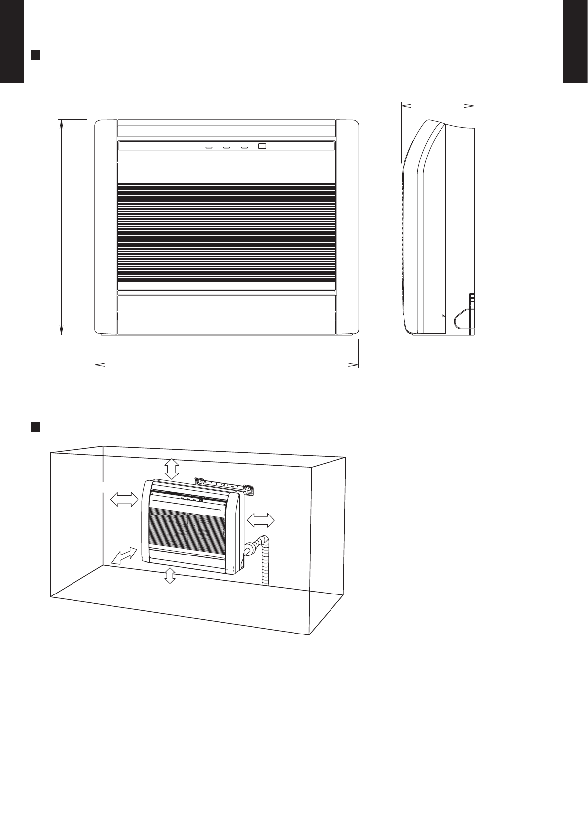
4. DIMENSIONS
(Unit : mm)
INSTALLATION PLACE
MODEL : AGF09LA, AGF12LA, AGF14LA
200
600
740
Front view
Side view
10 cm or more
8 cm or more
8 cm or more
5 cm or
more
15 cm or below
from the floor
Page 8
- (01 - 07) -
WALL MOUNTED TYPE
AGF09-14LA
WALL MOUNTED TYPE
AGF09-14LA
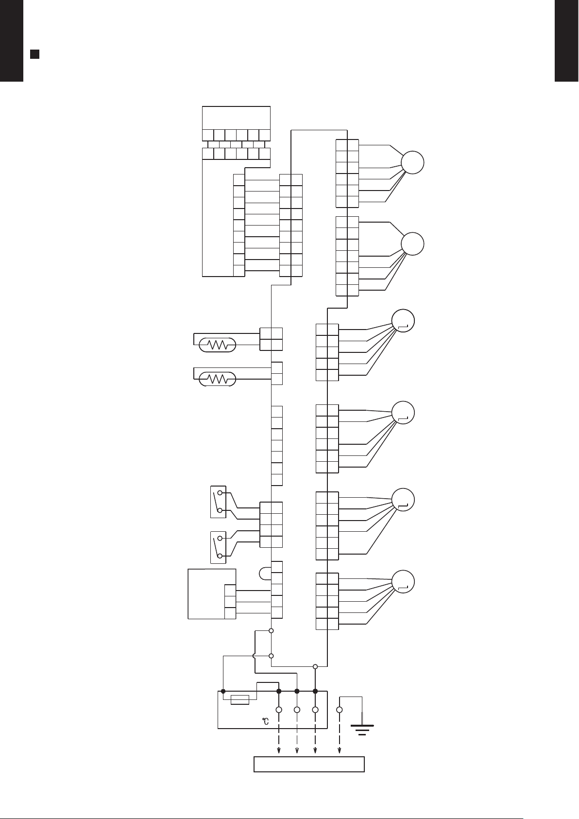
5. WIRING DIAGRAMS
MODEL : AGF09LA, AGF12LA, AGF14LA
ORANGE
YELLOW
RED
PINK
BLUE
ORANGE
YELLOW
RED
PINK
BLUE
ORANGE
YELLOW
RED
PINK
BLUE
ORANGE
YELLOW
RED
PINK
BLUE
WHITE
BLACK
RED
BLACK
BLACK
BLUE
BLUE
BLACK
BLACK
GRAY
GRAY
RED
WHITE
WHITE
WHITE
WHITE
WHITE
WHITE
WHITE
WHITE
WHITE
YELLOW
RED
BLACK
BLUE
WHITE
YELLOW
RED
BLACK
BLUE
9
8
7
6
5
4
3
2
1
7
6
5
4
3
2
1
7
6
5
4
3
2
1
6
5
4
3
2
1
6
5
4
3
2
1
5
4
3
2
1
5
4
3
2
1
7
6
5
4
3
2
1
1
2
3
4
5
6
7
8
9
1
2
3
4
5
6
1
2
3
4
5
6
7
8
9
5
4
3
2
1
4
3
2
1
4
3
2
1
2
1
2
1
2
1
4
3
2
1
4
3
2
1
565
6
4
3
2
1
5
6
4
3
2
1
5
6
4
3
2
1
5
4
3
2
1
5
4
3
2
1
5
6
CN202
CN203
CN201
CN11
CN17
CN10
CN3
CN12
CN1CN13
CN18
CN8CN5
CN6
CN2
TM1
TM5
TM2
THERMAL
FUSE 102
TERMINAL
1
2
3
STEP MOTOR
( DAMPER )
M
M
STEP MOTOR
( UP / DOWN )
STEP MOTOR
( DAMPER LOCK RIGHT )
M
STEP MOTOR
( DAMPER LOCK LEFT )
M
FAN MOTOR
( LOWER )
F M
F M
FAN MOTOR
( UPPER )
PIPE THERMISTOR
ROOM THERMISTOR
TO OUTDOOR UNIT
TEST
SWITCH
SWITCH
INDICATOR PCB ASSY
SWITCH PCB ASSY
CONTROLLER PCB ASSY ( MAIN PCB )
BLACK
WHITE
RED
3
2
1
REMOTE
CONTROL
UNIT
(OPTION)
Page 9
- (01 - 08) -
WALL MOUNTED TYPE
AGF09-14LA
WALL MOUNTED TYPE
AGF09-14LA
6. CAPACITY TABLE
6-1. COOLING CAPACITY
MODEL : AGF09LA
MODEL : AGF12LA
MODEL : AGF14LA
°CDB
°CWB
TC SHC PI TC SHC PI TC SHC PI TC SHC PI TC SHC PI TC SHC PI TC SHC PI
1.99 1.88 0.25 2.21 1.89 0.25 2.29 2.05 0.26 2.44 2.06 0.26 2.51 2.23 0.26 2.67 2.22 0.26 2.82 2.36 0.27
2.27 2.15 0.41 2.53 2.16 0.42 2.61 2.35 0.42 2.79 2.35 0.43 2.87 2.54 0.43 3.04 2.53 0.43 3.22 2.70 0.44
2.16 2.05 0.46 2.41 2.06 0.47 2.49 2.24 0.47 2.66 2.24 0.48 2.74 2.42 0.48 2.90 2.41 0.48 3.07 2.57 0.49
2.05 1.94 0.51 2.29 1.95 0.52 2.37 2.12 0.52 2.52 2.13 0.53 2.60 2.30 0.53 2.76 2.29 0.54 2.91 2.44 0.54
1.90 1.80 0.53 2.12 1.81 0.54 2.19 1.97 0.55 2.34 1.98 0.55 2.41 2.13 0.55 2.56 2.13 0.56 2.70 2.26 0.57
1.87 1.77 0.54 2.08 1.78 0.55 2.15 1.93 0.55 2.30 1.94 0.56 2.37 2.10 0.56 2.51 2.09 0.57 2.65 2.22 0.57
AFR
9.5
Indoor temperature
18212325272932
Outdoor temperature
°CDB
20
25
30
35
40
43
19212312151618
°CDB
°CWB
TC SHC PI TC SHC PI TC SHC PI TC SHC PI TC SHC PI TC SHC PI TC SHC PI
2.67 2.17 0.45 2.98 2.19 0.45 3.08 2.38 0.45 3.28 2.39 0.46 3.38 2.58 0.46 3.59 2.57 0.47 3.79 2.73 0.47
3.05 2.48 0.74 3.40 2.50 0.75 3.52 2.72 0.75 3.75 2.73 0.76 3.87 2.94 0.76 4.10 2.93 0.77 4.33 3.12 0.78
2.91 2.37 0.82 3.24 2.38 0.83 3.36 2.59 0.84 3.58 2.60 0.85 3.69 2.81 0.85 3.91 2.79 0.86 4.13 2.98 0.87
2.76 2.25 0.91 3.08 2.26 0.92 3.18 2.46 0.93 3.39 2.47 0.94 3.50 2.66 0.94 3.71 2.65 0.95 3.92 2.83 0.96
2.56 2.08 0.95 2.86 2.10 0.96 2.95 2.28 0.97 3.15 2.29 0.98 3.25 2.47 0.98 3.44 2.46 0.99 3.63 2.62 1.00
2.52 2.05 0.96 2.80 2.06 0.97 2.90 2.24 0.98 3.09 2.25 0.99 3.19 2.43 0.99 3.38 2.42 1.00 3.57 2.57 1.01
AFR
9.5
20
192116
18
Indoor temperature
182123
23
Outdoor temperature
30
35
40
43
°CDB
25
12
15
252729
32
°CDB
°CWB
TC SHC PI TC SHC PI TC SHC PI TC SHC PI TC SHC PI TC SHC PI TC SHC PI
3.42 2.61 0.62 3.81 2.63 0.63 3.94 2.86 0.63 4.20 2.87 0.64 4.33 3.10 0.64 4.59 3.08 0.65 4.85 3.28 0.66
3.66 2.80 0.91 4.08 2.81 0.92 4.22 3.06 0.93 4.50 3.07 0.93 4.64 3.31 0.94 4.91 3.30 0.95 5.19 3.51 0.96
3.50 2.67 1.00 3.90 2.69 1.02 4.03 2.92 1.02 4.30 2.93 1.03 4.43 3.16 1.04 4.69 3.15 1.05 4.96 3.36 1.06
3.32 2.53 1.10 3.70 2.55 1.12 3.82 2.77 1.12 4.07 2.78 1.13 4.20 3.00 1.14 4.45 2.99 1.15 4.70 3.18 1.16
2.94 2.25 1.14 3.28 2.26 1.16 3.39 2.46 1.17 3.61 2.47 1.18 3.73 2.66 1.19 3.95 2.65 1.20 4.17 2.82 1.21
2.78 2.12 1.16 3.10 2.13 1.17 3.20 2.32 1.18 3.41 2.33 1.19 3.52 2.51 1.20 3.73 2.50 1.21 3.94 2.67 1.22
AFR
10.8
°CDB
20
Outdoor temperature
12351819212315
16
25
30
40
43
Indoor temperature
18212325272932
AFR : Air Flow Rate (m3/min)
TC : Total Capacity (kW)
SHC : Sensible Heat Capacity (kW)
PI : Power Input (kW)
Page 10
- (01 - 09) -
WALL MOUNTED TYPE
AGF09-14LA
WALL MOUNTED TYPE
AGF09-14LA
6-2. HEATING CAPACITY
MODEL : AGF09LA
MODEL : AGF12LA
MODEL : AGF14LA
TC PI TC PI TC PI TC PI TC PI
3.53 1.44 3.45 1.47 3.37 1.50 3.28 1.53 3.20 1.56
3.67 1.54 3.58 1.57 3.50 1.60 3.41 1.63 3.32 1.67
4.18 1.61 4.08 1.64 3.98 1.68 3.88 1.71 3.78 1.74
4.84 1.72 4.72 1.75 4.61 1.79 4.49 1.82 4.38 1.86
5.35 1.72 5.23 1.76 5.10 1.80 4.97 1.83 4.84 1.87
5.46 1.38 5.33 1.41 5.20 1.44 5.07 1.47 4.94 1.50
5.14 1.39 5.02 1.42 4.89 1.45 4.77 1.48 4.65 1.51
5.42 1.16 5.29 1.19 5.16 1.21 5.03 1.24 4.90 1.26
AFR : Air Flow Rate (m3/min)
TC : Total Capacity (kW)
PI : Power Input (kW)
AFR
10.8
Indoor temperature
°CDB16182022
24
Outdoor temperature
°CDB
°CWB
-15
-16
-10
-11
-5
-7
0
-2
5
3
7
6
10
8
15
10
TC PI TC PI TC PI TC PI TC PI
3.04 0.96 2.97 0.98 2.89 1.00 2.82 1.02 2.75 1.04
3.34 1.01 3.26 1.04 3.18 1.06 3.10 1.08 3.02 1.10
3.78 1.06 3.69 1.09 3.60 1.11 3.51 1.13 3.42 1.15
4.40 1.14 4.30 1.16 4.20 1.18 4.09 1.21 3.99 1.23
4.89 1.21 4.77 1.24 4.66 1.26 4.54 1.29 4.42 1.31
4.72 1.14 4.61 1.17 4.50 1.19 4.39 1.21 4.27 1.24
5.43 1.16 5.30 1.18 5.17 1.20 5.04 1.23 4.91 1.25
5.43 1.09 5.30 1.11 5.17 1.14 5.04 1.16 4.91 1.18
AFR
10.0
Indoor temperature
°CDB16182022
24
Outdoor temperature
°CDB
°CWB
-15
-16
-10
-11
-5
-7
0
-2
5
3
7
6
10
8
15
10
TC PI TC PI TC PI TC PI TC PI
2.36 0.64 2.31 0.65 2.25 0.66 2.19 0.68 2.14 0.69
2.60 0.67 2.54 0.69 2.48 0.70 2.41 0.72 2.35 0.73
2.94 0.71 2.87 0.72 2.80 0.74 2.73 0.75 2.66 0.77
3.43 0.75 3.34 0.77 3.26 0.79 3.18 0.80 3.10 0.82
3.80 0.80 3.71 0.82 3.62 0.84 3.53 0.85 3.44 0.87
3.67 0.76 3.59 0.77 3.50 0.79 3.41 0.81 3.32 0.82
4.22 0.77 4.12 0.78 4.02 0.80 3.92 0.82 3.82 0.83
4.22 0.72 4.12 0.74 4.02 0.75 3.92 0.77 3.82 0.79
AFR
10.0
Indoor temperature
°CDB16182022
24
Outdoor temperature
°CDB
°CWB
-15
-16
-10
-11
-5
-7
0
-2
5
3
7
6
10
8
15
10
Page 11
- (01 - 10) -
WALL MOUNTED TYPE
AGF09-14LA
WALL MOUNTED TYPE
AGF09-14LA
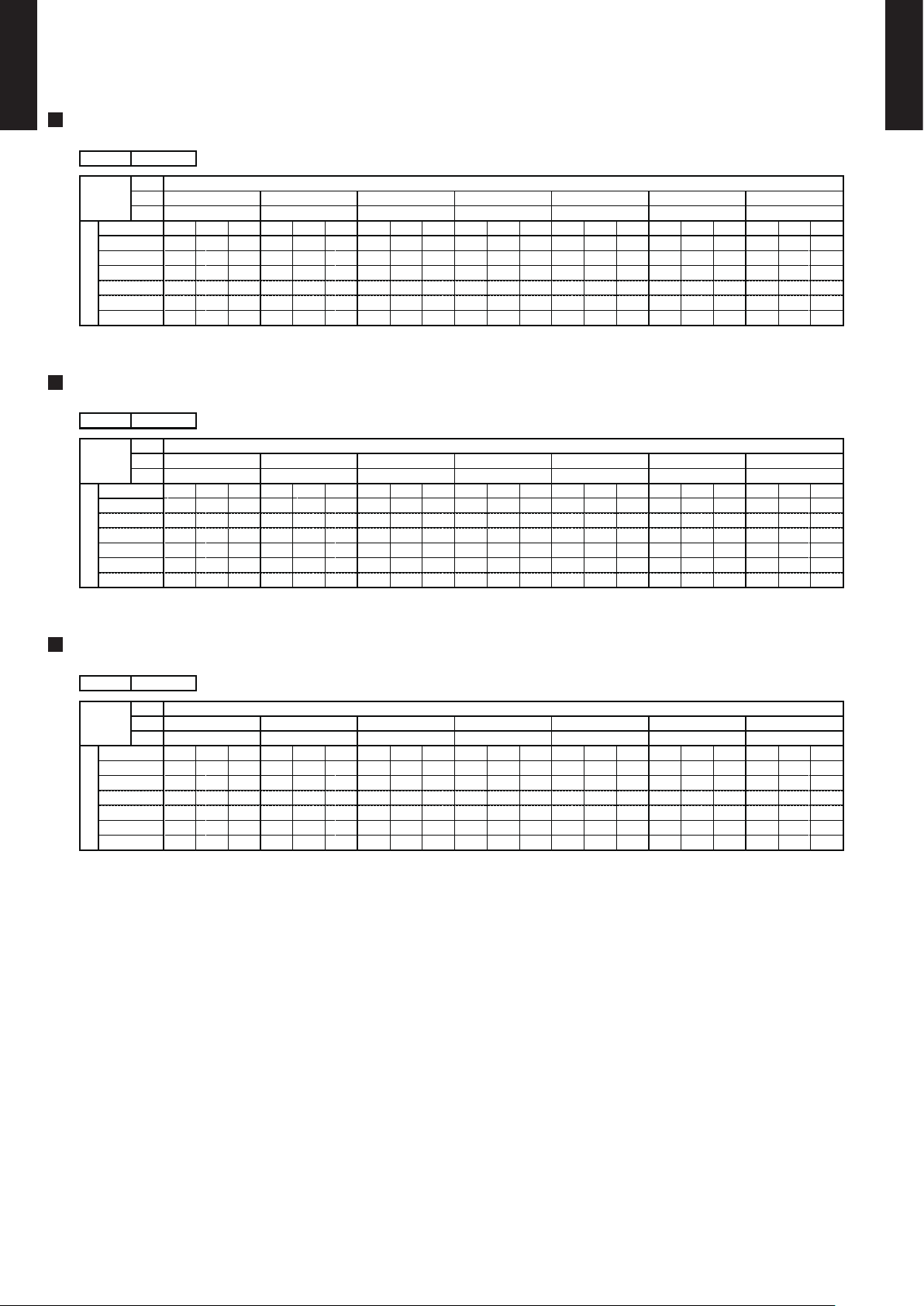
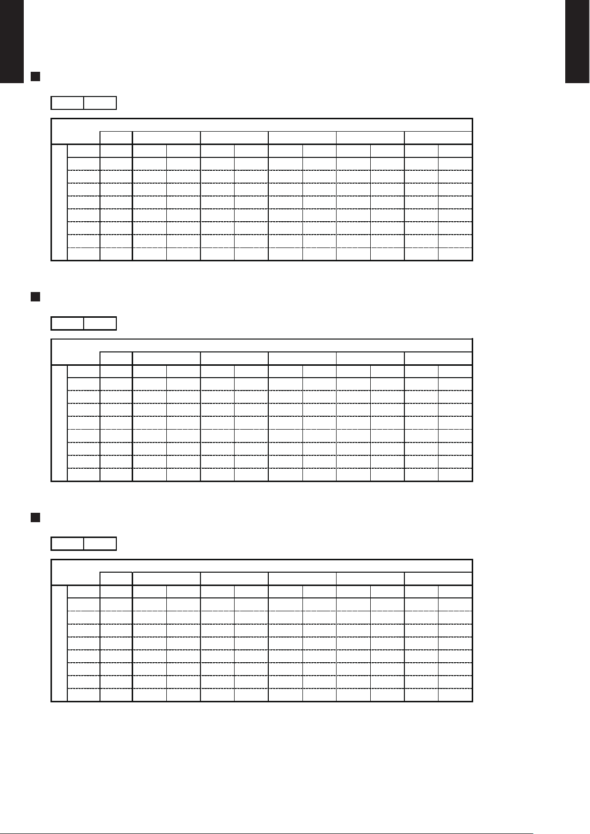
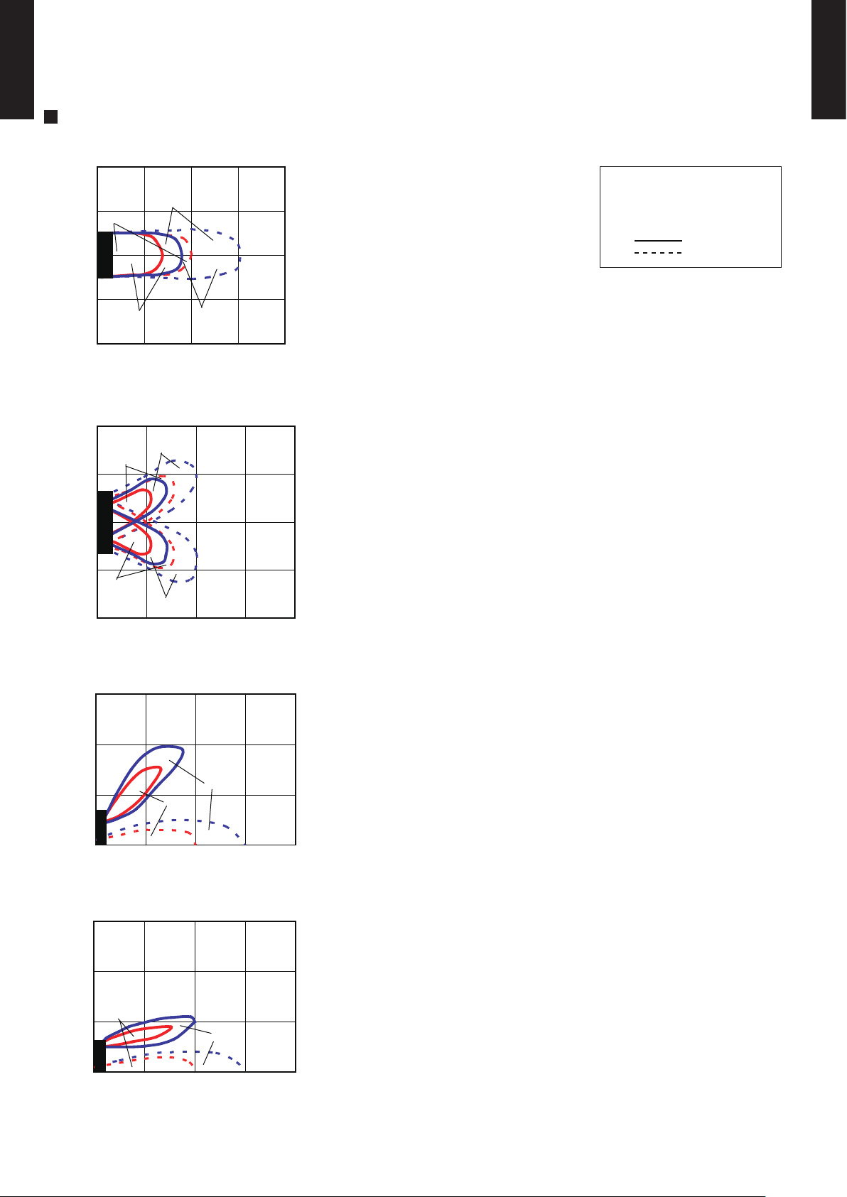
7. FAN PERFORMANCE
7-1. AIR VELOCITY DISTRIBUTION
MODEL : AGF09LA, AGF12LA, AGF14LA
Note :
Fan speed : H i
Operation : FAN
Voltage : 230V
Fan select : UPPER&LOWER
: UPPER FAN
: LOWER FAN
SIDE VIEW
FLOW CONTROL PANEL : Horiz.
LOUVER :Center
0
1
2
3
(m)
(m)
1.0
0.5
Unit: m/s
1 2 3 4
SIDE VIEW
FLOW CONTROL PANEL : Vert
LOUVER :Center
Unit: m/s
0
1
2
3
(m)
1.0
0.5
1 2 3 4
(m)
TOP VIEW
FLOW CONTROL PANEL : Horiz.
LOUVER :Right & Left
TOP VIEW
FLOW CONTROL PANEL : Horiz.
LOUVER :Center
Unit: m/s
2
1
0
1
2
(m)
(m)
0.5
1 2 3 4
UPPER
LOWER
1.0
Unit: m/s
2
1
0
1
2
(m)
(m)
0.5
1 2 3 4
1.0
0.5
1.0
Page 12

- (01 - 11) -
WALL MOUNTED TYPE
AGF09-14LA
WALL MOUNTED TYPE
AGF09-14LA
MODEL : AGF09LA, AGF12LA
COOLING
7-2. AIR FLOW
HEATING
570
m3/h
158 l/s
335 CFM
460
m3/h
128 l/s
271 CFM
360
m3/h
100 l/s
212 CFM
270
m3/h
75 l/s
159 CFM
1190/1000
1000/850
820/690
660/560
HIGH
MED
LOW
QUIET
Fan speed
Number of rotations
[r.p.m]
(UPPER/LOWER)
Air flow
600
m3/h
167 l/s
353 CFM
480
m3/h
133 l/s
282 CFM
370
m3/h
103 l/s
218 CFM
270
m3/h
75 l/s
159 CFM
QUIET
660/560
840/700
1040/880
HIGH
1240/1040
MED
LOW
Fan speed
Number of rotations
[r.p.m]
(UPPER/LOWER)
Air flow
Page 13

- (01 - 12) -
WALL MOUNTED TYPE
AGF09-14LA
WALL MOUNTED TYPE
AGF09-14LA
MODEL : AGF14LA
COOLING
HEATING
650
m3/h
181 l/s
383 CFM
520
m3/h
144 l/s
306 CFM
400
m3/h
111 l/s
235 CFM
270
m3/h
75 l/s
159 CFM
LOW
QUIET
660/560
890/750
HIGH
1330/1120
1100/930
MED
Fan speed
Number of rotations
[r.p.m]
(UPPER/LOWER)
Air flow
650
m3/h
181 l/s
383 CFM
520
m3/h
144 l/s
306 CFM
390
m3/h
108 l/s
230 CFM
270
m3/h
75 l/s
159 CFM
LOW
QUIET
860/730
660/560
HIGH
1330/1120
1100/930
MED
Fan speed
Number of rotations
[r.p.m]
(UPPER/LOWER)
Air flow
Page 14

- (01 - 13) -
WALL MOUNTED TYPE
AGF09-14LA
WALL MOUNTED TYPE
AGF09-14LA
8-1. NOISE LEVEL CURVE
8. OPERATION NOISE
COOLING
Octave band sound pressure level, dB:(0dB=0.0002µbar)
Octave band center frequency,Hz
0
10
20
30
40
50
60
70
80
63 125 250 500 1,000 2,000 4,000 8,000
COOLING
Octave band sound pressure level, dB:(0dB=0.0002µbar)
Octave band center frequency,Hz
0
10
20
30
40
50
60
70
80
63 125 250 500 1,000 2,000 4,000 8,000
HEATING
MODEL : AGF09LA
MODEL : AGF12LA
High
Quiet
High
Quiet
NC-20
NC-40
NC-50
NC-60
NC-30
NC-15
NC-25
NC-35
NC-45
NC-55
NC-65
Octave band sound pressure level, dB:(0dB=0.0002µbar)
0
10
20
30
40
50
60
70
80
Octave band center frequency,Hz
63 125 250 500 1,000 2,000 4,000 8,000
High
Quiet
NC-20
NC-40
NC-50
NC-60
NC-30
NC-15
NC-25
NC-35
NC-45
NC-55
NC-65
HEATING
Octave band sound pressure level, dB:(0dB=0.0002µbar)
Octave band center frequency,Hz
0
10
20
30
40
50
60
70
80
63 125 250 500 1,000 2,000 4,000 8,000
High
Quiet
NC-20
NC-40
NC-50
NC-60
NC-30
NC-15
NC-25
NC-35
NC-45
NC-55
NC-65
NC-20
NC-40
NC-50
NC-60
NC-30
NC-15
NC-25
NC-35
NC-45
NC-55
NC-65
Page 15

- (01 - 14) -
WALL MOUNTED TYPE
AGF09-14LA
WALL MOUNTED TYPE
AGF09-14LA
COOLING
MODEL : AGF14LA
Octave band sound pressure level, dB:(0dB=0.0002µbar)
Octave band center frequency,Hz
0
10
20
30
40
50
60
70
80
63 125 250 500 1,000 2,000 4,000 8,000
High
Quiet
NC-20
NC-40
NC-50
NC-60
NC-30
NC-15
NC-25
NC-35
NC-45
NC-55
NC-65
Octave band sound pressure level, dB:(0dB=0.0002µbar)
0
10
20
30
40
50
60
70
80
Octave band center frequency,Hz
63 125 250 500 1,000 2,000 4,000 8,000
High
Quiet
NC-20
NC-40
NC-50
NC-60
NC-30
NC-15
NC-25
NC-35
NC-45
NC-55
NC-65
HEATING
Page 16

8-2.
SOUND LEVEL CHECK POINT
Microphone Microphone
●● Air Flow
1m
Air Flow
1m
- (01 - 15) -
WALL MOUNTED TYPE
AGF09-14LA
WALL MOUNTED TYPE
AGF09-14LA
Page 17

- (01 - 16) -
WALL MOUNTED TYPE
AGF09-14LA
WALL MOUNTED TYPE
AGF09-14LA
9. ELECTRIC CHARACTERISTICS
*1) Wiring Spec.
Selected Sample
(Selected based on Japan Electrotechnical Standard and Codes Committee E0005)
AGF09LA AGF12LA AGF14LA
Voltage V
Frequency Hz
A 0.6 0.6 0.6
Circuit breaker A 0.7 0.7 0.7
Connection Cable
mm
2
1.5 - 2.5 1.5 - 2.5 1.5 - 2.5
Limited wiring length m 21 21 21
Model Name
Max Operating Current
*1)Wiring Spec.
Power Supply
230
50
Page 18

10. SAFETY DEVICES
AGF09LA AGF12LA AGF14LA
Circuit protection Current fuse (PCB)
Terminal protection Current fuse
Fan motor protection Thermal protection program
100
+15
-10
°C OFF
95
+5
-10
°C ON
Protection form
3.15A 250V
Model
3A 250V
- (01 - 17) -
WALL MOUNTED TYPE
AGF09-14LA
WALL MOUNTED TYPE
AGF09-14LA
Page 19

- (01 - 18) -
WALL MOUNTED TYPE
AGF09-14LA
WALL MOUNTED TYPE
AGF09-14LA
11. OPTIONAL PARTS
Exterior Summary
Parts name
Wired remote
controller
Apple-catechin
filter
Ion deodorisation
filter
Half concealed
kit
Model No.
UTB-UD
UTR-FC03-2
UTR-FC03-3
UTR-STA
Unit control is performed by
wired remote controller
Fine dust, invisible mold spores,
and harmful microorganisms
are absorbed onto the filter by
static electricity, and further
growth is inhibited and
deactivated by the polyphenol
ingredient extracted from
apples.
The filter deodorizes by
powerfully decomposing
absorbed odors using the
oxidizing and reducing effects
of ions generated by the ultra
fine-particle ceramic.
Using the Unit installing of half
concealed.
SUMOTUWETH FR
SA
AM
PM
3 6 9
12 15 18 21
Page 20

- (01 - 19) -
WALL MOUNTED TYPE
AGF09-14LA
WALL MOUNTED TYPE
AGF09-14LA
11-1. WIRED REMOTE CONTROLLER
High performance and compact size
Built-in timers
Easy-to-understand operation Simple installation
FEATURES
Equipped with weekly timer as standard function.
(2 times Start / Stop per day for a week)
When a failure occurs,the error code is displayed. (Maximum of 16)
Various timer setup (ON / OFF / WEEKLY) are possible.
Economy operation are possible.
Easy installation with a slim shape with no bulge in the back.
When setting up a timer, operation mode and a temperature
setup can be changed.
Error indication.(A maximum of 16 error histories are memorizable.)
Up to 16 indoor units can be simultaneously controlled.
The room temperature can be controlled by being detected the temperature
accurately with built-in thermo sensor.
Wired
remote
controller
Weekly
timer
Setback
timer
Three functions are combined in
one unit.
Simple function setting
Setting of the air conditioner selection function is performed by remote controller.
0 3 6 9 12 15 18 21 Time
24°C
0 3 6 9 12 15 18 21 Time
28°C
SUMOTUWETH FR SA
7
3126 9
15 18 21
Easy-to-understand time bar display
Setup screen example
(Set to Wednesday: 8:00 to 20:00.)
Screen
after setup
SUMOTUWETH FR SA
7
3126 9
15 18 21
Setup screen example
(Set from Sunday to Saturday: 12:00 to 15:00, 28 °C.)
SUMOTUWETH FR SA
3126 9
15 18 21
Setback timerWeekly timer
At "Weekly timer" + "Set back timer" setup
Possible to set ON/OFF time to operate twice each day
of the week.
Possible to set temperature for two time spans and
for each day of the week.
24°C
0 3 6 9 12 15 18 21 Time
28°C
24°C 28°C 24°C
Timer
area
Operation
area
Components are compatible with standard
switch boxes. Flat back construction allows
equipment to be installed wherever it is
needed.
[
Variable timer control
]
The operation/display sections are zoned according to time and operation, enabling variable programming to match application.
European
switch box
JIS box
Page 21

- (01 - 20) -
WALL MOUNTED TYPE
AGF09-14LA
WALL MOUNTED TYPE
AGF09-14LA
Display panel
DIMENSION
SPECIFICATION
120
17
[ Unit : mm ]
SIZE (H x W x D mm) 120 x 120 x 17
WEIGHT ( g ) 160
CABLE LENGTH ( m )
POWER ( V )
10
12
15
11
10
9
8
2
1
3
5
14
4
12
13
6
7
17
16
18
19
20
21
120
Front View
FUNCTIONS
Defrost display
Thermo sensor display
Economy display
Vertical swing display
Horizontal swing display *1)
Filter display
1
START/STOP button
Pressed to start and stop operation.
13
Horizontal airflow direction and swing button *1)
Push for two seconds to change the swing mode.
5
Economy button
Turns the economy efficient mode on and off.
8
Set back button
Pressed select the set back timer.
14
Filter button
12
Vertical airflow direction and swing button
Push for two seconds to change the swing mode.
9
Set time button
Pressed to set time.
17
Operation mode display
7
Day (DAY OFF) button
Temporarily cancels of one day timer.
6
Timer mode (CLOCK ADJUST) button
Selects the timer mode (OFF TIMER, ON TIMER, WEEKLY TIMER)
Set the current time.
10
Delete button
The schedule of a weekly timer is deleted.
Master control button
Selects the operating mode(AUTO, HEAT, FAN, COOL, DRY).
3
4
Fan control button
Selects the fan speed (AUTO, QUIET, LOW, MED, HIGH).
18
Fan speed display
16
Timer and clock display
Operation lamp
Lights during operation and when the timer is on.
15
20
Temperature display
21
Function display
19
Operation lock display
Set temperature button
Selects the setting temperature.
2
11
Set button
Sets the date, hour, minute and on-off time.
*1) Button number cannot be operated.
13
Page 22

R410A
D1D_AO006E/02
2008.02.20
2.
SINGLE TYPE :
AO V09LAC
AO V12LAC
AO V14LAC
OUTDOOR UNIT
Page 23

- (02 - 01) -
OUTDOOR UNIT
AO V09-12-14LA
OUTDOOR UNIT
AO V09-12-14LA
1. SPECIFICATIONS
AO V09LAC AO V12LAC AO V14LAC
A 3.8 5.5 6.4
1,680 1,680 1,910
1,490 1,680 1,750
Propeller fan × 1 Propeller fan × 1 Propeller fan × 1
W 56
47 48 50
48 49 50
504 × 850 × 36.4 504 × 850 × 36.4 546 × 876 × 36.4
1.40 1.40 1.30
2 × 24 2 × 24 2 × 26
Copper Copper Copper
Aluminium Aluminium Aluminium
Rotary × 1 Rotary × 1 Rotary × 1
W 750 750 1,100
R410A R410A R410A
g 1,050 1,050 1,150
ESTER OIL ESTER OIL ESTER OIL
Steel Steel Steel
Beige Beige Beige
540 × 790 × 290 540 × 790 × 290 578 × 790 × 300
648 × 910 × 380 648 × 910 × 380 648 × 910 × 380
36 (79) 36 (79) 40 (88)
40 (88) 40 (88) 44 (97)
12.70 ( 1/2 in.)
Note :
Specifications are based on the following conditions.
Cooling : Indoor temperature of 27°CDB/19 °CWB. and outdoor temperature of 35°CDB/24°CWB.
Heating : Indoor temperature of 20°CDB/15°CWB. and outdoor temperature of 7°CDB/6°CWB.
Pipe length : 5 m, Height difference : 0 m. (Outdoor unit - Indoor unit)
Material
Colour
Net
Gross
Motor output
Type
Charge
Type
Rows × Stages
Pipe type
Fin type
Type × Q'ty
Motor output
Cooling
Heating
Dimensions (H × W × D)
Type
Model name
Power source
Available voltage range
-15 to 24
Flare
20 (chargeless : 15)
15
-10 to 43
230V 50Hz
198 - 264V 50Hz
9.52 ( 3/8 in.)
6.35 ( 1/4 in.)
m
Connection pipe
Size
mm
Liquid
Gas
Method
Max. length
Max. height difference
Compressor
Refrigerant
Sound pressure level
Starting current
Cooling
Heating
Type × Q'ty
mm
mm
Weight
kg(lb.)
Dimensions
(H × W × D)
Refrigerant oil
Enclosure
Heat exchanger type
Fin pitch
Net
INVERTER HEAT PUMP
°C
Operation range
Fan
Airflow
rate
m3/h
dB(A)
Gross
Cooling
Heating
33 33
Page 24

- (02 - 02) -
OUTDOOR UNIT
AO V09-12-14LA
OUTDOOR UNIT
AO V09-12-14LA
2. DIMENSIONS
MODEL : AO V09LA, AO V12LA
(Unit : mm)
INSTALLATION PLACE
347
578
48
10
320
508
540
20
300
125
60
790
540
790
56
290
353
17
MODEL : AO V14LA
100 mm or more
600 mm or more
100 mm or more
200 mm or more
250 mm or
more
50 mm or more
540 125
Page 25

- (02 - 03) -
OUTDOOR UNIT
AO V09-12-14LA
OUTDOOR UNIT
AO V09-12-14LA
MODEL : AO V09LA, AO V12LA, AO V14LA
3. REFRIGERANT CIRCUIT
2-Way
valve
Strainer
Strainer
3-Way
valve
Muffler
4-Way valve
Expansion valve
Indoor unit
Heat exchanger
Outdoor unit
Heat exchanger
Compressor
Refrigerant direction
Heating
Cooling
Page 26

- (02 - 04) -
OUTDOOR UNIT
AO V09-12-14LA
OUTDOOR UNIT
AO V09-12-14LA
MODEL : AO V09LA, AO V12LA, AO V14LA
4. WIRING DIAGRAMS
WHITE
RED
YELLOW
YELLOW
BLACK
BLACK
BROWN
BROWN
BLACK
BLACK
RED
WHITE
BLACK
GREEN
BLACK
BLACK
BLACK
WHITE
BLACK
BLACK
WHITE
YELLOW
ORANGE
BLUE
BROWN
RED
BLUE
YELLOW
WHITE
BLACK
RED
BLACK
WHITE
RED
BLACK
WHITE
RED
1
2
3
4
5
6
1
2
3
1
2
3
4
5
6
1
2
3
4
5
6
1
2
3
4
5
6
1
2
3
1
2
3
1
2
3
4
1
2
3
4
1
2
3
1
2
3
221
1
1
2
3
CN71
CN70
W10
W11
W4
W2
W1
W3
CN30
CN40
CN800
W7
W8
W9
FUSE
250V
20A
FUSE
250V 15A
TERMINAL
TO INDOOR UNIT POWER SOURCE
L N32
1
4-WAY VALVE
EXPANSION VALVE
FAN MOTOR
COMPRESSOR
PIPE THERMISTOR
DISCHARGE PIPE THERMISTOR
OUTDOOR THERMISTOR
CM
FM
PMV
S ( S )
R ( R )
C ( T )
4WV
WHITE
RED
REACTOR
AO V09, 12L
AO V14L
Page 27

- (02 - 05) -
OUTDOOR UNIT
AO V09-12-14LA
OUTDOOR UNIT
AO V09-12-14LA
5. CAPACITY COMPENSATION RATE FOR PIPE LENGTH
AND HEIGHT DIFFERENCE
MODEL : AO V09LA, AO V12LA
Indoor unit
Height difference H
Connection pipe
H
Outdoor unit
Indoor unit
Connection pipe
H
Outdoor unit
Indoor unit is upper than outdoor unit.
1
Indoor unit is under than outdoor unit.
2
5 7.5 10 15 20
15 - - - 0.915 0.905
10 - - 0.955 0.922 0.912
7.5 - 0.974 0.959 0.926 0.916
5 0.992 0.978 0.963 0.930 0.920
0 1.000 0.986 0.971 0.937 0.927
-5 1.000 0.986 0.971 0.937 0.927
-7.5 - 0.986 0.971 0.937 0.927
-10 - - 0.971 0.937 0.927
-15 - - - 0.937 0.927
5 7.5 10 15 20
15 - - - 0.863 0.846
10 - - 0.944 0.863 0.846
7.5 - 0.978 0.944 0.863 0.846
5 1.000 0.978 0.944 0.863 0.846
0 1.000 0.978 0.944 0.863 0.846
-5 0.995 0.973 0.939 0.858 0.842
-7.5 - 0.971 0.937 0.856 0.840
-10 - - 0.934 0.854 0.838
-15 - - - 0.794 0.778
HEATING
COOLING
1
Indoor unit is upper
than outdoor unit.
2
Indoor unit is under
than outdoor unit
Height
difference H
(m)
Pipe length (m)
Pipe length (m)
Height
difference H
(m)
1
Indoor unit is upper
than outdoor unit.
2
Indoor unit is under
than outdoor unit
Page 28

- (02 - 06) -
OUTDOOR UNIT
AO V09-12-14LA
OUTDOOR UNIT
AO V09-12-14LA
MODEL : AO V14LA
Indoor unit
Height difference H
Connection pipe
H
Outdoor unit
Indoor unit
Connection pipe
H
Outdoor unit
Indoor unit is upper than outdoor unit.1 Indoor unit is under than outdoor unit.2
5 7.5 10 15 20
15 - - - 0.950 0.946
10 - - 0.976 0.958 0.954
7.5 - 0.984 0.980 0.962 0.958
5 0.992 0.988 0.984 0.966 0.962
0 1.000 0.996 0.992 0.974 0.969
-5 1.000 0.996 0.992 0.974 0.969
-7.5 - 0.996 0.992 0.974 0.969
-10 - - 0.992 0.974 0.969
-15 - - - 0.974 0.969
5 7.5 10 15 20
15 - - - 0.853 0.824
10 - - 0.943 0.853 0.824
7.5 - 0.982 0.943 0.853 0.824
5 1.000 0.982 0.943 0.853 0.824
0 1.000 0.982 0.943 0.853 0.824
-5 0.995 0.977 0.938 0.848 0.820
-7.5 - 0.975 0.936 0.846 0.818
-10 - - 0.933 0.844 0.816
-15 - - - 0.785 0.758
Height
difference H
(m)
1
Indoor unit is upper
than outdoor unit.
2
Indoor unit is under
than outdoor unit
Pipe length (m)
Pipe length (m)
HEATING
COOLING
1
Indoor unit is upper
than outdoor unit.
2
Indoor unit is under
than outdoor unit
Height
difference H
(m)
Page 29

- (02 - 07) -
OUTDOOR UNIT
AO V09-12-14LA
OUTDOOR UNIT
AO V09-12-14LA
6. ADDITIONAL CHARGE CALCULATION
MODEL : AO V09LA, AO V12LA, AO V14LA
REFRIGERANT CHARGE
Refrigerant amount g
Pipe length m 15 20
Additional charge g 0 (Chargeless) +100
MODEL
Refrigerant type
20g/m
AO V09LA
AO V12LA
AO V14LA
R410A
1,050
R410A
1,150
R410A
1,050
Page 30

- (02 - 08) -
OUTDOOR UNIT
AO V09-12-14LA
OUTDOOR UNIT
AO V09-12-14LA
MODEL : AO V09LA, AO V12LA, AO V14LA
COOLING
7. AIR FLOW
HEATING
MODEL
Number of rotations r.p.m. 760 r.p.m. 760 r.p.m. 820
m3/h
1680
m3/h
1680
m3/h
1910
l/s 467 l/s 467 l/s 531
CFM 989 CFM 989 CFM 1124
MODEL
Number of rotations r.p.m. 680 r.p.m. 760 r.p.m. 750
m3/h
1490
m3/h
1680
m3/h
1750
l/s 414 l/s 467 l/s 486
CFM 877 CFM 989 CFM 1030
Air flow
Air flow
AO V14LA
AO V14LA
AO V09LA
AO V09LA
AO V12LA
AO V12LA
Page 31

- (02 - 09) -
OUTDOOR UNIT
AO V09-12-14LA
OUTDOOR UNIT
AO V09-12-14LA
8-1. NOISE LEVEL CURVE
8. OPERATION NOISE
MODEL : AO V09LA
MODEL : AO V09LA MODEL : AO V12LA
COOLING
HEATING
MODEL : AO V12LA
Octave band sound pressure level, dB:(0dB=0.0002µbar)
Octave band center frequency,Hz
0
10
20
30
40
50
60
70
80
63 125 250 500 1,000 2,000 4,000 8,000
NC-20
NC-40
NC-50
NC-60
NC-30
NC-15
NC-25
NC-35
NC-45
NC-55
NC-65
Octave band sound pressure level, dB:(0dB=0.0002µbar)
0
10
20
30
40
50
60
70
80
Octave band center frequency,Hz
63 125 250 500 1,000 2,000 4,000 8,000
NC-20
NC-40
NC-50
NC-60
NC-30
NC-15
NC-25
NC-35
NC-45
NC-55
NC-65
Octave band sound pressure level, dB:(0dB=0.0002µbar)
Octave band center frequency,Hz
0
10
20
30
40
50
60
70
80
63 125 250 500 1,000 2,000 4,000 8,000
NC-20
NC-40
NC-50
NC-60
NC-30
NC-15
NC-25
NC-35
NC-45
NC-55
NC-65
Octave band sound pressure level, dB:(0dB=0.0002µbar)
Octave band center frequency,Hz
0
10
20
30
40
50
60
70
80
63 125 250 500 1,000 2,000 4,000 8,000
NC-20
NC-40
NC-50
NC-60
NC-30
NC-15
NC-25
NC-35
NC-45
NC-55
NC-65
Page 32

- (02 - 10) -
OUTDOOR UNIT
AO V09-12-14LA
OUTDOOR UNIT
AO V09-12-14LA
MODEL : AO V14LA
MODEL : AO V14LA
COOLING
HEATING
Octave band sound pressure level, dB:(0dB=0.0002µbar)
Octave band center frequency,Hz
0
10
20
30
40
50
60
70
80
63 125 250 500 1,000 2,000 4,000 8,000
NC-20
NC-40
NC-50
NC-60
NC-30
NC-15
NC-25
NC-35
NC-45
NC-55
NC-65
Octave band sound pressure level, dB:(0dB=0.0002µbar)
0
10
20
30
40
50
60
70
80
Octave band center frequency,Hz
63 125 250 500 1,000 2,000 4,000 8,000
NC-20
NC-40
NC-50
NC-60
NC-30
NC-15
NC-25
NC-35
NC-45
NC-55
NC-65
Page 33

- (02 - 11) -
OUTDOOR UNIT
AO V09-12-14LA
OUTDOOR UNIT
AO V09-12-14LA
8-2. SOUND LEVEL CHECK POINT
Page 34

- (02 - 12) -
OUTDOOR UNIT
AO V09-12-14LA
OUTDOOR UNIT
AO V09-12-14LA
9. ELECTRIC CHARACTERISTICS
AO V09LA AO V12LA AO V14LA
Voltage V
Frequency Hz
A 10.0 10.0 13.5
A 3.8 5.5 6.4
Main Fuse (Circuit breaker)
Current
A 20 20 20
Power Cable
mm
2
1.5 - 2.5 1.5 - 2.5 1.5 - 2.5
*2)Limited wiring length m 15 15 11
*1) Wiring Spec.
Selected Sample
(Selected based on Japan Electrotechnical Standard and Codes Committee E0005)
*2) Limited Wiring length :
This is the wiring length in case voltage descent is less than 2%.
When the wiring length becomes long, please select the wiring of a more larger diameter.
Model Name
Power Supply
*1) Wiring Spec.
230
50
Max Operating Current
Starting Current
Page 35

- (02 - 13) -
OUTDOOR UNIT
AO V09-12-14LA
OUTDOOR UNIT
AO V09-12-14LA
10. SAFETY DEVICES
Fan motor protection Thermal protection program
Compressor protection
Thermal protection program
(DISCHARGE TEMP.)
OFF : 100
+15
-10
°C
ON : 95
+15
-10
°C
OFF : 110°C
ON : After 7 minutes
20A 250V
5A 250V
15A 250V
3.15A 250V
15A 250V
3.15A 250V
OFF : 100
+15
-10
°C
ON : 95
+15
-10
°C
OFF : 110°C
ON : After 7 minutes
Protection form
20A 250V
5A 250V
AO V09LA
Model
AO V14LA
20A 250V
5A 250V
AO V12LA
15A 250V
3.15A 250V
Circuit protection
OFF : 110°C
ON : After 7 minutes
Current fuse
(NEAR THE TERMINAL)
Current fuse
(MAIN PRINTED CIRCUIT BOARD)
OFF : 100
+15
-10
°C
ON : 95
+15
-10
°C
 Loading...