

Page 1
SPLIT TYPE
ROOM AIR CONDITIONER
FLOOR CONSOLE /
UNDER CEILING
DUAL TYPE
Indoor unit Outdoor unit
ABHF18LAT
ABHF18LAT
ABHF24LAT
ABHF24LAT
AOHA18LACL
AOHA18LALL
AOHA24LACL
AOHA24LALL
CONTENTS
SPECIFICATIONS
OUTLINE AND DIMENSIONS
REFRIGERANT SYSTEM DIAGRAM
CIRCUIT DIAGRAM
PCB CIRCUIT DIAGRAM
ERROR DISPLAY
PARTS (indoor unit)
PARTS (outdoor unit)
ACCESSORIES
. . . . . . . . . . . . . . . . . . .
. . . . . . . . .
. . . . . . . . . . . . . . . . .
. . . . . . . . . . . . .
. . . . . . . . . . . . . . . . . .
. . . . . . . . . . . . . . . .
. . . . . . . . . . . . . . .
. . . . . . . . . . . . . . . . . . .
. . .
1
2
5
6
7
13
16
26
29
Page 2
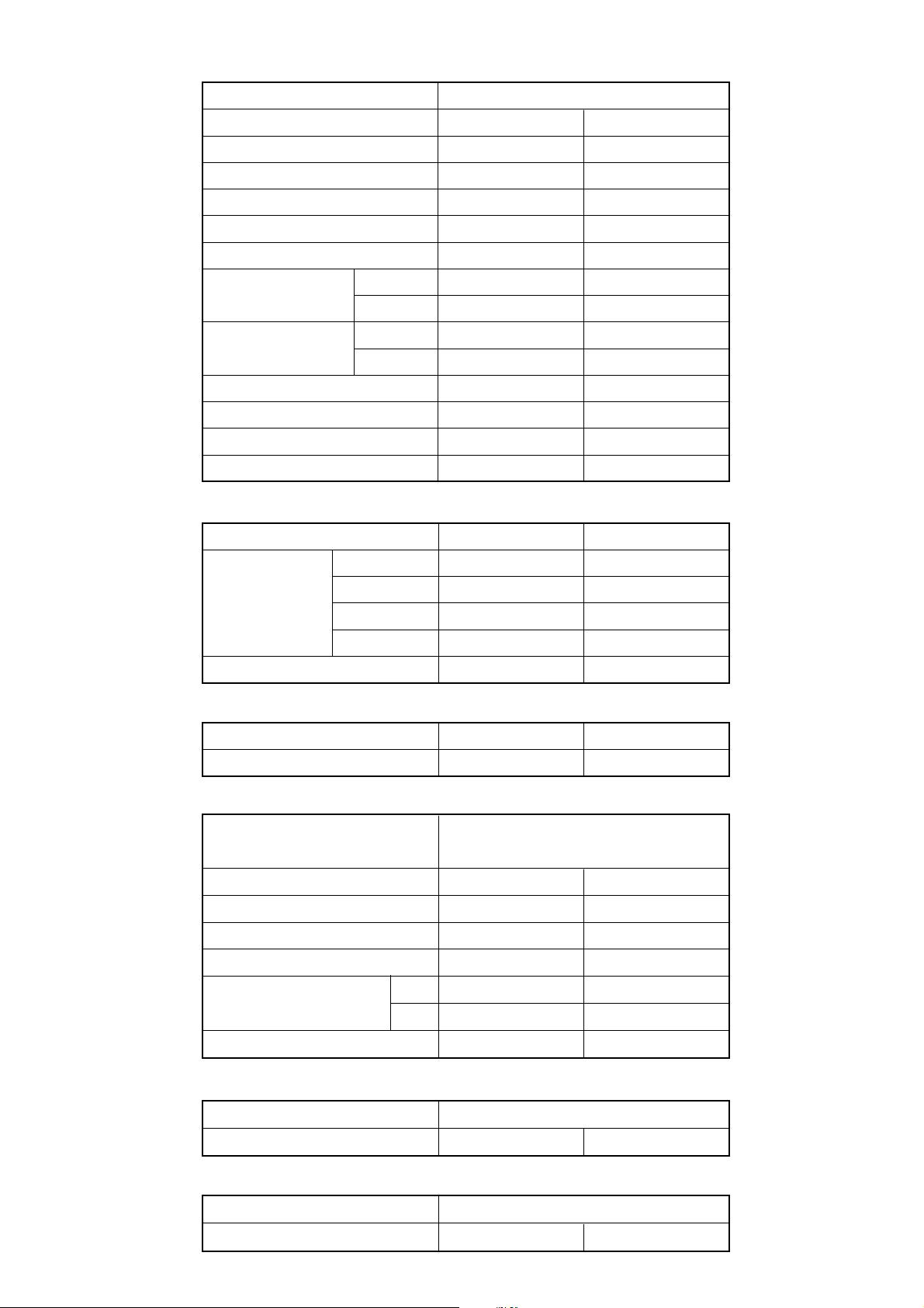
SPECIFICATIONS
ELECTRICAL DATA
TYPE
Cool & heat inverter
INDOOR UNIT ABHF18LAT
OUTDOOR UNIT AOHA18LA_L
COOLING CAPACITY 5.20 kW
HEATING CAPACITY
POWER SOURCE
FREQUENCY
RUNNING
CURRENT
INPUT WATTS
E.E.R.
COP
MOISTURE REMOVAL
AIR CIRCULATION HIGH
COOLING
HEATING
COOLING 1.62 kW
HEATING
COOLING
HEATING 3.61 kW/kW
6.00 kW
230 V
50 Hz
7.1 A
7.3 A
1.66 kW
3.21 kW/kW
2.0 L/hr
780 m3/hr
FAN MOTOR
POWER SOURCE 230 V
High speed 1,040 / 1,040 r.p.m.
ABHF24LAT
AOHA24LA_L
7.10 kW
8.00 kW
230 V
50 Hz
9.7 A
9.7 A
2.21 kW
2.21 kW
3.21 kW/kW
3.61 kW/kW
2.7 L/hr
980 m3/hr
230 V
1,330 / 1,300 r.p.m.
INDOOR UNIT
( cool / heat )
OUTDOOR UNIT
Middle
Low
Quiet 740 / 740 r.p.m.
950 / 950 r.p.m.
800 / 800 r.p.m.
860 / 820 r.p.m.
NOISE LEVEL
INDOOR UNIT ( cool / heat )
OUTDOOR UNIT ( cool / heat )
43 dB / 43 dB
50 dB / 50 dB
COMPRESSOR AND REFRIGERANT
TYPE
DISCRIMINATION DA130A1F-25NA
WEIGHT (with oil)
PRECHARGED REFRIGERANT
REFRIGERANT TYPE
Pipe length
FULL CHARGE
15 m
20 m
Hermetic type, 4 pole, 3 phase,
DC inverter motor, Rotary
9.6 kg 10.0 kg
1,250 g
R410A R410A
1,250 g
1,350 g
1,150 / 1,150 r.p.m.
1,000 / 1,000 r.p.m.
780 / 780 r.p.m.
1,050 / 1,050 r.p.m.
48 dB / 48 dB
52 dB / 53 dB
DA150A1F-20NA
1,700 g
1,700 g
1,800 g
ADDITIONAL REFRIGERANT
DIMENSIONS
INDOOR UNIT
OUTDOOR UNIT
H x W x D
H x W x D
578 x 790 x 300 mm
WEIGHT
INDOOR UNIT
OUTDOOR UNIT
2008.07.30 1
Gross / Net
Gross / Net
20 g/m
199 x 990 x 655 mm
36 kg / 27 kg
44 kg / 40 kg
20 g/m
578 x 790 x 315 mm
48 kg / 44 kg
Page 3
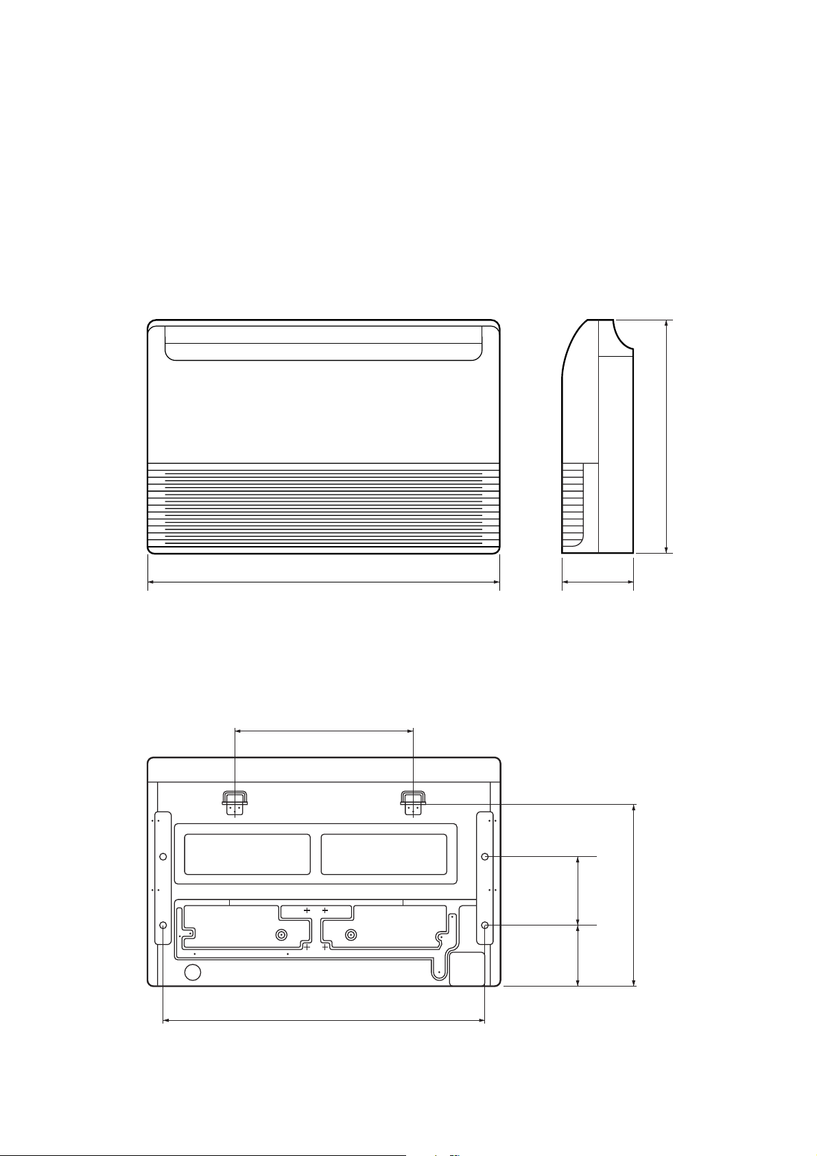
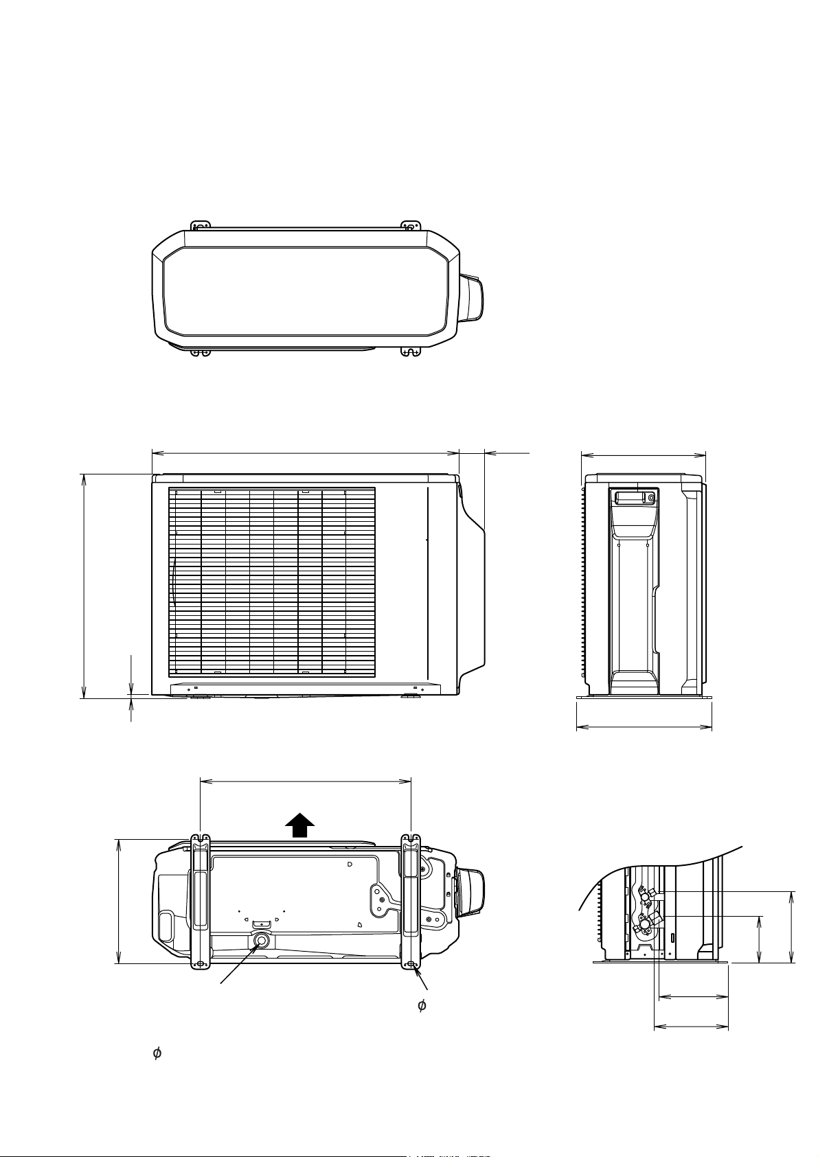
OUTLINE AND DIMENSIONS
INDOOR UNIT
Unit : mm
655
(rear view)
990
500
199
200175
530
900
2006.10.16 2
Page 4
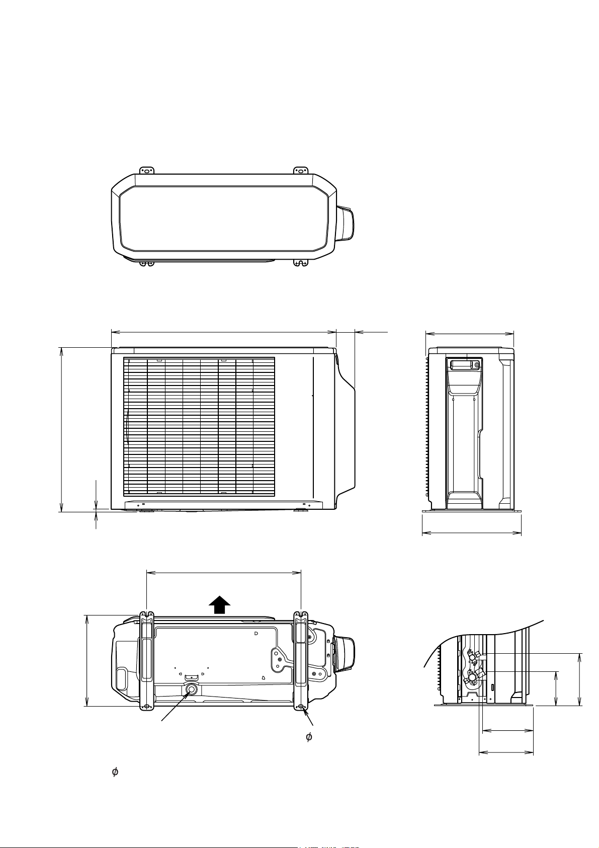
OUTDOOR UNIT
AOHA18LA_L
Unit : mm
Top view
790
66
300
578
10
347
Front view
Side view
540
Air flow
320
Drain pipe
Bottom view
4- 10mm hole
mounting place
( 20)
2008.07.30 3
184
121
177
189
Page 5
OUTDOOR UNIT
AOHA24LA_L
Unit : mm
Top view
31566790
578
10
347
Front view
Side view
540
Air flow
320
184
121
Drain pipe
Bottom view
4- 10mm hole
mounting place
( 20)
2008.07.30 4
177
189
Page 6
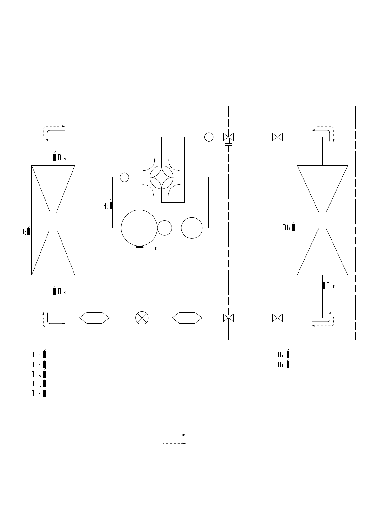
REFRIGERANT SYSTEM DIAGRAM
OUTDOOR UNIT INDOOR UNIT
Muffler
3-Way
valve
Muffler
4-Way
valve
Heat exchanger
Compressor
Expansion
valve
: THERMISTOR (COMPRESSOR)
: THERMISTOR (DISCHARGE)
: THERMISTOR (HEAT EXCHANGER MED)
: THERMISTOR (HEAT EXCHANGER OUT)
: THERMISTOR (OUTDOOR)
Accumulator
StrainerStrainer
Heat exchanger
2-Way
valve
: THERMISTOR (PIPE)
: THERMISTOR (ROOM)
Refrigerant pipe diameter
ABHF18LAT / AOHA18LA_L
Liquid : 1/4" (6.35 mm)
Gas : 1/2" (12.70 mm)
ABHF24LAT / AOHA24LA_L
Liquid : 1/4" (6.35 mm)
Gas : 5/8" (15.88 mm)
2008.07.30
Refrigerant direction
Cool
Heat
5
Page 7
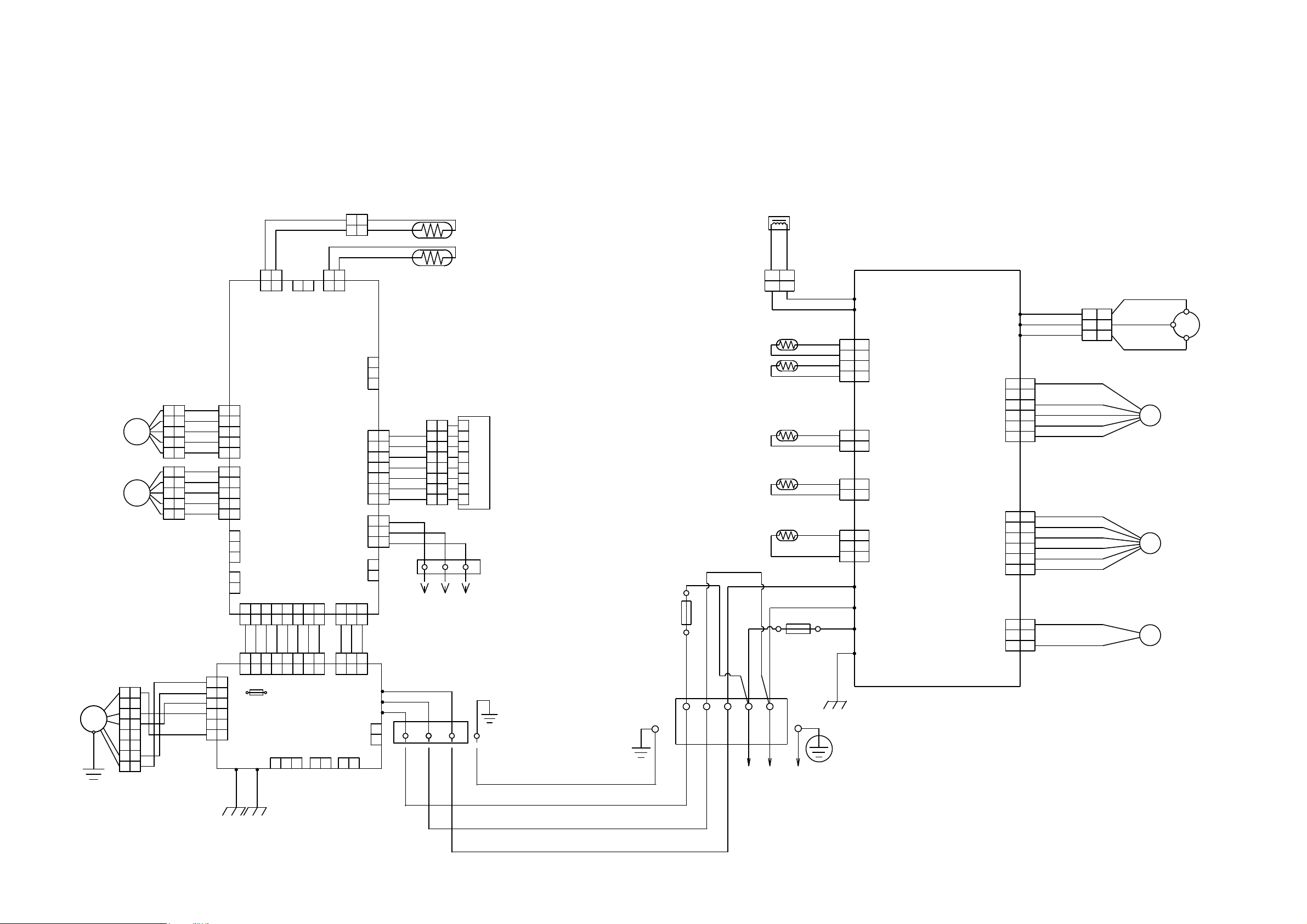
CIRCUIT DIAGRAM
INDOOR UNIT OUTDOOR UNIT
STEP MOTOR
STEP MOTOR
FAN MOTOR
F M
GREEN /
YELLOW
WHITE
REACTOR
YELLOW
YELLOW
12
2
1
FUSE 250V 20A
BLACK
N
WHITE
RED
BLACK
BLACK
BROWN
BROWN
BROWN
BROWN
BLACK
BLACK
BLACK
BLACK
WHITE
BLACK
RED
GREEN
W10
W11
1
1
2
2
CN71
3
3
4
4
121
CN73
2
CONTROLLER PCB ASSY
121
1
2
3
2
1
2
3
W4
W2
W1
W3
( MAIN PCB )
CN72
CN70
RED
W7
W8
W9
CN801
CN40
CN30 4-WAY VALVE
RED
WHITE
BLACK
RED
1
1
2
2
BLACK
3
3
WHITE
4
4
YELLOW
5
5
BLUE
6
6
RED
1
1
BROWN
2
2
BLUE
3
3
ORANGE
4
4
YELLOW
5
5
WHITE
6
6
BLACK
1
1
2
2
BLACK
3
3
1
1
2
3
WHITE
2
3
BLACK
R (R)
COMPRESSOR
C M
S (S)
C (T)
F M
FAN MOTOR
EXPANSION VALVE
PMV
4WV
1
1 2
CN5
BLACK
BLACK
2
1
CN7
2
1
1
2
2
CN8
GRAY
1
1
GRAY
2
2
BLACK
BLACK
THERMISTOR
( PIPE TEMP. )
THERMISTOR
( ROOM TEMP. )
THERMISTOR ( PIPE TEMP . )
1
2
CN3
3
BROWN
1
1
2
2
ORANGE
3
M
M
1
1
2
2
3
3
4
4
5
5
6
6
7
7
8
8
3
4
4
5
5
1
1
2
2
3
3
4
4
5
5
BROWN
YELLOW
WHITE
BLACK
YELLOW
WHITE
BROWN
ORANGE
YELLOW
WHITE
RED
RED
RED
1
2
3
4
5
6
1
2
3
4
5
1
2
3
4
5
1
2
3
4
5
6
E101
1
2
3
CN12
4
5
1
CONTROLLER
2
3
4
5
1
2
3
1
2
CN105
PCB ASSY
CN11
( MAIN PCB )
CN9
CN10
CN4
3 4 5 6 7 8
1 2
3 4 5 6 7 8
1 2
GRAY
GRAY
GRAY
4 567
3
1 2
4 567
3
1 2
F101
FUSE
GRAY
CN104
3.15A 250V
E102
1 2
GRAY
GRAY
GRAY
GRAY
8
8
POWER
SUPPLY
PCB ASSY
CN103
1 2
3
CN1
2 3
1
2 3
1
GRAY
GRAY
2 3
1
2 3
1
CN101
W105
W102
W101
CN108CN102
1 2
1
1
RED
1
1
ORANGE
2
2
YELLOW
3
3
WHITE
4
4
BLUE
5
5
PURPLE
6
6
GRAY
7
7
RED
1
1
WHITE
2
2
BLACK
CN14
3
3
1
2
2
2
3
3
3
4
4
4
5
5
5
6
6
6
7
7
7
8
8
8
TERMINAL
1
2
CN6 CN13
1 2 3
TO REMOTE CONTROL UNIT
( OPTION )
GRAY
CN106
1
2
RED
WHITE
BLACK
1
TERMINAL
2
3
INDICATOR PCB ASSY
THERMISTOR ( DISCHARGE PIPE TEMP. )
THERMISTOR ( COMPRESSOR TEMP. )
THERMISTOR ( PIPE - MID. TEMP. )
THERMISTOR ( OUTDOOR TEMP. )
FUSE 250V 5A
BLACK
BLACK
TERMINAL
2
1 3 L
( N )
POWER SOURCE
GREEN
GREEN
2008.06.26 6
Page 8
OUTDOOR UNIT
DC FAN MOTOR
F M
INDOOR PCB CIRCUIT DIAGRAM
CONTROL UNIT
ABHF18LAT : EZ-0070MHSE
ABHF24LAT : EZ-0070PHSE
UL1015 AWG20 RED
3
UL1015 AWG20 WHITE
2(N)
UL1015 AWG20 BLACK
1
TERMINAL BOARD
W101
W102 W105
UL1015
AWG16
GREEN
E101
UL1015
AWG16
GREEN
E102
POWER SUPPLY PCB ASSEMBL
K06AL-0600HSE-P0
B5P6-VH-B
1
2
3
4
5
6
7
8
EMI FILTER
ZCAT2132-1130
1 T
B2P3-VH-B-E
DRAIN PUMP
B2B-XH-AM
E I B OUT
B3B-XH-AM
E I B I N
CN105
BLACK
WHITE
YELLOW
BROWN
CN106
CN103
CN102
CN105-6
RED
CN105-5
CN105-4
CN105-3
CN105-2
CN105-1
CN106-1
CN106-2
CN103-1
CN103-2
CN102-1
CN102-2
CN102-3
CN104-1
CN104-2
CN104-3
CN104-4
CN104-5
CN104-6
CN104-7
CN104-8
CN101-1
CN101-2
CN101-3
POWER DRIVE
CN104
B08B-PASK-1
GRAY
GRAY
GRAY
GRAY
GRAY
GRAY
GRAY
GRAY
DC SUPPLY
CN101
B03B-PASK-1
EMI FILTER
ZCAT1518-0730
1 T
B06B-XASK-1-A
FLASH
B06B-PASK-1
SP PCB
B02B-PAOK-1
HEATER
B08B-PASK-1
B03B-PASK-1
GRAY
GRAY
GRAY
B03B-XARK-1-A
FLOAT SWITCH
CN15
CN15-1
CN15-2
CN15-3
CN15-4
CN15-5
CN15-6
CONTROLLER PCB ASSEMBLY
( MAIN PCB )
ABHF18LAT : K06AK-0705HSE-C1
ABHF24LAT : K06AK-0706HSE-C1
CN3
CN3-1
CN3-2
CN3-3
CN3-4
CN3-5
CN3-6
CN10
CN10-1
CN10-2
CN4
CN4-1
CN4-2
CN4-3
CN4-4
CN4-5
CN4-6
CN4-7
CN4-8
CN1
CN1-1
CN1-2
CN1-3
CN9
CN9-1
CN9-2
CN9-3
CN8-1
CN8-2
CN7-1
CN7-2
CN5-1
CN5-2
CN13-1
CN13-2
CN13-3
CN13-4
CN13-5
CN13-6
CN13-7
CN14-1
CN14-2
CN14-3
CN6-1
CN6-2
CN2-1
CN2-2
CN2-3
CN2-4
CN2-5
CN11-1
CN11-2
CN11-3
CN11-4
CN11-5
CN12-1
CN12-2
CN12-3
CN12-4
CN12-5
CN8
B2B-XASK-1-A
BLACK
BLACK
CN7
B2B-XAYK-1-A
CN5
B2B-XAKK-1-A
GRAY
GRAY
UL1430 AWG24 x 2
CN13
B07B-PASK-1
1
RED
2
ORANGE
3
YELLOW
4
WHITE
5
BLUE
6
PURPLE
7
GRAY
8
CN14
B3B-XAKK-1-A
UL1430 AWG22 RED
UL1430 AWG22 WHITE
UL1430 AWG22 BLACK
CN6
B02B-PAMK-1
FRESH AIR
CN2
B5P-SHF-1AA
TEST
CN11
B05B-XASK-1-A
BROWN
RED
ORANGE
YELLOW
WHITE
BROWN
RED
ORANGE
YELLOW
WHITE
CN12
B05B-XARK-1-A
THERMISTOR ( ROOM TEMP. )
THERMISTOR ( PIPE - ENTRANCE TEMP. )
BLACK
BLACK
THERMISTOR ( PIPE - MID. TEMP. )
INDICATOR PCB ASSEMBLY
K04EI-0800HSE-D0
CN201
S08B-PASK-2
1
2
3
4
5
6
7
8
EARTH
CN201-1
CN201-2
CN201-3
CN201-4
CN201-5
CN201-6
CN201-7
CN201-8
3 2 1
TERMINAL BOARD
REMOTE CONTROL UNIT
LOUVER ( UP / DOWN )
M
LOUVER ( RIGHT / LEFT )
M
2008.07.30 7
Page 9
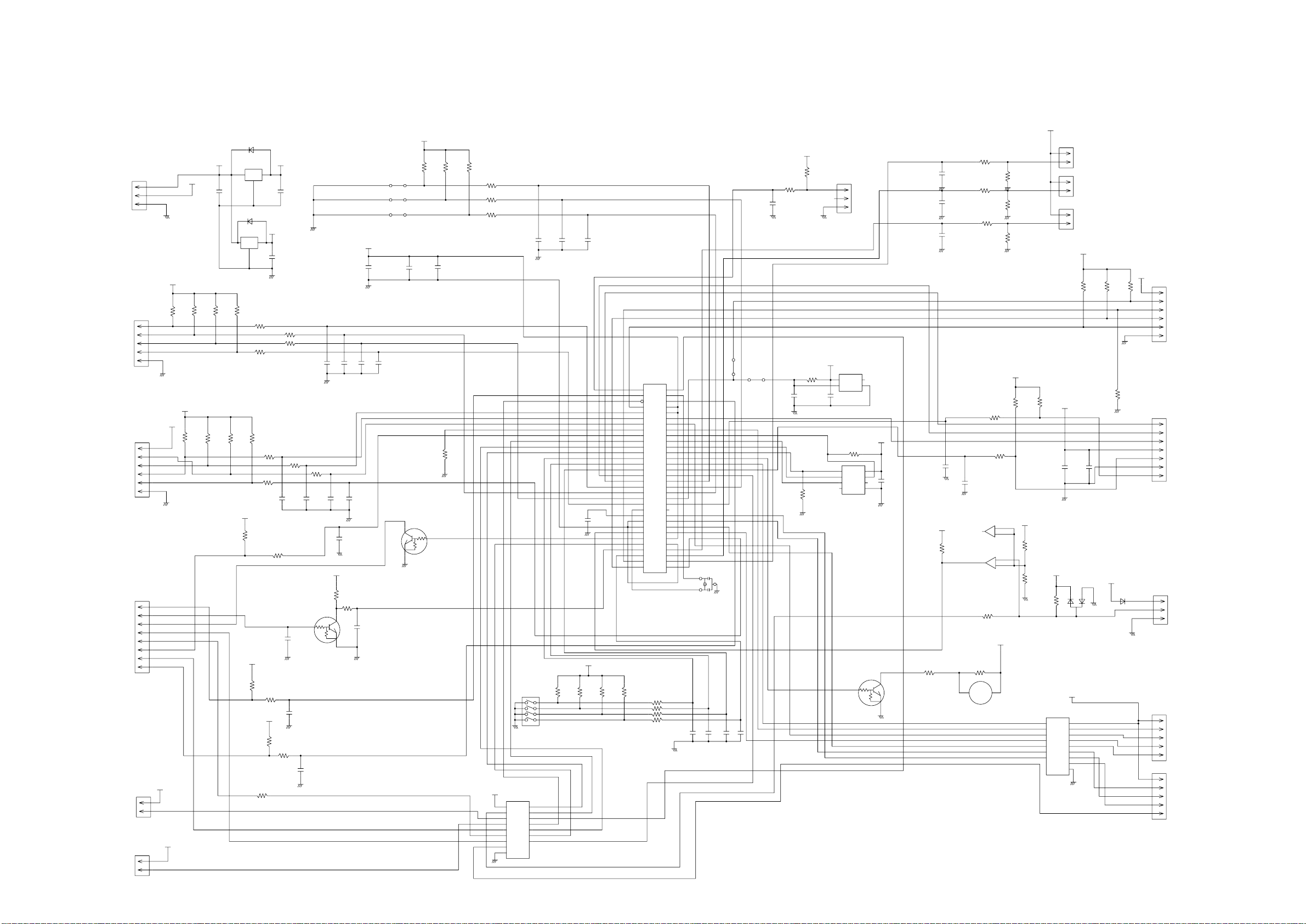
INDOOR UNIT
CONTROLLER PCB ASSEMBLY ( MAIN PCB )
ABHF18LAT : K06AK-0705HSE-C1
ABHF24LAT : K06AK-0706HSE-C1
D4
1SS355
I C8
O
I
G
2
D1
I C2
3
O
I
G
2
1.0K <1/10W> x 4
5V
R19
R22
12V
C3
0.01
<F>
CUSTOM CODE
C2
+
10/
CUSTOM CODE
50V
HEATING FAN DELAY
5V
C32
+
100/
6.3V
R20
R21
C4 - C7
0.01 <F> x 4
CN1
B03B-PASK-1
DC SUPLLY
CN2
B5P-SHF-1AA
TEST
13.5V
NJM7812
1
2
3
5V
50V
1 3
C1
+
10/
1SS355
NJM7805
1
R15 - R18
5V
10K <1/10W> x 4
1
2
3
4
5
5V
10K <1/10W> x 3
13.5V
R23
<1/10W>
R26
10K
R32
R67 1.0K
<1/10W>
5V
1.0K <1/10W> X 3R63
R64
C35 C12 C11
1000P <R> x 3
R25
1.0K
<1/10W>
R65
C14
1000P
<R>
C37
0.1
<F>
CN3
B06B-PASK-1
SP PCB
1
2
3
4
5
6
R24
R66
5V
R29
R28
390
10K
<1/10W>
R34
1.0K
C15
0.01
<F>
C17
0.01
<F>
<1/10W>
1
Q1
DTC124EKA
C18
0.01
<B>
3
C16
0.01
<F>
2
CN4
B08B-PASK-1
POWER DRIVE
CN6
B02B-PAMK-1
FRESH AIR
CN10
B02B-PAOK-1
HEATER
1
2
3
4
5
6
7
8
13.5V
1
2
1
2
13.5V
R30
10K
<1/10W>
<1/10W>
5V
<1/10W>
R33
10K
R27
330
<1/10W>
R31
10K
5V
<1/10W>
2008.07.30 8
JM1
JM2
JM3
C33
0.1
<F>
<1/10W>
Q3
DTC124EKA
3
2
5V
R1 - R3
10K <1/10W> x 3
C28
0.1
<F>
R70
10K
1
R4 - R6
1.0K <1/10W> x 3
SW1
CFS-0402MC
8
7
6
5
13.5V I C3
uLN2003ADR
9
SK
I 1
16
O1
I 2
O2
15
I 3
14
O3
I 4
13
I 5
O4
12
O5
I 6
I 7
11
O6
10
O7
8
GND
1
2
3
4
5
6
7
C8 - C10
0.1 <F> x 3
4
3
2
1
C36
0.47
<F>
5V
I C1
uPD78F0535
34
AVREF
39
I C
RST
36
43
P00
44
P01
P02
45
46
P03
33
P10
32
P11
31
P12
30
P13
29
P14
28
P15
27
P16
26
P17
18
P20
19
P21
20
P22
21
P23
22
P24
P25
23
P30
11
12
P31
13
P32
14
P33
38
XT1
37
XT2
41
X1
X2
40
AGND
25
9
GND0
42
GND1
R11 - R14
10K <1/10W> x 4
R7 - R10
1.0K <1/10W> x 4
AVDD
VDD0
VDD1
35
10
24
15
P34
16
P35
P36
17
57
P40
58
P41
59
P42
P43
60
P44
61
62
P45
63
P46
64
P47
P50
1
2
P51
3
P52
4
P53
5
P54
6
P55
P56
7
8
P57
53
P64
54
P65
55
P66
56
P67
47
P70
48
P71
49
P72
P73
50
51
P74
52
P75
3
2
1
X1
5.00MHz
<CSTS>
C19 - C22
0.1 <F> x 4
JM5
0R0
JM6
0R0
C31
0.01
<F>
<1/10W>
R46
1.0K
<1/10W>
C27
0.1
<F>
R37
10K
<1/10W>
R45
10K
<1/10W>
5V
R56
100K
0.1 <F>
C38
FLOAT SWITCH
CN9
B03B-XARK-1-A
1
2
3
5V
I C7
S80842
2
3
NC
VDD
1
4
OUT GND
R40
10K
<1/10W>
1
CS
VCC
2
SK
DO
3
D I
NC
6
GND
NC
I C5
BR93L56RF-WE2
DTC124EKA
1
5V
ROOM TEMP. TH.
1
CN8
2
C25
50V
12V
R48
10K
1
2
3
4
5
6
7
10/
I C4
1
2
1
2
5V
+
GND
DAN217U
1 2
3
13.5V
9
SK
O1
16
15
O2
14
O3
O4
13
12
O5
11
O6
10
O7
8
B02B-XASK-1-A
PIPE TEMP. TH. ( ENT )
CN7
B02B-XAYK-1-A
PIPE TEMP. TH. ( MID )
CN5
B02B-XAKK-1-A
5V
R49 - R51
10K <1/10W> x 3
R52
10K
<1/10W>
C26
0.01
<F>
D2
12V
D3
D1FS4A
FLASH
CN15
5V
B06B-XASK-1-A
1
2
3
4
5
6
INDICATOR
CN13
B07B-PASK-1
1
2
3
4
5
6
7
CN14
B03B-XAKK-1-A
REMOTE CONTROL UNIT
1
2
3
CN11
B05B-XASK-1-A
LOUVER ( UP / DOWN )
1
2
3
4
5
1
2
3
4
5
CN12
B05B-XARK-1-A
LOUVER ( RHIGT / LEFT )
C29
0.1
<F>
C30
0.1
<F>
C34
0.1
<F>
NC
R57
1.0K
<1/10W>
R58
1.0K
<1/10W>
R62
1.0K
<1/10W>
R41 1.0K
<1/10W>
R43
10K
<1/10W>
R59
10K
<1/10W>
R60
49.9K
<1/10W>
R61
49.9K
<1/10W>
5V
<1/10W>
R44
10K
5V
C23
8
C13
4
0.1
7
5
<F>
0.01
<F>
5V
R55
10K
<1/10W>
Q2
3
2
R36
0R0
PKM13EPYH-4000-A0
C24
1000P
<R>
7
BA10393F
1
BA10393F
R47
390
<1/10W>
R35
1.0K
<1/10W>
B Z
BZ1
R42
47
<1/10W>
6
-
5
+
I C6-2
2
-
3
+
I C6-1
13.5V
12V
R54
15.4K
<1/10W>
R53
28K
<1/10W>
<1/10W>
uLN2003ADR
1
2
3
4
5
6
7
I
I
I
I
I
I
I
Page 10
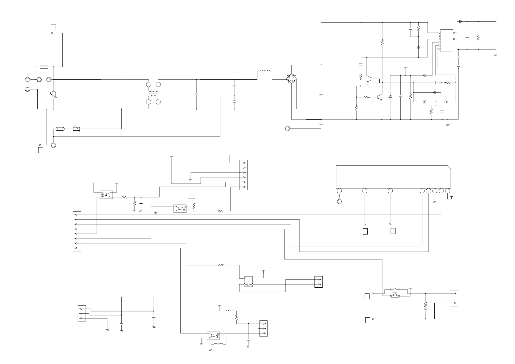
W101
BLACK
W102
WHITE
L
I C26-14
F101
BET 3.15A - 250V
FH101
FH102
VA101
470V
<TNR>
RA-362M
PFC5000-0702F
x 2
VA102
SA101
470V
<TNR>
INDOOR UNIT
POWER SUPPLY PCB ASSEMBLY
K06AL-0600HSE-P0
LF101
ELF17N015A
1
2
C104
0.47
<R46>
4
3
C105
0.01
<YE>
C106
0.01
<YE>
L101
REP28-15
15mH, 1.1A
E102
GREEN
<RS-2W>
C108
4700P
D102
1SR139-600
15V
+
R110
10K
<1/10W>
R103
62K
ZFT22B03-C
2
3
5
6
7
8
D106
D1FL20U
C110 0.047 <ECQB>
D103
D1FL20U
D104
MTZJ5.1B
R109
330
<1/4W>
T101
D105
D1FL20U
C111
100/
+
25V
D108
D2FL20U
12
C113
10
1000/
A
25V
C114
0.01
<KH>
C115
0.01
<KH>
R108
100
<1/2W>
13.5V
R111
+
10K
<1/10W>
340V
<ECQP>
R104
330K
<2W>
C109
220P/
2.0kV
R105
1.5
75
Q101
2SC5354
2
3
2SC1815
R107
100
<1/10W>
1
Q102
1
2
3
D107
RD16M
<B1>
C112
330/
25V
D101
1
D3SB60
3
2
4
C107
100/
450V
+
<ECKE>
<RS-2W>
R106
<RS-2W>
C118
0.01
<KH>
I C26-10
2008.04.14 9
E101
N
GREEN
POWER DRIVE
SERIAL I N
SERIAL I NT
SERIAL ON
DRAIN PUMP
DC FAN-OUT
DC FAN-FEEDBACK
EX. SIGNAL-OUT
EX. SIGNAL-I N
DC SUPPLY
CN104
B08B-PASK-1
CN101
B03B-PASK-1
CN105
<1/4W>
<1/10W>
I C101
<GB>
L103
BLm18
<AG601>
R115
6.8K
R113
330
5V
340V
L102
BLm18
<AG601>
1
2
B5P6-VH-B
6
5
4
3
2
1
G5NB-1A
4
2
R112
330
<1/10W>
DC FAN MOTOR
K101
1
3
3
2
1
C116
0.01
<B>
13.5V
CN102
B3B-XH-AM
15V
<GB>
15V
1
A
R114
4.7K
<1/10W>
4
3
TLP621
5V
1
2
3
4
5
6
7
8
1
2
3
1
2
I C104
TLP621
<GB>
15V
4
3
R116
1.0K
<1/4W>
R117
<1/4W>
5V
C121
0.1
<F>
820
+
C117
100/
25V
AA
13.5V
C120
0.1
<F>
I C103
TLP621
4
3 2
CN103
B2B-XH-AM
2
1
W105
RED
SERIAL
I C 1 0 5
H I 2 0 0 2 R 2
13.5V
RC101
120/0.2
5 4
5 4 3 2
3 2 1
1
5V
CN106
B2P3-VH-B-E
2
1
DRAIN PUMP
IC26-10
101418
6
N
K102
G5NB-1A
342
1
8
7
IC26-14
L
IC26-14
L
IC26-10
N
Page 11

INDOOR UNIT
INDICATOR PCB ASSEMBLY
K04EI-0800HSE-D0
5V
TO MAIN PCB
( ORERATE )
( TIMER )
( LOUVER )
( 5V )
( REMOTE SIGNAL )
( GND )
( MANUAL AUTO SWITCH )
CN201
08 / 08 JC25 / XMR
1430 L=200
BROWN
RED
ORANGE
YELLOW
WHITE
BLUE
PURPLE
GRAY
R202 220
<1/4W>
R203 390
1
2
3
4
5
6
7
8
<1/4W>
R204 560
<1/4W>
3
1
4
2
SW201
EVQPAG04K
D206
EMPG3863X-J300K GREEN
D207
EMAA3863X-J300K ORANGE
D208
EBR3864X-J300K RED
C202
+
10/
25V
C201
0.1
<F>
PHA201
PIC-37143TH5
2
VCC
OUT
1
3
GND
JM201
2008.06.26 10
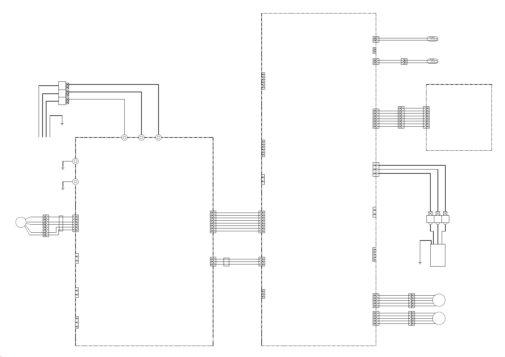
Page 12

OUTDOOR PCB CIRCUIT DIAGRAM
INVERTER ASSY
AOHA18LA_L : EZ-0069HUE
AOHA24LA_L : EZ-006AHUE
TO INDOOR UNIT
POWER SOURCE
AC220 - 240V
50Hz
SERIAL
L
N
1
2
3
4
5
TERMINAL
W103
UL1015 AWG20
BLACK
W100
UL1015 AWG20
WHITE
EMI FILTER
ATFC-25-15-12
2 TURN
5A - 250V
W102
UL1015 AWG20 BLACK
W101
BLACK
UL1015
AWG14
F202
F201
20A - 250V
DISCHARGE TH.
OUTDOOR TH.
EMI FILTER
ATFC-25-15-12
2 TURN
PIPE TH.
EMI FILTER
ATFC-25-15-12
1 TURN
EARTH
UL1015 AWG14
BLACK
UL1015 AWG14
WHITE
UL1015 AWG20
UL1015 AWG16
GREEN
BLACK
BLACK
BROWN
BROWN
BLACK
BLACK
REACTOR
B
W1
( A-1 )
B
W2
( B-1 )
B
W4
RED
( D-1 )
B
W3
( C-1 )
1
CN71
2
B04B-PASK-1
3
WHITE
4
1
CN70
2
B03B-PASK-1
WHITE
3
UL3271 AWG16
WHITE
UL3271 AWG14
RED
W10 W11
B B
CONTROLLER PCB ASSEMBLY
AOHA18LA_L : K06AX-0600HUE-C1
AOHA24LA_L : K06AX-0601HUE-C1
CN30
B2P3-VH-B-C
BLACK
CN801
B5P6-VH-B-L
WHITE
W7
B
W8
B
B
W9
1
2
3
1
2
3
4
5
6
U
RED
V
WHITE
W
BLACK
UL3271 AWG16 x 3
BLACK
BLACK
RED
BLACK
WHITE
YELLOW
BROWN
EMI FILTER
RED
WHITE
BLACK
4-WAY VALVE
F M
COMPRESSOR
C M
DC FAN MOTOR
COMPRESSOR TH.
PIPE ( MID ) TH.
BROWN
BROWN
BLACK
BLACK
CN73
1
B02B-XAMK-1-A
2
GREEN
1
CN72
B02B-XH-AM
2
WHITE
2008.07.30 11
CN40
B6B-XARK-1-A
1
2
3
4
RED
5
6
RED
BROWN
BLUE
ORANGE
YELLOW
WHITE
EXPANSION VALVE MOTOR
M
Page 13

OUTDOOR UNIT
CONTROLLER PCB ASSEMBLY
AOHA18LA_L : K06AX-0600HUE-C1
AOHA24LA_L : K06AX-0601HUE-C1
5V
R23
27K
4.7K
1
2
3
4
5
6
7
8
3
2
3
2
1%
W10
WHITE
R1
PFC / 58P
MAKING OF
CURRENT
DIRECTIVE
R21
10K
<1/10W>
R22 1.0K
<1/10W>
R147
R148
C123
2200P
<B>
CTDW / 34P
C14
0.1
<F>
V4-AC / 27P
V4-DC / 29P
ACFAN / 28P
REACTOR
W11
RED
W5
ORANGE
W6
ORANGE
4
PR / I C80-5
1
R157
4.7K
C138
2.2/
50V
DAN217U
4
1
R20 1.0K <1/10W>
C21
0.047
<B>
R150R151
195K <RN-1/2W> 1% x 4
15V
D110
DAN217U
2 1
3
1
2
D111
3
DAN217U
-12V
R144
22K
1%
R145
22K
1%
C124
2200P
<B>
R152
4.7K
1%
LED / 30P
SO / 32P
PR / 31P
CONTROL GND
D100
LL25XB60
2
3
LL25XB60
2
3
D101
1
+
4
-
1
+
4
-
15V
2 1
D105
3
-12V
C137
R155
0.1
<F>
R156
+
100K
1%
x 2
ZXL / 37P
S I / 48P
C20
0.1
<F>
DTC143EUA
Q103
DTC143EUA
2
PFCEN / 14P
15V
C130
0.1
<F>
R160
R159
4.7K
R161
C129
1000P
<B>
R143
39K
1%
9
-
8
10
+
I C104-3
BA2902F
R146
39K
1%
AC WAVEFORM DETECTION
FAN IN / 17P
FAN PWM / 2P
PFCSW / 35P
CT / 3P
TEST / 59P
PFC / 58P
TTXD / 60P
TAUX3 / 21P
CTDW / 34P
CP-POS / 47P
V4-AC / 27P
ACFAN / 28P
V4-DC / 29P
LED / 30P
PR / 31P
SO / 32P
IPM-TRIP / 33P
E2CS / 41P
EPV2 / 42P
EPV4 / 43P
EPV3 / 44P
TH / 10P
IPM-CR / 9P
DCV / 8P
ACV / 7P
TA / 6P
TE / 5P
TD / 4P
C500
0.1
<F>
R400 - R407
0.2 <1W> 1% x 8
10K 1% x 2
R127
R153
6
-
5
+
I C3-2
BA4560
R154
120K
Q102
5V
68K
1%
1%
7
R142
1.2K
1%
5V
<1/10W>
R132
2.2K
2
3
1
R162
3
2
I C105-1
BA2903F
R128
R131
68K
1%
+
-
10
1
120K 1%
1.5K
R137, R136 10K 1% x 2
R138 10K 1%
R140
10K
1%
R139
10K
1%
1
D109
RB751V
6
-
5
+
I C104-2
BA2902F
FULL WAVE RECTIFICATION
I C500
MB90462
17
P63
VCC
AVCC
P62
16
2
P00
P46
35
P12
P01
P17
3
P50
P13
P37
59
P36
58
P14
60
P40
P15
21
P16
MD2
34
P11
AVR
47
P26
P24
27
P02
P25
P03
28
P30
29
P04
P31
30
P05
P32
P06
31
P33
32
P07
P34
P10
33
P35
57
P60
C
P20
41
P61
42
P21
MD0
P22
MD1
43
P23
P44
44
10
P57
P43
P42
9
P56
P55
P41
8
7
P54
P45
RSTX
5
P52
P53
6
P27
AGND
P51
4
22
X0
GND
X1
23
GND
3
X500
8.00MHz
2
<CSTLS>
CURRENT DETECTION
R130
220
1%
3
1
5V
R163
10K
1%
ZXH / 36P
6
-
5
+
I C105-2
BA2903F
7
D108
RB751V
56
11
25
26
40
36
37
38
39
12
45
46
50
51
52
53
54
55
14
15
18
20
64
63
62
61
1
19
48
13
24
49
C502
R126
100K
1%
I C103-1
BA4560
2
-
3
+
R129
100K
1%
2
-
3
+
I C3-1
BA4560
C117
1.0
<B>
7
R135
10K
1%
R141
10K
R500
10K
0.1
<F>
1
1
PFC CONTROL
RB751V
ZWRO-CROSS
DETECTION
( HIGH-SPEED )
R134
10K
2
3
I C104-1
BA2902F
1%
R502
1.0K
C503
0.1
<F>
+
C501
10/25V
15V
BYPASS CAPACITOR
C119, C120
0.1 <F>
x 2
-12V
6
7
-
5
+
1% x 2
R166 3.9K
R158 3.9K
1 12
D115
DAN217U
D107
R133
10K
1%
-
1
+
13
-
12
+
I C104-4
BA2902F
5V
C561
0.01
<F>
C139
2.2/
50V
I C103-2
BA4560
R122
R123
4.7K
3
3
D114
DAN217U
R118
10K
1%
R119
10K
1%
4700P
R164
22K
1%
14
R503
10K
SERVICE
JM500
TAUX / 25P
E2SK / 40P
ZXH / 36P
ZXL / 37P
E2DI / 39P
EPV1 / 45P
PFC-TRIP / 46P
U / 50P
X / 51P
V / 52P
Y / 53P
W / 54P
Z / 55P
PFCEN / 14P
TMODE / 18P
MD1 / 64P
MD2 / 63P
TCK / 62P
TRXD / 61P
MDO / 1P
/ TRES / 19P
S I / 48P
R561
1.0K
LINE FILTER
POWER SOURCE
AC230V
50Hz
EARTH
SERIAL
B2P3-VH-B-C
4-WAY VALVE
CN801
B5P6-VH-B-L
FAN MOTOR
CN40
B06B-XARK-1-A
EXPANSION VALVE
CN73
B02B-XAMK-1-A
COMPRESSOR TH.
CN72
B2B-XH-AM
PIPE ( MID ) TH.
CN71
B04B-PASK-1
PIPE TH.
DISCHARGE TH.
CN70
B03B-PASK-1
OUTDOOR TH.
2008.07.30 12
L
BLACK
N
WHITE
GREEN
RED
4-WAY VALVE DRIVE
CN30
WHITE
RED
GREEN
W1
VA1
470V
<TNR>
VA2
470V
<TNR>
W2
SA1
RA-302M
W3
8 7 1
W4
SERIAL COMMUNICATION
1
3
2
=
POW-GND
15V
L800
BL02Rn1
C802
0.1
<F>
DC-F
1
2
3
4
5
6
12V
L40
1
2
3
4
5
6
1
2
R10 4.75K
1%
1
2
1
L70 BL02Rn1
2
3
4.75K 1%
4
1
2
3
C75
0.1
<F>
R73
38.3K
1%
C1
1.0
<LE>
CR30
RE1201
0.1/120
C800
100/
25V
+
POW-GND
DC FAN MOTOR COMMUNICATION CIRCUIT
I C40
TD62064
2
O1
7
O2
9
O3
16
O4
GND1
4
5
GND2
12
GND3
13
GND4
R13
10K
R12
R11
13K
10K
1%
5V
TEMPERATURE SENSING CIRCUIT
R71
R75
10K
R76
R72
10K
13K
1%
R77
10K
RCH4716
1
4
H Y I C 1
G K - 3 0 4 3 4 E
101418
R801
1.0K
<1/4W>
R802
5V
560
<1/4W>
R803 10K
<1/10W>
12V
3
I 1
6
I 2
11
I 3
14
I 4
1
COM1
8
COM2
10
NC1
C40
15
NC2
0.1
<F>
C10
0.1
<F>
C71
0.1 <F>
C72
0.1
<F>
C73
0.1
<F>
L1
2
3
6
5V
JM32
JM31
15V
Q801
DTA143EUA
1
2
3
5V
2
1
3
EXPANSION VALVE CONTROL
R40 - R43
1.5K <1/10W> x 4
5V
R14
2.2K
1%
R17
R16
22K
22K
1%
1%
TH / 10P
C11
0.1
<F>
TE / 5P
SLR-332VR
TD / 4P
TA / 6P
C4
0.01
<KH>
C5
0.01
<KH>
5 432 1
5
4
K30
FTR-F3
2
1
12V
3
4
V4-AC / I C80-3P
Q800
DTC143EUA
3
1
D600
DAN217U
R804
1.0K
EPV3 / 44P
EPV4 / 43P
EPV2 / 42P
EPV1 / 45P
I C10-1
C12
BA2903F
0.1
<F>
6
-
5
+
I C10-2
BA2903F
12V
D80
<RED>
SO / I C80-2P
V4-AC / I C80-3
V4-DC / I C80-4
PR / I C80-5
ACFAN / I C80-6
C6
3.3
<LE>
G5NB-1A
3
2
SO / I C80-2P
JM30
FAN PWM / 2P
2
FAN IN / 17P
C801
0.01
<F>
15V
3
+
1
2
-
7
R80
2.2K
12V
K33
5V
R18
10K
C13
0.1
<F>
LED INDICATOR
I C80
uLN2003
1C
16
2C
15
14
3C
4C
13
12
5C
11
6C
10
7C
9
COM
RUSH CURRENT
PREVENTION
ZPR0RCH400
12V
K1 DW12D1
<1/10W>
R149
R19
1.0K
1B
2B
3B
4B
5B
6B
7B
8B
E
5V-2
+
R121
100K
I C102-2
BA2901F
7
6
C113
2700P
<B>
2
C111
<B>
C125
0.1
<F>
15V
-12V
R560
100K
GT30J122
5V
L130
ELC0607RA
C140
0.1
<F>
1%
1
+
-
C142
<F>
5V-2
R116
15K
1%
R117
22K
1%
C115
0.1
<F>
C116
0.1
<F>
COMP
5V
2
1
Q100
0.1
5
4
OVER CURRENT
DETECTION
C126
+
2.2/
50V
R168
22K
RESET
VDD
OUTNCGND
I C560
S80842
D102
1NH42
R103
<1/2W>
R102
47K
R120 4.7K 1%
R125 4.7K
11
+
10
I C102-4
BA2901F
R171
4.7K
R115
22K
1%
2
+
I C102-1
BA2901F
R165
22K
C127
C131
3
4
100
1
5V
13
5V-2
2.2/
50V
0.1
<F>
E2CS / 41P
E2SK / 40P
E2DI / 39P
R112
10K
1%
2
C103
0.1
3
<HCP>
GATE DRIVE
<1/4W>
R109 22
R108 47
1 2
GATIN
VCC
S I
5
SO
D I
7
NC
GND
3
I C100
TA8316
R124
4.7K
I C101
TC 74HC00AF
1
1
2
2
3
3
4
4
5
5
6
6
7
7
R101
4.7K
I C102-3
BA2901F
C110
OVER VOLTAGE
0.1
DETECTION
<F>
15V
C128
+
0.1
<F>
R169
22K
C132
C133
+
2.2/
50V
EEPROM
R93, R92, R91, R90
MD0 / 1P
MD1 / 64P
MD2 / 63P
TEST / 59P
C100 - C102
LLQ2W661KEUBGC
660uF / 450V x 3
+ +
+
15V
<1/4W>
6
4
C105
0.1
<F>
PFC-POWER-GND
L100 BL02Rn1
15V-2
C104
CONTROL GND
+
10/
BASE POINT
25V
GATE DRAIVE GND
5V
14
14
13
13
12
12
11
11
10
10
9
9
8
C106
8
C141
1000P
<B>
14
C112
0.1
<F>
5V
2.2/
50V
C572
1.0K
<1/10W>
+
10K x 4
R167
0.1
10K
<F>
5V-2
R113
4.7K
1%
9
+
8
C136
0.01
<F>
R114
15K
1%
I C102
BYPASS CAPACITOR
INPUT CURRENT ( RSM ) AVERAGE DETECTION
3
D112
DAN217U
1 2
AVERAGE OF INPUT VOLTAGE RECTIFICATION
5V
C134
0.1
<F>
1 2
I C570
M93C46
8
VCC
CS1
4
2
SK
DO
3
D I
7
NC
6
NC
GND
5
R570
10K
5V
EXAMPLE OF AOHA18LALL
F100
GDT 250 15
15A - 250V
FSL 250 3.15<EM >
3.15A - 250V
R104
220K
<2W>
PFC5000-0702F
DCV
POW-GND
PFCSW / 35P
PFCEN / 14P
PFC-TRIP / 46P
DCV Ave
5V
D106
DAN217U
3
231
C108
50V
R111
10K
ACV / 7P
2.2/
+
C109
+
2.2/
50V
D113
DAN217U
DC VOLTAGE
DETECTION
R110
6.8K
DCV / 8P
CT / 3P
5V
C570
0.1
<F>
MODEL SWITCHING
JM101
JM102
JM103
JM100 TEST
DCV
F4
FH2
FH1
x 2
DCV-F
POW-GND
R105, R106
195K
<RN-1/2W>
1%
R107
3.83K
U / 50P
1%
V / 52P
W / 54P
X / 51P
Y / 53P
Z / 55P
IPM-TRIP / 33P
C219
1000P
<B>
C107
0.1
<F>
IPM-CR / 9P
REVERSE CURRENT DETECTION CIRCUIT
CP-POS / 47P
COMP
D50
1SS355
D51
UDZS8.2B
L50
BLm21
<AG601>
L51
BLm21
<AG601>
D52
1SS355
R51
C50
47/
35V
POW-GND
D200 - D202
U1JU44 x 3
+
R203 330K
C205 0.1 <F>
C204 47 / 35V
R218
<1/10W>
R204 - R209
390 <1/10W> x 6
R219
1.0K
R220
1.0K
5V
R339
10K
3
1
DCV-F
15V
R52
470K
<1/8W>
1%
R53
510K
<1/8W>
1%
R54
510K
<1/8W>
1%
R55
510K
<1/8W>
1%
47
C51
+
1.0
<B>
SWITCH POWER SUPPLY
POWER-GND
R200
<1/2W>
+
R202 330K
C203 0.1 <F>
C202 47 / 35V
5V
4.7K
D301
DAN217U
2
C320
0.15
<ECQB>
5V
R334
10K
1%
2
Q300
DTC114EUA
C300
100P
<CH>
CONTROL SOURCE
R56
150K
<2W>
UF4005
I C50
TOP243PN
1
M
2
S
3
S
4
C
39
+
R201 330K
C201 0.1 <F>
C200 47 / 35V
C206 - C208, C215 - C217
5V
1
3
R337
100K
I C302-1
BA2903F
1
2200P <B> x 6
PEAKLOAD CURRENT DETECTION
D302 RB751V
C311
1000P
<B>
R327
22K
5V 5V
1%
2
-
3
+
C339
0.01
<F>
5V
R81
1.0K
<1/10W>
7
R83
27K
<1/10W>
C52
2200P
<E>
1
2
3
R57
0R0
4
5
D53
8
S
S
7
5
D
C209 0.1 <F>
IPM-G
R328
1.0K
R335 R336
R338
3.3K
1%
6
-
5
+
I C302-2
BA2903F
T60
RPZ-1F
C210 0.1 <F>
C85
10/
25V
10
9
8
7
6
C211 0.1 <F>
C212 0.1 <F>
R329 47K 1%
I C300-1
BA4560
-
1
+
7
I C300-2
BA4560
R333
10K 1% x 3
C330
1000P
<B>
15V
DAN217U
+
C86
470P
<B>
C84
0.1
<F>
D62
D1FL20U
C66
100/
25V
1SS355
15V
L300
ELC0607RA
D203 HZ24BP-TK-E
C221 0.1 <F>
C222 1.0 <F>
C213
0.022
<F>
IPM-G
R330
2
3
R331
R332
47K
1%
5
+
6
-
VIRTUAL NEUTRAL POINT
D304
DAN217U
221
3 3
C87
330P
<B>
D60
D1FL20U
+
D61
D1FL20U
I C60
BA17805
+
D64
+
C220 47 / 35V
C305
0.1
<F>
4.7K 1% x 2
WVU
R305
R303
R304
R306
D303
C64
330/
25V
D63
1SS355
I
C69
+
100/
25V
-12V
I C200
FSBB20CH60
1
VCC
2
COM
3
I N
4
I N
I N
5
VFO
6
CFOD
7
CSC
8
9
I N
10
VCC
11
VB
12
VS
I N
13
14
VCC
15
VB
16
VS
I N
17
VCC
18
19
VB
20
VS
R210
1.0K
C214
2200P
<B>
IPM-G
15V
C306
0.1
<F>
-12V
R301R302
195K <RN-1/2W>
1
REFERENCE OF
POSITION DETECTOR
R309
5.76K
1%
R310
143
1%
C65
+
470/
25V
OG123
U V
W7 W8 W9
21
NU
22
NV
U V W
23
NW
24
U
25
V
26
W
DCV
27
P
AOHA24LACL is R211 - R216
<1W>
IPM-GND BASE POINT
C67
0.1
<F>
R307, R308
195K
<RN-1/2W>
x 2
R311
8.66K
1%
R61
10K
1% x 6
R211
R212
R213
R214
R215
R216
R217
0.15
1%
x 7
IPM-G
POW-GND
15V
12V
5V
+
C68
100/
25V
W
Page 14

ERROR CONTENTS
INDOOR UNIT
The lamps show the error contents.
: 0.5s ON/0.5s OFF (Flash) : OFF
Operation lamp (Green)
Timer lamp (Orange)
Filter lamp (Red)
Operation
lamp (Green)
2 times
2 times
2 times
2 times
3 times
3 times
3 times
3 times
3 times
3 times
3 times
Timer lamp
(Orange)
2 times
3 times
4 times
5 times
6 times
7 times
8 times
2 times
3 times
4 times
6 times
2 times
3 times
4 times
8 times
Filter lamp
(Red)
2 times
3 times
4 times
Error contents
Serial reverse transfer error at starting up operation
Serial reverse transfer error during the operation
Serial forward transfer error at starting up operation
Serial forward transfer error during the operation
Communication error ( Main PCB Display PCB )
Communication error ( Display PCB Main PCB )
Wired remote control abnormal
Indoor room temperature sensor error
Indoor heat exchanger temperature sensor (middle) error
Indoor heat exchanger temperature sensor (inlet) error
Float switch operated
Outdoor discharge pipe temperature sensor error
Outdoor heat exchanger temperature sensor (outlet) error
Outdoor temperature sensor error
Compressor temperature sensor error
2-way valve temperature sensor error
3-way valve temperature sensor error
Outdoor heat exchanger temperature sensor (middle) error
4 times
5 times
5 times
5 times
5 times
5 times
5 times
6 times
7 times
7 times
7 times
7 times
7 times
8 times
8 times
2 times
2 times
3 times
5 times
6 times
7 times
8 times
2 or 3 times
2 times
3 times
4 times
5 times
6 times
2 or 3 times
4 times
0.1 second flashing
Indoor manual auto switch abnormal
IPM protection
CT error
Compressor location error
Outdoor fan error
Connected indoor unit abnormal
Outdoor unit computer communication error
Indoor fan abnormal
Discharge temperature error
Exessive high pressure protection on cooling
4-way valve abnormal
Pressure switch abnormal
Compressor temperature error
Active filter abnormal
PFC circuit error
Model appreciation error
2008.05.09 13
Page 15

WIRED REMOTE CONTROL
If an error occurs, the following display will be shown.
("EE" will appear in the set room temperature display.)
If "CO" appears in the unit number display, there is a remote control error.
Refer to the installation instruction sheet included with the remote control.
Unit number
Error code
SUMOTUWETH FR
Error code Error contents
01
13
26
27
00
02
04
28
09
0C
06
0A
15
1d
1E
29
20
17
18
1A
1b
1F
1c
12
0F
24
2c
16
2b
19
25
11
Serial reverse transfer error
Serial forward transfer error
Communication error ( Main PCB Display PCB )
Communication error ( Display PCB Main PCB )
Wired remote control abnormal
Indoor room temperature sensor error
Indoor heat exchanger temperature sensor (middle) error
Indoor heat exchanger temperature sensor (inlet) error
Float switch operated
Outdoor discharge pipe temperature sensor error
Outdoor heat exchanger temperature sensor (outlet) error
Outdoor temperature sensor error
Compressor temperature sensor error
2-way valve temperature sensor error
3-way valve temperature sensor error
Outdoor heat exchanger temperature sensor (middle) error
Indoor manual auto switch abnormal
IPM protection
CT error
Compressor location error
Outdoor fan error
Connected indoor unit abnormal
Outdoor unit computer communication error
Indoor fan abnormal
Discharge temperature error
Exessive high pressure protection on cooling
4-way valve abnormal
Pressure switch abnormal
Compressor temperature error
Active filter abnormal
PFC circuit error
Model appreciation error
SA
2008.05.09 14
Page 16

Outdoor unit
Error contents
Thermistor malfunction
Abnormal discharge temperature
Current surge protection
CT abnormality
Compressor position detection malfunction
Fan malfunction
PAM voltage abnormality
Timer short
Compressor temperature protection (permanent stop)
PFC surge protection (permanent stop)
LED
on 0.1 sec / off 0.1 sec
on
on 0.5 sec / off 0.5 sec
on 2.0 sec / off 2.0 sec
on 0.1 sec / off 2.0 sec
on 5.0 sec / off 5.0 sec
on 5.0 sec / off 0.1 sec
on 1.0 sec / off 1.0 sec
on 2.0 sec / off 5.0 sec
on 5.0 sec / off 2.0 sec
2008.07.29 15
Page 17

PARTS
INDOOR UNIT
8
5
3
4
Ref. Description Part number
1 Remote Control 9315885012
2
Remote Control Holder
3 Top Cover 9358534014
4 Arm 9358565001
9305642045
6
4
7
2
5 Hanger Bracket L 9358596005
6 Hanger Bracket R 9358595008
7 Cosmetic Panel R 9358535011
8 Cosmetic Panel L 9358536018
2008.05.09 16
1
Page 18

INDOOR UNIT
Panel assy
13
PCB holder
14
Insulation F
Insulation C
Insulation D
15
Insulation E
11
Ref. Description Part number
11
Panel
9358531112
12 Side Cover R Assy 9359069041
13 Indicator PCB Assy 9705798052
14 Insulation (Panel) A 9358574003
15 Insulation (Panel) B 9358914007
--
Panel Assy(with side cover R
--
Badge 9357914008
9359076193
12
2008.04.16
17
Page 19

INDOOR UNIT
Grille
22
24
25
21
Ref. Description Part number
23
24
21
21 Air Filter 9358567029
22 Grill G 9358533017
23 Arm Bracket 9359281009
24 Grille Support 9358602003
25 Filter Bracket 9358607008
2008.04.16 18
Page 20

33
38
37
INDOOR UNIT
Kit (Flap base)
33
37
39
32
Ref. Description Part number
31 Kit (Flap Base) 9372670019
32 Flap Base 9358537015
33 Protect Cover 9358564004
34 Support Stay 9358599006
35 Louver 9358561010
36 Bushing B 9358554005
37 Louver Stopper 9358555002
36
35
34
31
38 Louver Rod 9358559000
39 Motor Rod 9358560006
2008.04.16 19
Page 21

INDOOR UNIT
Flap base sub assy
41
41
43
42
44
48
52
47
53
45
46
50
51
Ref. Description Part number
41 Bushing 9357942001
42 Bushing C 9358553008
43 Flap (Upper) G 9358539019
44 Kit (Flap Lower) 9372671016
45 Step Motor H 9900297015
46 Louver Link 9358556009
47 Louver Shaft 9358557006
48 Louver Link Cover 9358558003
49 Step Motor-V 9900362010
50 Motor Base 9358562000
51 Motor Rod-A (Step V) 9358550007
52
Flap Link-Upper (Step V)
53
Flap Link-Lower (Step V)
9358551004
9358552001
49
2008.07.29 20
Page 22

INDOOR UNIT
Base assy
62
62
61
Ref. Description Part number
61 Base Assy 9359061014
62 Cap 9358563007
63 Base Bracket 9358586006
62
63
62
2008.04.16 21
Page 23

72
74
75
77
78
73
INDOOR UNIT
Drain pan assy
Evaporator
76
79
71
Ref. Description Part number
71 Kit (Separate Wall A) 9372666012
72 Kit (Separate Wall B) 9373448013
73 Kit (Drain Pan Assy) 9372669013
74 Drain Cap 9358746004
75 Drain Hose Assy 9359242000
76
Kit (Insulation Flap Base)
9372672013
77 Kit (Dew Proof Plate) 9372673010
78 Catch 9359096009
77
79 Pipe Thermistor 9900022020
2008.07.29 22
Page 24

INDOOR UNIT
ABHF18LAT
Evaporator
82
ABHF24LAT
81
81
83
84
84
82
Part number
Ref. Description
ABHF18LAT
ABHF24LAT
81 Evaporator Assy 9362513043 9362513050
82 Bypass Pipe Assy 9377819017 9377821010
8384Distributor Assy 9371325354 9371325361
Coupling Pipe Assy 93730383999373038382
2008.05.09 23
83
Page 25

INDOOR UNIT
Fan motor
93
97
98
93
98
91
94
95
92
Ref. Description Part number
91 Sirocco Fan Assy 9385258006
92 Casing 9358543009
93 Casing Cover 9358544006
94 Fan Motor Assy 9602401017
95 Rubber 9385102002
95
91
96
92
96 Motor Fixing Table 9358591000
97 Protector 9359282006
98 Motor Fixture 9358594001
2008.04.16 24
Page 26

INDOOR UNIT
Control unit
102
103
104
106
101
Ref. Description Part number
101 Control Box 9358600016
102 Control Box Cover Assy 9359097006
103 Controller PCB Assy (18)
9707393347
105
103 Controller PCB Assy (24) 9707393354
9707398014104 Power Supply PCB Assy
105 Terminal 3P 9306489045
106 Terminal 3P 9703345012
-- Room Thermistor Assy 9703299087
2008.04.16 25
Page 27

PARTS
OUTDOOR UNIT
7
9
1
6
3
5
4
8
2
Ref. Description
1 Top Panel Assy
2 Cover (Switch) Assy 9309237032
3 Cabinet Assy
4 Blow Down Grille
5 Cabinet Right Assy
6 Fan Ring
7 Grip
8 Emblem
9 Protective Net
AOHA18LA_L AOHA24LA_L
9309230057
9314809040
9308884015
9309236011
9308885012
9308880017
9315211019
9315319012
Part number
9309230057
9309237032
9314809019
9308884015
9309236028
9308885012
9308880017
9315211019
9315033017
2008.07.30 26
Page 28

OUTDOOR UNIT
17
16
24
18
13
29
25
27
14
19
26
30
20
Ref. Description
AOHA18LA_L AOHA24LA_L
11 4-Way Valve
12 Pulse Motor Valve Assy
13 Condenser Assy
14 Thermistor Spring A
15 Thermistor Spring
16 Propeller Fan
17 Nut
18 Motor Bracket
19 Separator Assy
20 Base Assy
21 3-Way Valve Assy
22 2-Way Valve Assy
23 Expansion Valve Coil
24 Fan Motor
25 Compressor Assy
Thermistor Assy26
27
Heat Exchanger Thermistor
28 Solenoid Coil
9900047016
9311641018
9311382027
313728262708
9300089012
9309909014
9304902003
9308872012
9312971015
9308869081
9970092015
9970093012
9900057039
9602133017
9313763039
9900148027
9900403010
9970033018
29 Compressor Thermistor 9900156046
Reactor Assy
30
9900354015
Outdoor Thermistor-- 9900210045
Condenser Assy B-- --- 9315303011
Part number
9900163013
9315310019
9315302014
313728262708
9357804002
9309909014
9304902003
9308872029
9312971015
9315296030
9315414014
9313062019
9900057039
9602451012
9315297037
9900148027
9900403010
9970055010
9900156046
9900354015
9900210045
15
28
37
11
12
23
22
21
2008.07.30 27
Page 29

OUTDOOR UNIT
31
37
36
35
33
34
32
Ref. Description
AOHA18LA_L
31 Inverter PCB Assy
32 Fuse Holder 0501454012
33 Fuse Holder 0501456016
34 Fuse
35 Fuse 0600372163
Terminal36 9703874031
Inverter Case Assy37 9315690012
9707427011
0600382018
Part number
AOHA24LA_L
9707427028
0501454012
0501456016
0600382018
0600372163
9703874031
9315690012
2008.07.30 28
Page 30

ACCESSORIES
INDOOR UNIT
Name and Shape Part numberApplication
Cosmetic Panel-L
Cosmetic Panel-R
Q'ty
1
1
9358536018
9358535011
Screw (M4 x 10)
Installation template
Hanger bracket (left)
Hanger bracket- (right)
Anchor bolt (M12)
Special nut
Spring washer
Wall bracket
Screw (M4 x 20)
2
For positioning the indoor unit.
For under ceiling type.
1
For suspending the indoor
1
unit from ceiling.
1
4
4
4
For suspending the indoor
2
unit on the wall.
For fixing the wall bracket.
6
0700009037
9359107002
9358596005
9358595008
313806339400
0700007125
9358597002
0700076107
Coupler heat insulator
(large)
Coupler heat insulator
(small)
Nylon fastener
Drain hose
Insulation
(drain
hose)
VT wire
Remote
control
Remote
control
holder
Battery
Screw (M3 x 12)
For indoor side pipe joint.
1
(Large pipe)
For indoor side pipe joint.
1
(Small pipe)
For fixing the drain hose.
1
1
Adhesive type 70 x 230
1
For fixing the drain hose
1
L 280 mm
For air conditioner operation
1
For installing remote control
1
on the wall
For remote control
2
For mounting the remote
control holder
2
9378173552
9378173736
312300787605
9359242000
9359225003
313806350303
9315885012
9305642045
0600185541
0700019098
2008.06.26 29
Page 31

OUTDOOR UNIT
Name and Shape Part numberApplication
Drain pipe
Q'ty
For drain piping work. 9303029015
1
OPTIONAL PARTS
Wired remote control : UTB-GUD (P/N 9077030002)
2008.07.29 30
Page 32

0805G3487
 Loading...