

Page 1
SPLIT TYPE
AIR CONDITIONER
CEILING
type (50Hz)
Models
Indoor unit Outdoor unit
ABHA36LAT
ABHA45LAT
AOHA36LATL
AOHA45LATL
CONTENTS
SPECIFICATIONS
DIMENSIONS
REFRIGERANT SYSTEM DIAGRAM
CIRCUIT DIAGRAM
ERROR CONTENTS
PARTS (INDOOR UNIT)
PARTS (OUTDOOR UNIT)
STANDARD ACCESSORIES
. . . . . . . . . . . . . . . . . . . . . .
. . . . . . . . . . . . . . . . . . . . . . . . .
. . . . . . . . . . . . . . . . . . . .
. . . . . . . . . . . . . . . . . .
. . . . . . . . . . . . . . .
. . . . . . . . . . . . .
. . . . . . . . . . .
. . . . .
. . . . . . .
. . . .
1
2
4
5
7INDOOR PCB CIRCUIT DIAGRAM
10OUTDOOR PCB CIRCUIT DIAGRAM
13
16
21
25
Page 2
SPECIFICATIONS
ELECTRICAL DATA
TYPE
INDOOR UNIT ABHA36LAT
OUTDOOR UNIT AOHA36LATL AOHA45LATL
COOLING CAPACITY
HEATING CAPACITY
POWER SOURCE
RUNNING CURRENT
INPUT WATTS
E.E.R.
MOISTURE REMOVAL
AIRCIRCULATION INDOOR
AIRCIRCULATION OUTDOOR
MAXIMUM CURRENT
Cooling
Heating
Cooling
Heating
Cooling
Heating
Cooling & Heating
ABHA45LAT
10.0 kW 12.5 kW
11.2 kW
230 V 50 Hz 230 V 50 Hz
13.6 A
13.2 A
3.11 kW
3.02 kW
3.21 kW/kW
3.71 kW/kW
3.0 L/hr
6,600 m3/hr
19.0 A
14.0 kW
17.0 A
16.5 A
3.89 kW
3.77 kW
3.21 kW/kW
3.71 kW/kW
4.5 L/hr
2,250 m3/hr2,020 m3/hr
6,600 m3/hr
20.0 A
FAN MOTOR
INDOOR UNIT
OUTDOOR
UNIT
Discrimination
High speed
Med speed
Low speed
Quiet
Discrimination
Upper fan
Lower fan
MFH-45RV
1,100 r.p.m.
910 r.p.m.
750 r.p.m.
650 r.p.m. 680 r.p.m.
MFE-60PO
850 r.p.m. 850 r.p.m.
750 r.p.m.
MFH-45RV
1,200 r.p.m.
1,000 r.p.m.
830 r.p.m.
MFE-60PO
750 r.p.m.
COMPRESSOR AND REFRIGERANT
Hermetic type, Inverter,
TYPE
DISCRIMINATION
WEIGHT (with oil)
STANDARD REFRIGERANT
REFRIGERANT TYPE
MAX PIPE LENGTH 50 m
MAX PIPE HEIGHT 30 m
Pipe length
FULL CHARGE
ADDITIONAL CHARGE 50 g/m
20 m
30 m
40 m
50 m 4,850 g
4 poles, 3 phase,
DC motor, Twin Rotary
DA420A3F-21ZA
23.7 kg
3,350 g
R410A
3,350 g
3,850 g
4,350 g
NOISE LEVEL
High speed
INDOOR UNIT
OUTDOOR UNIT
Note : Static pressure : 30Pa
Duct length : Inlet 1m, Outlet 2m
Med speed
Low speed
Quiet
Cooling
Heating
DIMENSIONS
INDOOR UNIT H x W x D
H x W x DOUTDOOR UNIT
WEIGHT
INDOOR UNIT Gross / Net
OUTDOOR UNIT
Gross / Net
47 dB
43 dB
37 dB
32 dB 34 dB
54 dB 55 dB
55 dB 56 dB
240 x 1,660 x 700 mm
1,290 x 900 x 330 mm
58 kg / 44 kg
107 kg / 98 kg
49 dB
45 dB
39 dB
2007.10.29 1
Page 3
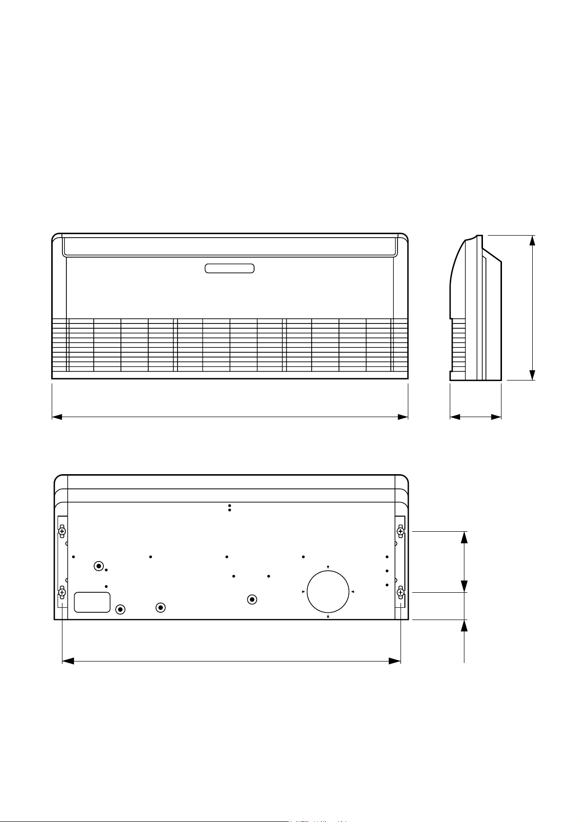
DIMENSIONS
INDOOR UNIT
(Unit : mm)
700
1,660 240
1,600
2007.10.29 2
130 300
Page 4
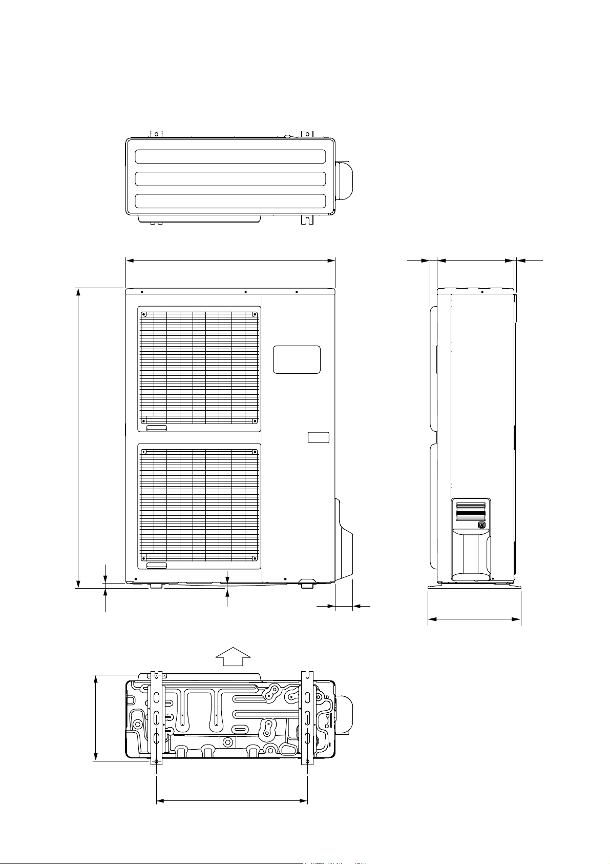
OUTDOOR UNIT
(Unit : mm)
31900 330 12
1,290
21
9
77
400
Air Flow
370
650
2007.10.29 3
Page 5
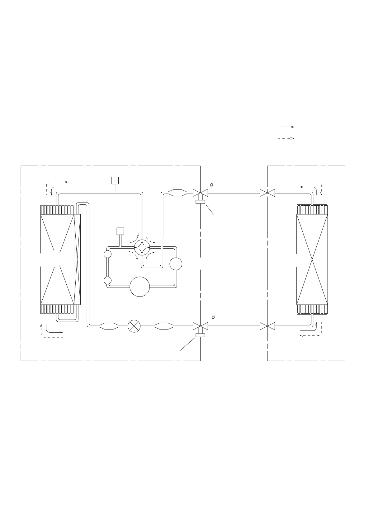
REFRIGERANT SYSTEM DIAGRAM
Refrigerant direction
: Cool
: Heat
OUTDOOR UNIT INDOOR UNIT
Condenser
High
Pressure
Switch
Muffler x 2
Strainer
Pressure
Check Valve
4-way
Valve
Compressor
Expansion
Valve
Strainer
Accumulator
Strainer
Charging Valve
Refrigerant Pipe
15.88mm (5/8")
Charging
Valve
Evaporator
Refrigerant Pipe
9.52mm (3/8")
2006.10.29 4
Page 6
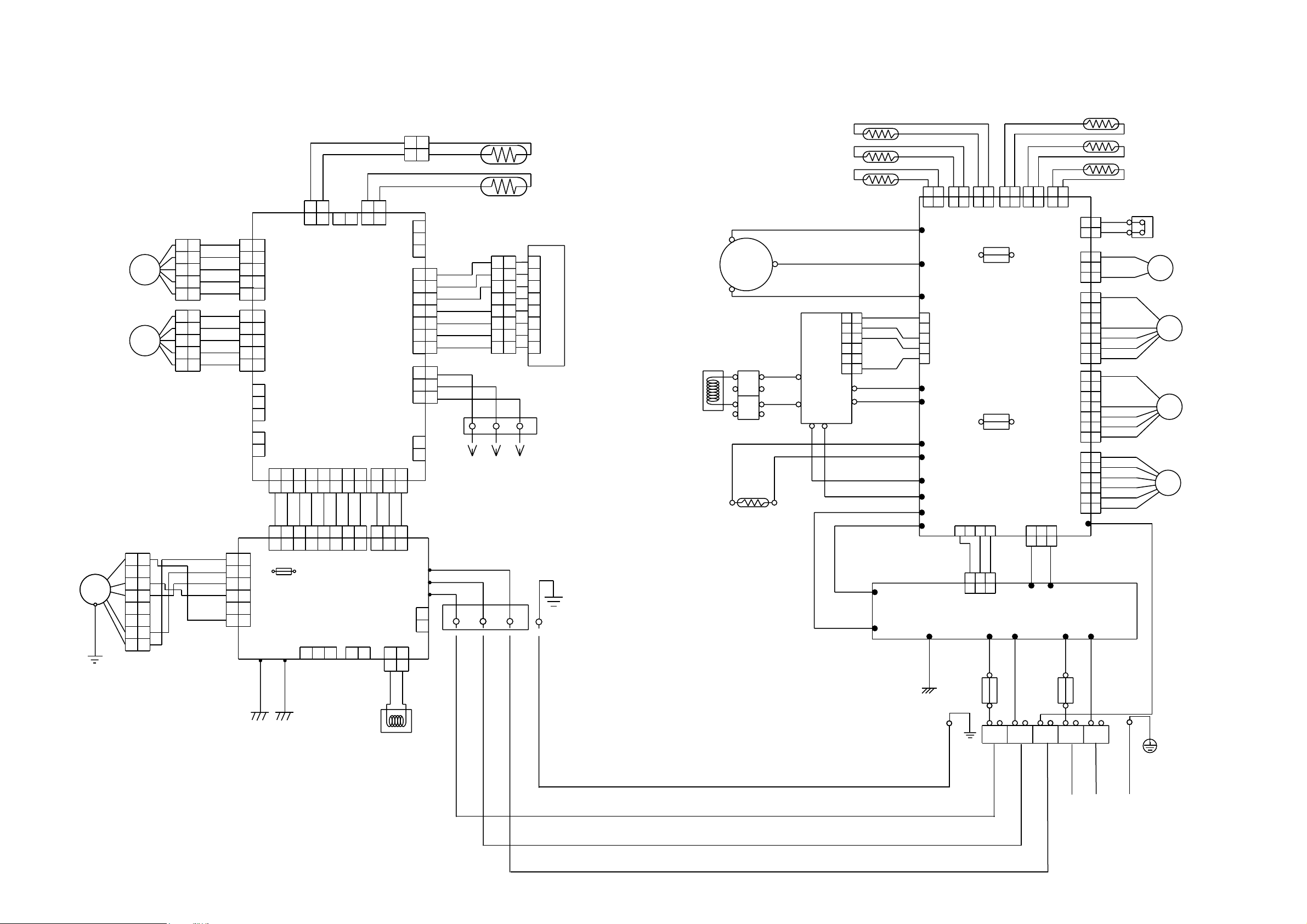
CIRCUIT DIAGRAM
INDOOR UNIT OUTDOOR UNIT
STEP MOTOR
( RIGHT / LEFT )
STEP MOTOR
( UP / DOWN )
DC FAN MOTOR
F M
GREEN
/ YELLOW
OUTDOOR TH.
COMPRESSOR TH.
HEAT SINK TH.
HIGH PRESSURE SWITCH
RED
RED
BLACK
BLACK
RED
SOLENOID COIL
4WV
FAN MOTOR 1
BLACK
WHITE
YELLOW
BROWN
RED
F M
FAN MOTOR 2
BLACK
WHITE
YELLOW
BROWN
RED
BROWN
BLUE
ORANGE
YELLOW
WHITE
F M
EXPANSION
VALVE COIL
E V
WHITE
BLACK
YELLOW
ORANGE
ORANGE
BLACK
TM102
TM101
BLACK
BROWN
BLACK
RED
BLUE
RED
2
1
1
CN24
2
1
1
CN21
2
121
1
CN22
2
2
1
2
1
2
CN23
121
CN26
U
W305
V
W304
FUSE
F4 T 5A - 250V
W
W303
1
2
CN407
3
4
CONTROLLER PCB ASSY
5
( MAIN PCB )
W12
W13
W21
W22
W16
W17
W10
W11
FUSE
F2 T 3.15A - 250V
CN1
2
1
4
3
RED
BROWN
BLACK
2
1
3
1 2
3
CN1
1
1
W9
POWER SUPPLY PCB ASSY
W3
GREEN
W6
W7
WHITE
BLACK
PIPE TH.
PIPE MID. TH.
S ( S )
ACTPM
WHITE
L1
L2
-
+
1
1
2
2
3
3
4
4
5
5
6
6
P
N
WHITE
BLACK
BROWN
RED
ORANGE
YELLOW
CN106
1
22
1
2
3
1
2
3
4
5
6
7
1
2
3
1
2
1
2
GRAY
GRAY
BLACK
BLACK
BROWN
1
RED
2
ORANGE
3
WHITE
4
BLUE
5
PURPLE
6
GRAY
7
RED
1
WHITE
2
BLACK
3
RED
WHITE
BLACK
PIPE TH.
ROOM TH.
INDICATOR PCB ASSY
1
2
3
4
5
6
7
8
1
1
2
2
3
3
4
4
5
5
6
6
7
7
8
8
TERMINAL
1
3
2
TO REMOTE CONTROL UNIT
( OPTION )
TERMINAL
1 2 3
DISCHARGE TH.
COMPRESSOR
R ( R )
C M
C ( T )
TERMINAL
BROWN
CHOKE
COIL
POSISTOR
M
M
1
2
3
4
5
1
2
3
4
5
BROWN
1
RED
2
ORANGE
3
YELLOW
4
WHITE
5
BROWN
1
RED
2
ORANGE
3
YELLOW
4
WHITE
5
BLACK
BLACK
1
2
1 2
CN5
1
1
2
2
3
3
CN12
4
4
5
5
1
1
2
2
3
3
4
4
5
5
CONTROLLER
PCB ASSY
CN11CN9
( MAIN PCB )
1
1 2
1
2
CN7 CN8
1
2
1
2
CN13
CN14
3
1
2
CN10
1 2
1 2
GRAY
1
1 2
1
1
2
2
3
3
4
4
5
5
6
6
7
7
8
8
BROWN
YELLOW
WHITE
BLACK
RED
1
1
2
2
3
3
4
4
5
5
6
6
F101
FUSE
3.15A
CN105
250V
E101 E102
CN4 CN1
34567
34567
GRAY
2
GRAY
GRAY
GRAY
GRAY
3 4 567
34567
CN104
POWER SUPPLY
PCB ASSY
CN102
1
2
3
8
8
GRAY
GRAY
8
8
CN103
1 2
1 2
1
1 2
1
CN101
2
GRAY
GRAY
2
CN108
1
CN6 CN3
3
3
GRAY
3
3
W105
W102
W101
2
1 2
2
CN34
2
2
WHITE
BROWN
1
CN25
CN800
CN801
3
3
BLACK
W8
BLUE
BLACK
2
2
CN37
CN30
CN27
W200
W1
BLACK
1
2
1
2
3
1
2
3
4
5
6
7 7
1
2
3
4
5
6
7
1
2
3
4
5
6
W2
1
2
1
2
3
1
2
3
4
5
6
1
2
3
4
5
6
7
1
2
3
4
5
6
WHITE
GREEN
GREEN
WHITE
WHITE
COIL
2007.10.29 5
EARTH
FUSE
10A
FUSE
25A
RED
1
2
3
N
L
EARTH
POWER SOURCE
Page 7
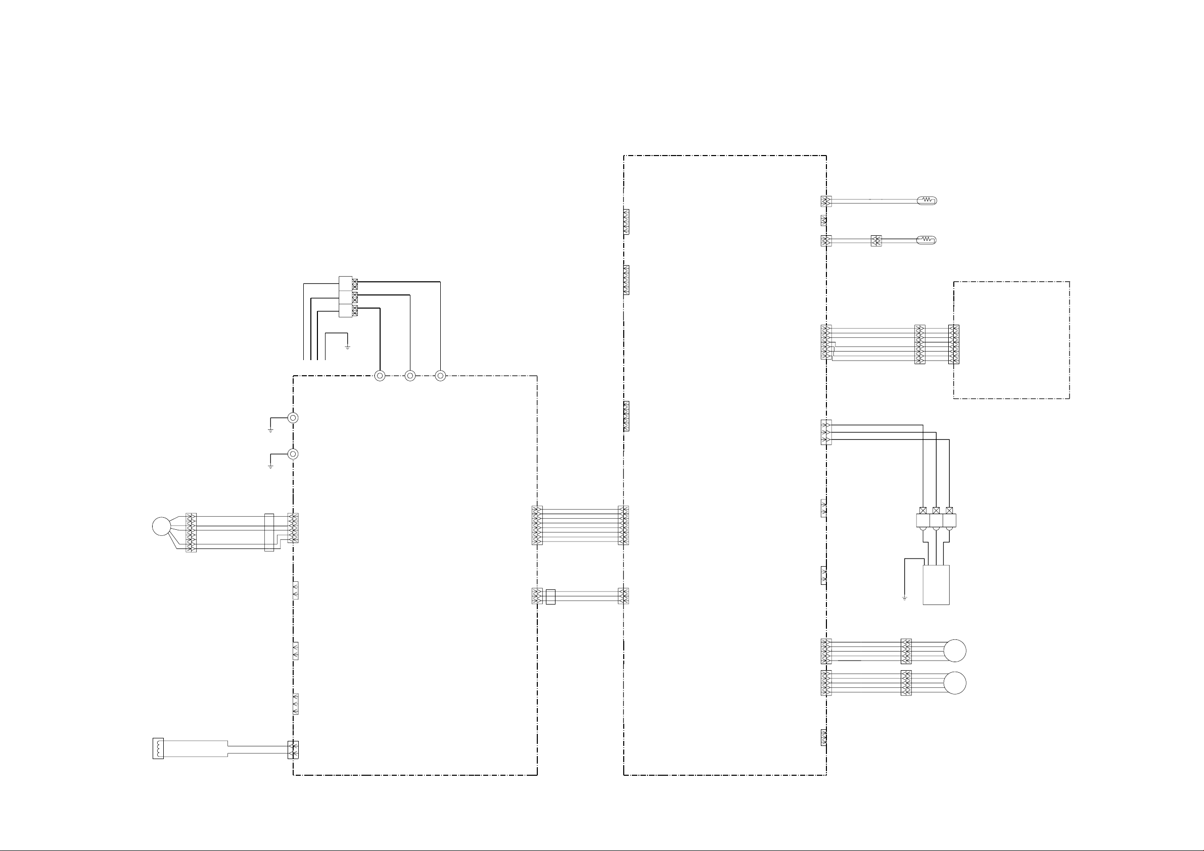
INDOOR PCB CIRCUIT DIAGRAM
CONTROL UNIT
ABHA36LAT : EZ-0061EHSE
ABHA45LAT : EZ-0061DHSE
CN2-1
CN2-2
CN2-3
CN2-4
CN2-5
CN2
B5P-SHF-1AA
WHITE
CN8
B02B-XASK-1-A
WHITE
CN7
B02B-XAYK-1-A
YELLOW
CN5
B02B-XAKK-1-A
BLACK
CN8-1
CN8-2
CN7-1
CN7-2
CN5-1
CN5-2
BLACK
BLACK
BLACK
BLACK
GRAY
GRAY
ROOM TH.
PIPE TH. ( M I D )
DC FAN MOTOR
F M
1
UL1015 AWG22 RED
2
3
UL1015 AWG22 BLACK
UL1015 AWG22 WHITE
4
5
6
UL1015 AWG22 YELLOW
7
UL1015 AWG22 BROWN
8
DRAIN PUMP
E I B OUT
UL1015 AWG16
GREEN
UL1015 AWG16
GREEN
EMI FILTER
ATFC-25-15-12
2 TURN
E I B I N
TERMINAL BOARD
OUTDOOR UNIT
E101
E102
CN105-6
CN105-5
CN105-4
CN105-3
CN105-2
CN105-1
CN106-1
CN106-2
CN103-1
CN103-2
CN102-1
CN102-2
CN102-3
3
2(N)
1
UL1015 AWG20 BLACK
UL1015 AWG20 WHITE
W101
W102
POWER SUPPLY PCB ASSEMBLY
K06AL-0606HSE-P0
CN105
B5P6-VH-B
WHITE
CN106
B2P3-VH-B-E
BLUE
CN103
B2B-XH-AM
WHITE
CN102
B3B-XH-AM
WHITE
UL1015 AWG20 RED
W105
CN104
B08B-PASK-1
WHITE
CN101
B03B-PASK-1
WHITE
CN104-1
CN104-2
CN104-3
CN104-4
CN104-5
CN104-6
CN104-7
CN104-8
CN101-1
CN101-2
CN101-3
POWER DRIVE
UL1430 AWG26 GRAY
UL1430 AWG26 GRAY
UL1430 AWG26 GRAY
UL1430 AWG26 GRAY
UL1430 AWG26 GRAY
UL1430 AWG26 GRAY
UL1430 AWG26 GRAY
UL1430 AWG26 GRAY
DC SUPPLY
UL1430 AWG26 GRAY
UL1430 AWG26 GRAY
UL1430 AWG26 GRAY
EMI FILTER
ZCAT1518-0730
2 TURN
CN15-1
CN15-2
CN15
CN15-3
CN15-4
B06B-XASK-1-A
WHITE
CN15-5
CN15-6
CONTROLLER PCB ASSEMBLY ( MAIN PCB )
ABHA36LAT : K06AK-0607HSE-C1
ABHA45LAT : K06AK-0606HSE-C1
CN13
B07B-PASK-1
WHITE
CN3-1
CN3-2
CN3
CN3-3
CN3-4
B06B-PASK-1
WHITE
CN3-5
CN3-6
CN4-1
CN4-2
CN4-3
CN4-4
CN4-5
CN4-6
CN4-7
CN4-8
CN1-1
CN1-2
CN1-3
CN4
B08B-PASK-1
WHITE
CN1
B03B-PASK-1
WHITE
CN14
B03B-XAKK-1-A
BLACK
CN6
B02B-PAMK-1
GREEN
CN10
B02B-PAOK-1
ORANGE
CN11
B05B-XASK-1-A
WHITE
CN12
B05B-XARK-1-A
RED
CN13-1
CN13-2
CN13-3
CN13-4
CN13-5
CN13-6
CN13-7
CN14-1
CN14-2
CN14-3
CN6-1
CN6-2
CN10-1
CN10-2
CN11-1
CN11-2
CN11-3
CN11-4
CN11-5
CN12-1
CN12-2
CN12-3
CN12-4
CN12-5
UL1430 AWG28 BROWN
UL1430 AWG28 RED
UL1430 AWG28 ORANGE
UL1430 AWG28 WHITE
UL1430 AWG28 BLUE
UL1430 AWG28 PURPLE
UL1430 AWG28 GRAY
FRESH AIR
UL1430 AWG28 BROWN
UL1430 AWG28 RED
UL1430 AWG28 ORANGE
UL1430 AWG28 YELLOW
UL1430 AWG28 WHITE
UL1430 AWG28 BROWN
UL1430 AWG28 RED
UL1430 AWG28 ORANGE
UL1430 AWG28 YELLOW
UL1430 AWG28 WHITE
1
1
BROWN
RED
2
2
3
3
ORANGE
4
4
YELLOW
WHITE
5
5
BLUE
6
6
PURPLE
7
7
8
8
GRAY
UL1430 AWG22 RED
UL1430 AWG22 WHITE
1
2
EARTH WIRE
REMOTE CONTROL UNIT
( OPTION PARTS )
BROWN
RED
ORANGE
YELLOW
WHITE
BROWN
RED
ORANGE
YELLOW
WHITE
INDICATOR PCB ASSEMBLY
K04GN-0402HSE-D0
CN201-1
CN201-2
CN201-3
CN201-4
CN201-5
CN201-6
CN201-7
CN201-8
CN201
JC25-08HG
WHITE
UL1430 AWG22 BLACK
TERMINAL BOARD
3
LOUVER
M
U - D
LOUVER
M
L - R
CN108
CN108-1
CN108-2
B2P3-VH-B
WHITE
NORMAL COIL
RELY41-22
22mH
2.2A
UL1015 AWG20 WHITE
UL1015 AWG20 WHITE
2007.10.29 6
B03B-XARK-1-A
CN9
CN9-1
CN9-2
CN9-3
RED
FLOAT SWITCH
Page 8
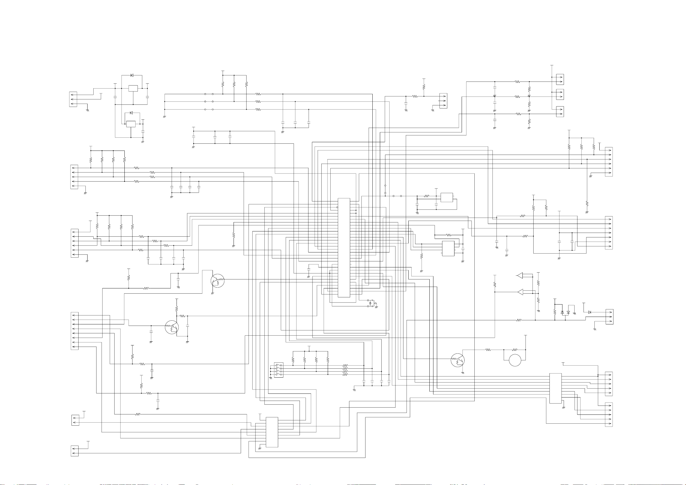
INDOOR UNIT
CONTROLLER PCB ASSEMBLY ( MAIN PCB )
ABHA36LAT : K06AK-0607HSE-C1
ABHA45LAT : K06AK-0606HSE-C1
CN1
B03B-PASK-1
DC SUPLLY
CN2
B5P-SHF-1AA
TEST
CN3
B06B-PASK-1
SP PCB
CN4
B08B-PASK-1
POWER DRIVE
CN6
B02B-PAMK-1
FRESH AIR
CN10
B02B-PAOK-1
HEATER
1
2
3
1
2
3
4
5
1
2
3
4
5
6
1
2
3
4
5
6
7
8
13.5V
1
2
1
2
5V
13.5V
13.5V
13.5V
5V
C1
10/
50V
R15 - R18
10K <1/10W> x 4
5V
10K <1/10W> x 3
R24
R23
+
R26
10K
<1/10W>
<1/10W>
1SS355
NJM7812
1
D1
1SS355
I C2
NJM7805
1
I
R32
R67 1.0K
<1/10W>
5V
R30
10K
<1/10W>
D4
I C8
I
G
5V
12V
3
O
G
2
+
5V
3
O
C3
2
0.01
<F>
R19
R22
1.0K <1/10W> x 4
R66
C35 C12
R25
1.0K
<1/10W>
R31
10K
<1/10W>
5V
R34
R33
1.0K
10K
<1/10W>
R27
330
<1/10W>
C2
10/
50V
R20
R21
1.0K <1/10W> X 3R63
R64
1000P <R> x 3
<1/10W>
1
C15
0.01
<F>
C17
0.01
<F>
C18
0.01
<B>
CUSTOM CODE
CUSTOM CODE
HEATING FAN DELAY
R65
C37
C14
1000P
<R>
0.1
<F>
C11
5V
R29
R28
390
10K
<1/10W>
3
2
Q1
DTC124EKA
C16
0.01
<F>
5V
C32
+
100/
6.3V
C4 - C7
0.01 <F> x 4
JM1
JM2
JM3
C33
0.1
<F>
<1/10W>
Q3
DTC124EKA
3
2
5V
R1 - R3
10K <1/10W> x 3
C28
0.1
<F>
R70
10K
1
R4 - R6
1.0K <1/10W> x 3
8
7
6
5
SW1
CFS-0402MC
I C3
13.5V
uLN2003
9
SK
I 1
16
O1
I 2
O2
15
I 3
14
O3
I 4
13
I 5
O4
12
O5
I 6
I 7
11
O6
10
O7
8
GND
1
2
3
4
5
6
7
C8 - C10
0.1 <F> x 3
4
3
2
1
C36
0.47
<F>
5V
I C1
uPD78F0535
34
AVREF
39
I C
RST
36
43
P00
44
P01
P02
45
46
P03
33
P10
32
P11
31
P12
30
P13
29
P14
28
P15
27
P16
26
P17
18
P20
19
P21
20
P22
21
P23
22
P24
P25
23
P30
11
12
P31
13
P32
14
P33
38
XT1
37
XT2
41
X1
X2
40
AGND
25
9
GND0
42
GND1
R11 - R14
10K <1/10W> x 4
R7 - R10
1.0K <1/10W> x 4
AVDD
VDD0
VDD1
35
10
24
15
P34
16
P35
P36
17
57
P40
58
P41
59
P42
P43
60
P44
61
62
P45
63
P46
64
P47
P50
1
2
P51
3
P52
4
P53
5
P54
6
P55
P56
7
8
P57
53
P64
54
P65
55
P66
56
P67
47
P70
48
P71
49
P72
P73
50
51
P74
52
P75
2007.07.29 7
3
2
1
X1
5.00MHz
<CSTLS>
C19 - C22
0.1 <F> x 4
JM5
0R0
JM6
0R0
C31
0.01
<F>
R45
10K
<1/10W>
R46
1.0K
<1/10W>
C27
0.1
<F>
5V
R56
100K
<1/10W>
0.1 <F>
R37
10K
<1/10W>
C38
1
2
3
5V
FLOAT SWITCH
CN9
B03B-XARK-1-A
I C7
S80842
2
3
NC
VDD
1
4
OUT GND
R40
10K
<1/10W>
1
CS
VCC
2
SK
DO
3
D I
NC
6
GND
NC
I C5
BR93L56RF
DTC124EKA
1
5V
ROOM TH.
1
CN8
2
C25
50V
12V
R48
10K
1
2
3
4
5
6
7
10/
I C4
1
2
1
2
5V
+
DAN217U
13.5V
SK
O1
O2
O3
O4
O5
O6
O7
GND
B02B-XASK-1-A
PIPE TH. ( ENT )
CN7
B02B-XAYK-1-A
PIPE TH. ( MID )
CN5
B02B-XAKK-1-A
5V
R49 - R51
10K <1/10W> x 3
C26
0.01
<F>
D2
1 2
3
9
16
15
14
13
12
11
10
8
12V
R52
10K
<1/10W>
D3
D1FS4A
FLASH
CN15
5V
B06B-XASK-1-A
1
2
3
4
5
6
INDICATOR
CN13
B07B-PASK-1
1
2
3
4
5
6
7
CN14
B03B-XAKK-1-A
REMOTE CONTROL UNIT
1
2
3
CN11
B05B-XASK-1-A
LOUVER ( UP / DOWN )
1
2
3
4
5
1
2
3
4
5
CN12
B05B-XARK-1-A
LOUVER ( RHIGT / LEFT )
C29
0.1
<F>
C30
0.1
<F>
C34
0.1
<F>
NC
R57
1.0K
<1/10W>
R58
1.0K
<1/10W>
R62
1.0K
<1/10W>
R41 1.0K
<1/10W>
R43
10K
<1/10W>
R59
10K
<1/10W>
R60
49.9K
<1/10W>
R61
49.9K
<1/10W>
5V
R44
10K
<1/10W>
5V
C23
8
C13
4
0.1
7
5
<F>
0.01
<F>
5V
R55
10K
<1/10W>
R36
Q2
3
0R0
C24
1000P
<R>
7
BA10393F
1
BA10393F
R47
390
<1/10W>
R35
1.0K
<1/10W>
R42
47
<1/10W>
6
-
5
+
I C6-2
2
-
3
+
I C6-1
13.5V
12V
R54
15.4K
<1/10W>
R53
28K
<1/10W>
<1/10W>
B Z
2
BZ1
PKM13EPYH-4000-A0
uLN2003
1
I
2
I
I
3
4
I
5
I
I
6
I
7
Page 9
INDOOR UNIT
POWER SUPPLY PCB ASSEMBLY
K06AL-0606HSE-P0
L
I C26-14
F101
3.15A - 250V
<BET>
FH102
VA101
470V
<TNR>
PFC5000-0702F
x 2
SA101
RA-362M
VA102
470V
<TNR>
C101
0.22
<LE>
W101
BLACK
W102
WHITE
FH101
LF101
ELF20N018A
1
2
4
3
C104
0.22
<LE>
C105
0.01
<YE>
C106
0.01
<YE>
NORMAL COIL
2
1
CN108
B2P3-VH-B
E102
GREEN
<RS-2W>
C108
4700
D102
1SR139-600
15V
+
R110
10K
<1/10W>
R103
62K
ZFT22B03
2
3
5
6
7
8
D106
D1FL20U
C110 0.047 <ECQB>
D103
D1FL20U
D104
MTZJ5.1B
<1/4W>
R109
330
D1FL20U
+
T101
D105
C111
100/
25V
D108
D2FL20U
12
10
1000/
A
C113
25V
C114
0.01
<KH>
C115
0.01
<KH>
R108
100
<1/2W>
13.5V
R111
+
10K
<1/10W>
340V
<ECQM>
R104
330K
<2W>
C109
220P/
2.0kV
R105
1.5
75
Q101
2SC5354
2
3
2SC1815
R107
100
<1/10W>
1
Q102
1
2
3
D107
RD16M
<B1>
C112
330/
25V
D101
1
D3SB60
3
2
4
C107
+
270/
450V
<ECKE>
<RS-2W>
R106
<RS-2W>
C118
0.01
<KH>
POWER DRIVE
B08B-PASK-1
SERIAL I N
SERIAL I NT
SERIAL ON
DRAIN PUMP
DC FAN-OUT
DC FAN-FEEDBACK
EX. SIGNAL-OUT
EX. SIGNAL-I N
DC SUPPLY
I C26-10
CN104
CN101
B03B-PASK-1
E101
N
GREEN
CN105
B5P6-VH-B
6
5
4
3
2
1
G5NB-1A
4
2
I C101
TLP621
<GB>
4
3
<AG601>
DC FAN MOTOR
K101
1
3
L102
BLm18
5V
<AG601>
1
2
L103
BLm18
13.5V
R112
330
<1/10W>
C116
0.01
<B>
CN102
B3B-XH-AM
3
2
1
2
1
E I B I N
W105
CN103
B2B-XH-AM
8
RED
SERIAL
E I B OUT
VA103
470V
<TNR>
IC26-14
7
L
IC26-14
L
IC26-10
N
IC26-10
I C 105
H I 2002R
101418
6
N
K102
G5NB-1A
342
1
13.5V
5 4 3 2
3 2 1
5 4
RC101
120/
0.2
1
5V
CN106
B2P3-VH-B-E
2
1
DRAIN PUMP
C119
0.01
<KH>
I C103
TLP621
<GB>
4
3 2
340V
15V
1
A
R114
4.7K
<1/10W>
R115
6.8K
<1/4W>
R113
330
<1/10W>
15V
5V
1
2
3
4
5
6
7
8
1
2
3
1
2
TLP621
I C104
<GB>
15V
4
3
R116
1.0K
<1/4W>
R117
<1/4W>
5V
C121
0.1
<F>
820
+
C117
100/
25V
AA
13.5V
C120
0.1
<F>
2007.07.29 8
Page 10

TO CONTROLLER PCB ASSEMBLY
( OPERATE )
( TIMER )
( LOUVER )
( LOUVER )
( 5V )
( REMOTE CONTROL )
( GND )
( MANUAL AUTO SWITCH )
INDOOR UNIT
INDICATOR PCB ASSEMBLY
K04GN-0402HSE-D0
R201
330 <1/4W>
R202
330 <1/4W>
BROWN
RED
ORANGE
YELLOW
WHITE
BLUE
PURPLE
GRAY
CN201
08/08 JC/XMR
1430 L=300
1
2
3
4
5
6
7
8
R203
330 <1/4W>
SW201
EVQPAG04K
1
2
5V
D205 EBR3864X <RED>
D206 EMPG3863X <GREEN>
D207 EMAA3863X <ORANGE>
C202
C201
+
10/
3
4
16V
0.1
<F>
JM201
PHA201
P I C-37143TH5
2
VCC
OUT
1
GND
3
2007.07.29 9
Page 11

POWER SOURCE
230V
50Hz
INDOOR UNIT
N
L
3
2
(N)
1
5P TERMINAL
HP-T3061-3
UL1015
TLC 25A - 250V, B
AWG12
( 250V 25A )
WHITE
UL1015
AWG12
BLACK
UL1015
AWG20
RED
UL1015
AWG20
WHITE
UL1015
AWG20
BLACK
F202
FSL 250 10 ( EM )
( 250V 10A )
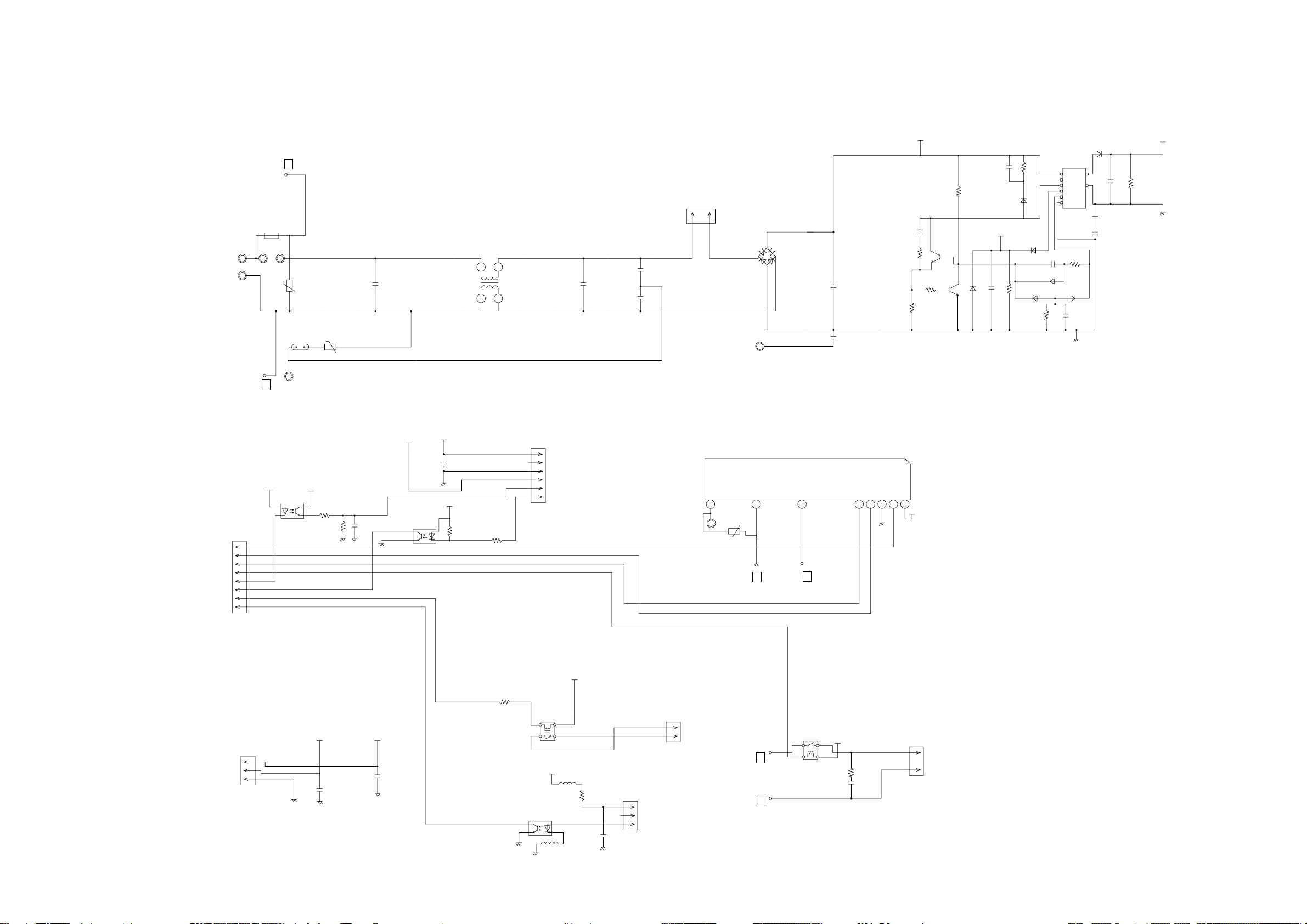
OUTDOOR PCB CIRCUIT DIAGRAM
INVERTER ASSEMBLY
AOHA36LATL : EZ-00603HUE
AOHA45LATL : EZ-00604HUE
F201
EMI FILTER 1
TFC-25-15-12A
UL1015
AWG12
BLACK
UL1015
AWG20
BLACK
1T
UL1015
AWG16
GREEN
EARTH
W1
B
W6
B
POWER SUPPLY PCB ASSY
W2
B
W7
B
W3
B
K04BA-0401HUE-P0
B3B-XASK-1-A
03 VH / SIN
1015 L=250
CN1
WHITE
CT OUT
TM101
TM102
W9
W8
B
B
1
2
3
UL1015 AWG14 BLACK
UL1015 AWG14 WHITE
UL1015 AWG20 WHITE
UL1015 AWG20 BLACK
UL1007 AWG24 BLACK
UL1007 AWG24 BROWN
UL1007 AWG24 RED
W10
B
W11
B
CN34
1
B2P3-VH-B-Y
YELLOW
3
CN1
03 XA / 172520
1
1007 L=180
WHITE
3
4
AC VOLT I N
CT
W16
W17
W21
W22
CHOKE COIL
L=0.3MH
30A
UL1015
AWG14
EMI FILTER 2
TFC-25-15-12A
2T
BROWN
+
UL1015
AWG14
RED
B
UL1015
AWG14
BLACK
B
UL1015
AWG20
ORANGE
B
UL1015
AWG20
ORANGE
B
ZPR0YCE400A300
-
UL1015
AWG14
BROWN
L1 L2
ACTPM
SACT32010F1
P
N1
1
2
3
4
5
6
EMI FILTER 3
TFC-25-15-12A
2T
UL1015 AWG14 YELLOW
UL1015 AWG14 BLUE
UL1007 AWG24 BROWN
UL1007 AWG24 RED
UL1007 AWG24 ORANGE
UL1007 AWG24 YELLOW
W12
B
W13
B
CN407
06 PH / 172520
1
1007 L=480
WHITE
3
4
5
ACTPM CONTROL
W305
W304
W303
B
B
B
UL1015 AWG14 RED
UL1015 AWG14 WHITE
UL1015 AWG14 BLACK
C M
COMPRESSOR
DC FAN MOTOR 1
DC FAN MOTOR 2
EXPANSION VALVE
4-WAY VALVE
PRESSURE SWITCH
COMPRESSOR TH.
HEAT SINK TH.
DISCHARGE TH.
PIPE TH.
OUTDOOR TH.
PIPE ( MID ) TH.
F M
F M
M
BLACK
BLACK
BROWN
BROWN
BLACK
BLACK
BROWN
BROWN
BLACK
BLACK
BLUE
BLUE
BLACK
BLACK
RED
BLACK
WHITE
YELLOW
BROWN
RED
BLACK
WHITE
YELLOW
BROWN
RED
BROWN
BLUE
ORANGE
YELLOW
WHITE
RED
RED
W200
B
1
2
CN800
3
4
B07B-XASK-1-A
5
WHITE
6
7
1
2
3
CN801
4
B07B-XAKK-1-A
5
BLACK
6
7
1
2
CN27
3
4
B06B-XARK-1-A
5
RED
6
1
CN30
179844-1
3
WHITE
1
CN37
2
B02B-XARK-1-A
RED
CN26
B02B-XAMK-1-A
1
GREEN
2
CN25
B02B-XAKK-1-A
1
BLACK
2
CN21
1
B02B-XH-AM-Y
2
YELLOW
1
CN22
2
B2B-XH-AM-R
RED
1
2
CN23
B02B-XAEK-1-A
BLUE
1
2
CN24
B2B-XH-AM
WHITE
SERIAL
CONTROLLER PCB ASSY ( MAIN PCB )
AOHA36LATL : K06DZ-0601HUE-C1
AOHA45LATL : K06DZ-0600HUE-C1
CN601
B10B-PASK-1
MAIN FLASH
WHITE
1
5V
2
GND
3
TAUX
4
TTXD
5
TRXD
TMODE
6
TAUX3
7
TCK
8
/ TRES
9
/ TICS
10
2007.07.29 10
Page 12

AC VOLT I N
B2P3-VH-B-Y
SERIAL
4-WAY VALVE
PRESSURE SWITCH
B02B-XARK-1-A
COMPRESSOR TH.
B02B-XAMK-1-A
HEAT SINK TH.
B02B-XAKK-1-A
DISCHARGE TH.
PIPE TH.
OUTDOOR TH.
B02B-XAEK-1-A
W22
ORANGE
W21
ORANGE
W10
BLACK
W11
WHITE
CN34
YELLOW
W200
CN30
179844-1
WHITE
CN37
CN26
GREEN
CN25
BLACK
CN21
B2B-XH-AM
YELLOW
CN22
B2B-XH-AM
CN23
CONTROLLER PCB ASSEMBLY ( MAIN PCB )
AOHA36LATL : K06DZ-0601HUE-C1
AOHA45LATL : K06DZ-0600HUE-C1
R51 27K
5V
<1/10W>
R55
R56 27K
1.0K
R50 10K
<1/10W>
<1/10W>
R52
1.0K
C51
0.022
<F>
<1/10W>
1
3
Q51
2SC2412K
2
<BQ>
<1/10W>
JM156
x 2
C53
<F>
C180
0.022
P-S I
P-S I1
P-POWER
P-AFE
P-AFDC
P-CP-POS
C95
100P
<CH>
<1/10W>
<1/10W>
VOLTAGE LOCK OUT
C35, C26
0.01 <F>
R113
1.0K
R114
27K
VA103
470V
<TNR>
MAIN CURRENT
2
+
3
-
D101
D25XB60
18
14 10 5 432 1
1
4
7
HY I C1
HU2001
C115
0.1
<HCP>
6
B
W16
RED
B
W17
BLACK
5V
2
543
18
B
B
4
12V
B
B
PFC5000
-0702
FH2
3
1
3
1
2
K101 DW12D1
PFC5000
F4
-0702
T 5A
FH1
250V
SERIAL
RED
B
2SC2412K <BQ>
100K <2W>
12V
D28
SLR-332VR
<RED>
12V
R43 2.2K
<1/4W>
1C
2C
15
3C
14
4C
13
5C
12
6C
11
7C
10
COM
9
I C3
uLN2003A
1B
116
2B
2
3
3B
4B
4
5B
5
6
6B
7B
7
8
E
JM157
P-FM1SEL
P-V2
P-4WV-AC
P-LED
P-PR
P-SO1
P-SO
1
2
CR5
RE1202
K17 G5NB-1A
3
12V
124
4WV
D153, D152,
D151, D150
SLR-332VR
<RED> x 4
5V
2.2K
1
2
R91
1
2
1
2
1
2
1
2
1
2
R90
L202
BL02Rn1
5V
BL02Rn1
RED
RED
<1/10W>
x 2
C71
L201
4.75K 1%
4.75K 1%
38.3K 1%
1.0K <1/10W> x 2
R93
R92
0.1
C70
0.01 <F> x 2
R100
13K
<1/10W>
R98
<1/10W>
R63
13K
<1/10W>
R65
<1/10W>
R67
<1/10W>
<F>
x 2
<1/10W>
<1/10W>
<1/10W>
<1/10W>
<1/10W>
C73
R101
10K
R99
10K
R62
10K
R64
10K
R66
10K
C72
PR-SW
C60
1.0
<F>
C61
1.0
<F>
C37
1.0
<F>
C38
1.0
<F>
C39
1.0
<F>
5V
C91
0.1
<F>
8 VCC
4
7
5
<1/10W>
THERMISTOR
I C201
BR93L56RF-WE2
1
CS
2
DO
SK
3
NC
D I
6
GND
NC
R206
10K
EEPROM
P-E2PCS1
P-E3PSK1
P-E2PD I 1
C56
1.0K
<1/10W>
P-SWPRS1
P-SWPRS2
P-CMPTH
P-AN-HT
P-AN-TD
P-AN-TT
P-AN-TA
6
5
4
SW1
DSS803
AOHA36LATL
CN24
B2B-XH-AM
PIPE ( MID ) TH.
1
2
<1/10W>
3
2
<1/10W>
1
<1/10W>
R35
10K
<1/10W>
R68 4.75K
<1/10W>
1%
R16
2.2K
R17
1.8K
R18
1.0K
5V
R11, R195
P-V2
<1/10W>
R34
1.0K
10K <1/10W> x 2
C40 0.1
<F>
C77
0.1
<F>
P-AN-TT2
P-AN-HT
P-CMPTH
P-AN-TT
P-AN-TA
P-AN-TD
FM2FDB
SUB-CLK
P-FM2POW
P-POWER
P-AN-CT
P-FM1POW
TTXD-1
TAUX3-1
P-AFS
P-CP-POS
5V
P-S I
P-SO
P-PR
P-LED
P-4WV-AC
P-TRIP
P-EPV-A
P-EPV-B
P-EPV-C
P-EPV-D
1
MB90462
17
16
2
35
3
59
58
60
21
34
47
27
28
29
30
31
32
33
57
41
42
43
44
10
9
8
7
5
6
4
22
23
3
2
I C1
P63
P62
P46
P12
P50
P37
P36
P40
MD2
P11
P26
P02
P03
P04
P05
P06
P07
P10
C
P20
P21
P22
P23
P57
P56
P55
P54
P52
P53
P51
X0
X1
X1
8.00MHz
<EFO>
MICOM-MAIN
P-AN-TT2
C78
0.1
<F>
AVCC
RSTX
AGND
VCC
P00
P01
P17
P13
P14
P15
P16
AVR
P24
P25
P30
P31
P32
P33
P34
P35
P60
P61
MD0
MD1
P44
P43
P42
P41
P45
P27
GND
GND
C79
<F>
56
11
25
26
40
36
37
38
39
12
45
46
50
51
52
53
54
55
14
15
18
20
64
63
62
61
1
19
48
13
24
49
0.1
0.1 <F> x 2
R608 10K <1/10W>
U
X
V
Y
W
Z
R36
1.0K
<1/10W>
C19
R72 1.0K
<1/10W>
C17
0.01
<F>
5V
C18
C16
4.7/
50V
<PS>
5V
R158
10K
<1/10W>
SW2
KSM0632B
+
<PS>
C20
4.7/
50V
5V
+
2
1
Q1
2SC5354
R140 1.2
TAUX-1
P-E2PCS1
P-FM1SEL
FM1FDB
P-E2PD I1
P-E2PSK1
P-AFDC
P-AFE
P-U
P-X
P-V
P-Y
P-W
P-Z
R126 - R128
10K <1/10W> x 3
SUB-FWD
SUB-BKWD
TMODE-1
P-SWPRS2
P-SWPRS1
TCK-1
TRXD-1
R73 82K
<1/10W>
5
SUB
VCC
4
VOUT
3
GND
NC
I C6
BD4742G
<1/2W>
R407, R403
10K <1/10W>
x 2
5V
R102
3
<1/10W>
1
2
R103
4.7K
<1/10W>
Q91
x 2
R6
R1
2
1
3
D1
D1FL20U
5V
W12
YELLOW
W13
BLUE
x 2
15V
22K
4.7/50V <PS>
R3 100
<1W>
D10
RD5.6ES
R4 330
<1/4W>
P-AFS
RSTX-1
I C400-1
5V
uPC393
I C400-2
uPC393
I C11-1
uPC393
1
R115 1M
<1/10W>
R2 1.0K
<RS-3W>
C2 0.047
D1FL20U
<B2>
100/16V
R411
<1/10W>
C416
1000P
TAUX-1
TTXD-1
TRXD-1
TMODE-1
TAUX3-1
TCK-1
RSTX-1
B
B
-
+
220P
<BN>
<ECQB>
<PJ>
22K
<B>
DTC124EUA
R201
220K
<2W>
660/450WV x 3
1
7
15V
2
3
C90
+
+
C201
C202
C203
SMOOTHING CIRCUIT
15V
R408
C409
6.65K
10/
<1/10W>
25V
1%
<PS>
15V
+
2
-
3
+
6
-
5
+
C412
+
0.1
<F>
C88
0.1
<F>
1.0K <1/10W>
C411
C414
0.01
0.01
<F>
<F>
2
C89
470P
<B>
DAN217U x 2
C87
330P
COMP POSITION DETECT
<B>
SW POWER SUPPLY
T1
JPZ-200
16
C1
15
13
12
10
9
D1
D100
C3
D1FL20U
+
220/
35V
P-U
P-V
P-W
P-X
P-Y
P-Z
P-TRIP
P-FM1POW
FM1FDB
P-FM2POW
FM2FDB
C7
ACTPM CONTROL
Q403
DTA143
2
3
2
1
A
A
Q401
R437,
R438
270 <1/10W>
1% x 2
5V
10K <1/10W> x 5
R605
22K
<1/10W>
R604
R21
FLASH-MAIN
+
R402
2.2K
<1/4W>
D402
RD3.3ES
<B2>
R435, R441
x 2
1
2
3
D81, D82
1
2
3
6
7
8
15V
+
D1FL20U
18V
C415
1
3
C413
0.01
<F>
A
R603
R602
R20
10K
<1/10W>
C116
0.1
<HCP>
R400R440
180K <RN-1/2W>
2.87K
R406
R401
2.94K
1
3
R108
2.87K
<1/10W>
R5
10K
<1/10W>
D8
D7
I C407 uPC24M18
D401
C406
+
220/
x 3
50V
<PJ>
CN407
06 PH / 172520
1007 L=480
WHITE
18V
0.01
<F>
A
A
5V
5V
R601
10
1%
3
4
5
3
4
5
6
7
8
9
1% x 2
<1/10W> 1%
<1/10W> 1%
470/
25V
<PJ>
1
2
1
2
R104
R106
C4
+
1
FH3
PFC5000
-0702
F2
T 3.15A
250V
FH4
PFC5000
-0702
L100
1% x 2
195K <RN-1/2W>
R87 2.94K
R105 2.94K
<1/10W> 1%
R107 680
C5
220/
16V
<PJ>
I C8
TA7805
1
O
G
+
2
3
I
O
G
2
D110
ZP1027
ACTPM
CONTROL
TAUX
TTXD
TRXD
TMODE
TAUX3
TCK
/ TRES
/ TICS
CN601
B10B-PASK-1
WHITE
MAIN-FLASH
<1/10W> 1%
<1/10W> 1%
12V
+
5V
3I
+
<PS>
18V
C418
35V
<PS>
A
100/
16V
10/
C6
R360 39
1.0K
<1/10W>
x 6
195K <RN-1/2W> x 6
R86
R111
R112
R89
R110 R88
<1/2W>
0.1 <F> x 3
330k
<1/10w> x 3
D301
R361
C323
D302
C322
U1JU44 x 3
D303
R340
R341
R342
R343
R344
R345
P-EPV-A
P-EPV-B
P-EPV-C
P-EPV-D
P-EPV1-A
P-EPV1-B
P-EPV1-C
P-EPV1-D
R363
R362
C321
C311
1000P <B> x 6
Q800
DTC143
EUA
2
C801
0.01
<F>
DC FAN-2
Q802
DTC143EUA
2
C804
0.01
<F>
P-AN-CT
JM152
JM153
JM154
JM155
C312
47/35V
<PJ> x 3
+
C305
+
C304
+
C303
C313
Q801
DTA143
3
R803
1
<1/10W>
R804
1.0K
<1/10W>
3 2
1
<1/10W>
EE-VALVE
15V
C332
0.1
L300
BL02Rn1
<F>
0.1 <F> x 3
C324
C325
C326
C316
C314
C315
15VDC FAN-2
1
2
<1/2W>
3
5V
5V
1 2
10K
D803
DAN217U
15V
Q803
1
DTA143
3
5V
R807
10K
<1/10W>
R808
1.0K
DAN217U
1.5K <1/10W> x 4
R97
R96
R95
R94
C333
47/
+
35V
1
UP
2
VP I
3
VUFB
4
VUFS
5
VP
6
VP I
VVFB
7
8
VVFS
9
WP
10
VP I
11
VPC
12
VWFB
13
VWFS
I C310
PS21267-AP
C33
0.01
<F>
L800
BL02Rn1
R801
1.0K
C800
100/
16V
<PJ>
3
R805
1.0K
<1/2W>
D804
DAN217U
5V
D61
12V
14
VN I
VNC
15
16
C IN
17
CFO
18
FO
19
UN
20
VN
21
WN
22
P
23
U
24
V
25
W
26
N
R40 1.0K
<1/10W>
15V
C802
<F>
R802
+
560
<1/4W>
L801
BL02Rn1
15V
C805
0.1
<F>
5V
1 2
1
2
3
TD62064
3
I 1
I 2
6
11
I 3
I 4
14
COM1
1
COM2
8
10
NC1
NC2
15
0.1
3
I C4
R370, R371, R374
R375, R376, R379
0.018 <2W> x 6
R302 1.0K
<1/10W>
C328
2200P
<B>
C327
0.022 <F>
5V
R33 10K
<1/10W>
R806 560
<1/4W>
+
5V
C803 <PJ>
100/16V
C29
R69
0.1
1M
<F>
<1/10W>
12V
2
O1
7
O2
9
O3
16
O4
4
GND1
5
GND2
12
GND3
13
GND4
B
B
B
1
CN800
B07B-XASK-1-A
2
WHITE
3
4
DC FAN
5
6
7
1
CN801
B07B-XAKK-1-A
2
BLACK
3
4
DC FAN
5
6
7
1
2
3
4
CN27
1
B06B-XARK-1-A
RED
2
3
EXPANSION VALVE-A
4
5
6
W305
RED
W304
WHITE
W303
BLACK
INVERTER
CN1
03 XA / 172520
1007 L=180
WHITE
CT
MOTOR-1
MOTOR-2
2007.07.29 11
Page 13

OUTDOOR UNIT
POWER SUPPLY PCB ASSEMBLY
K04BA-0401HUE-P0
TM100
POWER SOURCE
230V
50Hz
TO INDOOR UNIT
EARTH
AC VOLT OUT
BLACK
WHITE
W1
W2
W6
BLACK
W7
WHITE
W3
GREEN
W8
BLACK
W9
WHITE
L1
RCH3818-022PF07
VA101
B
470V
<TNR>
VA102
470V
C101
1.0
<LE>
<TNR>
B
SA100
RA-302M
B
B
B
B
B
C104
0.033
<YE>
C105
0.033
<YE>
C106
1.0
<LE>
L2
N200500K1D7C
C107
3.3
<LE>
CT1
CT-1B
D60
5V
DAN217U
C60
220/16V
<PJ>
R60 680
<1/10W>
(1%)
L4
RCH3818-022PF07
+
R61 3.74K
<1/10W>
(1%)
C111
2.2
<LE>
R68 22K
<1/10W>
VR1
KVSF687
AC202
C64
0.1
<F>
C65
0.1
<F>
5V
TM101
B
BLACK
TM102
B
WHITE
CN1
B03B-XASK-1-A
WHITE
1
2
3
CT OUT
2007.07.29 12
Page 14

ERROR CONTENTS
INDOOR UNIT
(Troubleshooting with the indoor display)
Troubleshooting at the display is possible either on the wired or wireless
remote control.
FILTER lamp (Orange)
TIMER lamp (Green)
OPERATION lamp (Red)
The OPERATION, TIMER and FILTER lamp operate as follows table according to the error contents.
Error contents
Indoor signal error
Wired remote controller abnormal
Indoor room temperature sensor error
Indoor heat exchanger temperature
sensor (middle) error
Indoor heat exchanger temperature
sensor (inlet) error
Float switch operated
Outdoor discharge pipe temperature
sensor error
Outdoor heat exchanger temperature
sensor (outlet) error
Outdoor temperature sensor error
Heatsink thermistor error
Compressor temperature sensor error
2-way valve temperature sensor error
3-way valve temperature sensor error
Outdoor heat exchanger temperature
sensor (middle) error
Indoor manual auto switch abnormal
Power supply frequency detection
error
IPM protection
CT error
Compressor location error
Outdoor fan error
Connected indoor unit abnormal
Outdoor unit computer communication
error
Indoor fan abnormal
Discharge temperature error
Excessive high pressure protection on
cooling
4-way valve abnormal
Pressure switch abnormal
Compressor temperature error
Active filter abnormal
PFC circuit error
OPERATION
lamp (RED)
(2 times)
(2 times)
(2 times)
(2 times)
(3 times)
(3 times)
(3 times)
(3 times)
(3 times)
(3 times)
(3 times)
(3 times)
(4 times)
(4 times)
(5 times)
(5 times)
(5 times)
(5 times)
(5 times)
(5 times)
(6 times)
(7 times)
(7 times)
(7 times)
(7 times)
(7 times)
(8 times)
(8 times)
TIMER lamp
(GREEN)
(8 times)
(2 times)
(3 times)
(4 times)
(6 times)
(2 times)
(3 times)
(4 times)
(7 times)
(8 times)
(2 times)
(4 times)
(2 times)
(3 times)
(5 times)
(6 times)
(7 times)
(8 times)
(2 or 3 times)
(2 times)
(3 times)
(4 times)
(5 times)
(6 times)
(2 or 3 times)
(4 times)
FILTER lamp
(ORANGE)
(2 times)
(3 times)
(4 times)
OUTDOOR UNIT LEDS
Make a TEST RUN in accordance with the
installation instruction sheet for the indoor unit.
When a malfunction occurs in the outdoor unit,
the LED on the circuit board lights to indicate the error.
Refer to the following table for the description of each
error according to the LED.
LED
1 flash
2 flash
3 flash
4 flash
5 flash
7 flash
8 flash
9 flash
12 flash
13 flash
14 flash
15 flash
16 flash
5 sec. on/
1 sec. off
repeat
1 sec. on/
1 sec. off
repeat
off
Error contents
Communication error
(Indoor unit - Outdoor unit)
Discharg pipe temperature sensor
Outdoor heat exchanger temperature (outlet) sensor
Outdoor temperature sensor
Outdoor heat exchanger temperature (mid) sensor
Discharge pipe temperature abnormal6 flash
Compressor temperature sensor
Heat sink temperature sensor
Pressure switch abnormal
Compressor temperature abnormal10 flash
IPM error
Compressor rotor position cannot detect
Compressor cannot operate
Outdoor fan abnormal (upper fan)
Outdoor fan abnormal (lower fan)
Protect operation
Pump down operation
No error
: 0.5s ON/0.5s OFF (Flash) : OFF
2007.10.29 13
Page 15

WIRED REMOTE CONTROL
If an error occurs, the following display will be shown.
("EE" will appear in the set room temperature display.)
If "CO" appears in the unit number display, there is a remote control error.
Refer to the installation instruction sheet included with the remote control.
Unit number
Error code
SUMOTUWETH FR
Error code Error contents
01
13
26
27
00
02
04
28
09
0C
06
0A
15
1d
1E
29
20
2A
17
18
1A
1b
1F
1c
12
0F
24
2c
16
2b
19
25
Serial reverse transfer error
Serial forward transfer error
Communication error ( Main PCB Display PCB )
Communication error ( Display PCB Main PCB )
Wired remote controller abnormal
Indoor room temperature sensor error
Indoor heat exchanger temperature sensor (middle) error
Indoor heat exchanger temperature sensor (inlet) error
Float switch operated
Outdoor discharge pipe temperature sensor error
Outdoor heat exchanger temperature sensor (outlet) error
Outdoor temperature sensor error
Compressor temperature sensor error
2-way valve temperature sensor error
3-way valve temperature sensor error
Outdoor heat exchanger temperature sensor (middle) error
Indoor manual auto switch abnormal
Power supply frequency detection error
IPM protection
CT error
Compressor location error
Outdoor fan error
Connected indoor unit abnormal
Outdoor unit computer communication error
Indoor fan abnormal
Discharge temperature error
Exessive high pressure protection on cooling
4-way valve abnormal
Pressure switch abnormal
Compressor temperature error
Active filter abnormal
PFC circuit error
SA
2007.08.06 14
Page 16

SPECIAL INSTALLATION SETTING
PUMP DOWN (Refrigerant collecting operation)
Perform the following procedures to collect the refrigerant
when moving the indoor unit or outdoor unit
1. When the product is stopped:
Press the PUMP DOWN switch on the outdoor unit.
1
(The LED on the outdoor unit circuit board starts flashing.)
(1 sec. on / 1 sec. off repeated)
2
The pump down operation (cooling operation) begins
right away. After oparation starts, close the three-way
valve (liquid).
3
After 2 - 3 minutes, operation stops. Close the three-way
valve (gas) within one minute after operations stops.
4
The LED will go out three minutes after it stops.
Disconnect the power supply after confirming that the
LED has gone out.
2. When the product is operating:
1
Press the PUMP DOWN switch on the outdoor unit.
The LED on the outdoor unit circuit board starts flashing
( 1 sec. on / 1 sec. off repeated), and operation stops.
At this point, recovery has not been completed, so do not
close the three-way valves. (liquid and gas)
2
The pump down operation (cooling operation) begins after three minutes. Close the three-way valve
(liquid) after operation starts.
PUMP DOWN SW (SW2)
DANGER
This part (Choke coil) generates high voltages.
Never touch this part.
3
After 2 - 3 minutes, operation stops. Close the three-way
valve (gas) within one minute after operations stops.
4
The LED will go out three minutes after it stops. Disconnect the power supply after confirming that the LED
has gone out.
*When the pump down operation is repeated, temporarily disconnect the
power supply after opening the closed valves (both liquid and gas).
Reconnect the power supply after 2 - 3 minutes and perform the pump
down operation.
*When the start of the operation after pump down operation has been
completed, temporarily disconnect the power supply after opening the
closed valves (both liquid and gas).
Reconnect the power supply after 2-3 minutes and be sure to perform a
test operation for cooling.
3-way valve
(Liquid)
6.35 mm (1/4 in.)
Blank
cap
Spindle (Hexagon wrench)
9.52 mm (3/8 in.)
12.70 mm (1/2 in.)
15.88 mm (5/8 in.)
19.05 mm (3/4 in.)
Charging port cap
Outdoor unit
20 to 25 N-m (200 to 250 kgf-cm)
20 to 25 N-m (200 to 250 kgf-cm)
25 to 30 N-m (250 to 300 kgf-cm)
30 to 35 N-m (300 to 350 kgf-cm)
35 to 40 N-m (350 to 400 kgf-cm)
10 to 12 N-m (100 to 120 kgf-cm)
6 to 7 N-m (60 to 70 kgf-cm)
Connecting pipe
3-way valve
Charging port
Tightening torque
Blank cap
Hexagon wrench
Use a 4 mm
hexagon wrench.
3-way valve
(Gas)
2007.03.07 15
Cap
Page 17

PARTS
INDOOR UNIT
3
1
15
16
18
2
14
17
15
19
4
11
9
6
8
14
7
5
13
Ref. Description Part number
1 Kit (Base Sub Assy) 9371360010
2 Panel Left Sub Assy 9360427014
3 Kit (Panel Right Assy) 9371361017
4 Cover (Top) 9359737001
5 Intake Grille 9359738008
6 Air Filter 9359739005
7 Filter Guide R 9359692003
8 Filter Guide L 9359693000
9 Front Panel 9359734000
10 Indicator PCB Assy 9705891036
11 PCB Holder 9359736004
12 Receiver Cover 9359714002
13 Hole Cover 9359691006
14 Hinge Plate (Grille) 9359694007
15 Hanger Bracket 9359742005
16 Cover (Decoration)-R 9359744009
17 Cover (Decoration)-L 9359745006
18 Kit (Side Cover R) 9371364018
19 Kit (Side Cover L) 9371365015
20 Badge 9359735090
9
10
11
12
20
2007.10.29 16
Page 18

INDOOR UNIT
Drain pan
Flap
Ref.
Description Part number
2 Panel Left Sub Assy 9360427014
3 Kit (Panel Right Assy) 9371361017
21 Evaporator Assy 9372585078
22 Distributor Assy 9371325378
23 Coupling Pipe Assy 9373038405
24 Kit (Panel pipe-L) Sub Assy 9371362014
25 Kit (Panel pipe-R) Sub Assy 9371363011
26 Reinforcement Metal 9359697008
Drain Pan Sub Assy 936042901827
28 Flap Assy 9359731009
29 Bushing 9359733003
30 Flap Spring 9359730002
31 Sector Gear 9359729006
32 Pinion 9359728009
33 Motor Base 9359727002
34 Step Motor V 9900297015
35 Kit (Separate Wall Sub Assy) 9371366029
36 Pipe Fixture Metal 9359688006
-- Drain Cap 9358746004
-- Pipe Thermistor 9900022020
-- Thermistor Spring A
313728262708
28
24
27
33
35
23
25
22
21
36
26
29
28
2
27
3
30
31
33
34
32
3
28
2007.10.29 17
Page 19

51
INDOOR UNIT
Louver Base Sub Assy
47
48
43
41
Ref. Description Part number
41 Louver Base Sub Assy 9360432025
42 Louver 9359719007
43 Rod (Motor) 9359723004
44 Louver Link 9359726005
45 Louver Base 9359718000
46 Louver Spring 9359720003
47 Louver Stopper 9359724001
48 Louver Rod 9359725008
49 Step Motor H 9900297015
50 Louver Insulation R 9359721000
51 Louver Insulation L 9359722007
44
46
45
49
42
50
2007.10.29 18
Page 20

INDOOR UNIT
Fan motor
73
67
74
74
61
73
72
63
63
61
71
72
69
70
68
62
Ref. Description Part number
61 Motor Mount 9377999016
62 Fan Motor Assy 9602389018
63 Motor Band A assy 9374647019
64 Motor Band B 9374648023
65 Reinforcement Motor Band 9378000018
66 Rubber 9385102002
67 Casing 9359704003
68
Kit (Cover Casing) Sub Assy
69 Sirocco Fan Assy 9359701002
70 Joint Assy 9378038011
71 Shaft 9359707004
72 Shaft Holder Bracket 9359686002
73 Bearing B Assy 9357921006
74 Shaft Holder Fixture 9359687009
9371367019
66
62
64
2007.10.29 19
64
65
Page 21

Ref. Description Part number
81 Control Box Assy 9377912015
82 Control Box A 9359712008
83 Control Box B 9359713005
84
Controller PCB Assy (36LATN)
84
Controller PCB Assy (45LATN)
85 Power Supply PCB Assy 9707398076
86 Terminal 3P 9703345012
87 Terminal 3P 9306489045
88 Reactor Assy 9707457018
89 Rubber Bushing 9357376004
91 Cord Clamp-A 9359820017
92 Cord Clamp-B 9359821014
93 Reactor Assy 9707457018
94 Room Thermistor 9703299025
95 Wire Assy (Connector) 9707442021
96 Wire Assy (Connector) 9703339028
97 Wire Assy (Connector) 9702319014
98 Wire Assy (Connector) 9702318017
99 Remote Control 9315885012
100 Remote Control Holder 9305642014
9707393088
9707393071
INDOOR UNIT
Control unit
100
99
97
87
98
95
96
84
85
94
88
89
91
86
92
81
2007.10.29 20
82
83
Page 22

PARTS
OUTDOOR UNIT
1
3
2
6
4
3
7
5
Description Parts numberRef.
1 Top Panel Sub Assy
2 Front Panel
3 Fan Guard
4 Grip Side
5
Service Panel Sub Assy
6 Right Panel Sub Assy
7 Valve Cover
-- Emblem Rear 9372171011
9374417025
9374094028
9374330010
9374173013
9374415069
9374416141
9374174010
2007.10.29 21
Page 23

OUTDOOR UNIT
12
11
13
16
10
10
9
15
14
Description Parts numberRef.
9 Propeller Fan Assy
10 Motor DC Brushless
11 Condenser A Assy
12 Condenser B Assy
13 Sepa Wall
14 Cap Foot
15 Base Assy
16 Coil Choke 9703458019
9366378020
9601882015
9374433018
9374434015
9374629015
9374345014
9374166046
2007.02.06 19
2007.10.29 22
Page 24

OUTDOOR UNIT
22
21
58
56
23
20
24
55
25
42
54
26
19
Description Parts numberRef.
17 3-Way Valve Assy
18 3-Way Valve Assy
19 Compressor Assy
20 Accumulator Assy
21 Solenoid
22 Pressure Switch
23 4-Way Valve
24 Check Valve Assy
25 Coil (Expansion Valve)
26 Strainer Assy
42 Expansion Valve Assy
54 Compressor Cover A
55 Compressor Cover B
56 Compressor Cover C
57 Compressor Cover D
58 Solenoid 9900165055
2007.10.29 23
9377958013
9377959010
9378035010
9375250034
9900165055
9900186012
9970035029
9374274017
9900197025
9372524039
9370947175
9374430109
9374431106
9372067086
9375382025
17
18
57
Page 25

Description Parts numberRef.
27 Inverter Box A
28 Inverter Box B
29 Inverter Box C
30 Inverter Box Duct
31 Inverter Box Cover
32 Heat Sink B
33 ACTPM
36 Posistor
37 Inverter PCB Assy (36)
37 Inverter PCB Assy (45) 9707537017
38 Power PCB Assy
39 Clamp (Cord)
40 Terminal
41 Fuse (Small)
43 Thermistor (Dischage)
44
Thermistor (Heat Exchanger)
45 Thermistor (Out Temp)
46 Compressor Thermistor
47 Heatsink Thermistor
48 Wire (Pressure Switch)
50
Thermistor (Heat Exchanger)
51 Fuse Holder (Small) 0501456016
52 Fuse Holder (Large)
53 Fuse Holder (Large) 0600086039
9374603015
9374625017
9374605026
9374609017
9374608010
9374607020
9707592016
9704265012
9707537024
9705647022
9356857009
9900203023
0600086039
9704219084
9900374037
9900378035
9900156060
9900311018
9367595051
9900403010
0501454012
33
37
OUTDOOR UNIT
31
38
27
(Connector : Black)
47
46
45
29
32
(Green)
44
30
(Blue)
43
(Red)
50
(Yellow)
(White)
41
51
53
40
39
36
28
52
(Connector
: Red)
48
2007.10.29 24
Page 26

STANDARD ACCESSORIES
INDOOR UNIT
Name and Shape Q'ty Part numberApplication
Drain hose
insulation
VT wire
Coupler heat insulator
(large)
Coupler heat insulator
(small)
Nylon fastener
Special nut A
(large flange)
Special nut B
(small flange)
Installation
template
Auxiliary pipe
assembly
1
1
2
1
Large
4
Small
4
4
4
1
1
Adhesive type 70 x 230
For fixing the drain hose
L 280 mm
For indoor side pipe joint
(large pipe)
For indoor side pipe joint
(small pipe)
For fixing the coupler heat
insulator
For installing indoor unit
For installing indoor unit
For positioning the indoor unit
For connecting the piping
9360464002
313806350303
9350716029
9352766015
9301501001
312300787605
313005446653
313005446759
9360022004
9374714025
Remote
control
Remote control
holder
Battery
Tapping screw
For air conditioner operation
1
For installing remote control
1
on the wall
For remote control
2
For mounting the remote
2
control holder
OUTDOOR UNIT
Name and Shape Q'ty Part numberApplication
Drain pipe
Drain cap
For outdoor unit drain piping work
(May not be supplied, depending on
1
the model)
2
9315885012
9305642014
0600185534
0700019098
9303029015
313166024302
Installation
(seal)
For filling in a gap at the entrance of
1
connection cords
2007.10.29 25
9374756018
Page 27

0709G3269
 Loading...