

Page 1
R410A
INDOOR UNIT
1. FLOOR / CEILING TYPE
AB A18LAT
AB F18LAT
AB A24LAT
AB F24LAT
:
D2D_AB021E/04
2008.04.08
Page 2
1. FEATURE
MODEL :
AB A18-24L
FLOOR / CEILING TYPE
INDOOR UNIT
OUTDOOR UNIT
AB A18LAT AO A18LACL AO B18LACL
AB F18LAT AO A18LALL AO B18LALL
AB A24LAT AO A24LACL AO B24LACL
AB F24LAT AO A24LALL AO B24LALL
FEATURES
Energy saving rank A
European energy ranking rank A achieved by all DCization and optimization of the refrigerant cycle
Quiet operation
Air flow mode can be set in 4 steps and more detailed air flow setting is possible
Filter sign
Dirtying of filter is detected by air conditioner operating time and the user is informed
ECONOMY operation
(AO A18LACL, AO A18LALL, AO A24LACL, AO A24LALL connection model)
AB A18-24L
FLOOR / CEILING TYPE
Operation that suppresses maximum power consumption is performed
Wired/wireless simultaneous use possible
Wired remote controller and wireless remote controller can be simultaneously used.
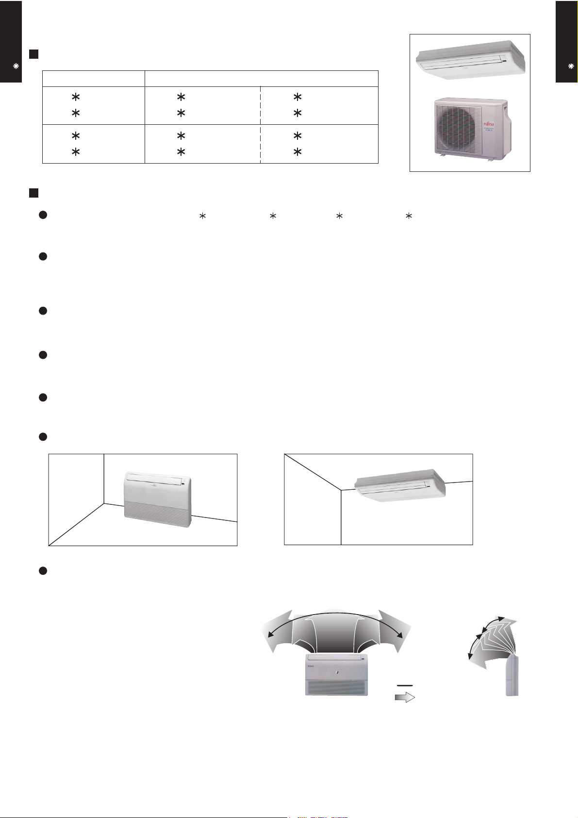
Flexible installation
FLOOR
CEILING
Double auto swing
Combination of up/down and right/left air
direction swing allows three-dimensional air
direction control.
Since up/down air direction flaps operate
automatically, according to the operating
mode of the unit, it is possible to set the air
direction based on the operating mode.
RIGHT and LEFT
swing
UP and DOWN
swing
5 steps selectable
- (01 - 01) -
Swing
Steps
7 steps selectable
Page 3

FUNCTION SETTING
FLOOR / CEILING TYPE
AB A18-24L
Filter sign operating time (Standard/long/short/no display)
Filter sign display time interval and filter sign no display can be selected.
Ceiling height (standard/high ceiling)
Air conditioner operation capacity (air flow) switching is possible as response to height of installation ceiling.
Cooling room temperature correction (Standard/low control)
Air conditioner control temperature can be switched to a little low as response to installation conditions.
Heating room temperature correction (Standard/low/slightly high/high control)
Air conditioning control temperature can be slightly adjusted as response to installation conditions.
Auto restart (ON/OFF)
ON/OFF of the function which automatically resets operation to the operation state before the power
interruption at power recovery when there was a power interruption during operation can be selected.
Room temperature sensing function (ON/OFF) only at wired remote controller connection
Sensor which controls the room temperature can be selected in two types: "Indoor sensor only" or
"Indoor sensor or wired remote controller sensor can be switched by remote controller operation".
FLOOR / CEILING TYPE
AB A18-24L
- (01 - 02) -
Page 4
1 2
2. REMOTE CONTROLLER
WIRELESS REMOTE CONTROLLER
FLOOR / CEILING TYPE
AB A18-24L
FEATURES
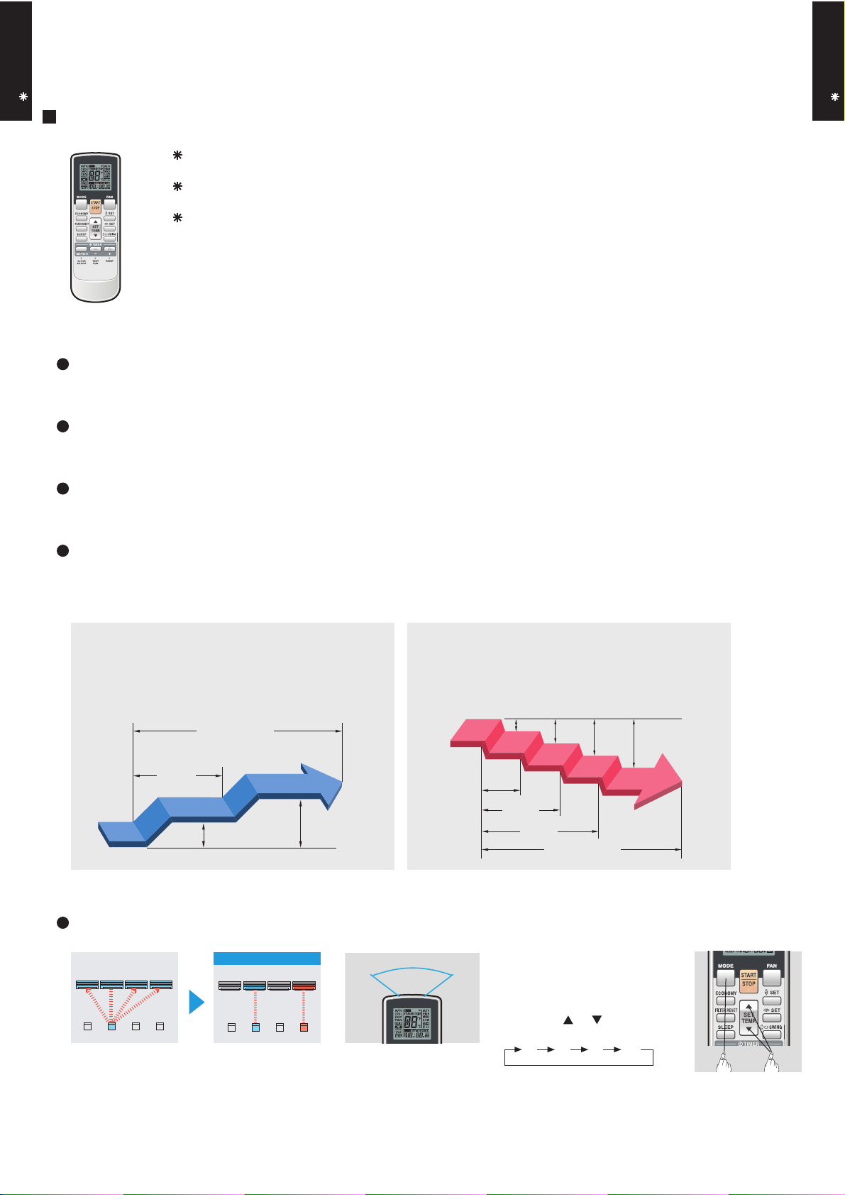
Four kinds of timer setup (ON / OFF / PROGRAM / SLEEP) are possible.
Four kinds of timers. Easy operation.
Easy to change transmission code (4 patterns) by button operation.
Simple function setting
Setting of the air conditioner selection function is performed by remote controller.
Built-in timers
Select from four different timer programs (On/Off/Program/Sleep).
FLOOR / CEILING TYPE
AB A18-24L
Program timer
The program timer operates the ON and OFF timer once within a 24 hour period.
Sleep timer
The sleep timer function automatically corrects the temperature thermostat setting according to the
time setting to prevent excessive cooling and heating while sleeping.
Cooling operation/dry operation
When the sleep timer is set, the set temperature
automatically rises 1 °C every hour. The set
temperature can rise up to a maximum of 2 °C.
Timer setting
60min.
1 °C
2 °C
Heating operation
When the sleep timer is set, the set temperature
automatically drops 1 °C every 30 minutes. The
set temperature can drop to a maximum of 4 °C.
1 °C
2 °C
3 °C
4 °C
30min.
60min.
90min.
Timer setting
Simultaneously operation
After code change
Mixed-up
• Code selector switch eliminates unit
being wrongly switched.
(Up to 4 codes can be set.)
A B C D
A B
C
1. Press the MODE button for
more than five seconds
to start the code change.
D
•Wide and precise
transmitting range.
- (01 - 03) -
2. Press the or button to
select the desired code.
A B C D
3. Press the MODE button
again to end the code change.
Page 5
FLOOR / CEILING TYPE
AB A18-24L
FUNCTIONS
1
3
2
4
5
11
13
16
10
14
12
15
FLOOR / CEILING TYPE
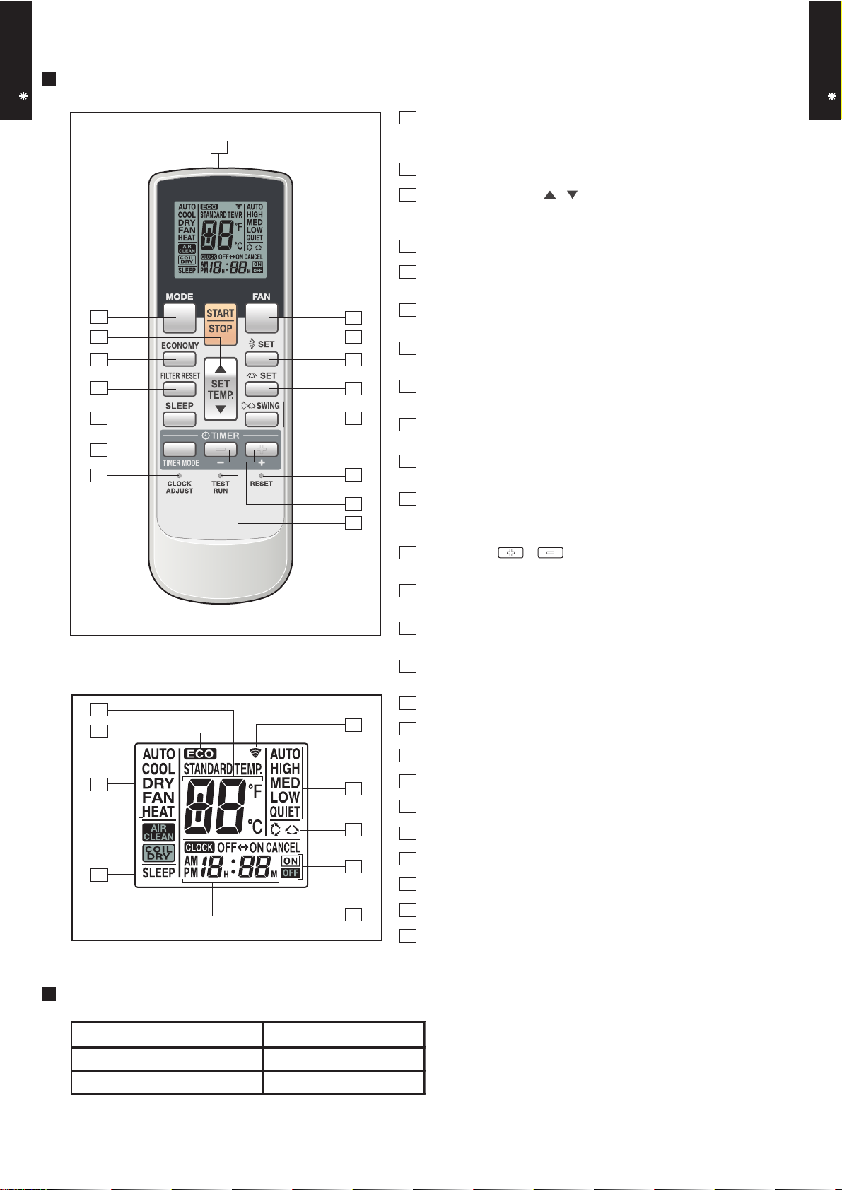
1
MODE button
Selects the operating mode (AUTO, HEAT, FAN, COOL, DRY).
/Start / end R.C. custom code change. (Max 4 types)
2
Economy button
3
Set temp. button ( / )
AB A18-24L
Set remote controller custom code buttons
Sets the indoor temp./ Sets R.C. custom code.
4
Filter reset button
5
Sleep button
Pressed to select sleep timer.
6
6
7
8
9
Fan button
Selects the fan speed (AUTO, QUIET, LOW, MED, HIGH).
7
START/STOP button
Pressed to start and stop operation.
8
Set button (Vertical)
Air flow direction vertical set button.
9
Set button (Horizontal)
Air flow direction horizontal set button.
10
Swing button
Air flow direction swing button.
11
Timer mode button
Pressed to select the timer mode. (OFF TIMER, ON TIMER,
PROGRAM TIMER, TIMER RESET)
Display panel
17
18
19
20
21
22
23
24
25
12
Timer set ( / ) button
Sets the current time and on-off time.
13
Clock adjust button
Sets the current time.
14
Reset button
Used when replacing batteries.
15
Test run button
Used when testing the air conditioner after installation.
16
Signal transmitter
17
Temperature set display
18
Economy display
19
Operating mode display
20
Sleep display
21
Transmit indicator
22
Fan speed display
23
Swing display
24
Timer mode display
25
Clock display
SPECIFICATION
SIZE (H x W x D mm) 170 x 56 x 19
WEIGHT ( g ) 85 (w/o batteries)
ACCESSORY Holder
- (01 - 04) -
Page 6
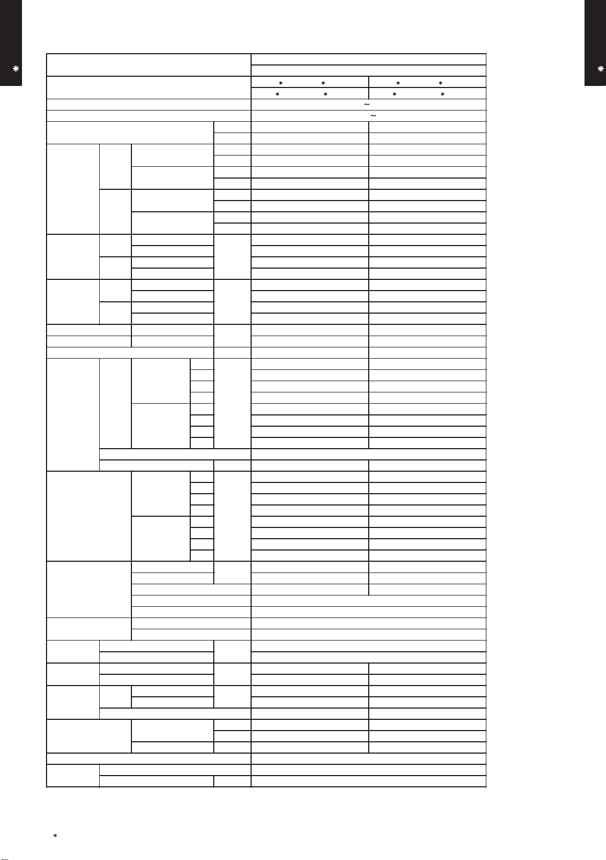
3. SPECIFICATIONS
AB A18-24L
FLOOR / CEILING TYPE
Type
Model name
Power source
Available voltage range
European energy label
Rated
Cooling
Min. - Max.
Capacity
Rated
Heating
Min. - Max.
Cooling
Input power
Heating
Cooling
Current
Heating
EER 3.21 3.21
COP 3.61 3.61
Moisture removal
Airflow
Fan
Sound pressure level
Heat exchanger type
Enclosure
Dimentions
( H× W ×D )
Weight
Connection pipe
Operation range
Remote controller type
Drain pipe
Note :
Specifications are based on the following conditions.
Cooling : Indoor temperature of 27 °CDB / 19 °CWB.and outdoor temperature of 35 °CDB/24 °CWB.
Heating : Indoor temperature of 20 °CDB / 15 °CWB.and outdoor temperature of 7 °CDB/6 °CWB.
Pipe length : 7.5 m, Height difference : 0 m.(Outdoor unit - Indoor unit)
The maximum current and the maximum input value are the maximum value when operated within the operation range(temperature).
rate
Type × Q'ty
Motor output W 80 80
Net
Gross
Net 27 ( 60 ) 27 ( 60 )
Gross 36 ( 79 ) 36 ( 79 )
Size mm
Method Flare Flare
Material
Size
Rated
*Max.
Rated
*Max.
Rated
*Max.
Rated
*Max.
Cooling
Heating
Cooling
Heating
Cooling
Heating
Dimensions (H × W × D) 252 × 800 × 39.9 252 × 800 × 53.2
Fin pitch 1.30 1.45
Rows x Stages 3 × 12 4 × 12
Pipe type
Fin type
Material
Colour
Liquid Φ6.35 (Φ 1/4 in.) Φ6.35 (Φ 1/4 in.)
Gas Φ 12.70 (Φ 1/2 in.) Φ 15.88 (Φ 5/8 in.)
Cooling
Heating °C 30 or less 30 or less
Cooling A A
Heating A A
kW 5.20 7.10
BTU/h 17700 24200
kW 0.90-5.90 0.90-8.00
BTU/h 3100-20100 3100-27300
kW 6.00 8.00
BTU/h 20500 27300
kW 0.90-7.50 0.90-9.10
BTU/h 3100-25600 3100-31000
kW
A
kW/kW
l/h (pints/h) 2.0 ( 3.5 ) 2.7 ( 4.8 )
High 780 980
Med 700 820
Low 560 680
Quiet 500 540
Quiet 500 540
Quiet 32(Floor console) , 31(Under ceiling) 36(Floor console) , 35(Under ceiling)
Quiet 32(Floor console) , 31(Under ceiling) 36(Floor console) , 35(Under ceiling)
m3/h
High 780 980
Med 700 820
Low 560 680
High 44(Floor console) , 43(Under ceiling) 49(Floor console) , 48(Under ceiling)
Med 41(Floor console) , 40(Under ceiling) 45(Floor console) , 44(Under ceiling)
Low 35(Floor console) , 34(Under ceiling) 41(Floor console) , 40(Under ceiling)
dB(A)
High 44(Floor console) , 43(Under ceiling) 49(Floor console) , 48(Under ceiling)
Med 41(Floor console) , 40(Under ceiling) 45(Floor console) , 44(Under ceiling)
Low 35(Floor console) , 34(Under ceiling) 41(Floor console) , 40(Under ceiling)
mm
mm
kg(lb.)
°C 18 to 32 18 to 32
%RH 80 or less 80 or less
mm
AB A18LAT, AB F18LAT
AO A18LACL, AO A18LALL AO A24LACL, AO A24LALL
FLOOR CEILING MODEL
INVERTER HEATPUMP
AB A24LAT, AB F24LAT
230V 50Hz
198-264V 50Hz
1.62 2.21
2.16 2.85
1.66 2.21
2.96 3.19
7.1 9.7
9.0 12.0
7.3 9.7
12.5 13.5
Sirocco × 2
Copper
Aluminium
ABS
White
199 × 990 × 655
324 × 1075 × 686
Wireless
ABS
Outer diameter : 26.0 / Inner diameter : 21.5
AB A18-24L
FLOOR / CEILING TYPE
- (01 - 05) -
Page 7
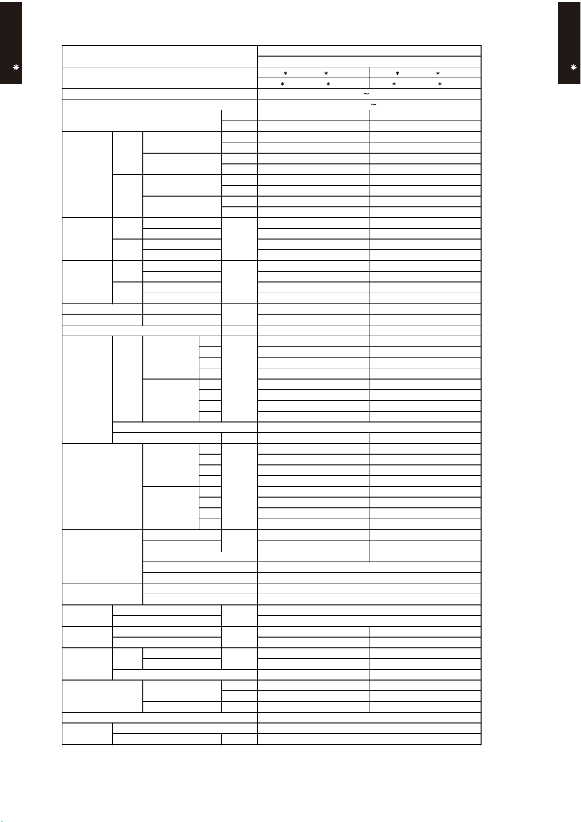
Model name
Type
Drain pipe
Material
ABS
Size
Outer diameter : 26.0 / Inner diameter : 21.5
Operation range
Cooling
Remote controller type
Wireless
Weight
kg(lb.)
Connection pipe
Size
mm
Enclosure
ABS
White
Dimentions
( H× W ×D )
mm
199 × 990 × 655
324 × 1075 × 686
Heat exchanger type
mm
Copper
Aluminium
Sirocco × 2
Sound pressure level
Cooling
dB(A)
Heating
Fan
Airflow
rate
Cooling
m3/h
Heating
Cooling
kW/kW
Heating
Moisture removal
Current
Cooling
Rated
A
*Max.
Heating
Rated
*Max.
Input power
Cooling
Rated
kW
*Max.
Heating
Rated
*Max.
European energy label
Capacity
Cooling
Rated
Min. - Max.
Heating
Rated
Min. - Max.
Power source
230V 50Hz
Available voltage range
198-264V 50Hz
FLOOR CEILING MODEL
INVERTER HEATPUMP
AB A18-24L
FLOOR / CEILING TYPE
AB A18LAT, AB F18LAT
AO B18LACL, AO B18LALL AO B24LACL, AO B24LALL
Cooling B B
Heating B B
kW 5.20 7.10
BTU/h 17700 24200
kW 0.90-5.70 0.90-7.80
BTU/h 3100-19500 3100-26600
kW 6.00 8.00
BTU/h 20500 27300
kW 0.90-7.20 0.90-8.80
BTU/h 3100-24600 3100-30000
1.70 2.32
2.16 2.85
1.75 2.33
2.96 3.19
7.4 10.1
9.0 12.0
7.7 10.2
12.5 13.5
EER 3.06 3.06
COP 3.43 3.43
l/h (pints/h) 2.0 ( 3.5 ) 2.7 ( 4.8 )
High 780 980
Med 700 820
Low 560 680
Quiet 500 540
High 780 980
Med 700 820
Low 560 680
Quiet 500 540
Type × Q'ty
Motor output W 80 80
High 44(Floor console) , 43(Under ceiling) 49(Floor console) , 48(Under ceiling)
Med 41(Floor console) , 40(Under ceiling) 45(Floor console) , 44(Under ceiling)
Low 35(Floor console) , 34(Under ceiling) 41(Floor console) , 40(Under ceiling)
Quiet 32(Floor console) , 31(Under ceiling) 36(Floor console) , 35(Under ceiling)
Dimensions (H × W × D) 252 × 800 × 39.9 252 × 800 × 53.2
Fin pitch 1.30 1.45
Rows x Stages 3 × 12 4 × 12
Pipe type
Fin type
Material
Colour
Net
Gross
Net 27 ( 60 ) 27 ( 60 )
Gross 36 ( 79 ) 36 ( 79 )
Liquid Φ6.35 (Φ 1/4 in.) Φ6.35 (Φ 1/4 in.)
Gas Φ 12.70 (Φ 1/2 in.) Φ 15.88 (Φ 5/8 in.)
Method Flare Flare
°C 18 to 32 18 to 32
%RH 80 or less 80 or less
Heating °C 30 or less 30 or less
AB A24LAT, AB F24LAT
AB A18-24L
FLOOR / CEILING TYPE
mm
Note :
Specifications are based on the following conditions.
Cooling : Indoor temperature of 27 °CDB / 19 °CWB.and outdoor temperature of 35 °CDB/24°CWB.
Heating : Indoor temperature of 20 °CDB / 15 °CWB.and outdoor temperature of 7 °CDB/6 °CWB.
Pipe length : 7.5 m, Height difference : 0 m.(Outdoor unit - Indoor unit)
*The maximum current and the maximum input value are the maximum value when operated within the operation range(temperature)
- (01 - 06) -
Page 8
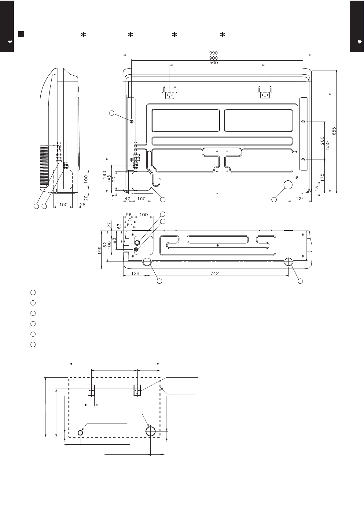
4. DIMENSIONS
MODEL : AB A18L, AB F18L, AB A24L, AB F24L
AB A18-24L
FLOOR / CEILING TYPE
(Unit : mm)
AB A18-24L
FLOOR / CEILING TYPE
6
1 2
Side view
1
Refrigerant piping flare connection (Gas)
2
Refrigerant piping flare connection (Liquid)
3
Drain piping connection
4
Knock out hole for drain piping
5
Knock out hole for refrigerant piping
6
Hole for lifting bolt (Use M10 screw bolt)
990
500 245
1
2
3
Wall bracket
Rear view
Bottom view
45
3
655
530
Side of set
65
100 hole
50 hole
45
65
125
100 hole
- (01 - 07) -
Page 9
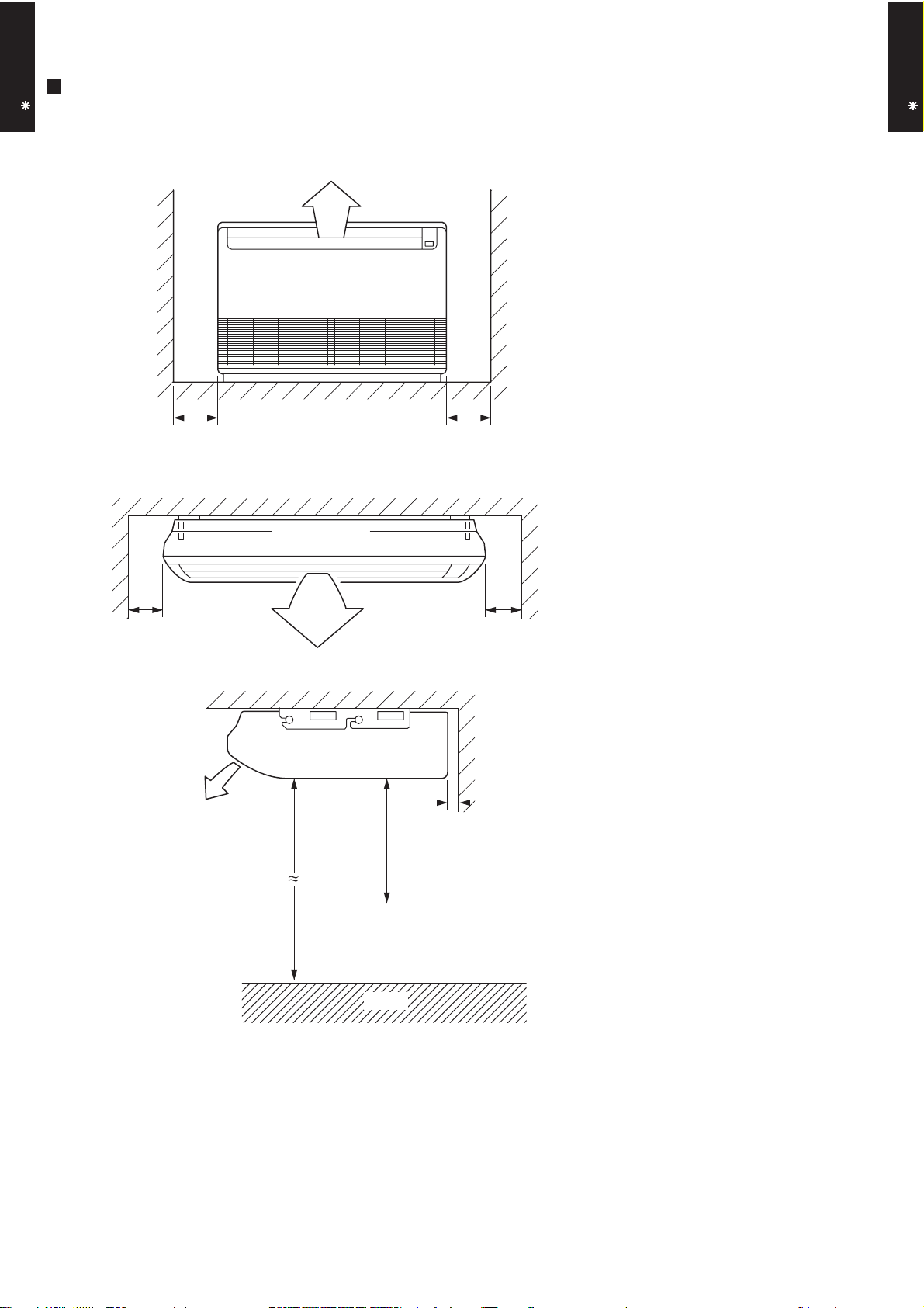
Floor
FLOOR / CEILING TYPE
AB A18-24L
MOUNTING POSITION
Left Right
Ceiling
(Unit : mm)
300 or more300 or more
FLOOR / CEILING TYPE
AB A18-24L
Left
150 or more 300 or more
Indoor unit
Ceiling
2300 or more
Obstruction
20 or more
1000 or more
Right
- (01 - 08) -
Page 10
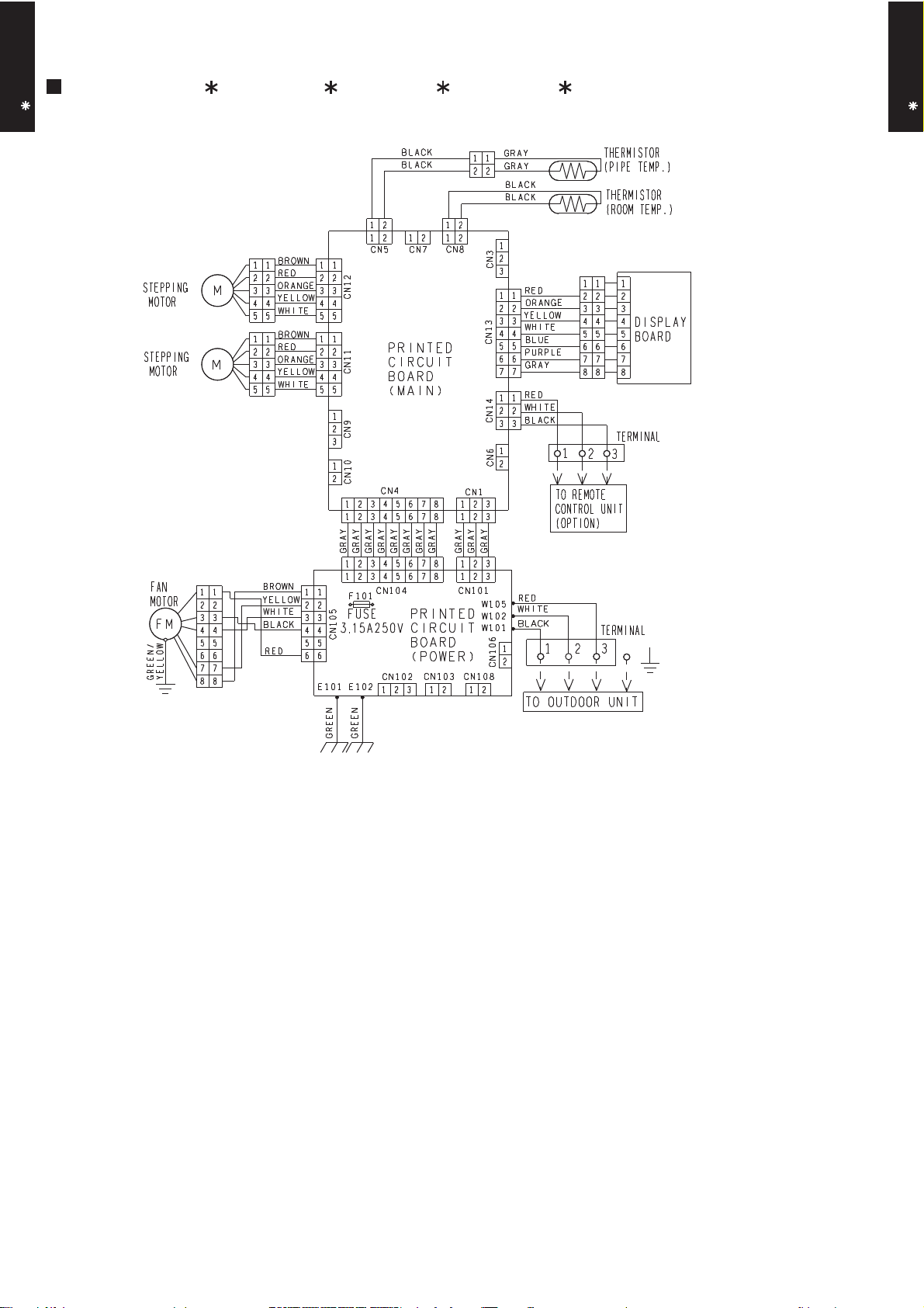
5. WIRING DIAGRAMS
MODEL : AB A18L, AB F18L, AB A24L, AB F24L
AB A18-24L
FLOOR / CEILING TYPE
AB A18-24L
FLOOR / CEILING TYPE
- (01 - 09) -
Page 11
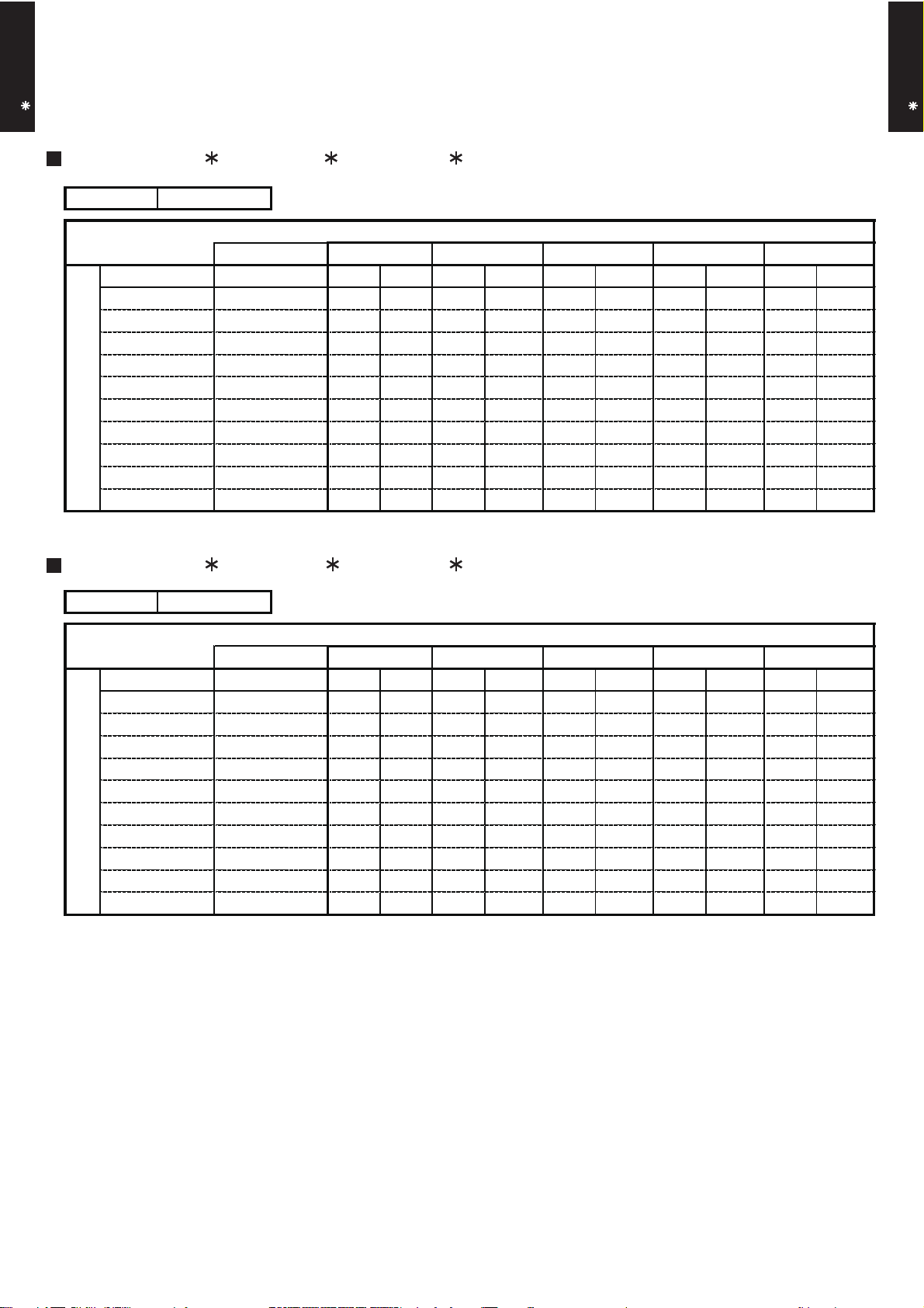
6. CAPACITY TABLE
AB A18-24L
FLOOR / CEILING TYPE
6-1. COOLING CAPACITY
This table is created using the maximum capacity.
MODEL : AB A18L, AB F18L / AO A18L
AFR 13.3
°CDB
°CWB
°CDB
-10
0
5
10
15
20
25
30
Outdoor temperature
35
40
46
18 21 23 25 27 29 32
12 15 16 18
TC SHC PI TC SHC PI TC SHC PI TC SHC PI TC S HC PI TC SHC PI TC SHC PI
4.35 3.28 0.39 4.84 3.30 0.40 5.01 3.59 0.40 5.34 3.60 0.40 5.50 3.89 0.40 5.83 3.88 0.41 6.17 4.13 0.41
4.26 3.24 0.46 4.74 3.26 0.46 4.90 3.54 0.47 5.23 3.56 0.47 5.39 3.84 0.47 5.71 3.83 0.48 6.04 4.07 0.48
4.14 3.18 0.57 4.61 3.20 0.58 4.77 3.48 0.58 5.08 3.49 0.59 5.24 3.77 0.59 5.55 3.76 0.60 5.86 4.00 0.60
4.00 3.12 0.68 4.45 3.14 0.69 4.61 3.41 0.70 4.91 3.42 0.70 5.06 3.70 0.71 5.37 3.68 0.71 5.67 3.92 0.72
4.04 3.14 0.59 4.50 3.16 0.60 4.65 3.43 0.61 4.95 3.44 0.61 5.11 3.72 0.62 5.41 3.70 0.62 5.72 3.94 0.63
5.16 3.68 1.28 5.75 3.70 1.30 5.95 4.03 1.31 6.34 4.04 1.32 6.54 4.36 1.33 6.93 4.34 1.34 7.32 4.63 1.35
4.94 3.57 1.43 5.51 3.59 1.46 5.70 3.91 1.46 6.07 3.92 1.48 6.26 4.23 1.49 6.63 4.22 1.50 7.01 4.49 1.52
4.71 3.46 1.59 5.25 3.48 1.61 5.43 3.78 1.62 5.78 3.79 1.64 5.96 4.10 1.65 6.32 4.08 1.66 6.68 4.35 1.68
4.66 3.43 1.88 5.19 3.46 1.91 5.37 3.76 1.92 5.72 3.77 1.94 5.90 4.07 1.95 6.25 4.05 1.97 6.61 4.32 1.99
3.53 2.90 1.34 3.93 2.92 1.36 4.06 3.18 1.36 4.33 3.19 1.38 4.46 3.44 1.38 4.73 3.43 1.40 5.00 3.65 1.41
2.50 2.46 1.01 2.79 2.47 1.02 2.88 2.69 1.03 3.07 2.69 1.04 3.17 2.91 1.05 3.36 2.90 1.06 3.55 3.09 1.07
MODEL : AB A18L, AB F18L / AO B18L
AFR 13.3
°CDB
°CWB
°CDB
-10
0
e
r
5
u
at
r
10
pe
15
em
20
r t
25
doo
ut
30
O
35
40
46
12
TC SHC PI TC SHC PI TC SHC PI TC SHC PI TC S HC PI TC SHC PI TC SHC PI
4.35 3.28 0.39 4.84 3.30 0.40 5.01 3.59 0.40 5.34 3.60 0.40 5.50 3.89 0.40 5.83 3.88 0.41 6.17 4.13 0.41
4.26 3.24 0.46 4.74 3.26 0.46 4.90 3.54 0.47 5.23 3.56 0.47 5.39 3.84 0.47 5.71 3.83 0.48 6.04 4.07 0.48
4.14 3.18 0.57 4.61 3.20 0.58 4.77 3.48 0.58 5.08 3.49 0.59 5.24 3.77 0.59 5.55 3.76 0.60 5.86 4.00 0.60
4.00 3.12 0.68 4.45 3.14 0.69 4.61 3.41 0.70 4.91 3.42 0.70 5.06 3.70 0.71 5.37 3.68 0.71 5.67 3.92 0.72
4.04 3.14 0.59 4.50 3.16 0.60 4.65 3.43 0.61 4.95 3.44 0.61 5.11 3.72 0.62 5.41 3.70 0.62 5.72 3.94 0.63
5.16 3.68 1.28 5.75 3.70 1.30 5.95 4.03 1.31 6.34 4.04 1.32 6.54 4.36 1.33 6.93 4.34 1.34 7.32 4.63 1.35
4.94 3.57 1.43 5.51 3.59 1.46 5.70 3.91 1.46 6.07 3.92 1.48 6.26 4.23 1.49 6.63 4.22 1.50 7.01 4.49 1.52
4.71 3.46 1.59 5.25 3.48 1.61 5.43 3.78 1.62 5.78 3.79 1.64 5.96 4.10 1.65 6.32 4.08 1.66 6.68 4.35 1.68
4.50 3.27 1.88 5.02 3.28 1.91 5.19 3.57 1.92 5.53 3.58 1.94 5.70 3.87 1.95 6.04 3.85 1.97 6.38 4.10 1.99
3.41 2.78 1.34 3.80 2.79 1.36 3.92 3.04 1.36 4.18 3.05 1.38 4.31 3.29 1.38 4.57 3.28 1.40 4.83 3.49 1.41
2.42 2.36 1.01 2.69 2.38 1.02 2.79 2.59 1.03 2.97 2.59 1.04 3.06 2.80 1.05 3.24 2.79 1.06 3.43 2.97 1.07
15
23 2518 21
16 18
Indoor temperature
Indoor temperature
19 21 23
27 29 32
AB A18-24L
FLOOR / CEILING TYPE
2319 21
AFR: Air Flow Rate (m3/min)
TC : Total Capacity (kW)
SHC: Sensible Heat Capacity (kW)
PI : Power Input (kW)
- (01 - 10) -
Page 12
AB A18-24L
FLOOR / CEILING TYPE
MODEL : AB A24L, AB F24L / AO A24L
AFR 15.3
°CDB
°CWB
°CDB
-10
0
5
10
15
20
25
30
Outdoor temperature
35
40
46
18 21 23 25 27 29 32
12 15 16 18 19 21 23
TC SHC PI TC SHC PI TC SHC PI TC SHC PI TC S HC PI TC SHC PI TC SHC PI
5.79 4.65 0.60 6.46 4.67 0.61 6.68 5.08 0.61 7.12 5.10 0.62 7.34 5.51 0.62 7.78 5.48 0.63 8.22 5.84 0.63
5.69 4.59 0.64 6.34 4.62 0.65 6.55 5.02 0.65 6.98 5.04 0.66 7.20 5.44 0.66 7.63 5.42 0.67 8.06 5.77 0.68
5.49 4.49 0.78 6.12 4.52 0.79 6.33 4.91 0.79 6.74 4.93 0.80 6.95 5.32 0.81 7.37 5.30 0.81 7.79 5.64 0.82
5.28 4.38 0.91 5.88 4.40 0.92 6.08 4.79 0.93 6.48 4.80 0.94 6.68 5.19 0.94 7.08 5.17 0.95 7.48 5.50 0.96
5.39 4.44 0.76 6.01 4.47 0.77 6.21 4.85 0.77 6.62 4.87 0.78 6.83 5.26 0.79 7.24 5.24 0.79 7.65 5.58 0.80
6.85 5.22 1.61 7.63 5.25 1.64 7.89 5.71 1.64 8.41 5.73 1.66 8.67 6.18 1.67 9.19 6.16 1.69 9.71 6.56 1.70
6.53 5.04 1.80 7.27 5.07 1.82 7.52 5.51 1.83 8.01 5.52 1.85 8.26 5.97 1.86 8.76 5.94 1.88 9.25 6.33 1.90
6.18 4.86 2.00 6.89 4.88 2.03 7.12 5.31 2.04 7.59 5.33 2.06 7.83 5.75 2.07 8.30 5.73 2.09 8.77 6.10 2.11
6.32 4.93 2.47 7.04 4.96 2.51 7.28 5.39 2.52 7.76 5.41 2.55 8.00 5.84 2.56 8.48 5.82 2.59 8.96 6.20 2.61
5.21 4.34 2.05 5.81 4.37 2.08 6.01 4.75 2.09 6.40 4.77 2.11 6.60 5.15 2.12 7.00 5.13 2.14 7.39 5.46 2.16
3.77 3.62 1.55 4.20 3.64 1.57 4.35 3.96 1.58 4.63 3.97 1.60 4.78 4.29 1.61 5.06 4.27 1.62 5.35 4.55 1.64
Indoor temperature
MODEL : AB A24L, AB F24L / AO B24L
AFR 15.3
°CDB
°CWB
°CDB
-10
0
re
5
u
at
10
er
p
15
em
20
or t
25
do
ut
30
O
35
40
46
18 21
12
TC SHC PI TC SHC PI TC SHC PI TC SHC PI TC S HC PI TC SHC PI TC SHC PI
15 16 18
5.79 4.65 0.60 6.46 4.67 0.61 6.68 5.08 0.61 7.12 5.10 0.62 7.34 5.51 0.62 7.78 5.48 0.63 8.22 5.84 0.63
5.69 4.59 0.64 6.34 4.62 0.65 6.55 5.02 0.65 6.98 5.04 0.66 7.20 5.44 0.66 7.63 5.42 0.67 8.06 5.77 0.68
5.49 4.49 0.78 6.12 4.52 0.79 6.33 4.91 0.79 6.74 4.93 0.80 6.95 5.32 0.81 7.37 5.30 0.81 7.79 5.64 0.82
5.28 4.38 0.91 5.88 4.40 0.92 6.08 4.79 0.93 6.48 4.80 0.94 6.68 5.19 0.94 7.08 5.17 0.95 7.48 5.50 0.96
5.39 4.44 0.76 6.01 4.47 0.77 6.21 4.85 0.77 6.62 4.87 0.78 6.83 5.26 0.79 7.24 5.24 0.79 7.65 5.58 0.80
6.85 5.22 1.61 7.63 5.25 1.64 7.89 5.71 1.64 8.41 5.73 1.66 8.67 6.18 1.67 9.19 6.16 1.69 9.71 6.56 1.70
6.53 5.04 1.80 7.27 5.07 1.82 7.52 5.51 1.83 8.01 5.52 1.85 8.26 5.97 1.86 8.76 5.94 1.88 9.25 6.33 1.90
6.18 4.86 2.00 6.89 4.88 2.03 7.12 5.31 2.04 7.59 5.33 2.06 7.83 5.75 2.07 8.30 5.73 2.09 8.77 6.10 2.11
6.16 4.76 2.47 6.86 4.79 2.51 7.10 5.21 2.52 7.57 5.23 2.55 7.80 5.64 2.56 8.27 5.62 2.59 8.74 5.99 2.61
5.08 4.21 2.05 5.66 4.23 2.08 5.86 4.60 2.09 6.24 4.61 2.11 6.43 4.98 2.12 6.82 4.96 2.14 7.21 5.29 2.16
3.68 3.52 1.55 4.10 3.54 1.57 4.24 3.85 1.58 4.52 3.86 1.60 4.66 4.17 1.61 4.94 4.15 1.62 5.22 4.42 1.64
Indoor temperature
27 2923 25 32
AB A18-24L
FLOOR / CEILING TYPE
2319 21
AFR: Air Flow Rate (m3/min)
TC : Total Capacity (kW)
SHC: Sensible Heat Capacity (kW)
PI : Power Input (kW)
- (01 - 11) -
Page 13
6-2. HEATING CAPACITY
AB A18-24L
FLOOR / CEILING TYPE
This table is created using the maximum capacity.
MODEL : AB A18L, AB F18L / AO A18L
AFR 13.3
°CDB 16 18 20 22 24
°CDB °CWB
-15 -16
-10 -11
-5 -7
0 -2
5 3
7 6
10 8
Outdoor temperature
15 10
20 15
24 18
TC PI TC PI TC PI TC PI TC PI
5.25 2.15 5.13 2.20 5.00 2.24 4.88 2.29 4.75 2.33
5.90 2.27 5.76 2.32 5.62 2.37 5.48 2.42 5.34 2.46
6.57 2.40 6.41 2.45 6.26 2.50 6.10 2.55 5.94 2.60
7.46 2.57 7.28 2.62 7.10 2.68 6.93 2.73 6.75 2.78
8.18 2.65 7.98 2.70 7.79 2.76 7.59 2.81 7.40 2.87
7.88 2.26 7.69 2.30 7.50 2.35 7.31 2.40 7.13 2.44
8.15 2.31 7.96 2.35 7.77 2.40 7.57 2.45 7.38 2.50
7.70 1.97 7.52 2.01 7.33 2.05 7.15 2.09 6.97 2.13
7.23 1.58 7.06 1.62 6.88 1.65 6.71 1.68 6.54 1.72
7.43 1.59 7.25 1.62 7.07 1.65 6.90 1.68 6.72 1.72
MODEL : AB A18L, AB F18L / AO B18L
Indoor temperature
AB A18-24L
FLOOR / CEILING TYPE
AFR
°CDB °CWB
-15
re
u
t
Outdoor tempera
AFR: Air Flow Rate (m3/min)
TC : Total Capacity (kW)
PI : Power Input (kW)
-10
-5
0 -2
5
7
10
15 10
20
24
13.3
°CDB
-16
-11
-7
3
6
8
15
18
Indoor temperature
16 18 20 22
TC PI TC PI TC PI TC PI TC PI
5.25 2.15 5.13 2.20 5.00 2.24 4.88 2.29 4.75 2.33
5.90 2.27 5.76 2.32 5.62 2.37 5.48 2.42 5.34 2.46
6.57 2.40 6.41 2.45 6.26 2.50 6.10 2.55 5.94 2.60
7.46 2.57 7.28 2.62 7.10 2.68 6.93 2.73 6.75 2.78
7.85 2.65 7.66 2.70 7.48 2.76 7.29 2.81 7.10 2.87
7.56 2.26 7.38 2.30 7.20 2.35 7.02 2.40 6.84 2.44
7.83 2.31 7.64 2.35 7.45 2.40 7.27 2.45 7.08 2.50
7.39 1.97 7.22 2.01 7.04 2.05 6.87 2.09 6.69 2.13
6.94 1.58 6.77 1.62 6.61 1.65 6.44 1.68 6.28 1.72
7.13 1.59 6.96 1.62 6.79 1.65 6.62 1.68 6.45 1.72
24
- (01 - 12) -
Page 14
AB A18-24L
FLOOR / CEILING TYPE
MODEL : AB A24L, AB F24L / AO A24L
AFR 15.3
°CDB 16 18 20
°CDB °CWB
-15
-16
-10 -11
-5 -7
0 -2
5 3
7 6
10 8
Outdoor temperature
15 10
20 15
24 18
TC PI TC PI TC PI TC PI TC PI
6.15 2.70 6.00 2.76 5.86 2.82 5.71 2.87 5.57 2.93
6.93 2.87 6.76 2.93 6.60 2.99 6.43 3.05 6.27 3.11
7.64 2.86 7.46 2.91 7.28 2.97 7.10 3.03 6.92 3.09
8.59 2.84 8.39 2.90 8.18 2.96 7.98 3.01 7.77 3.07
9.55 2.86 9.32 2.91 9.09 2.97 8.86 3.03 8.64 3.09
9.56 2.54 9.33 2.60 9.10 2.65 8.87 2.70 8.65 2.76
9.86 2.55 9.63 2.60 9.39 2.65 9.16 2.71 8.92 2.76
8.97 1.99 8.75 2.03 8.54 2.07 8.33 2.12 8.11 2.16
8.22 1.54 8.03 1.57 7.83 1.60 7.64 1.63 7.44 1.66
8.52 1.54 8.32 1.57 8.12 1.60 7.91 1.63 7.71 1.66
MODEL : AB A24L, AB F24L / AO B24L
Indoor temperature
22 24
AB A18-24L
FLOOR / CEILING TYPE
AFR
°CDB °CWB
-15
re
atu
-10
-5
0 -2
mper
e
t
or
do
ut
O
5
7
10
15 10
20
24
AFR: Air Flow Rate (m3/min)
TC : Total Capacity (kW)
PI : Power Input (kW)
15.3
°CDB
-16
-11
-7
3
6
8
15
18
Indoor temperature
2416 18 20 22
TC PI TC PI TC PI TC PI TC PI
6.15 2.70 6.00 2.76 5.86 2.82 5.71 2.87 5.57 2.93
6.70 2.87 6.54 2.93 6.38 2.99 6.22 3.05 6.06 3.11
7.39 2.86 7.22 2.91 7.04 2.97 6.86 3.03 6.69 3.09
8.31 2.84 8.11 2.90 7.91 2.96 7.71 3.01 7.52 3.07
9.23 2.86 9.01 2.91 8.79 2.97 8.57 3.03 8.35 3.09
9.24 2.54 9.02 2.60 8.80 2.65 8.58 2.70 8.36 2.76
9.54 2.55 9.31 2.60 9.08 2.65 8.86 2.71 8.63 2.76
8.67 1.99 8.46 2.03 8.26 2.07 8.05 2.12 7.84 2.16
7.95 1.54 7.76 1.57 7.57 1.60 7.38 1.63 7.19 1.66
8.24 1.54 8.04 1.57 7.85 1.60 7.65 1.63 7.46 1.66
- (01 - 13) -
Page 15
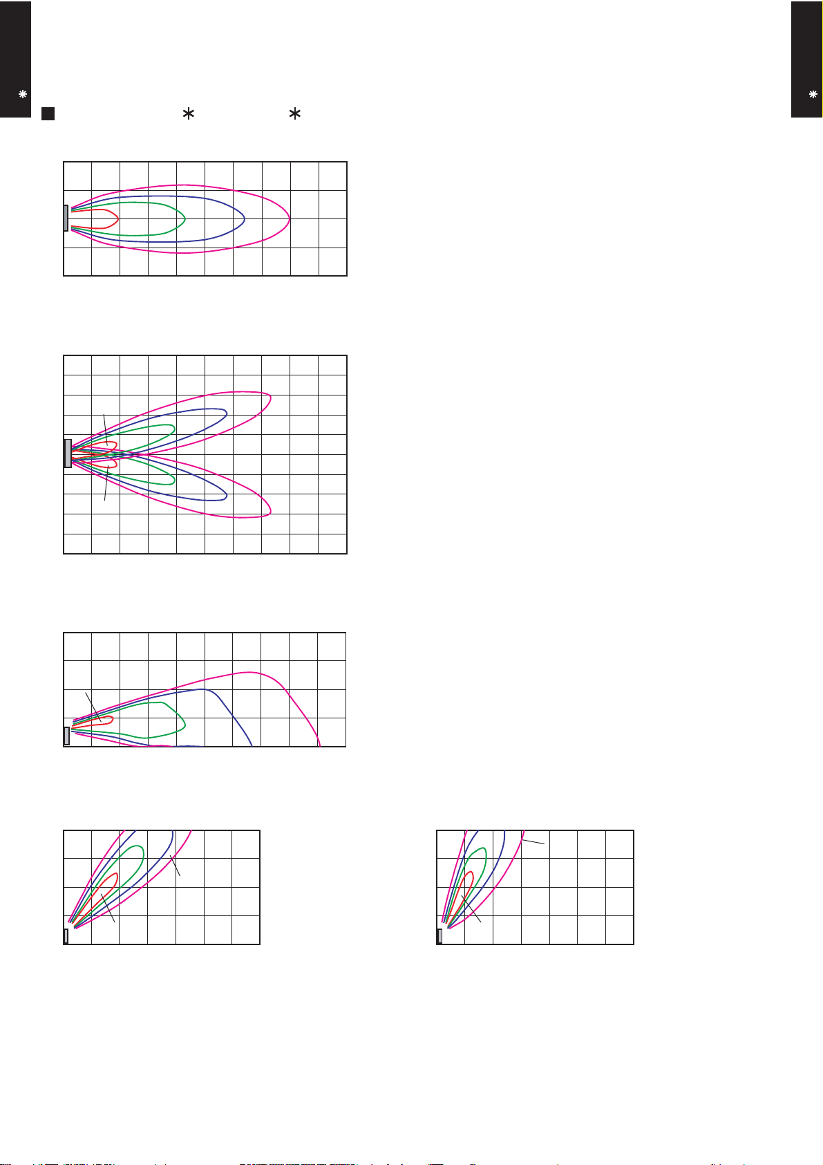
7. FAN PERFORMANCE
7-1. AIR VELOCITY DISTRIBUTION
AB A18-24L
FLOOR / CEILING TYPE
MODEL : AB A18L, AB F18L (FLOOR CONSOLE)
0.25
Unit : m/s
0.25
Unit : m/s
Right
Left
TOP VIEW
VERTICAL FLAP : Downward
HORIZONTAL FLAP : Center
(m)
TOP VIEW
VERTICAL FLAP : Downward
HORIZONTAL FLAP : Right & Left
(m)
(m)
2
1
0
1
2
0.5
1
2
0 1 2 3 4 5 6 7 8 9 10
(m)
5
4
3
2
1
2
0.5
1
0.25
0
1
2
3
1
0.5
2
4
5
0 1 2 3 4 5 6 7 8 9 10
AB A18-24L
FLOOR / CEILING TYPE
0
(m)
4
Unit : m/s
3
2
2
1
0
0 1 2 3 4 5 6 7 8 9 10
(m)
4
3
1
1
2
0.5
Unit : m/s
0.5
0.25
1
0
0 1 2 3 4 5 6 7
2
0.25
SIDE VIEW
VERTICAL FLAP : Center
HORIZONTAL FLAP : Center
(m)
SIDE VIEW
VERTICAL FLAP : Downward
HORIZONTAL FLAP : Center
(m)
(m)
4
3
2
1
0
0 1 2 3 4 5 6 7
0.5
1
2
Unit : m/s
0.25
SIDE VIEW
VERTICAL FLAP : Upward
HORIZONTAL FLAP : Center
(m)
- (01 - 14) -
Page 16
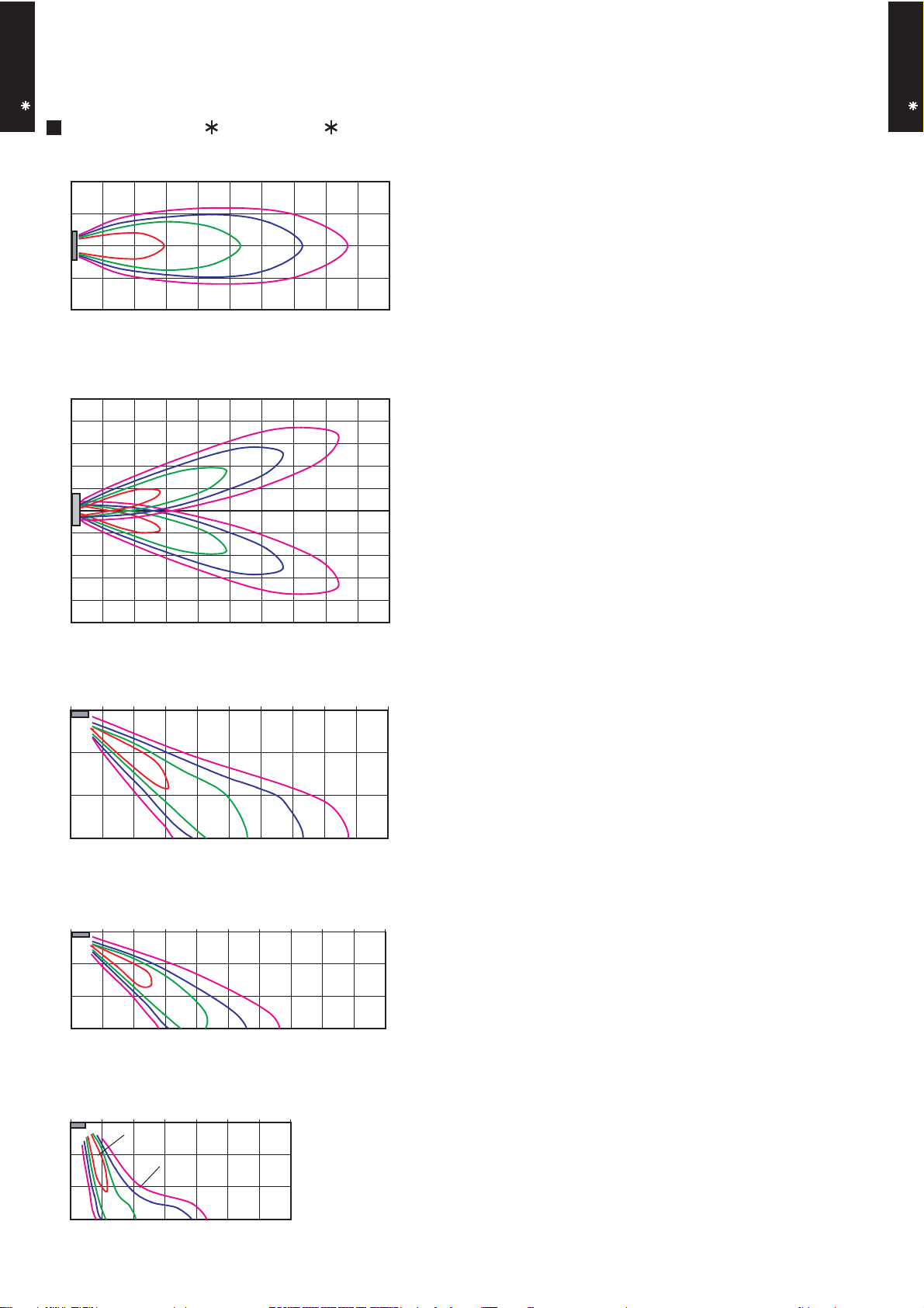
AB A18-24L
FLOOR / CEILING TYPE
MODEL : AB A18L, AB F18L (UNDER CEILING)
AB A18-24L
FLOOR / CEILING TYPE
(m)
2
Unit : m/s
1
0
2
1
0.5
0.25
1
2
0 1 2 3 4 5 6 7 8 9 10
(m)
5
Unit : m/s
4
3
2
1
1
2
0.5
0.25
0
1
2
3
4
2
1
0.5
0.25
5
0 1 2 3 4 5 6 7 8 9 10
TOP VIEW
VERTICAL FLAP : Upward
HORIZONTAL FLAP : Center
(m)
TOP VIEW
VERTICAL FLAP : Upward
HORIZONTAL FLAP : Right & Left
(m)
0
(m)
3
Unit : m/s
2
2
1
1
0.5 0.25
0
0 1 2 3 4 5 6 7 8 9 10
(m)
3
Unit : m/s
2
2
1
0
0 1 2 3 4 5 6 7 8 9 10
(m)
3
2
1
2
0.25
1
1
0
0 1 2 3 4 5 6 7
0.5
0.25
0.5
Unit : m/s
SIDE VIEW
VERTICAL FLAP : Downward
HORIZONTAL FLAP : Center
(m)
SIDE VIEW
VERTICAL FLAP : Upward
HORIZONTAL FLAP : Center
(m)
SIDE VIEW
VERTICAL FLAP : Center
HORIZONTAL FLAP : Center
(m)
- (01 - 15) -
Page 17
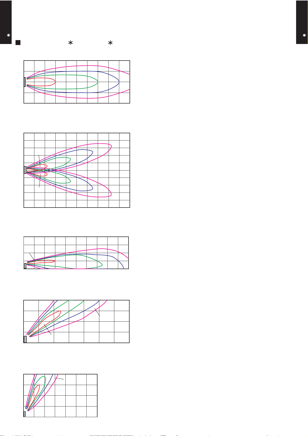
AB A18-24L
FLOOR / CEILING TYPE
MODEL : AB A24L, AB F24L (FLOOR CONSOLE)
AB A18-24L
FLOOR / CEILING TYPE
(m)
2
Unit : m/s
1
0
2
1
0.5
1
2
0 1 2 3 4 5 6 7 8 9 10
(m)
5
4
3
2
1
2
1
0.5
Unit : m/s
Right
0.25
0
1
2
3
2
4
5
1
0.5
0.25
Left
0 1 2 3 4 5 6 7 8 9 10
0.25
TOP VIEW
VERTICAL FLAP : Downward
HORIZONTAL FLAP : Center
(m)
TOP VIEW
VERTICAL FLAP : Downward
HORIZONTAL FLAP : Right & Left
(m)
0
(m)
4
Unit : m/s
3
2
2
1
1
0.25
0.5
0
(m)
4
1
0.5
Unit : m/s
3
2
0.25
1
2
0
0 1 2 3 4 5 6 7
(m)
4
3
0.5
1
2
Unit : m/s
0.25
2
SIDE VIEW
VERTICAL FLAP : Downward
HORIZONTAL FLAP : Center
(m)
100 1 2 3 4 5 6 7 8 9
SIDE VIEW
VERTICAL FLAP : Center
HORIZONTAL FLAP : Center
(m)
1
0
0 1 2 3 4 5 6 7
SIDE VIEW
VERTICAL FLAP : Upward
HORIZONTAL FLAP : Center
(m)
- (01 - 16) -
Page 18

AB A18-24L
FLOOR / CEILING TYPE
MODEL : AB A24L, AB F24L (UNDER CEILING)
AB A18-24L
FLOOR / CEILING TYPE
(m)
2
Unit : m/s
1
0
2 1
0.5
0.25
1
2
0 1 2 3 4 5 6 7 8 9 10
(m)
5
4
3
2
1
2
1
Unit : m/s
0.25
0.5
0
1
2
3
4
2
1
0.5
0.25
5
0 1 2 3 4 5 6 7 8 9 10
TOP VIEW
VERTICAL FLAP : Upward
HORIZONTAL FLAP : Center
(m)
TOP VIEW
VERTICAL FLAP : Upward
HORIZONTAL FLAP : Right & Left
(m)
(m)
3
Unit : m/s
2
2
1
1
0.5
0.25
0
0 1 2 3 4 5 6 7 8 9 10
(m)
(m)
3
Unit : m/s
2
2
1
0
1
0.5
0.25
0 1 2 3 4 5 6 7 8 9 10
(m)
3
2
2
0.25
1
1
0
0.5
0 1 2 3 4 5 6 7
Unit : m/s
SIDE VIEW
VERTICAL FLAP : Downward
HORIZONTAL FLAP : Center
(m)
SIDE VIEW
VERTICAL FLAP : Upward
HORIZONTAL FLAP : Center
(m)
SIDE VIEW
VERTICAL FLAP : Center
HORIZONTAL FLAP : Center
(m)
- (01 - 17) -
Page 19

7-2. AIR FLOW
QUIET
950
800
740
HIGH
1040
MED
LOW
950
800
740
NUMBER OF
ROTATIONS
(r.p.m)
FAN SPEED
AIR FLOW
FAN SPEED
AIR FLOW
NUMBER OF
ROTATIONS
(r.p.m)
HIGH
MED
LOW
QUIET
1040
MODEL : AB A18L, AB F18L
AB A18-24L
FLOOR / CEILING TYPE
COOLING
m3/h
l/s 217
CFM 459
m3/h
l/s 194
CFM 412
m3/h
l/s 156
CFM 330
m3/h
l/s 139
CFM 294
780
700
560
500
AB A18-24L
FLOOR / CEILING TYPE
HEATING
m3/h
l/s 217
CFM 459
m3/h
l/s 194
CFM 412
m3/h
l/s 156
CFM 330
m3/h
l/s 139
CFM 294
780
700
560
500
- (01 - 18) -
Page 20

MODEL : AB A24L, AB F24L
1300
1150
1000
780
HIGH
MED
LOW
QUIET
1330
1150
1000
780
FAN SPEED
AIR FLOW
FAN SPEED
AIR FLOW
NUMBER OF
ROTATIONS
(r.p.m)
NUMBER OF
ROTATIONS
(r.p.m)
HIGH
MED
LOW
QUIET
AB A18-24L
FLOOR / CEILING TYPE
COOLING
m3/h
980
l/s 272
CFM 577
m3/h
820
l/s 228
CFM 483
m3/h
680
l/s 189
CFM 400
m3/h
540
l/s 150
CFM 318
AB A18-24L
FLOOR / CEILING TYPE
HEATING
m3/h
980
l/s 272
CFM 577
m3/h
820
l/s 228
CFM 483
m3/h
680
l/s 189
CFM 400
m3/h
540
l/s 150
CFM 318
- (01 - 19) -
Page 21

8. OPERATION NOISE
8-1. NOISE LEVEL CURVE
AB A18-24L
FLOOR / CEILING TYPE
MODEL : AB A18L, AB F18L
COOLING
80
70
60
50
40
30
QUIET
20
Octave band sound pressure level, dB:(0dB=0.0002µbar)
10
HIGH
NC-65
NC-60
NC-55
NC-50
NC-45
NC-40
NC-35
NC-30
NC-25
NC-20
NC-15
HEATING
80
70
60
50
40
30
QUIET
20
Octave band sound pressure level, dB:(0dB=0.0002µbar)
10
HIGH
NC-65
NC-60
NC-55
NC-50
NC-45
NC-40
NC-35
NC-30
NC-25
NC-20
NC-15
AB A18-24L
FLOOR / CEILING TYPE
0
63 125 250 500 1,000 2,000 4,000 8,000
Octave band center frequency,Hz
MODEL : AB A24L, AB F24L
COOLING
80
70
60
50
HIGH
40
30
QUIET
20
Octave band sound pressure level, dB:(0dB=0.0002µbar)
10
NC-65
NC-60
NC-55
NC-50
NC-45
NC-40
NC-35
NC-30
NC-25
NC-20
NC-15
0
63 125 250 500 1,000 2,000 4,000 8,000
Octave band center frequency,Hz
HEATING
80
70
60
50
HIGH
40
30
20
Octave band sound pressure level, dB:(0dB=0.0002µbar)
10
QUIET
NC-65
NC-60
NC-55
NC-50
NC-45
NC-40
NC-35
NC-30
NC-25
NC-20
NC-15
0
63 125 250 500 1,000 2,000 4,000 8,000
Octave band center frequency,Hz
- (01 - 20) -
0
63 125 250 500 1,000 2,000 4,000 8,000
Octave band center frequency,Hz
Page 22

8-2. SOUND LEVEL CHECK POINT
FLOOR / CEILING TYPE
AB A18-24L
FLOOR CONSOLE
FLOOR / CEILING TYPE
AB A18-24L
1m
Mic ro phone
1m
UNDER CEILING
1m
1
Mic ro phone
1 0.8m ( Fo r AB12 AB 24 )
1m (For AB30 AB54)
Mic ro phone
1m
Mic ro phone
CEN TE R
- (01 - 21) -
Page 23

9. ELECTRIC CHARACTERISTICS
AB A18-24L
FLOOR / CEILING TYPE
AB
Model Name
Voltage V
A18L AB A24L
AB F18L AB F24L
230
Power Supply
Frequency Hz
50
Max Operating Current A 0.5 0.7
Circuit breaker A 0.6 0.9
*1)Wiring Spec.
Connection Cable
mm
2
1.5 - 2.5 1.5 - 2.5
Limited wiring length m 26 31
*1) Wiring Spec.
Selected Sample
(Selected based on Japan Electrotechnical Standard and Codes Committee E0005)
AB A18-24L
FLOOR / CEILING TYPE
- (01 - 22) -
Page 24

10. SAFETY DEVICE
AB A18-24L
FLOOR / CEILING TYPE
Protection form
Circuit protection Current fuse (PCB)
Fan motor protection Thermal protection program
Model
AB
A18L AB A24L
AB F18L AB F24L
3.15A 250V
140±20°C OFF
110±20°C ON
AB A18-24L
FLOOR / CEILING TYPE
- (01 - 23) -
Page 25

11. OPTIONAL PARTS
FLOOR / CEILING TYPE
AB A18-24L
Exterior Summary
Parts name
Model No.
FLOOR / CEILING TYPE
AB A18-24L
Wired remote
controller
UTB- UD
Unit control is performed by
wired remote controller
- (01 - 24) -
Page 26

R410A
OUTDOOR UNIT
2.
SINGLE TYPE :
AO A18LACL
AO A18LALL
AO A24LACL
AO A24LALL
D2D_AO004E/04
2008.04.08
Page 27

1. SPECIFICATIONS
OUTDOOR UNIT
AO A18-24L
Type
Model name
Power source
Available voltage range
Starting current
Airflow
Fan
Sound pressure level
Heat exchanger type
Compressor
Refrigerant
Refrigerant oil
Enclosure
Dimensions
( H × W × D)
Weight kg(lb.)
Connection pipe
rate
Type × Q'ty
Motor output
Type × Q'ty
Motor output
Net
Gross
Net
Gross
Size mm
Method
Max. length
Max. height difference
Cooling
Heating
Cooling
Heating
Dimensions (H × W × D)
Fin pitch
Rows x Stages
Pipe type
Fin type
Type
Charge
Type
Material
Colour
Liquid
Gas
Cooling
Heating
A 7.7 10.0
m3/h
W 54 65
dB(A)
mm
W
g 1250 1700
mm
m
°COperation range
INVERTER HEATPUMP
AO A18LACL AO A24LACL
AO A18LALL AO A24LALL
230V 50Hz
198-264V 50Hz
2000 2470
1910 2470
Propeller × 1
50 52
50 53
546 × 876 × 18.2
546 × 842 × 18.2
1.30 1.40
2 × 26
Copper
Aluminium
Twin Rotary × 1
1100
R410A
POE
Steel sheet
Beige (10YR7.5/1.0NN)
578 × 790 × 300 578 × 790 × 315
648 × 910 × 380
40 (88) 44 (97)
44 (97) 48 (106)
Φ
6.35 (Φ 1/4 in.)
Φ
12.70 (Φ 1/2 in.)
Flare
25(chargeless : 15) 30(chargeless : 15)
15 20
-10 to 46
-15 to 24
546 × 866 × 18.2
546 × 832 × 18.2
504 × 589 × 18.2
2 × 26
1 × 24
Φ
15.88(Φ 5/8 in.)
OUTDOOR UNIT
AO A18-24L
Note :
Specifications are based on the following conditions.
Cooling : Indoor temperature of 27°CDB/19°CWB. and outdoor temperature of 35°CDB/24°CWB.
Heating : Indoor temperature of 20°CDB/15°CWB. and outdoor temperature of 7°CDB/6°CWB.
Pipe length : 7.5 m, Height difference : 0 m. (Outdoor unit - Indoor unit)
- (02 - 01) -
Page 28

2. DIMENSIONS
MODELS : AO A18L, AO A24L
OUTDOOR UNIT
AO A18-24L
Top view
(Unit : mm)
OUTDOOR UNIT
AO A18-24L
Front view
Bottom view
MOUNTING POSITION
When there are obstacles at the
back or front sides.
Air flow
When there are obstacles at the
back, side(s), and top.
AO A18L AO A24L
Side view
When there are obstacles at the
back, side with the installation of
more than one unit.
600 - 1000
100 or more
600 or more
100 - 300
250 or more
(Service space)
300 or more
250 or more
250 or more
If the space is larger that is stated, the condition will be the same as that are no obstacles.
- (02 - 02) -
300 or more
Page 29

3. REFRIGERANT CIRCUIT
OUTDOOR UNIT
AO A18-24L
OUTDOOR UNIT
AO A18-24L
- (02 - 03) -
Page 30

4. WIRING DIAGRAMS
MODELS : AO A18L, AO A24L
OUTDOOR UNIT
AO A18-24L
OUTDOOR UNIT
AO A18-24L
- (02 - 04) -
Page 31

5. CAPACITY COMPENSATION RATE FOR PIPE LENGTH
AND HEIGHT DIFFERENCE
MODEL : AO A18L
OUTDOOR UNIT
AO A18-24L
Height
difference H
(m)
Height
difference H
(m)
COOLING
1
Indoor unit is upper
than outdoor unit.
2
Indoor unit is under
than outdoor unit
HEATING
1
Indoor unit is upper
than outdoor unit.
2
Indoor unit is under
than outdoor unit
Pipe length (m)
5 7.5 10 15 20 25
15 - - -
10 - -
7.5 -
5
0 1.000 1.000 0.999 0.984 0.982 0.978
-5
-7.5 -
-10 - -
-15 - - -
15 - - -
10 - -
7.5 -
5
0 0.993 1.000 0.982 0.920 0.894 0.867
-5
-7.5 -
-10 - -
-15 - - -
0.992 0.992 0.991 0.976 0.974 0.970
1.000 1.000 0.999 0.984 0.982 0.978
5 7.5 10 15 20 25
0.993 1.000 0.982 0.920 0.894 0.867
0.988 0.995 0.977 0.916 0.889 0.862
0.988 0.987 0.972 0.970 0.966
1.000 0.999 0.984 0.982 0.978
1.000 0.982 0.920 0.894 0.867
0.993 0.975 0.913 0.887 0.860
0.983 0.968 0.966 0.962
0.999 0.984 0.982 0.978
Pipe length (m)
0.982 0.920 0.894 0.867
0.972 0.911 0.885 0.858
0.953 0.950 0.947
0.984 0.982 0.978
0.920 0.894 0.867
0.902 0.876 0.849
OUTDOOR UNIT
AO A18-24L
Indoor unit
H
Outdoor unit
Connection pipe
1
Indoor unit is upper than outdoor unit.
Height difference H
Outdoor unit
Connection pipe
2
Indoor unit is under than outdoor unit.
- (02 - 05) -
H
Indoor unit
Page 32

MODEL : AO A24L
OUTDOOR UNIT
AO A18-24L
Height
difference H
(m)
Height
difference H
(m)
COOLING
1
Indoor unit is upper
than outdoor unit.
2
Indoor unit is under
than outdoor unit
HEATING
1
Indoor unit is upper
than outdoor unit.
2
Indoor unit is under
than outdoor unit
Pipe length (m)
5 7.5 10 15 20 25 30
20
10
7.5
5
0
-5
-7.5
-10
-20
- - - - 0.963 0.961 0.959
- - 0.984 0.981 0.979 0.977 0.975
- 0.988 0.988 0.985 0.983 0.981 0.979
0.992 0.992 0.992 0.989 0.987 0.985 0.983
1.000 1.000 1.000 0.997 0.995 0.993 0.991
1.000 1.000 1.000 0.997 0.995 0.993 0.991
- 1.000 1.000 0.997 0.995 0.993 0.991
- - 1.000 0.997 0.995 0.993 0.991
- - - - 0.995 0.993 0.991
Pipe length (m)
5 7.5 10 15 20 25 30
20 - - - -
10 - -
7.5 -
5
1.001 1.000 0.992 0.952 0.927 0.893 0.863
1.000 0.992 0.952 0.927 0.893 0.863
0.992 0.952 0.927 0.893 0.863
0.927 0.893 0.863
0 1.001 1.000 0.992 0.952 0.927 0.893 0.863
-5
-7.5 -
-10 - -
-20 - - - -
0.996 0.995 0.987 0.947 0.922 0.888 0.859
0.993 0.984 0.945 0.920 0.886 0.857
0.982 0.943 0.917 0.884 0.855
0.908 0.875 0.846
OUTDOOR UNIT
AO A18-24L
Indoor unit
H
Outdoor unit
Connection pipe
1
Indoor unit is upper than outdoor unit.
Height difference H
Outdoor unit
Connection pipe
2
Indoor unit is under than outdoor unit.
- (02 - 06) -
H
Indoor unit
Page 33

6. ADDITIONAL CHARGE CALCULATION
20g/m
1700
R410A
1250
20g/m
R410A
MODEL : AO A18L
Refrigerant type
Refrigerant amount g
OUTDOOR UNIT
AO A18-24L
REFRIGERANT CHARGE
Pipe length m 15 20 25
Additional charge g 0 (Chargeless) +100 +200
MODEL : AO A24L
Refrigerant type
Refrigerant amount g
REFRIGERANT CHARGE
Pipe length m 15 20 25 30
Additional charge g 0 (Chargeless) +100 +200 +300
OUTDOOR UNIT
AO A18-24L
- (02 - 07) -
Page 34

7. AIR FLOW
m3/h
2000
m3/h
1910
m3/h
2470
m3/h
2470
1050
NUMBER OF
ROTATIONS
(r.p.m)
NUMBER OF
ROTATIONS
(r.p.m)
NUMBER OF
ROTATIONS
(r.p.m)
NUMBER OF
ROTATIONS
(r.p.m)
860
820
1050
Airflow
Airflow
Airflow
Airflow
MODEL : AO A18L
COOLING
OUTDOOR UNIT
AO A18-24L
HEATING
l/s 556
CFM 1177
OUTDOOR UNIT
AO A18-24L
l/s 531
CFM 1124
MODEL : AO A24L
COOLING
l/s 686
CFM 1454
HEATING
l/s 686
CFM 1454
- (02 - 08) -
Page 35

8. OPERATION NOISE
8-1. NOISE LEVEL CURVE
COOLING
OUTDOOR UNIT
AO A18-24L
MODEL : AO A18L
80
70
60
50
40
30
20
Octave band sound pressure level, dB:(0dB=0.0002µbar)
10
0
63 125 250 500 1,000 2,000 4,000 8,000
Octave band center frequency,Hz
NC-65
NC-60
NC-55
NC-50
NC-45
NC-40
NC-35
NC-30
NC-25
NC-20
NC-15
MODEL : AO A24L
80
70
60
50
40
30
20
Octave band sound pressure level, dB:(0dB=0.0002µbar)
10
0
63 125 250 500 1,000 2,000 4,000 8,000
Octave band center frequency,Hz
NC-65
NC-60
NC-55
NC-50
NC-45
NC-40
NC-35
NC-30
NC-25
NC-20
NC-15
OUTDOOR UNIT
AO A18-24L
HEATING
MODEL : AO A18L
80
70
60
50
40
30
20
Octave band sound pressure level, dB:(0dB=0.0002µbar)
10
NC-65
NC-60
NC-55
NC-50
NC-45
NC-40
NC-35
NC-30
NC-25
NC-20
NC-15
MODEL : AO A24L
80
70
60
50
40
30
20
Octave band sound pressure level, dB:(0dB=0.0002µbar)
10
NC-65
NC-60
NC-55
NC-50
NC-45
NC-40
NC-35
NC-30
NC-25
NC-20
NC-15
0
63 125 250 500 1,000 2,000 4,000 8,000
Octave band center frequency,Hz
- (02 - 09) -
0
63 125 250 500 1,000 2,000 4,000 8,000
Octave band center frequency,Hz
Page 36

8-2. SOUND LEVEL CHECK POINT
OUTDOOR UNIT
AO A18-24L
OUTDOOR UNIT
AO A18-24L
- (02 - 10) -
Page 37

9. ELECTRIC CHARACTERISTICS
Model Name AO A18L AO A24L
OUTDOOR UNIT
AO A18-24L
Voltage V
230
Power Supply
Frequency Hz
50
Max Operating Current A 15.0 16.2
Starting Current A 7.7 10.0
*1) Wiring Spec.
Main Fuse (Circuit breaker)
Current
Power Cable
A 20 20
mm
2
3.5 - 4.5
*2)Limited wiring length m 24 22
*1) Wiring Spec.
Selected Sample
(Selected based on Japan Electrotechnical Standard and Codes Committee E0005)
*2) Limited Wiring length :
This is the wiring length in case voltage descent is less than 2%.
When the wiring length becomes long, please select the wiring of a more larger diameter.
OUTDOOR UNIT
AO A18-24L
- (02 - 11) -
Page 38

10. SAFETY DEVICES
AO A18L AO A24L
OFF:100
+15
-10
°C
ON:95
+15
-10
°C
OFF:110
+15
-10
°C
ON:105
+15
-10
°C
15A 250V
3.15A 250V
Compressor protection
Circuit protection
OFF:110°C
ON: After 40 minutes
OFF:110°C
ON: After 7 minutes
Current fuse (NEAR THE TERMINAL)
Current fuse
(MAIN PRINTED CIRCUIT BOARD)
Protection form
20A 250V
5A 250V
Model
OUTDOOR UNIT
AO A18-24L
Fan motor protection Thermal protection program
Thermal protection program
(COMPRESSOR TEMP.)
Thermal protection program
(DISCHARGE TEMP.)
OUTDOOR UNIT
AO A18-24L
- (02 - 12) -
Page 39

R410A
D2D_AO021E/02
2008.04.08
2.
SINGLE TYPE :
AO B18LACL
AO B18LALL
OUTDOOR UNIT
AO B24LACL
AO B24LALL
Page 40

- (02 - 01) -
OUTDOOR UNIT
AOB18-24L
OUTDOOR UNIT
AOB18-24L
1. SPECIFICATIONS
Note :
Specifications are based on the following conditions.
Cooling : Indoor temperature of 27°CDB/19°CWB. and outdoor temperature of 35°CDB/24°CWB.
Heating : Indoor temperature of 20°CDB/15°CWB. and outdoor temperature of 7°CDB/6°CWB.
Pipe length : 7.5 m, Height difference : 0 m. (Outdoor unit - Indoor unit)
Power source
Available voltage range
A 7.7 10.0
Cooling 2000 2470
Heating 1910 2470
Type × Q'ty
Motor output W 54 65
Cooling 50 52
Heating 50 53
Dimensions (H × W × D)
546 × 876 × 18.2
546 × 842 × 18.2
546 × 866 × 18.2
546 × 832 × 18.2
504 × 589 × 18.2
Fin pitch 1.30 1.40
Rows x Stages 2 × 26
2 × 26
1 × 24
Pipe type
Fin type
Motor output W
Charge g 1250 1700
Material
Colour
Net 578 × 790 × 300 578 × 790 × 315
Gross
Net 40 ( 88 ) 44 ( 97 )
Gross 44 ( 97 ) 48 ( 106 )
Liquid
Gas
Φ 12.70 (Φ 1/2 in.) Φ 15.88 (Φ 5/8 in.)
Method
Max. length 25(chargeless:15) 30(chargeless:15)
Max. height difference 15 20
Cooling
Heating
Flare
-10 to 46
-15 to 24
648 × 910 × 380
Φ 6.35 (Φ 1/4 in.)
Copper
Aluminium
Steel sheet
Beige (10YR7.5/1.0NN)
Twin Rotary × 1
1100
R410A
POE
INVERTER HEATPUMP
230V ~50Hz
198-264V ~50Hz
Propeller × 1
m
Connection pipe
Size mm
Starting current
Compressor
Type × Q'ty
Refrigerant
Type
Sound pressure level
Refrigerant oil Type
Enclosure
Heat exchanger type
mm
Weight kg(lb.)
Dimensions
( H×W×D)
°COperation range
Type
Model name
Fan
Airflow
rate
m3/h
dB(A)
mm
AO B18LACL AO B24LACL
AO B18LALL AO B24LALL
Page 41

- (02 - 02) -
OUTDOOR UNIT
AOB18-24L
OUTDOOR UNIT
AOB18-24L
2. DIMENSIONS
MODEL : AO B18L, AO B24L
(Unit : mm)
(Unit : mm)
Air flow
Top view
When there are obstacles at the
back or front sides.
When there are obstacles at the
back, side(s), and top.
When there are obstacles at the
back, side with the installation of
more than one unit.
600 or more
250 or more
250 or more
300 or more
600 - 1000
100 or more
300 or more
100 - 300
250 or more
(Service space)
MOUNTING POSITION
Front view
AO B18L AO B24L
Side view
Bottom view
If the space is larger that is stated, the condition will be the same as that are no obstacles.
Page 42

- (02 - 03) -
OUTDOOR UNIT
AOB18-24L
OUTDOOR UNIT
AOB18-24L
3. REFRIGERANT CIRCUIT
Page 43

- (02 - 04) -
OUTDOOR UNIT
AOB18-24L
OUTDOOR UNIT
AOB18-24L
MODEL : AO B18L, AO B24L
4. WIRING DIAGRAMS
Page 44

- (02 - 05) -
OUTDOOR UNIT
AOB18-24L
OUTDOOR UNIT
AOB18-24L
5. CAPACITY COMPENSATION RATE FOR PIPE LENGTH
AND HEIGHT DIFFERENCE
MODEL : AO B18L
Indoor unit
Height difference H
Connection pipe
H
Outdoor unit
Indoor unit
Connection pipe
H
Outdoor unit
Indoor unit is upper than outdoor unit.
1
Indoor unit is under than outdoor unit.
2
5 7.5 10 15 20 25
15 - - -
0.984 0.982 0.978
10 - -
0.999 0.984 0.982 0.978
7.5 -
1.000 0.999 0.984 0.982 0.978
5
1.000 1.000 0.999 0.984 0.982 0.978
0 1.000 1.000 0.999 0.984 0.982 0.978
-5
0.992 0.992 0.991 0.976 0.974 0.970
-7.5 -
0.988 0.987 0.972 0.970 0.966
-10 - -
0.983 0.968 0.966 0.962
-15 - - -
0.953 0.950 0.947
5 7.5 10 15 20 25
15 - - -
0.902 0.876 0.849
10 - -
0.972 0.911 0.885 0.858
7.5 -
0.993 0.975 0.913 0.887 0.860
5
0.988 0.995 0.977 0.916 0.889 0.862
0 0.993 1.000 0.982 0.920 0.894 0.867
-5
0.993 1.000 0.982 0.920 0.894 0.867
-7.5 -
1.000 0.982 0.920 0.894 0.867
-10 - -
0.982 0.920 0.894 0.867
-15 - - -
0.920 0.894 0.867
Height
difference H
(m)
1
Indoor unit is upper
than outdoor unit.
2
Indoor unit is under
than outdoor unit
Pipe length (m)
Pipe length (m)
HEATING
COOLING
1
Indoor unit is upper
than outdoor unit.
2
Indoor unit is under
than outdoor unit
Height
difference H
(m)
Page 45

- (02 - 06) -
OUTDOOR UNIT
AOB18-24L
OUTDOOR UNIT
AOB18-24L
MODEL : AO B24L
Indoor unit
Height difference H
Connection pipe
H
Outdoor unit
Indoor unit
Connection pipe
H
Outdoor unit
Indoor unit is upper than outdoor unit.
1
Indoor unit is under than outdoor unit.
2
5 7.5 10 15 20 25 30
20
10
7.5
5
0
-5
-7.5
-10
-20
5 7.5 10 15 20 25 30
20 - - - -
0.908 0.875 0.846
10 - -
0.982 0.943 0.917 0.884 0.855
7.5 -
0.993 0.984 0.945 0.920 0.886 0.857
5
0.996 0.995 0.987 0.947 0.922 0.888 0.859
0 1.001 1.000 0.992 0.952 0.927 0.893 0.863
-5
1.001 1.000 0.992 0.952 0.927 0.893 0.863
-7.5 -
1.000 0.992 0.952 0.927 0.893 0.863
-10 - -
0.992 0.952 0.927 0.893 0.863
-20 - - - -
0.927 0.893 0.863
HEATING
COOLING
1
Indoor unit is upper
than outdoor unit.
2
Indoor unit is under
than outdoor unit
Height
difference H
(m)
Pipe length (m)
Pipe length (m)
Height
difference H
(m)
1
Indoor unit is upper
than outdoor unit.
2
Indoor unit is under
than outdoor unit
- - - - 0.963 0.961 0.959
- - 0.984 0.981 0.979 0.977 0.975
- 0.988 0.988 0.985 0.983 0.981 0.979
0.992 0.992 0.992 0.989 0.987 0.985 0.983
1.000 1.000 1.000 0.997 0.995 0.993 0.991
1.000 1.000 1.000 0.997 0.995 0.993 0.991
- 1.000 1.000 0.997 0.995 0.993 0.991
- - 1.000 0.997 0.995 0.993 0.991
- - - - 0.995 0.993 0.991
Page 46

- (02 - 07) -
OUTDOOR UNIT
AOB18-24L
OUTDOOR UNIT
AOB18-24L
6. ADDITIONAL CHARGE CALCULATION
MODEL : AO B18L
REFRIGERANT CHARGE
MODEL : AO B24L
REFRIGERANT CHARGE
Refrigerant type
Refrigerant amount g
Pipe length m 15 20 25
Additional charge g 0 (Chargeless) +100 +200
Refrigerant type
Refrigerant amount g
Pipe length m 15 20 25 30
Additional charge g 0 (Chargeless) +100 +200 +300
20g/m
1700
R410A
1250
20g/m
R410A
Page 47

- (02 - 08) -
OUTDOOR UNIT
AOB18-24L
OUTDOOR UNIT
AOB18-24L
MODEL : AO B18L
7. AIR FLOW
COOLING
HEATING
MODEL : AO B24L
COOLING
HEATING
m3/h
2000
l/s 556
CFM 1177
m3/h
1910
l/s 531
CFM 1124
m3/h
2470
l/s 686
CFM 1454
m3/h
2470
l/s 686
CFM 1454
1050
NUMBER OF
ROTATIONS
(r.p.m)
NUMBER OF
ROTATIONS
(r.p.m)
NUMBER OF
ROTATIONS
(r.p.m)
NUMBER OF
ROTATIONS
(r.p.m)
860
820
1050
Airflow
Airflow
Airflow
Airflow
Page 48

- (02 - 09) -
OUTDOOR UNIT
AOB18-24L
OUTDOOR UNIT
AOB18-24L
8-1. NOISE LEVEL CURVE
COOLING
HEATING
8. OPERATION NOISE
MODEL : AO B18L
COOLING HEATING
MODEL : AO B24L
Octave band sound pressure level, dB:(0dB=0.0002µbar)
Octave band center frequency,Hz
0
10
20
30
40
50
60
70
80
63 125 250 500 1,000 2,000 4,000 8,000
NC-20
NC-40
NC-50
NC-60
NC-30
NC-15
NC-25
NC-35
NC-45
NC-55
NC-65
Octave band sound pressure level, dB:(0dB=0.0002µbar)
Octave band center frequency,Hz
0
10
20
30
40
50
60
70
80
63 125 250 500 1,000 2,000 4,000 8,000
NC-20
NC-40
NC-50
NC-60
NC-30
NC-15
NC-25
NC-35
NC-45
NC-55
NC-65
Octave band sound pressure level, dB:(0dB=0.0002µbar)
Octave band center frequency,Hz
0
10
20
30
40
50
60
70
80
63 125 250 500 1,000 2,000 4,000 8,000
NC-20
NC-40
NC-50
NC-60
NC-30
NC-15
NC-25
NC-35
NC-45
NC-55
NC-65
Octave band sound pressure level, dB:(0dB=0.0002µbar)
Octave band center frequency,Hz
0
10
20
30
40
50
60
70
80
63 125 250 500 1,000 2,000 4,000 8,000
NC-20
NC-40
NC-50
NC-60
NC-30
NC-15
NC-25
NC-35
NC-45
NC-55
NC-65
Page 49

- (02 - 10) -
OUTDOOR UNIT
AOB18-24L
OUTDOOR UNIT
AOB18-24L
8-2. SOUND LEVEL CHECK POINT
Page 50

- (02 - 11) -
OUTDOOR UNIT
AOB18-24L
OUTDOOR UNIT
AOB18-24L
9. ELECTRIC CHARACTERISTICS
*1) Wiring spec.
Selected sample
(Selected based on Japan Electrotechnical Standard and Codes Committee E0005)
*2) Limited wiring length :
This is the wiring length in case voltage descent is less than 2%.
When the wiring length becomes long, please select the wiring of a more larger diameter.
Model name AO B18L AO B24L
Voltage V
Frequency Hz
Max. operating current A 15.0 16.2
Starting current A 7.7 10.0
Main fuse (Circuit breaker)
current
A 20 20
Power cable
mm
2
*2)Limited wiring length m 24 22
Power supply
*1) Wiring spec.
230
~
50
4.0
Page 51

- (02 - 12) -
OUTDOOR UNIT
AOB18-24L
OUTDOOR UNIT
AOB18-24L
10. SAFETY DEVICES
AO B18L AO B24L
Fan motor protection Thermal protection program
OFF:100
+15
-10
°C
ON:95
+15
-10
°C
OFF:110
+15
-10
°C
ON:105
+15
-10
°C
Thermal protection program
(COMPRESSOR TEMP.)
Thermal protection program
(DISCHARGE TEMP.)
15A 250V
3.15A 250V
Compressor protection
Circuit protection
OFF:110°C
ON: After 40 minutes
OFF:110°C
ON: After 7 minutes
Current fuse (NEAR THE TERMINAL)
Current fuse
(MAIN PRINTED CIRCUIT BOARD)
Protection form
20A 250V
5A 250V
Model
Page 52

REMOTE CONTROLLER
3. WIRED REMOTE CONTROLLER
UTB - UD
:
D2D_RC001E/02
2007.09.03
Page 53

REMOTE CONTROLLER UTB- UD
FEATURES
Various timer setup (ON / OFF / WEEKLY) are possible.
Equipped with weekly timer as standard function.
(2 times Start / Stop per day for a week)
When setting up a timer, operation mode and a temperature
setup can be changed.
When a failure occurs,the error code is displayed. (Maximum of 16)
Error indication.(A maximum of 16 error histories are memorizable.)
Up to 16 indoor units can be simultaneously controlled.
Economy operation are possible.
Easy installation with a slim shape with no bulge in the back.
The room temperature can be controlled by being detected the temperature
accurately with built-in thermo sensor.
Simple function setting
Setting of the air conditioner selection function is performed by remote controller.
High performance and compact size
REMOTE CONTROLLER UTB- UD
Three functions are combined in
one unit.
Wired
remote
controller
Built-in timers
Possible to set ON/OFF time to operate twice each day
of the week.
SUMOTUWETH FR SA
7
3126 9
15 18 21
Setup screen example
(Set to Wednesday: 8:00 to 20:00.)
0 3 6 9 12 15 18 21 Time
At "Weekly timer" + "Set back timer" setup
Easy-to-understand time bar display
SUMOTUWETH FR SA
7
3126 9
15 18 21
24°C
24°C 28°C 24°C
Weekly
timer
Setback
timer
Setback timerWeekly timer
Possible to set temperature for two time spans and
for each day of the week.
SUMOTUWETH FR SA
Screen
after setup
Setup screen example
(Set from Sunday to Saturday: 12:00 to 15:00, 28 °C.)
0 3 6 9 12 15 18 21 Time
24°C
0 3 6 9 12 15 18 21 Time
28°C
3126 9
15 18 21
28°C
Easy-to-understand operation Simple installation
Components are compatible with standard
switch boxes. Flat back construction allows
equipment to be installed wherever it is
needed.
Timer
area
[
Variable timer control
]
The operation/display sections are zoned according to time and operation, enabling variable programming to match application.
Operation
area
European
switch box
- (03 - 01) -
JIS box
Page 54

REMOTE CONTROLLER UTB- UD
FUNCTIONS
2
6
7
8
9
10
11
Display panel
16
19
20
18
17
15
13
12
14
1
START/STOP button
Pressed to start and stop operation.
2
Set temperature button
Selects the setting temperature.
3
Master control button
Selects the operating mode(AUTO, HEAT, FAN, COOL, DRY).
4
1
3
4
5
Fan control button
Selects the fan speed (AUTO, QUIET, LOW, MED, HIGH).
5
Economy button
Turns the economy efficient mode on and off.
6
Timer mode (CLOCK ADJUST) button
Selects the timer mode (OFF TIMER, ON TIMER, WEEKLY TIMER)
Set the current time.
7
Day (DAY OFF) button
Temporarily cancels of one day timer.
8
Set back button
Pressed to select the set back timer.
9
Set time button
Pressed to set time.
10
Delete button
The schedule of a weekly timer is deleted.
11
Set button
Sets the date, hour, minute and on-off time.
12
Vertical airflow direction and swing button
Push for two seconds to change the swing mode.
13
Horizontal airflow direction and swing button
Push for two seconds to change the swing mode.
REMOTE CONTROLLER UTB- UD
DIMENSION
120
Front View
SPECIFICATION
21
[ Unit : mm ]
120
14
Filter button
15
Operation lamp
Lights during operation and when the timer is on.
16
Timer and clock display
17
17
Operation mode display
18
Fan speed display
19
Operation lock display
20
Temperature display
21
Function display
Defrost display
Thermo sensor display
Economy display
Vertical swing display
Horizontal swing display
Filter display
SIZE (H x W x D mm) 120 x 120 x 17
WEIGHT ( g ) 160
CABLE LENGTH ( m )
POWER ( V )
10
12
- (03 - 02) -
 Loading...