

Page 1
SPLIT TYPE
ROOM AIR CONDITIONER
FLOOR CONSOLE /
UNDER CEILING
DUAL type
Models
Indoor unit
ABHA18LATN
ABHA24LATN
Outdoor unit
AOHA18LACL
AOHA24LACL
CONTENTS
SPECIFICATIONS . . . . . . . . . . . . . . . . . . . .
OUTLINE AND DIMENSIONS . . . . . . . . . . .
REFRIGERANT SYSTEM DIAGRAM . . . . .
CIRCUIT DIAGRAM . . . . . . . . . . . . . . . . . . .
PCB CIRCUIT DIAGRAM . . . . . . . . . . . . . . .
ERROR DISPLAY . . . . . . . . . . . . . . . . . . . .
DISASSEMBLY ILLUSTRATION . . . . . . . .
PARTS LIST . . . . . . . . . . . . . . . . . . . . . . . .
ACCESSORIES . . . . . . . . . . . . . . . . . . . . .
1
2
5
6
8
13
15
28
30
Page 2
SPECIFICATIONS
TYPE COOL & HEAT INVERTER
INDOOR UNIT ABHA18LATN
OUTDOOR UNIT AOHA18LACL
COOLING CAPACITY 5.20 kW
HEATING CAPACITY 6.00 kW
ELECTRICAL DATA
POWER SOURCE 230 V
FREQUENCY 50 Hz
RUNNING CURRENT
INPUT WATTS
E.E.R. COOLING 3.21 kW/kW
COP HEATING 3.61 kW/kW
MOISTURE REMOVAL 1.7 L/hr
AIR CIRCULATION HIGH 780 m3/hr
COOLING 7.1 A
HEATING 7.3 A
COOLING 1.62 kW
HEATING 1.66 kW
ABHA24LATN
AOHA24LACL
7.10 kW
8.00 kW
230 V
50 Hz
9.7 A
9.7 A
2.21 kW
2.21 kW
3.21 kW/kW
3.61 kW/kW
2.7 L/hr
980 m3/hr
COMPRESSOR
TYPE
DISCRIMINATION DA130A1F-25NA
REFRIGERANT R410A 1,250 g
Hermetic type, 4 pole, 3 phase,
DC inverter motor, Rotary
FAN MOTOR
POWER SOURCE 230 V
INDOOR UNIT
( cool / heat )
OUTDOOR UNIT
HIGH-SPEED
MED-SPEED
LOW-SPEED
QUIET 740 / 740 r.p.m.
1,040 / 1,040 r.p.m.
950 / 950 r.p.m.
800 / 800 r.p.m.
860 / 820 r.p.m.
DIMENSIONS
INDOOR UNIT
OUTDOOR UNIT
H x W x D
H x W x D
199 x 990 x 655 mm
578 x 790 x 300 mm
WEIGHT
INDOOR UNIT
OUTDOOR UNIT 44 kg / 40 kg
Gross / Net
Gross / Net
36 kg / 27 kg
DA150A1F-20NA
1,700 g
230 V
1,330 / 1,300 r.p.m.
1,150 / 1,150 r.p.m.
1,000 / 1,000 r.p.m.
780 / 780 r.p.m.
1,050 / 1,050 r.p.m.
578 x 790 x 315 mm
48 kg / 44 kg
NOISE LEVEL
INDOOR UNIT ( cool / heat )
OUTDOOR UNIT ( cool / heat ) 50 dB / 50 dB
REFRIGERANT (R410A)
Pipe Length
FULL CHARGE
ADDITIONAL REFRIGERANT
2006.10.26 1
15 m
20 m
43 dB / 43 dB
1,250 g
1,350 g
20 g/m
48 dB / 48 dB
52 dB / 53 dB
1,700 g
1,800 g
20 g/m
Page 3
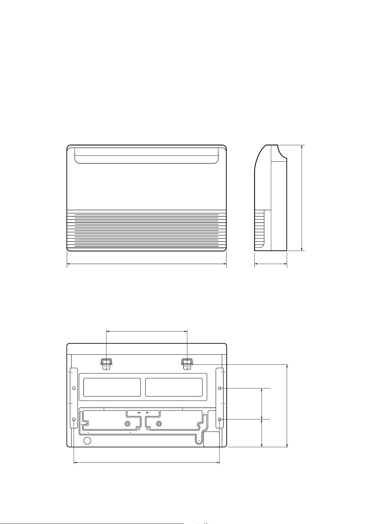
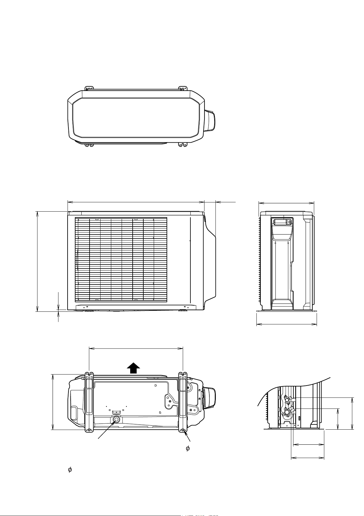
OUTLINE AND DIMENSIONS
INDOOR UNIT
Unit : mm
655
(rear view)
990
500
199
200175
530
900
2006.10.16 2
Page 4
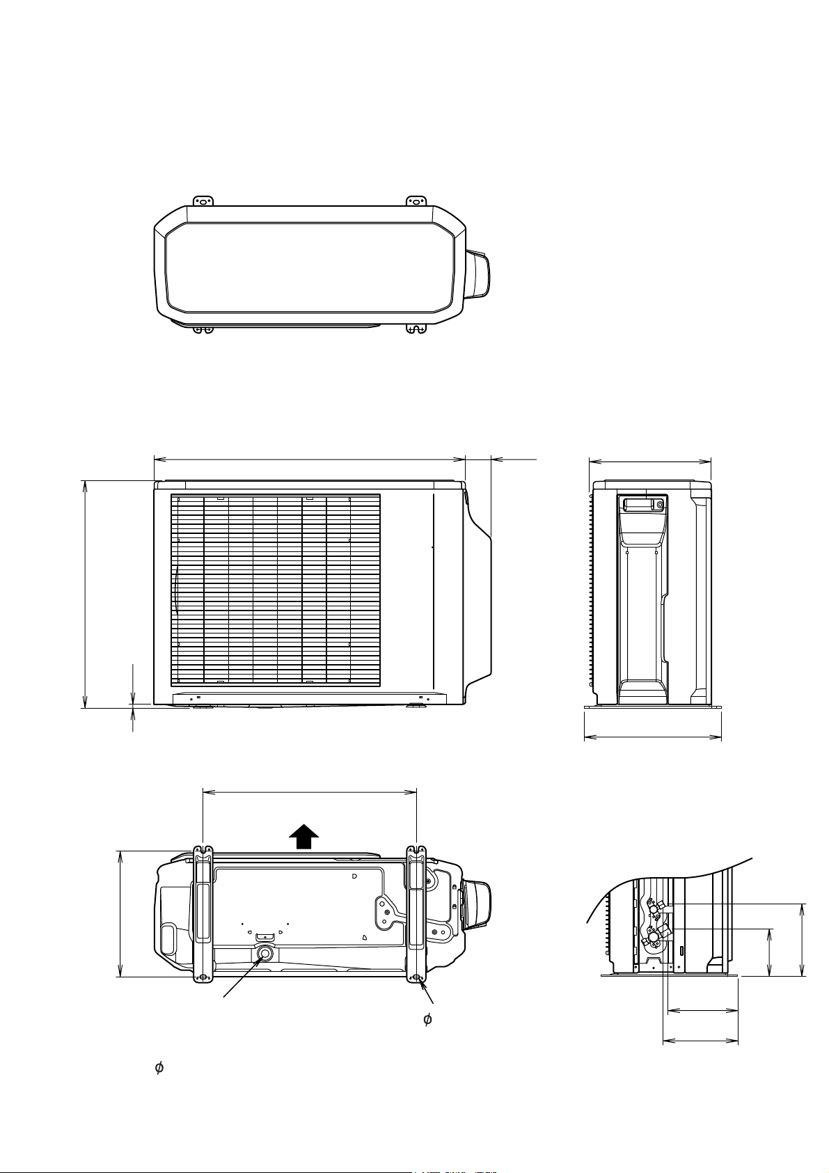
OUTDOOR UNIT
AOHA18LACL
Unit : mm
Top view
30066790
578
10
347
Front view
Side view
540
Air flow
320
184
121
Drain pipe
Bottom view
4- 10mm hole
mounting place
( 20)
2006.10.26 3
177
189
Page 5
OUTDOOR UNIT
AOHA24LACL
Unit : mm
Top view
31566790
578
10
347
Front view
Side view
540
Air flow
320
184
121
Drain pipe
Bottom view
4- 10mm hole
mounting place
( 20)
2006.10.26 4
177
189
Page 6
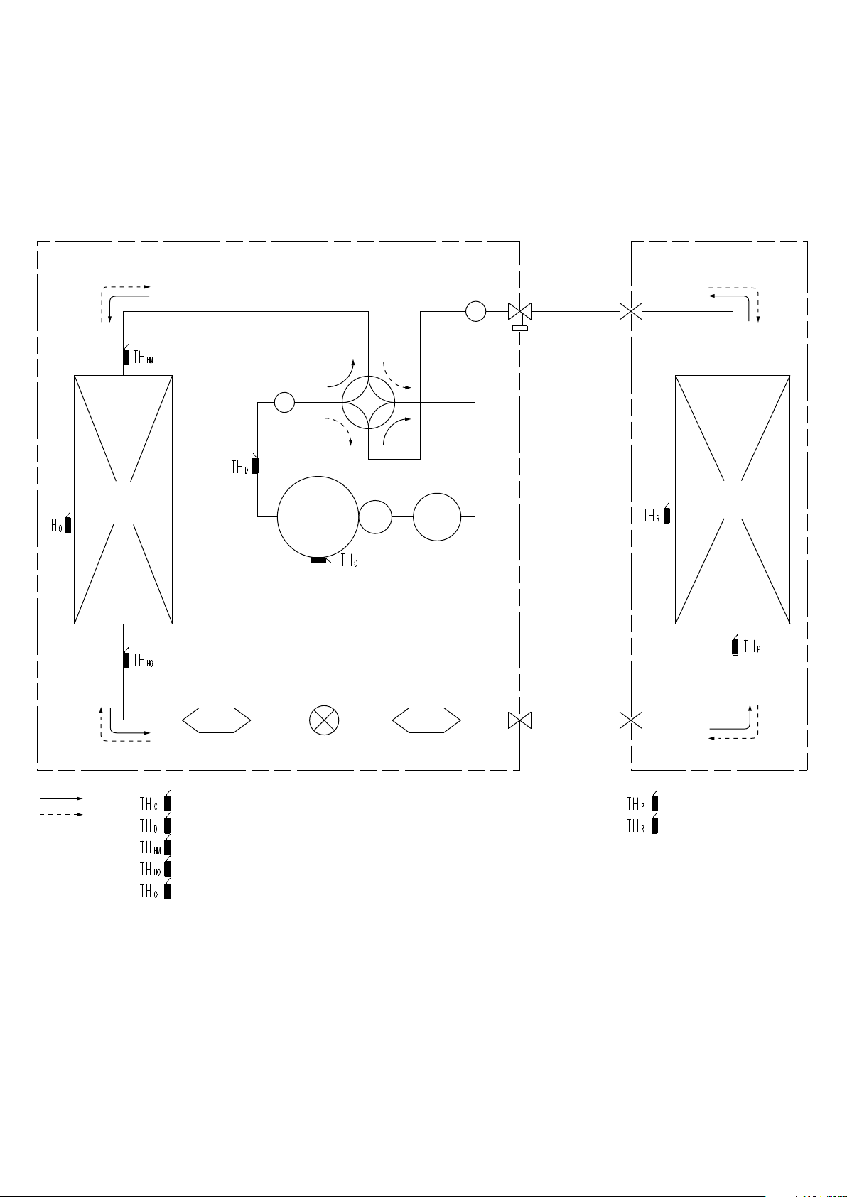
REFRIGERANT SYSTEM DIAGRAM
OUTDOOR UNIT
Heat exchanger
INDOOR UNIT
Muffler
3-Way
valve
Muffler
4-Way
valve
Heat exchanger
Accumulator
Compressor
Cool
Heat
: THERMISTOR (COMPRESSOR TEP.)
: THERMISTOR (DISCHARGE TEP.)
: THERMISTOR (HEAT EXCHANGER MED TEP.)
: THERMISTOR (HEAT EXCHANGER OUT TEP.)
: THERMISTOR (OUTDOOR TEP.)
Refrigerant pipe diameter
ABHA18LATN / AOHA18LACL
Liquid : 1/4" (6.35 mm)
Gas : 1/2" (12.70 mm)
ABHA24LATN / AOHA24LACL
Liquid : 1/4" (6.35 mm)
Gas : 5/8" (15.88 mm)
Expansion
valve
StrainerStrainer
2-Way
valve
: THERMISTOR (PIPE TEP.)
: THERMISTOR (ROOM TEP.)
2006.10.26 5
Page 7
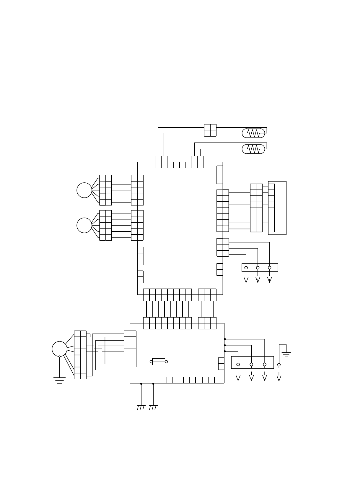
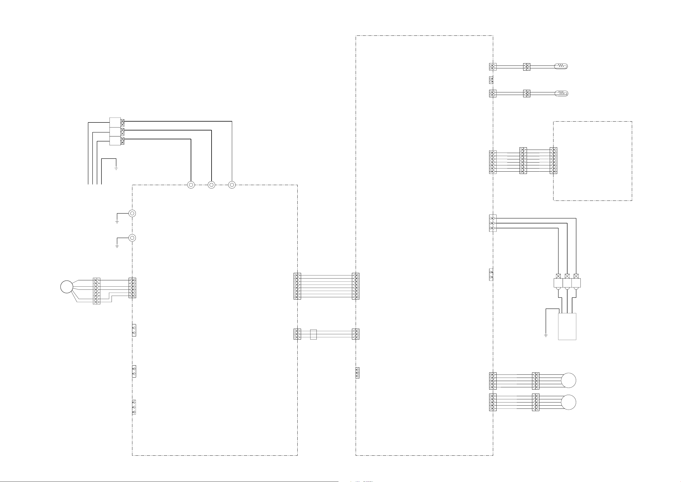
CIRCUIT DIAGRAM
INDOOR UNIT
STEP MOTOR
STEP MOTOR
M
M
1
2
3
4
5
1
2
3
4
5
BROWN
1
2
ORANGE
3
YELLOW
4
5
BROWN
1
2
ORANGE
3
YELLOW
4
5
RED
WHITE
RED
WHITE
1
1
CN5 CN7
1
1
2
2
3
3
CN12
4
4
5
5
CONTROLLER
1
1
2
2
3
3
4
4
5
5
1
2
3
1
2
PCB ASSY
( MAIN PCB )
CN11
CN9
CN10
123 4 5 6 7 8
123 4 5 6 7 8
BLACK
BLACK
2
2
1
2
1
1 2
1 1
2
2
CN8
CN4 CN1
123
123
2
GRAY
GRAY
BLACK
BLACK
PIPE TEMP.
THERMISTOR
ROOM TEMP.
THERMISTOR
1
2
CN3
3
RED
1
1
ORANGE
2
2
YELLOW
3
3
WHITE
4
4
BLUE
CN13CN14
5
5
PURPLE
6
6
GRAY
7
7
RED
1
1
WHITE
2
2
BLACK
3
3
1
2
3
4
5
6
7
8
1
1
2
2
3
3
4
4
5
5
6
6
7
7
8
8
TERMINAL
1
2
CN6
1 2 3
TO REMOTE CONTROL UNIT
( OPTION )
INDICATOR PCB ASSY
FAN MOTOR
F M
GREEN /
YELLOW
GRAY
GRAY
GRAY
GRAY
GRAY
GRAY
GRAY
GRAY
123 4 5 6 7 8
123 4 5 6 7 8
1
1
2
2
3
3
4
4
5
5
6
6
7
7
8
8
BROWN
YELLOW
WHITE
BLACK
RED
1
2
3
4
5
6
1
2
3
4
5
6
E101
CN104
POWER SUPPLY
PCB ASSY
CN105
E102
FUSE 3.15A
CN102 CN103
123
250V
2
1
GRAY
GRAY
123
123
CN101
W105
W102
W101
CN108
1 2
GRAY
RED
WHITE
BLACK
1
2
CN106
1 2
TERMINAL
3
TO OUTDOOR UNIT
GREEN
GREEN
2006.10.17 6
Page 8
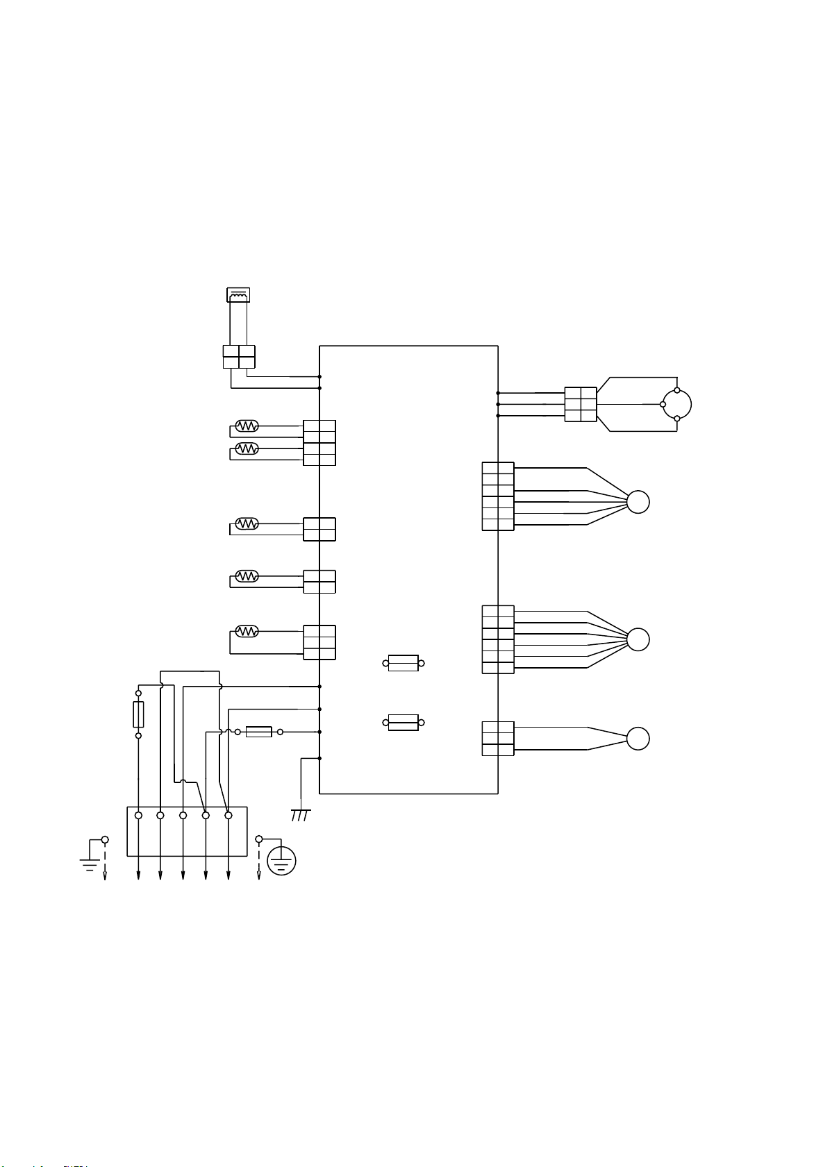
OUTDOOR UNIT
PIPE TEMPERATURE
THERMISTOR
DISCHARGE PIPE
TEMPERATURE THERMISTOR
COMPRESSOR
TEMPERATURE THERMISTOR
PIPE ( MID )
TEMPERATURE THERMISTOR
OUTDOOR TEMPERATURE
THERMISTOR
WHITE
FUSE 250V 5A
BLACK
BLACK
REACTOR
YELLOW
YELLOW
12
2
1
FUSE 250V 20A
BLACK
RED
WHITE
BLACK
BLACK
BROWN
BROWN
BROWN
BROWN
BLACK
BLACK
BLACK
BLACK
WHITE
BLACK
W10
W11
1
1
2
2
CN71
3
3
4
4
121
CN73
2
CONTROLLER PCB ASSY
CN72
CN70
( MAIN PCB )
FUSE
15A 250V
FUSE
3.15A
250V
RED
GREEN
121
1
2
3
2
1
2
3
W4
W2
W1
W3
S (S)
F M
FAN MOTOR
EXPANSION
PMV
VALVE
4WV
VALVE
R (R)
C M
RED
RED
W7
WHITE
W8
BLACK
W9
RED
1
1
2
2
BLACK
3
3
CN801
CN40
CN30 4-WAY
WHITE
4
4
YELLOW
5
5
BLUE
6
6
RED
1
1
BROWN
2
2
BLUE
3
3
ORANGE
4
4
YELLOW
5
5
WHITE
6
6
BLACK
1
1
2
2
BLACK
3
3
1
1
2
3
WHITE
2
3
BLACK
COMPRESSOR
C (T)
TERMINAL
2
1 3 L
N
( N )
TO INDOOR UNIT
POWER SOURCE
2006.11.14 7
Page 9
INDOOR PCB CIRCUIT DIAGRAM
CONTROL UNIT
ABHA18LATN : EZ-00607HSE
ABHA24LATN : EZ-00603HSE
3
2(N)
1
TERMINAL BOARD
UL1015 AWG20 BLACK
CN8
CN8-1
CN8-2
CN7-1
CN7-2
CN5-1
CN5-2
B2B-XASK-1-A
CN7
B2B-XAYK-1-A
ROOM TEMPERATURE THERMISTOR
GRAY
GRAY
PIPE TEMPERATURE THERMISTOR ( ENTRANCE )
PIPE TEMPERATURE THERMISTOR ( MID )
BLACK
BLACK
CN5
B2B-XAKK-1-A
INDICATOR PCB
CN13
B07B-PASK-1
CN13-1
CN13-2
CN13-3
CN13-4
CN13-5
CN13-6
CN13-7
UL1015 AWG20 WHITE
UL1015 AWG20 RED
RED
ORANGE
YELLOW
WHITE
BLUE
PURPLE
GRAY
1
2
3
4
5
6
7
8
CN201
S08B-PASK-2
1
2
3
4
5
6
7
8
K04E1-0600HSE-D0
CN201-1
CN201-2
CN201-3
CN201-4
CN201-5
CN201-6
CN201-7
CN201-8
DC FAN MOTOR
F M
OUTDOOR UNIT
UL1015 AWG16
UL1015 AWG16
DC FAN MOTOR
1
2
3
4
5
6
7
8
DRAIN PUMP
B2P3-VH-B-E
GREEN
GREEN
CN105
B5P6-VH-B
RED
BLACK
WHITE
YELLOW
BROWN
CN106
E101
E102
CN105-6
CN105-5
CN105-4
CN105-3
CN105-2
CN105-1
CN106-1
CN106-2
W101 W102
W105
POWER SUPPLY PCB
K06AL-0600HSE-P0
CN104-1
CN104-2
CN104-3
CN104-4
CN104-5
CN104-6
CN104-7
CN104-8
CN101-1
CN101-2
CN101-3
POWER DRIVE
CN104
B08B-PASK-1
GRAY
GRAY
GRAY
GRAY
GRAY
GRAY
GRAY
GRAY
DC SUPPLY
CN101
B03B-PASK-1
EMI FILTER
POWER DRIVE
B08B-PASK-1
DC SUPPLY
B03B-PASK-1
GRAY
GRAY
GRAY
CN4
CN1
CONTROLLER PCB ASSEMBLY
( MAIN PCB )
ABHA18LATN : K06AK-0603HSE-C1
ABHA24LATN : K06AK-0600HSE-C1
CN4-1
CN4-2
CN4-3
CN4-4
CN4-5
CN4-6
CN4-7
CN4-8
CN1-1
CN1-2
CN1-3
CN14-1
CN14-2
CN14-3
CN6-1
CN6-2
REMOTE
CN14
B3B-XAKK-1-A
RED
WHITE
BLACK
FRESH AIR
CN6
B02B-PAMK-1
TERMINAL BOARD
EARTH WIRE
REMOTE CONTROL UNIT
UL1430 AWG22 BLACK
UL1430 AWG22 WHITE
3 2 1
UL1430 AWG22 RED
EIB OUT
CN103
B2B-XH-AM
CN103-1
CN103-2
FLOAT SWITCH
B03B-XARK-1-A
EIB I N
CN102
B3B-XH-AM
CN102-1
CN102-2
CN102-3
2006.10.26 8
CN9
CN9-1
CN9-2
CN9-3
CN11-1
CN11-2
CN11-3
CN11-3
CN11-4
CN11-5
CN12-1
CN12-2
CN12-3
CN12-3
CN12-4
CN12-5
CN11
B05B-XASK-1-A
BROWN
RED
ORANGE
YELLOW
WHITE
BROWN
RED
ORANGE
YELLOW
WHITE
CN12
B05B-XARK-1-A
LOUVER
U - D
LOUVER
L - R
Page 10
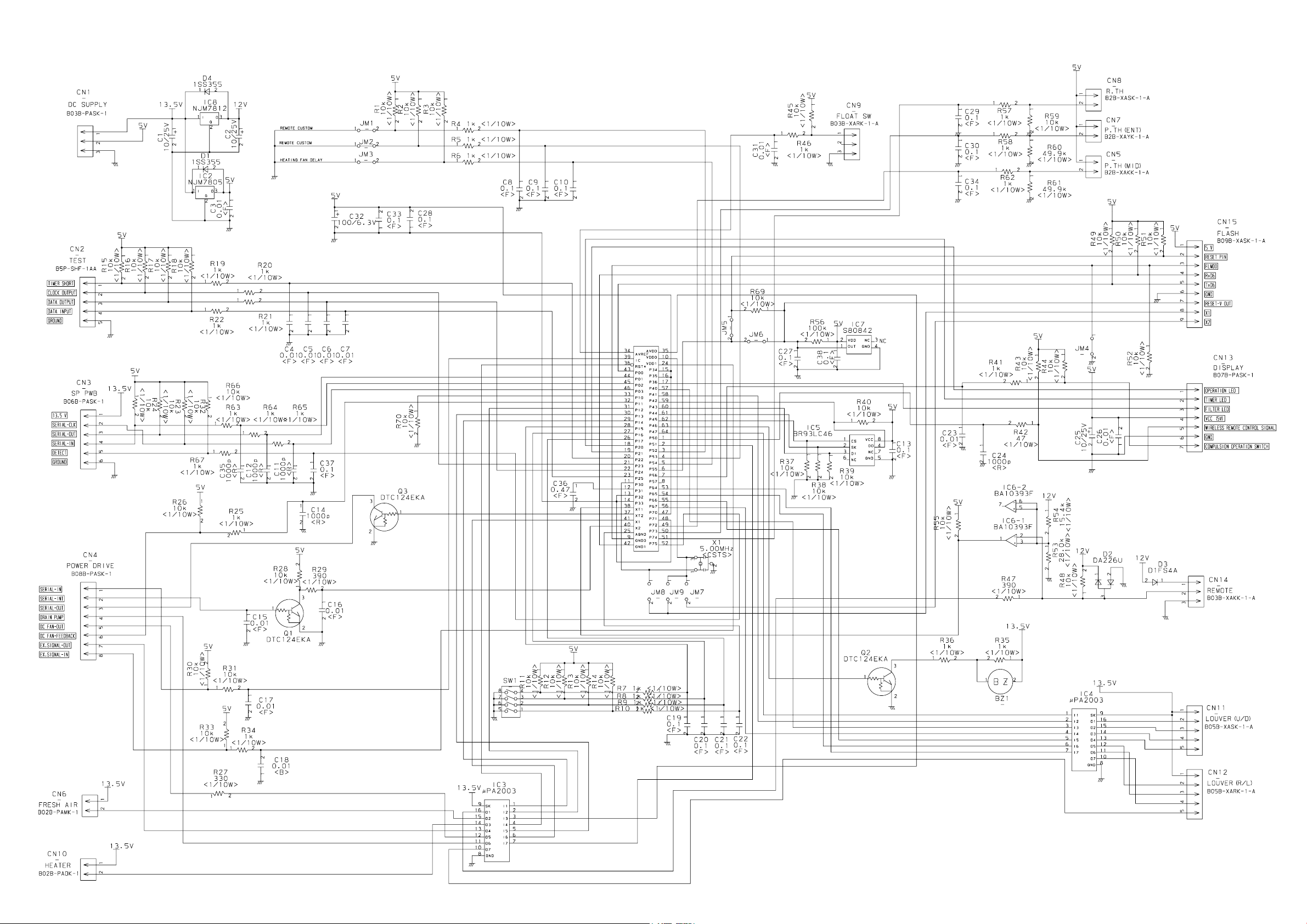
CONTROLLER PCB ASSEMBLY
ABHA18LATN : K06AK-0603HSE-C1
ABHA24LATN : K06AK-0600HSE-C1
IC1
UPD78F0535GK
(R)-012-UET-A
2006.10.26 9
Page 11

INDOOR UNIT
POWER SUPPLY PCB
K06AL-0600HSE-P0
2006.09.26 10
Page 12

OUTDOOR PCB CIRCUIT DIAGRAM
CONTROL UNIT
AOHA18LACL : EZ-0069HUE
AOHA24LACL : EZ-006AHUE
TO INDOOR UNIT
POWER SOURCE
AC220 - 240V
50Hz
SERIAL
L
N
1
2
3
4
5
TERMINAL
EMI FILTER
ATFC-25-15-12
W103
UL1015 AWG20
BLACK
W100
UL1015 AWG20
WHITE
W102
UL1015 AWG20 BLACK
W101
UL1015 AWG14
BLACK
F202
5A - 250V
F201
20A - 250V
2 TURN
DISCHARGE TEMPERATURE THERMISTOR
PIPE TEMPERATURE THERMISTOR
OUTDOOR TEMPERATURE THERMISTOR
EMI FILTER
ATFC-25-15-12
1 TURN
EARTH
UL1015 AWG14
BLACK
UL1015 AWG14
WHITE
UL1015 AWG20
UL1015 AWG16
RED
GREEN
BLACK
BLACK
BROWN
BROWN
BLACK
BLACK
B
W1
( A-1 )
B
W2
( B-1 )
B
W4
( D-1 )
B
W3
( C-1 )
1
CN71
2
B04B-PASK-1
3
WHITE
4
1
CN70
2
B03B-PASK-1
WHITE
3
REACTOR
UL3271 AWG16
WHITE
UL3271 AWG14
RED
W10 W11
B B
CONTROLLER PCB ASSEMBLY
( MAIN PCB )
AOHA18LACL : K06AX-0600HUE-C1
AOHA24LACL : K06AX-0601HUE-C1
CN30
B2P3-VH-B-C
BLACK
CN801
B5P6-VH-B-L
WHITE
W7
B
W8
B
B
W9
1
2
3
1
2
3
4
5
6
U
RED
V
WHITE
W
BLACK
UL3271 AWG16 x 3
BLACK
BLACK
RED
BLACK
WHITE
YELLOW
BROWN
EMI FILTER
RED
WHITE
BLACK
4-WAY VALVE
F M
COMPRESSOR
C M
DC FAN MOTOR
COMPRESSOR TEMPERATURE THERMISTOR
PIPE ( MID ) TEMPERATURE THERMISTOR
BROWN
BROWN
BLACK
BLACK
CN73
1
B02B-XAMK-1-A
2
GREEN
1
CN72
B02B-XH-AM
2
WHITE
2006.10.26 11
CN40
B6B-XARK-1-A
RED
1
2
3
4
5
6
RED
BROWN
BLUE
ORANGE
YELLOW
WHITE
EXPANSION VALVE MOTOR
M
Page 13

CONTROLLER PCB ASSEMBLY
AOHA18LACL : K06AX-0600HUE-C1
AOHA24LACL : K06AX-0601HUE-C1
POWER SOURCE
AC230V
50Hz
1 2
4 3
L1
10 - 60
16 - 75
H Y I C 1
HU2001
R119
10K
1%
R134
R133
10K
10K
1%
2
3
502
1.0K
C503
0.1
<F>
-
1
+
I C104-1
BA2902F
13
-
12
+
I C104-4
BA2902F
5V
C561
0.01
<F>
1%
14
R503
10K
R561
1.0K
12V
I C40
TD62064
2
7
9
16
GND1
4
5
12
13
C11
0.1
<F>
3
2
6
-
5
+
I C10-2
BA2903F
12V
R135
10K
1%
R141
10K
1%
500
1.0K
I C500
MB90460
17
P63
VCC
56
AVCC
11
P62
16
2
P00
25
P46
35
3
59
58
60
21
34
47
27
5V
15V
+
1
-
7
I C80
uLN2003
1C
1B
1
2C
2
2B
3
3B
3C
4C
4
4B
5
5B
5C
6B
6
6C
7B
7
7C
8B
9
8
COM
E
C500
0.1
<F>
12V
16
15
14
13
12
11
10
28
29
30
31
32
33
57
41
42
43
44
10
9
8
7
5
6
4
22
23
1
3
2
P12
P01
P17
P50
P13
P37
P36
P14
P40
P15
P16
MD2
P11
AVR
P26
P24
P02
P25
P03
P30
P04
P31
P05
P32
P06
P33
P07
P34
P10
P35
P60
C
P20
P61
P21
MD0
P22
MD1
P23
P44
P57
P43
P42
P56
P55
P41
P54
P45
RSTX
P52
P53
P27
AGND
P51
X0
GND
X1
GND
X500
8.00MHz
<CSTS>
26
40
36
37
38
39
12
45
46
50
51
52
53
54
55
14
15
18
20
64
63
62
61
1
19
48
13
24
49
C502
+
0.1
<F>
C501
10/25V
2006.10.26 12
R164
22K
C111
4700P
<B>
C125
0.1
<F>
15V
-12V
R560
100K
+
-
5V-2
R116
15K
1%
R117
22K
1%
C115
0.1
<F>
C116
0.1
<F>
5V
5V
C135
1000P
<B>
R168
22K
R170
RESET
2
VDD
1
OUTNCGND
I C560
S80842
R115
22K
1%
5
+
4
I C102-1
BA2901F
R165
22K
68K
+
-
5V-2
2
C131
3
4
<F>
R112
10K
1%
C110
0.1
R581
10K
14
I C102-3
BA2901F
0.1
<F>
15V
C112
0.1
<F>
5V
C128
0.1
<F>
R169
22K
C133
C132
+
2.2/
2.2/
50V
50V
R582
10K
R585
1.0K
R93, R92, R91, R90
15V
+
-
+
R583
1.0K
10K x 4
9
8
C134
0.1
<F>
D112
DAN217U
5V
R584
22K
BR93LC46
CS1
2
SK
3
D I
6
NC
5V
C580
0.1
<F>
I C570
VCC
DO
NC
GND
R570
10K
AOYA18LACL
AOYA24LACL
D113
DAN217U
5V
5V
8
4
7
5
JM101
JM102
JM103
JM100
JM101
JM102
JM103
JM100
C570
0.1
<F>
DCV
TEST
DCV-F
UDZS8.2B
BLm31
<A601>
BLm31
<A601>
DCV
DAN217U
D50
1SS355
D51
L50
L51
D52
1SS355
R51
C50
35V
D305
47
47/
15V
<1/8W>
<1/8W>
<1/8W>
<1/8W>
+
5V
Q300
DTC114EUA
DCV-F
R52
470K
1%
R53
510K
1%
R54
510K
1%
R55
510K
1%
C51
1.0
<B>
R56
150K
<2W>
5V
C300
100P
<CH>
2200P
UF4005
I C50
TOP243P
1
M
2
S
3
S
4
C
1
<1/16W>
<1/10W>
C52
<E>
R57
0R0
D53
S
S
D
-
+
R83
27K
8
7
5
2
3
R81
1.0K
5V 5V
5V
7
I C302-2
BA2903F
RPZ-1F
1
2
3
4
5
JM1
T60
15V
L300
ELC0507RA
U
V W
W7W8W9
I C200
FSBS20CH60
C214
2200P
<B>
IPM-G
15V
IPM-G
C305
0.1
<F>
DAN217U
3 3
C64
+
330/
25V
D63
1SS355
I
+
D303
21
C69
100/
25V
-12V
1
OG123
2
-
1
3
+
-
+
C85
10/
25V
6
-
5
+
10
+
5
7
-
6
C330
1000P
<B>
15V
D304
DAN217U
C86
<B>
330P
D60
D1FL20U
D61
D1FL20U
C66
100/
25V
D64
1SS355
C87
<B>
BA7805
+
2
I C60
+
470P
C84
0.1
<F>
9
8
7
6
D62
D1FL20U
1
2
3
4
5
6
7
8
9
10
11
12
13
14
15
16
17
18
19
20
C306
0.1
<F>
R309
5.76K
1%
R310
143
1%
VCC
COM
I N
I N
I N
VFO
CFOD
CSC
I N
VCC
VB
VS
I N
VCC
VB
VS
I N
VCC
VB
VS
+
R210
1.0K
C65
470/
25V
21
NU
22
NV
23
NW
U V W
24
U
25
V
26
W
27
P
DCV
R211
R212
R213
R214
R215
C218
0.1
<HCP>
R216
R217
0.15
<1W>
1%
x 7
R307 195K
<RN-1/2W>
R308 195K
<RN-1/2W>
R311
8.66K
1%
15V
12V
R61
5V
1.0K
C67
0.1
<F>
C68
+
100/
25V
-12V
Page 14

ERROR CONTENTS
INDOOR UNIT
Troubleshooting with the indoor display
Troubleshooting at the display is possible either on the
wired or wireless remote control.
OPERATION lamp (Red)
TIMER lamp (Green)
FILTER lamp (Orange)
The OPERATION, TIMER and FILTER lamp operate as follows table
according to the error contents.
Error contents
Indoor signal error
Wired remote controller abnormal
Indoor room temperature sensor error
Indoor heat exchanger temperature
sensor (middle) error
Indoor heat exchanger temperature
sensor (inlet) error
Float switch operated
Outdoor discharge pipe temperature
sensor error
Outdoor heat exchanger temperature
sensor (outlet) error
Outdoor temperature sensor error
Compressor temperature sensor error
2-way valve temperature sensor error
3-way valve temperature sensor error
Outdoor heat exchanger temperature
sensor (middle) error
Indoor manual auto switch abnormal
Power supply frequency detection error
IPM protection
CT error
Compressor location error
Outdoor fan error
Connected indoor unit abnormal
Outdoor unit computer communication
error
Indoor fan abnormal
Discharge temperature error
Exessive high pressure protection on
cooling
4-way valve abnormal
Pressure switch abnormal
Compressor temperature error
Active filter abnormal
PFC circuit error
: 0.5s ON/0.5s OFF (Flash)
: OFF
OPERATION
lamp (Red)
(2 times)
(2 times)
(2 times)
(2 times)
(3 times)
(3 times)
(3 times)
(3 times)
(3 times)
(3 times)
(3 times)
(4 times)
(4 times)
(5 times)
(5 times)
(5 times)
(5 times)
(5 times)
(5 times)
(6 times)
(7 times)
(7 times)
(7 times)
(7 times)
(7 times)
(8 times)
(8 times)
TIMER lamp
(Green)
(8 times)
(2 times)
(3 times)
(4 times)
(6 times)
(2 times)
(3 times)
(4 times)
(8 times)
(2 times)
(4 times)
(2 times)
(3 times)
(5 times)
(6 times)
(7 times)
(8 times)
(2 or 3 times)
(2 times)
(3 times)
(4 times)
(5 times)
(6 times)
(2 or 3 times)
(4 times)
FILTER lamp
(Orange)
(2 times)
(3 times)
(4 times)
Troubleshooting at the remote control LCD
This is possible only on the wired remote control.
[ SELF-DIAGNOSIS ]
If an error occurs, the following display will be shown.
("EE" will appear in the set room temperature display.)
Unit number
Error code
SUMOTUWETH FR
Error code Error contents
01
13
26
Indoor signal error
27
00
02
04
28
09
0C
06
0A
15
1d
1E
29
20
2A
17
18
1A
1b
1F
1c
12
0F
24
2c
16
2b
19
25
Wired remote controller abnormal
Indoor room temperature sensor error
Indoor heat exchanger temperature sensor (middle) error
Indoor heat exchanger temperature sensor (inlet) error
Float switch operated
Outdoor discharge pipe temperature sensor error
Outdoor heat exchanger temperature sensor (outlet) error
Outdoor temperature sensor error
Compressor temperature sensor error
2-way valve temperature sensor error
3-way valve temperature sensor error
Outdoor heat exchanger temperature sensor (middle) error
Indoor manual auto switch abnormal
Power supply frequency detection error
IPM protection
CT error
Compressor location error
Outdoor fan error
Connected indoor unit abnormal
Outdoor unit computer communication error
Indoor fan abnormal
Discharge temperature error
Exessive high pressure protection on cooling
4-way valve abnormal
Pressure switch abnormal
Compressor temperature error
Active filter abnormal
PFC circuit error
If "CO" appears in the unit number display, there is a remote controller
error. Refer to the installation instruction sheet included with the remote
controller.
SA
Ex. Self-diagnosis
2006.10.16 13
Page 15

Outdoor unit
Error contents
Thermistor malfunction
Abnormal discharge temperature
Current surge protection
CT abnormality
Compressor position detection malfunction
Fan malfunction
PAM voltage abnormality
Timer short
Compressor temperature protection (permanent stop)
PFC surge protection (permanent stop)
LED
on 0.1 sec / off 0.1 sec
on
on 0.5 sec / off 0.5 sec
on 2.0 sec / off 2.0 sec
on 0.1 sec / off 2.0 sec
on 5.0 sec / off 5.0 sec
on 5.0 sec / off 0.1 sec
on 1.0 sec / off 0.1 sec
on 2.0 sec / off 5.0 sec
on 5.0 sec / off 2.0 sec
2006.10.16 14
Page 16

DISASSEMBLY ILLUSTRATION
INDOOR UNIT
179
170
173
5
174
2006.09.25 15
170
178
Page 17

INDOOR UNIT
BASE ASSY
2
3
2
2
2
2006.09.26 16
1
Page 18

INDOOR UNIT
DRAIN PAN ASSY
EVAPORATOR
41
81
80
180
150
82
118
185
184
150
40
2006.09.25 17
Page 19

INDOOR UNIT
FAN MOTOR
58
56
57
67
72
71
58
72
64
67
56
70
2006.09.26 18
57
Page 20

INDOOR UNIT
PANEL
17
7
16
15
2006.09.26 19
Page 21

INDOOR UNIT
GRILLE
12
13
12
11
8
9
2006.09.26 20
8
Page 22

INDOOR UNIT
ABHA18LATN
EVAPORATOR ASSY
23
22
21
20
2006.10.26 21
Page 23

INDOOR UNIT
ABHA24LATN
EVAPORATOR ASSY
23
22
21
20
2006.10.26 22
Page 24

INDOOR UNIT
CONTROL UNIT
31
32
33
30
35
34
2006.09.26 23
Page 25

INDOOR UNIT
KIT (FLAP BASE)
10
101
105
106
101
105
107
100
102
2006.09.26 24
104
103
Page 26

INDOOR UNIT
FLAP BASE SUB ASSY
140
141
130
131
142
144
133
132
143
121
110
120
123
123
2006.09.26 25
Page 27

OUTDOOR UNIT
9
14
38
37
5
22
13
19
41
20
35
40
11
32
37
10
15
3
36
21
39
1
18
2
34
16
17
2006.10.25 26
6
7
4
Page 28

OUTDOOR UNIT
26
30
42
29
28
27
2006.10.16 27
Page 29

PARTS LIST
INDOOR UNIT
Ref.
Description
No.
1 Base Assy 9359061038 9359061038
2 Cap 9358563007 9358563007
3 Base Bracket 9358586006 9358586006
5 Top Cover 9358534014 9358534014
7 Panel 9358531112 9358531112
8 Air Filter 9358567029 9358567029
9 Grill-G 9358533017 9358533017
10 Kit (Flap Base) 9372670019 9372670019
11 Arm Bracket 9359281009 9359281009
12 Grille Support 9358602003 9358602003
13 Filter Bracket 9358607008 9358607008
15 Indicator PCB Assy 9705798038 9705798038
16 Insulation (Panel) A 9358574003 9358574003
17 Insulation (Panel) B 9358914007 9358914007
20 Evaporator Assy 9362513043 9362513050
21 Bypass PP Assy 9377819017 9377821010
2223Distributor Assy 9371325354 9371325361
Coupring Pipe Assy 9373038399
30 Control Box 9358600016 9358600016
31 Control Box Cover 9359097006 9359097006
ABHA18LATN
9373038382
Part No.
ABHA24LATN
Ord.
Q'ty
Ref.
Description
No.
100 Flap Base 9358537015 9358537015
101 Protect Cover 9358564004 9358564004
102 Support Stay 9358599006 9358599006
103 Louver 9358561010 9358561010
104 Bushing B 9358554005 9358554005
105 Louver Stopper 9358555002 9358555002
106 Louver Rod 9358559000 9358559000
107 Motor Rod 9358560006 9358560006
110 Bushing C 9358553008 9358553008
118 Kit (Insulation Flap Base) 9372672013 9372672013
120 Flap (Upper)-F 9358539019 9358539019
121 Kit (Flap Lower) 9372671016 9372671016
123 Bushing 9357942001 9357942001
130 Step Motor H 9900297015 9900297015
131 Louver Link 9358556009 9358556009
132 Louver Shaft 9358557006 9358557006
133 Louver Link Cover 9358558003 9358558003
140 Step Motor-V 9900362010 9900362010
141 Motor Base 9358562000 9358562000
142 Motor Rod-A (Step V) 9358550007 9358550007
ABHA18LATN
Part No.
ABHA24LATN
Ord.
Q'ty
32 Controller PCB Assy 97073930199707393040
9707398014 970739801433 Power Supply PCB Assy
34 Terminal 3P
35 Terminal 3P 9703345012 9703345012
40 Kit (Separate Wall A) 9372666012 9372666012
41 Kit (Separate Wall B) 9373448013 9373448013
56 Sirocco Fan Assy 9385258006 9385258006
57 Casing 9358543009 9358543009
58 Casing Cover 9358544006 9358544006
64 Fan Motor Assy 96024010179602401017
67 Rubber 9385102002 9385102002
70 Motor Fixing Table Assy 9358591000 9358591000
71 Protector 9359282006 9359282006
72 Motor Fixture 9358594001 9358594001
80 Drain Pan Assy 9372669013 9372669013
81 Drain Cap 9358746004 9358746004
82 Drain Hose Assy 9359242000 9359242000
9306489045 9306489045
143 Flap Link-Upper (Step V) 9358551004 9358551004
144 Flap Link-Lower (Step V) 9358552001 9358552001
150 Kit (Dew Proof Plate) 9372673010 9372673010
170 Arm 9358565001 9358565001
173 Hanger Bracket L 9358596005 9358596005
174 Hanger Bracket R 9358595008 9358595008
178 Cosmetic Panel R 9358535011 9358535011
179 Cosmetic Panel L 9358536018 9358536018
180 Catch 9359096009 9359096009
184 Thermistor Spring A 313728262708 313728262708
185 Pipe Thermistor Assy 9900022020 9900022020
--- Cord Bushing KR-51 9359240006 9359240006
--- Thermistor Holder Pipe 313714262805 313714262805
--- Room Thermistor Assy 9703299087 9703299087
--- Fuse BET3.15A - 250V 0600222512 0600222512
--- Side Cover R Assy 9359069041 9359069041
--- General Badge 9357914008 9357914008
2006.10.26 28
When you order parts, please make a photocopy of this page
and fill the number of the parts in the "Order" column.
Page 30

OUTDOOR UNIT
Ref.
No.
Description
1 Top Panel Assy
2 Top Panel Seal
3 Cabinet Assy
4 Blow Down Grille
5 Cabinet Right Assy
6 Fan Ring
7 Grip
9 Protective Net
10 4-Way Valve
11 Pulse Motor Valve Assy
13 Condenser Assy
14 Thermistor Spring-A
15 Thermistor Spring
16 Propeller Fan
17 Nut
18 Motor Bracket
19 Separator Assy
20 Base Assy
21 3-Way Valve Assy
22 2-Way Valve Assy
Part No.
AOHA18LACL
9309230057
9309228016
9314809040
9308884015
9309236011
9308885012
9308880017
9315319012
9900047016
9311641018
9311382027
313728262708
9300089012
9309909014
9304902003
9308872012
9312971015
9308869081
9315159014
9313064013
AOHA24LACL
9309230057
9309228016
9314809019
9308884015
9309236028
9308885012
9308880017
9315033017
9900163013
9315310019
9315302014
313728262708
9300089012
9309909014
9304902003
9308872029
9312971015
9315296030
9315414014
9313062019
Ord.
Q'ty
26 Inverter PCB Assy
27 Fuse Holder 0501454012 0501454012
28 Fuse Holder 0501456016 0501456016
29 Fuse
30 Fuse 0600372163 0600372163
32 Expansion Valve Coil
34 Fan Motor
35 Compressor Assy
36 Emblem
Thermistor Assy37
38 Heat Exchanger Thermistor 9900403010
39 Solenoid Coil
40 Compressor Thermistor 9900156046
Reactor Assy
41
Terminal42
Outdoor Temp. Thermistor---
--- Distributor ------ 9315387011
--- Condenser Assy B ------ 9315303011
9707427011
0600382018
9900057039
9602133017
9313763039
9315211019
9900148027
9970033018
9900354015
9703874031
9900210045
9707427028
0600382018
9900057039
9602451012
9315297037
9315211019
9900148027
9900403010
9970055010
9900156046
9900354015
9703874031
9900210045
2006.11.14 29
When you order parts, please make a photocopy of this page
and fill the number of the parts in the "Order" column.
Page 31

STANDARD ACCESSORIES
The following installation parts are furnished. Use them as required.
INDOOR UNIT ACCESSORIES
Name and Shape Part No.Application
Cosmetic Panel-L
Q'ty
1
Cosmetic Panel-R
1
Tapping screw ( 4 x 10)
2
Installation template
Hanger bracket (left)
Hanger bracket- (right)
For positioning the indoor unit.
For under ceiling type.
1
For suspending the indoor unit from
1
ceiling.
1
Anchor bolt (M12)
4
Special nut
4
9358536018
9358535011
0700009037
9359107002
9358596005
9358595008
313806339400
Spring washer
Wall bracket
Tapping screw ( 4 x 20)
Coupler heat insulator (large)
Coupler heat insulator (small)
Nylon fastener
Drain hose
Insulation (drain hose)
VT wire
4
For suspending the indoor unit on
2
the wall.
For fixing the wall bracket.
6
For indoor side pipe joint.
1
(Large pipe)
For indoor side pipe joint.
(Small pipe)
1
For fixing the drain hose.
1
1
Adhesive type 70 x 230
1
For fixing the drain hose
1
L 280 mm
0700007125
9358597002
0700076107
9350716012
313209328104
312300787605
9359242000
9359225003
313806350303
OUTDOOR UNIT ACCESSORIES
Name and Shape
Drain pipe
2006.09.26 30
Q'ty
For outdoor unit drain piping work.
1
Part No.Application
9303029015
Page 32

0608G3133
 Loading...