

Page 1
SPLIT TYPE
ROOM AIR CONDITIONER
CEILING
type (50Hz)
Models
Indoor unit Outdoor unit
ABH45LBAG AOH45LJBYL
CONTENTS
SPECIFICATIONS . . . . . . . . . . . . . . . . . . . . . . . . . . . . . . 1
DIMENSIONS . . . . . . . . . . . . . . . . . . . . . . . . . . . . . . . . . . 2
REFRIGERANT SYSTEM DIAGRAM . . . . . . . . . . . . . . 4
CIRCUIT DIAGRAM . . . . . . . . . . . . . . . . . . . . . . . . . . . . 5
ERROR DISPLAY . . . . . . . . . . . . . . . . . . . . . . . . . . . . .
DISASSEMBLY ILLUSTRATION . . . . . . . . . . . . . . . . . 13
PARTS LIST . . . . . . . . . . . . . . . . . . . . . . . . . . . . . . . . . 22
STANDARD ACCESSORIES . . . . . . . . . . . . . . . . . . . . 24
11
7INDOOR PCB CIRCUIT DIAGRAM . . . . . . . . . . . . . . .
8OUTDOOR PCB CIRCUIT DIAGRAM . . . . . . . . . . . . .
Page 2
SPECIFICATIONS
TYPE
INDOOR UNIT
OUTDOOR UNIT
COOLING CAPACITY
HEATING CAPACITY
ELECTRICAL DATA
POWER SOURCE
RUNNING CURRENT
INPUT WATTS
E.E.R.
STARTING CURRENT
MOISTURE REMOVAL
(kW/kW)
COMPRESSOR
TYPE
DISCRIMINATION
REFRIGERANT R410A
(A)
(kW)
(kW)
(kW)
(V)
( /Hz)
COOLING
HEATING
COOLING
HEATING
COOLING
HEATING
(A)
( /hr)
COOLING & HEATING
ABH45LBAG
AOH45LJBYL
12.5
14.0
230
1 / 50
19.5
18.5
4.45
4.25
2.81
3.29
15
4.0
Hermetic type, 6 poles,
Induction motor, Scroll
ANB33FCMMT
3,400 g
FAN MOTOR
HIGH
FAN SPEED
(r.p.m.)
AIR FLOW
INDOOER MED
LOW
OUTDOOR
INDOOER
OURDOOR
3
(m /h)
Up Fan 850 / Down Fan750
DIMENSIONS
INDOOR UNIT H x W x D (mm)
OUTDOOR UNIT
H x W x D (mm)
240 x 1,660 x 700
1,290 x 900 x 330
WEIGHT
INDOOR UNIT GROSS / NET (kg)
OUTDOOR UNIT
MAX PIPE LENGTH
MAX PIPE HEIGHT
REMOTE CONTROLLER TYPE
GROSS / NET (kg)
61 / 48
112 / 105
WIRELESS
ADDITIONAL REFRIGERANT CHARGE (R410A)
PIPE LENGTH
FULL CHARGE
AMOUNT
ADDITIONAL CHARGE
20 m
30 m
40 m
50 m
60 m
70 m
( 66 ft )
( 99 ft )
( 132 ft )
( 164 ft )
( 197 ft )
( 230 ft )
3,400 g (119.9 oz)
3,800 g (134.0 oz)
4,200 g (148.2 oz)
4,600 g (162.3 oz)
5,000 g (176.4 oz)
5,400 g (190.5 oz)
40 g / m (0.427 oz / ft.)
1,200
1,100
950
2,000
6,600
70 m
30 m
2005.12.01 1
Page 3
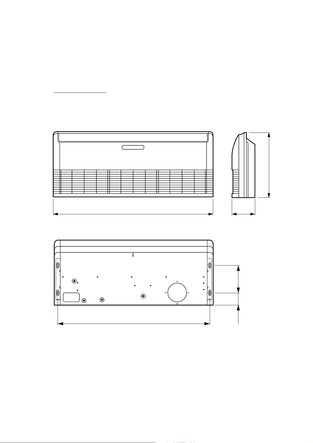
DIMENSIONS
INDOOR UNIT
Model :
(Unit : mm)
ABH45LBAG
700
1,660 240
1,600
2005.12.01 2
300
130
Page 4
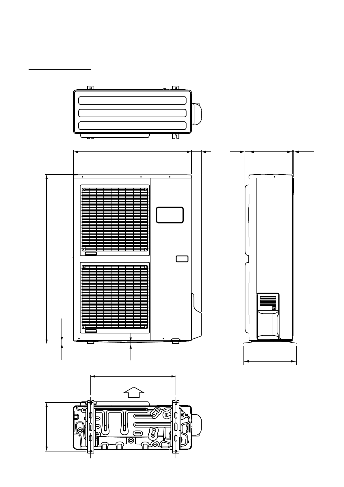
OUTDOOR UNIT
Model : AOH45LJBYL
(Unit : mm)
3177900 330 12
1290
21
9
400
650
Air Flow
370
2005.12.01 3
Page 5
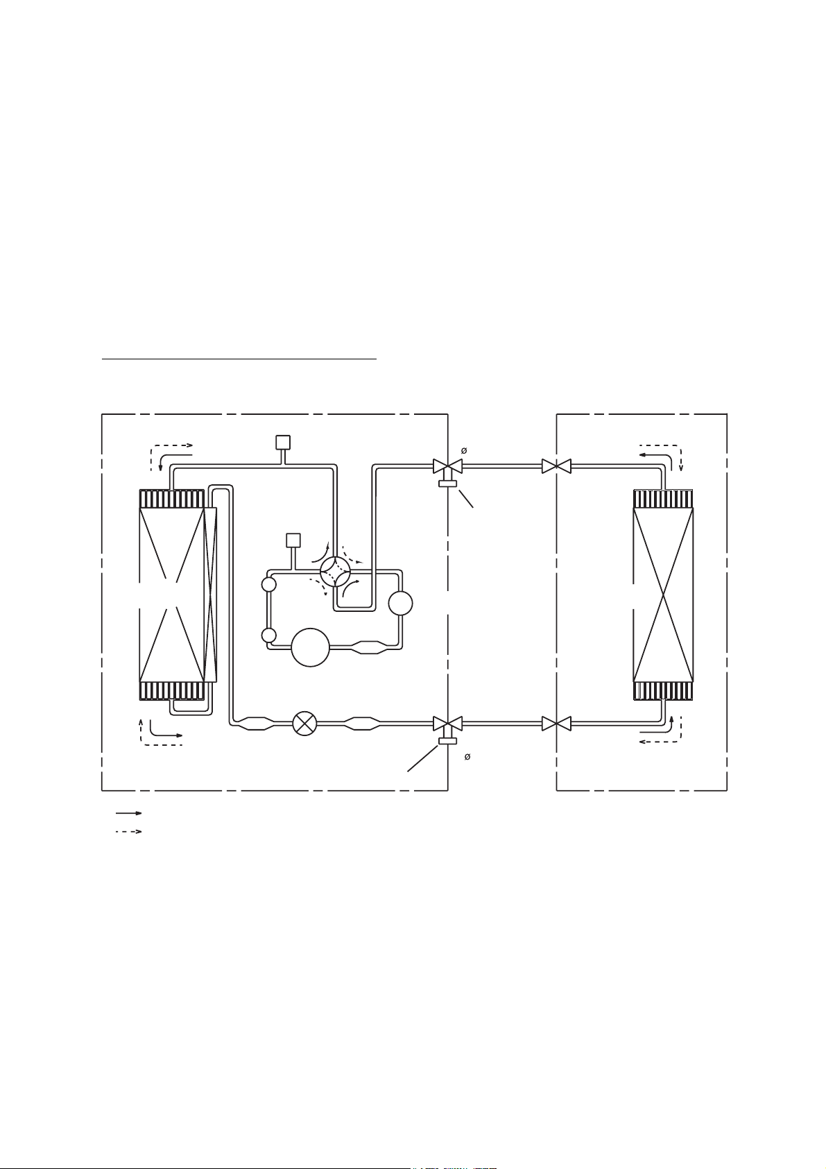
REFRIGERANT SYSTEM DIAGRAM
Model : ABH45LBAG / AOH45LJBYL
OUTDOOR UNIT
Condenser
Muffler x 2
Strainer
Pressure
Check Valve
High
Pressure
Switch
4-way
Valve
Compressor
Expansion
Valve
Strainer
Strainer
Charging Valve
Refrigerant Pipe
15.88mm (5/8")
Charging
Valve
Accumulator
Refrigerant Pipe
INDOOR UNIT
Evaporator
9.52mm (3/8")
: Cool
: Heat
2006.01.23 4
Page 6
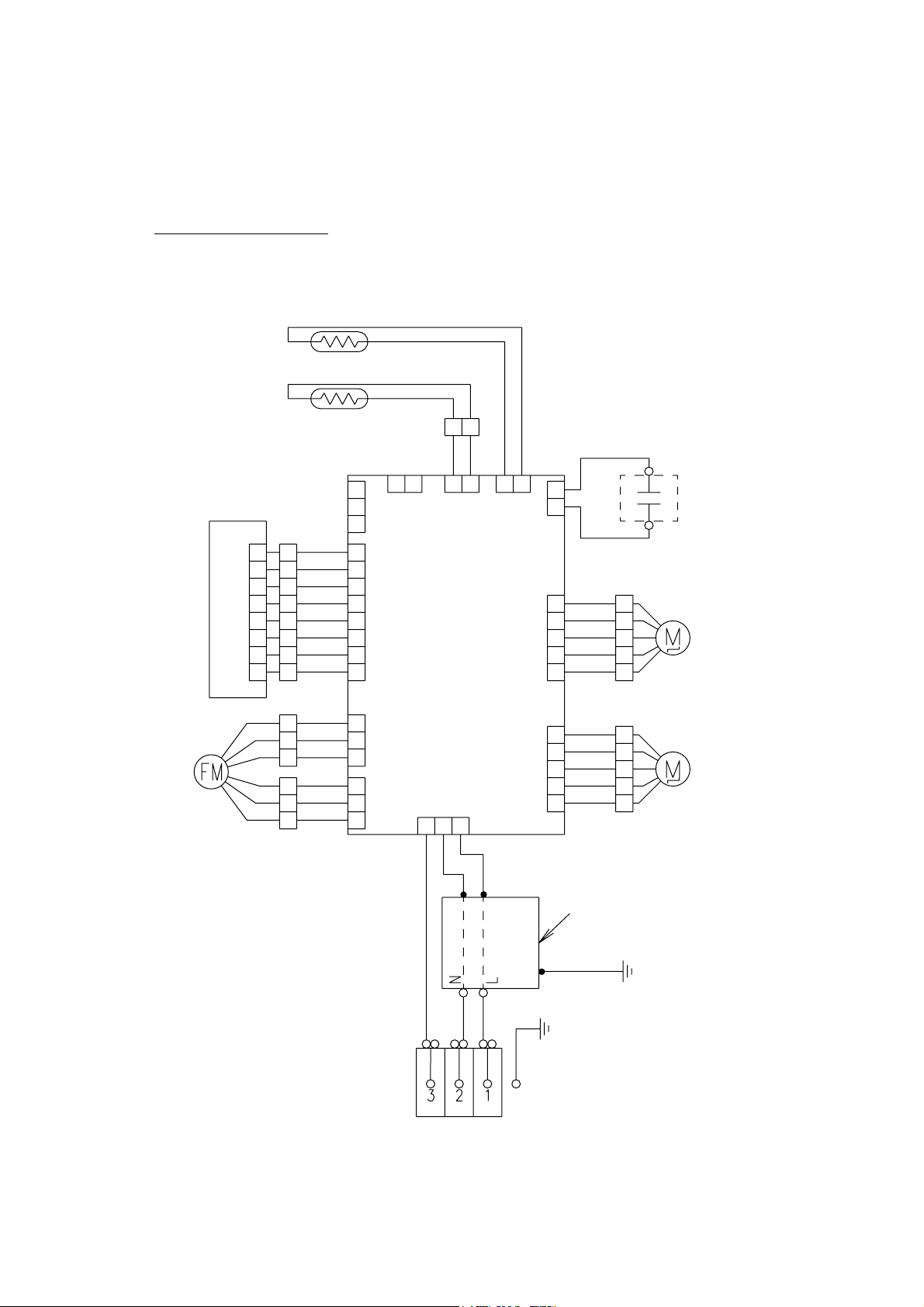
CIRCUIT DIAGRAM
Model : ABH45LBAG
Thermistor
(room temp.)
Display
board
Fan motor
CN201
Thermistor
(pipe temp.)
1
CN6
2
3
brown
red
yellow
white
blue
gray
gray
blue
black
white
red
1
2
3
4
5
6
7
8
1
2
3
1
2
CN5 CN16 CN13 CN15
1
1
2
2
3
4
5
6
7
8
3
4
5
6
7
8
1
2
orange
purple
purple
3
2
1
3
1 2
gray
gray
CN7
Control
board
CN1
233
1
white
black
black
1 21 21 2
CN8
1
CN4
2
1
2
CN10
4
5
1
2 2
CN11
4
5
black
white
white
brown
1
red
2
orange
33
yellow
4
white
5
brown
1
red
orange
33
yellow
4
white
5
Use T 3.15A - 250V
Fuse on F101
Fan motor capacitor
Step motor
(up / down)
Step motor
(left / right)
red
2005.12.01 5
Filter
board
green
white
black
Terminal
Page 7
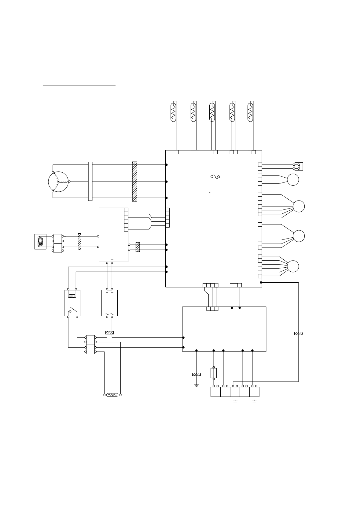
Model : AOH45LJBYL
Compressor
Choke
coil
red
U
W
Terminal
V
black
Connector
white
white
brown
EMI filter
2T
red
white
black
Active
filter
module
L1
L2
red
(pipe)
Thermistor
EMI filter
1T
brown
1
red
2
orange
3
4
5
yellow
6
P
N
yellow
blue
Thermistor
(discharge)
brown
1 2 1 2 1 2 1 2 1
U
W305
V
W304
W
W303
1
2
3
4
5
W14
W15
Printed circuit board
CN407
EMI filter
2T
white
violet
black
W107
W108
(outdoor)
Thermistor
black
Thermistor
(compressor)
blue
Fuse
F4 T 3 15A 250V
(main)
CN1 CN34
1 2 3 1 2 34
(heat sink)
Thermistor
brown
black
CN25CN26CN23CN22CN21
CN37
CN30
CN800
CN801
CN27
W200
2
1
2
1
2
3
1
2
3
4
5
6
7
1
2
3
4
5
6
7
1
2
3
4
5
6
High pressure SW
red
red
black
black
red
black
white
yellow
brown
red
black
white
yellow
brown
red
brown
blue
orange
yellow
white
4WV
Solenoid coil
FM
FM
Expansion
EV
valve coil
Fan motor 1
Fan motor 2
Relay
black
gray
Terminal
Diode bridge
gray
orange
Posistor
EMI filter
2T
orange
white
black
TM102
TM101
EMI filter
1T
Earth
brown
red
W8
black
W9
black
1
2 3
CN1
Printed circuit board
(filter)
W3
W6 W7 W1
black
green
white
Fuse
10A
2
(N)
Earth Earth
white
EMI filter
3T
W2
black
white
red
NL31
2005.12.01 6
Page 8
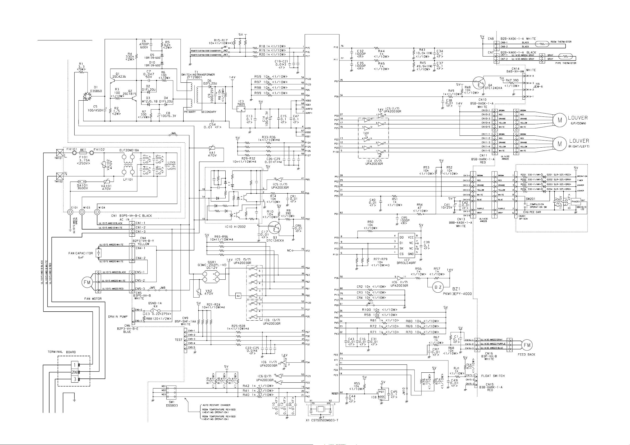
INDOOR PCB CIRCUIT DIAGRAM
Model : ABH45LBAG
POWER SOURCE
230V
50Hz
CONTROLLER PCB ASSEMBLY(MAIN PCB)
K01AL-050HHSE-C1
I C 1
uPD780058BGC
-108-8BT
POWER SUPPLY PCB
EZ-002THSE-P
INDICATOR PCB
EZ-097JHSE-D
OUTDOOR UNIT
2005.12.01 7
Page 9

OUTDOOR PCB CIRCUIT DIAGRAM
Model : AOH45LJBYL
UL1015 AWG20
POWER SOURCE
230V
50Hz
INDOOR UNIT
DC FAN MOTOR-1
DC FAN MOTOR-2
EXPANSION VALVE
F.M.
F.M.
M
4-WAY VALVE
PRESSURE SWITCH
COMPRESSOR TEMPERATURE THERMISTOR
HEAT SINK TEMPERATURE THERMISTOR
DISCHARGE TEMPERATURE THERMISTOR
PIPE TEMPERATURE THERMISTOR
OUTDOOR TEMPERATURE THERMISTOR
N
L
3
N
L
RED
BLACK
WHITE
YELLOW
BROWN
RED
BLACK
WHITE
YELLOW
BROWN
RED
BROWN
BLUE
ORANGE
YELLOW
WHITE
BLACK
BLACK
RED
RED
BROWN
BROWN
BLACK
BLACK
BROWN
BROWN
BLACK
BLACK
BLUE
BLUE
WHITE
UL1015 AWG20
BLACK
UL1015 AWG20
WHITE
UL1015
F202
AWG20
FSL 250
BLACK
10 (EM)
250V 10A
EMI FILTER
TFC-16813
1TURN
UL1015
AWG20
RED
EMI FILTER
RFC-8
3TURN
W200
SERIAL A
B
CN800
1
B7B-XASK-1-A
WHITE
2
3
4
5
6
7
CN801
B7B-XAKK-1-A
1
BLACK
2
3
4
5
6
7
CN27
1
B6B-XARK-1-A
RED
2
3
4
5
6
CN30
179844-1
1
WHITE
3
CN37
B2B-XARK-1-A
RED
1
2
CN36
B2B-XASK-1-A
1
WHITE
2
CN26
B2B-XAMK-1-A
GREEN
1
2
CN25
B2B-XAKK-1-A
1
BLACK
2
CN21
B2B-XH-AM
1
YELLOW
2
CN22
B2B-XH-AM
1
RED
2
CN23
B2B-XAEK-1-A
1
BLUE
2
UL1015
AWG20
BLACK
UL1015
AWG16
GREEN
EARTH
W1
W6
B
W2
W7
B
POWER SUPPLY PCB ASSEMBLY
K04BA-0400HUE-P0
W3
B
03 VH / SIN
1015 L250
CN1
B3B-XASK-1-A
WHITE
CT OUT
TM101
TM102
W8
W9
B
B
1
2
3
UL1015 AWG12 BLACK
UL1015 AWG12 WHITE
UL1015 AWG20 BLACK
UL1015 AWG20 WHITE
UL1007 AWG24 BLACK
UL1007 AWG24
UL1007 AWG24
INVERTER ASSEMBLY
EZ-0045HUE
R200
ZPR0YCE400A300
UL1015
AWG20
ORANGE
UL1015
AWG12
BLACK
UL1015
AWG20
VIOLET
UL1015
AWG20 WHITE
W107
WHITE
B
W108
VIOLET
B
CN34
1
B2P3-VH-B-Y
YELLOW
3
AC VOLT I N
CN1
03 XA / 1725201007 L180
1
WHITE
CT
BROWN
RED
3
4
CONTROLLER PCB ASSEMBLY
K04AW-0500HUE-C1
UL1015
AWG20
ORANGE
K201
VF12HU
-UL
UL1015
AWG12
GRAY
UL1015
AWG12
GRAY
EMI FILTER
TFC-25-15-12 2TURN
UL1015 AWG12
RED
D201
S50VB60-4000
+
-
UL1015
AWG12
BLACK
CHOKE COIL
L=0.21MH
L1
UL1015
AWG12
BROWN
L2
UL1015
AWG20
BROWN
UL1015
AWG20
WHITE
UL1015
AWG12
WHITE
+
ACTPM
( I C404 )
LACT33020B
-
EMI FILTER
TFC-25-15-12
2 TURN
P
N1
N2
I O
1
2
3
4
5
6
UL1015 AWG12 YELLOW
UL1015 AWG12 BLUE
EMI FILTER
RFC-13
2 TURN
UL1007 AWG24 BROWN
UL1007 AWG24
UL1007 AWG24
UL1007 AWG24
RED
ORANGE
YELLOW
W14
B
W15
B
CN407
06 PH / 1725201007 L480
1
ACTPM CONTROL
3
WHITE
4
5
MAIN FLASH
W305
W304
W303
CN601
B10B-PASK-1
WHITE
EMI FILTER
RFC-10
1 TURN
RED
B
WHITE WHITE
B
BLACK BLACK
UL1015
B
AWG12
1 5V
2
GND
TAUX
3
4
TTXD
5
TRXD
6
TMODE
7
TAUX3
TCK
8
/ TRES
9
10
/ TICS
2 2
3 3
1 1
RED
C. M.
COMPRESSOR
2005.12.01 8
Page 10

Model : AOH45LJBYL
CONTROLLER PCB ASSEMBLY
K04AW-0500HUE-C1
12V
B
W107
WHITE
W108
VIOLET
CN34
B2P3-VH-B-Y
YELLOW
AC VOLT I N
W200
SERIAL-A
RED
CN30
179844-1
WHITE
4-WAY VALVE
CN37
B2B-XARK-1-A
RED
PRESSUR SW1
CN26
B2B-XAMK-1-A
GREEN
COMP. TH.
CN25
B2B-XAKK-1-A
BLACK
HEART SINK
CN21
B2B-XH-AM
YELLOW
DISCHARGE TH.
CN22
B2B-XH-AM
RED
PIPE TH.
CN23
B2B-XAEK-1-A
BLUE
OUTDOOR TH.
B
PFC5000
-0502
FH2
3
1
B
CR5
RE1202
1
2
5V
1
2
R91
L202
BL02Rn1
1
2
1
2
1
2
1
2
1
2
F4
T 5A
250V
JM1
SERIAL
2.2K <1/10W>
x 2
R90
5V
L201
BL02Rn1
C162
0.1
<F>
C163
0.1
<F>
C164
0.1
<F>
C165
0.1
<F>
C166
0.1
<F>
PFC5000
-0502
FH1
K17 G5NB-1A
3
12V
1
C71 C70
R100 6.65K
<1/10W>
(1%)
R98 1.0K
<1/10W>
(1%)
R63 6.65K
<1/10W>
(1%)
R65 4.75K
<1/10W>
(1%)
R67 38.3K
<1/10W>
(1%)
VA103
470V
<TNR>
2
4WV
4
R93
R92
0.1 <F>
x 2
0.01 <F> x 2
18
1.0K <1/10W>
C73
C72
R101 10K
<1/10W>
R99 10K
<1/10W>
R62 10K
<1/10W>
R64 10K
<1/10W>
R66 10K
<1/10W>
8
x 2
PR-SW
HY I C 1
HU2001
14
7
SLR-332VR
<RED> x 4
C60
0.1
<F>
C61
0.1
<F>
C37
0.1
<F>
C38
0.1
<F>
C39
0.1
<F>
R51 4.7K
5V
<1/10W>
R52
5 4 3 2
10
5V
6
12V
12V
D28
SLR-332VR
<RED>
R43 2.2K
<1/4W>
13
4C
12
5C
11
6C
7C
10
COM
5V
8
4
7
5
C91
0.1
<F>
1
2345
1B
2B
3B
4B
5B
6B
7B
E
I C3
uLN2003A
I C201
BR93L56RF-WE2
VCC
DO
NC
GND
R206 10K
<1/10W>
1.0K
R50 10K
<1/10W>
<1/10W>
1
C51
0.022
<F>
1
2
3
4
5
6
7
89
JM157
1
CS
2
SK
D I
3
6
NC
EEPROM
THERMISTOR
R55 1.0K
<1/10W>
1
P-FM1SEL
P-V2
P-4WV-AC
P-LED
P-PR
P-SO1
P-SO
P-E2PCS1
P-E2PSK1
P-E2PDI 1
P-SWPRS1
P-SWPRS2
P-CMPTH
P-AN-HT
P-AN-TD
P-AN-TT
P-AN-TA
R56 27K
<1/10W>
3
Q51
2
2SC2412K <BQ>
FM2FDBK
SUB-CLH
P-FM2POW
P-POWER
P-AN-CT
P-FM1POW
TTXD-1
TAUX3-1
P-AFS
P-CP-POS
P-S I
P-SO
P-PR
P-LED
P-4WV-AC
P-V2
P-TRIP
P-EPV-A
P-EPV-B
P-EPV-C
P-EPV-D
P-AN-HT
P-CMPTH
P-AN-TT
P-AN-TA
P-AN-TD
JM156
C180
10K <1/10W>
x 2
SW1
6
5
4
DSS803
0.022 <F> x 2
C53
10K <1/10W> x 2
JM106
5V
R16
R17
R34
3
2
R35
1
1.0K
<1/10W>
x 2
P-S I
P-S I1
P-POWER
5V
R11
C40 0.1
<F>
0.1 <F> x 2
C78
C77
MICOM-MAIN
MICOM-SUB
MB90460
R195
17
P62
16
P46
2
35
P12
3
P50
P37
59
P36
58
P40
60
MD2
21
34
P11
47
P26
27
P02
28
P03
29
P04
30
P05
31
P06
32
P07
33
P10
57
C
41
P20
P21
42
43
P22
P23
44
10
P57
9
P56
8
P55
7
P54
5
P52
6
P53
4
P51
22
X0
23
X1
3
1
X1
8.00MHz
<EF0EC>
2
I C 1
VCCP63
AVCC
MD0
MD1
RSTX
AGND
GND
GND
56
11
25
P00
P01
26
40
P17
36
P13
37
P14
38
P15
39
P16
12
AVR
45
P24
46
P25
50
P30
51
P31
52
P32
53
P33
54
P34
55
P35
14
P60
15
P61
18
20
64
P44
63
P43
62
P42
61
P41
1
P45
19
48
P27
13
24
49
C79
0.1
<F>
0.1 <F> x 2
C19
R608 10K <1/10W>
U
X
V
Y
W
Z
R72 1.0K
<1/10W>
C17
0.01
<F>
R36 1.0K
<1/10W>
2005.12.01 9
P-AFE
P-AFDC
P-CP-POS
C18
5V
C16
4.7/50V
<PS>
5V
R158
10K
<1/10W>
SW2
KSM0632B
5V
+
C20
4.7/50V
<PS>
R126 - R128
10K <1/10W> x 3
R73 82K
<1/10W>
+
2
SUBNCVCC
1
I C6
BD4742G
C95
100P
<CH>
VOUT
GND
R113
1.0K
<1/10W>
<1/10W>
TAUX-1
P-E2PCS1
P-FM1SEL
FM1FDBK
P-E2PD I1
P-E2PSK1
P-AFDC
P-AFE
P-U
P-X
P-V
P-Y
P-W
P-Z
SUB-FWD
SUB-BKWD
TMODE-1
P-SWPRS2
P-SWPRS1
TCK-1
TRXD-1
5
4
3
YELLOW
BLUE
VILTAGE LOCK OUT
10K <1/10W> x 2
C35 - C36
0.01 <F> x 2
5V
R102
22K
3
<1/10W>
1
R114
R103 4.7K
2
27K
<1/10W>
Q91
2SC242K
<BQ>
R6R1
100K <2W> x 2
R3 100
Q1
2SC4236
<1W>
2
1
3
D10
R140 1.2
<2W>
D1
D1FL20U
P-AFS
RSTX-1
5V
B
W14
W15
B
I C400-1
5V
uPC393
R407
R403
I C400-2
uPC393
15V
I C11-1
uPC393
2
1
-
3
+
R2 1.0K
<RS - 3W>
C1
220P
<BN>
C2 0.047
<ECQB>
D2
D1FL20U
C3 <PJ>
RD5.6ES
<B2>
100/16V
R4 330 <1/4W>
R411 22K
<1/10W>
C416
1000P
<B>
TAUX-1
TTXD-1
TRXD-1
TMODE-1
TAUX3-1
TCK-1
RSTX-1
C201 - C205 500/450V x 6
R201
+
220K
<2W>
+ +++
SMOOTHING CIRCUIT
15V
C409
10/25V
<PS>
15V
+
8
2
-
1
7
15V
+
-
+
4
C412
0.1
<F>
C88
0.1
<F>
R435
3
6
5
1.0K <1/10W>
x 2
C411
C414
0.01 <F>
0.01
<F>
DAN217U x 2
D81
2
C87
330P <B>
C89
470P
COMP POSITION DETECT
<B>
SW POWER SUPPLY
T1
JPZ-200
16
15
13
12
10
9
D100
D1FL20U
+
P-U
P-V
P-W
P-X
P-Y
P-Z
P-TRIP
P-FM1POW
FM1FDBK
P-FM2POW
FM2FDBK
C7
220/
35V
ACTPM CONTROL
2
3
2
1
R437
Q401
DTC124EUA
R605
22K
<1/10W>
AA
R438
270 <1/10W>
(1%) x 2
5V
10K <1/10W> x 5
R21
R604
FLASH-MAIN
R402 3.3K
<1/4W>
D402
RD3.3ES
<B2>
R441
D82
21 1
3 3
D1FL20U x 2
1
2
3
6
7
8
15V
+
18V
1
Q403
3
DTA143
C413
0.01
<F>
A
R603
R602
R20
10K
<1/10W>
R400
R440
180K <RN - 1/2W>
<1/10W>
R406
2.94K 2.87K
<1/10W>
R401
R105
R108
2.87K
<1/10W>
(1%)
R5 10K
D8
D7
I C407 uPC24M18
D401
C406
+
D1FL
220/50V
20U
<PJ>
CN407
06 PH / 172520
1007 L480
WHITE
18V
C415
0.01
1
<F>
A
2
3
4
5
A
5V
5V
1
2
R601
3
4
5
6
7
8
9
10
C116
0.1 <HCP>
FH3
PFC5000
-0502
F2
T 3.15A
250V
FH4
x 2
PFC5000
-0502
(1%)
L100
BL02Rn1
(1%)
R104
x 2
(1%)
(1%)
R106
195K <RN - 1/2W>
(1%)
2.49K
<1/10W>
R107
C5 <PJ>
C4 <PJ>
470/25V
<1/10W>
I C8
TA7805
1
G
+ +
+
1 3
I O
G
2
ACTPM
CONTROL
TAUX
TTXD
TRXD
TMODE
TAUX3
TCK
/ TRES
/ TICS
CN601
B10B-PASK-1
WHITE
(1%) R87 2.94K
680
220/16V
2
18V
+
(1%)
<1/10W>
<1/10W>
12V
R370 - R374 <2W> x 5
R375 - R379 <2W> x 5
195K <RN - 1/2W>
x 6
R360 39
<1/2W>
U1JU44 x 3
R340
R341
R342
R343
R344
R345
5V
3I O
C6 <PJ>
100/16V
C418 <PJ>
10/35V
A
P-EPV-A
P-EPV-B
P-EPV-C
P-EPV-D
P-EPV1-A
P-EPV1-B
P-EPV1-C
P-EPV1-D
R86
R111
R89
R112
R110
R88
D301D303 D302
x 3
330K
47/35V
<PJ> x 3
<1/10W>
0.1 <F> x 3
+
C305
C323
+
C322
C304
+
R362 R363 R361
C321
C303
1.0K <1/10W> x 6
C311 - C316 1000P <B> x 6
DC FAN1
DTA143EUA
x 2
Q800
3
2
R803
10K
1
<1/10W>
C801
R804 1.0K
0.01
<1/10W>
<B>
DC FAN2
DTA143EUA
x 2
Q802
3
2
1
C804
0.01
<B>
P-AN-CT
E.E.-VALVE
JM152 - JM155
C324 - C326
0.1 <F> x 3
15V
Q801
2
15V
Q803
2
R807
10K
<1/10W>
R808 1.0K
<1/10W>
1.5K <1/10W> x 4
R97
R96
R95
R94
C332
0.1
<F>
UP
1
2
VP I
VUFB
3
4
VUFS
VP
5
6
VP I
7
VVFB
VVFS
8
9
WP
10
VP I
11
VPC
12
VWFB
VWFS
13
I PM
I C310 PS21869-A
C33
0.01
<F>
15V
1
R801 1.0K <1/2W>
3
5V5V
C800
100/
1 2
16V
3
<PJ>
D803
DAN217U
1
R805 1.0K
<1/2W>
3
D804
DAN217U
D61
DAN217U
12V
15V
C333
L300
47/
BL02Rn
35V
+
14
VN I
VNC
15
C IN
16
17
CFO
FO
18
19
UN
20
VN
C327
21
WN
0.022 <F>
P
22
23
U
24
V
25
W
26
N
5V
R40 1.0K
<1/10W>
L800
BL02Rn1
C802
0.1
<F>
+
R802
560
<1/4W>
L801
15V
BL02Rn1
R806
560 <1/4W>
5V5V
1 2
3
C803
25V1
100/16V <PJ>
C29
3
0.1
<F>
3
O1
I 1
6
O2
I 2
11
O3
I 3
16
14
O4
I 4
1
COM1
GND1
8
COM2
GND2
12
10
NC1
GND3
15
NC2
13
GND4
I C4 TD62064
R302 1.0K
<1/10W>
R33
10K
<1/10W>
C805
0.1
<F>
+
2
7
9
4
5
C328
2200P
<B>
INVERTER
1
2
3
4
5
6
7
1
2
3
4
5
6
7
5V
1
2
3
4
12V
1
2
3
4
5
6
B
W305
RED
B
W304
WHITE
W303
BLACK
B
CN800
B7B-XASK-1-A
WHITE
DC FAN MOTOR-1
CN801
B7B-XAKK-1-A
BLACK
DC FAN MOTOR-2
CN1
03 XA / 172520
1007 L180
WHITE
CT
CN27
B6B-XARK-1-A
RED
EXPANSION VALVE-A
CN50
06 XA / 172520
1007 L300
WHITE
Page 11

Model : AOH45LJBYL
POWER SUPPLY PCB ASSEMBLY
K04BA-0400HUE-P0
TM100
POWER SOURCE
230V
50Hz
TO INDOOR UNIT
EARTH
AC VOLT OUT
BLACK
WHITE
W4
W5
W6
BLACK
W7
WHITE
W3
GREEN
W8
BLACK
W9
WHITE
L1
RCH4730-021PF07
VA101
B
470V
<TNR>
VA102
470V
C101
3.3
<LE>
<TNR>
B
SA100
RA-302M
B
B
B
B
B
C104
0.033
<YE>
C105
0.033
<YE>
C106
3.3
<LE>
L2
N300300K1D7C
C107
3.3
<LE>
CT1
CT-1B
D60
5V
DAN217U
C60
220/16V
<PJ>
R60 1.0K
<1/10W>
(1%)
L4
RCH4730-021PF07
+
VR1
B2K
R61 3.74K
<1/10W>
(1%)
C111
3.3
<LE>
R68 22K
<1/10W>
C64
0.1
<F>
C65
0.1
<F>
5V
B
B
CN1
B3B-XASK-1-A
WHITE
1
2
3
TM101
TM102
CT OUT
2005.12.01 10
Page 12

ERROR CONTENTS
(Indoor unit)
Operation can be checked by lighting and flashing of the display section OPERATION,
TIMER, and VERTICAL SWING lamps. Perform judgment in accordance with the following.
VERTICAL SWING lamp (Orange)
TIMER lamp (Green)
OPERATION lamp (Red)
MANUAL
AUTO
SWING SWING TIMER
TEST RUNNING
When the air conditioner is run by pressing the remote control unit test run button,
the OPERATION, TIMER, and VERTICAL SWING lamps flash slowly at the same time.
ERROR
The OPERATION, TIMER, and VERTICAL SWING lamps operate as follows according to
the error contents.
OPERATION
OPERATION
lamp (RED)
(2 times)
(2 times)
(3 times)
(3 times)
(4 times)
(5 times)
(5 times)
(6 times)
TIMER lamp
(GREEN)
(2 times)
(3 times)
(3 times)
(4 times)
SWING lamp
(ORANGE)
Error contents
Indoor EEPROM abnormal
Outdoor EEPROM abnormal
Indoor room temperature sensor open
Indoor room temperature sensor short-circuited
Indoor heat exchanger temperature sensor open
Indoor heat exchanger temperature sensor short-circuited
Float switch operated
Indoor signal abnormal
Outdoor signal abnormal
Indoor fan abnormal
Outdoor power source connection abnormal
Outdoor heat exchanger temperature sensor open
Outdoor heat exchanger temperature sensor short-circuited
Outdoor temperature sensor open
(4 times)
(5 times)
(5 times)
(6 times)
(7 times)
: 0.1s ON/0.1s OFF (flash) : OFF
: 0.5s ON/0.5s OFF (flash)
Outdoor temperature sensor short-circuited
Outdoor discharge pipe temperature sensor or compressor
temperature sensor open
Outdoor discharge pipe temperature sensor or compressor
temperature sensor short-circuited
Outdoor high pressure abnormal
Outdoor discharge pipe temperature or compressor
temperature sensor abnormal
2005.11.30 11
Page 13

ERROR CONTENTS
(outdoor unit)
CAUTION
Always turn on the power 12 hours prior to the start of the
operation in order to ensure compressor protection
1. Make a TEST RUN in accordance with the in stallation instruction sheet for the indoor unit.
2. OUTDOOR UNIT LEDS
When a malfunction occurs in the outdoor unit, the LED on the circuit
board lights to indicate the error. Refer to the following table for the description of each error according to the LED.
LED
1 flash
2 flash
3 flash
4 flash
7 flash
8 flash
9 flash
12 flash
13 flash
14 flash
15 flash
16 flash
5 sec. ON/
1 sec. OFF
repeated
lighting
Communication error
(Indoor unit - Outdoor unit)
Discharg pipe temperature sensor
Outdoor heat exchanger temperature sensor
Outdoor temperature sensor
Compressor temperature sensor
Heat sink temperature sensor
Pressure switch abnormal
IPM error
Compressor rotor position cannot detect
Compressor cannot operate
Outdoor fan abnormal (upper fan)
Outdoor fan abnormal (lower fan)
Protect operation
No error
Error contents
SPECIAL INSTALLATION
SETTING
PUMP DOWN (Refrigerant collecting operation)
Perform the following procedures to collect the refrigerant when moving
the indoor unit or the outdoor unit.
(1) Press the push-button switch (SW2) on the circuit board once.
The LED on the circuit board starts flashing (one second ON/one second OFF). This indicates the start of PUMP DOWN operation.
When the switch is pressed while the compressor is in operation, PUMP
DOWN operation starts automatically.
When the switch is pressed while the compressor is in stop, the compressor starts to operate automatically, and then move on to PUMP
DOWN operation.
(2) PUMP DOWN operation continues for about 1 minute. When PUMP
DOWN operation is completed, the compressor stops automatically.
Then close the 2-way valve and 3-way valve immediately.
(3) Turn the power off.
PUMP DOWN SW (SW2)
2005.10.27 12
DANGER
This part (Choke coil) generates high voltages.
Never touch this part.
Page 14

DISASSEMBLY ILLUSTRATION
Model : ABH45LBAG
761
382
403
174
181
122
286
379
109
387
126
12
386
384
56
388
174
383
762
755
223
472
74
164
338-2
338-1
286
122
403
448
345-1
345-2
8
138
684
876-1
435
408
505
580
434
69
228
407
506
321
229
240-2
735
329
361
752
146
396
240-1
160
743
240
868
63
2005.12.01 13
Page 15

Model : ABH45LBAG
435
408
505
434
876-1
407
506
69
2005.12.01 14
Page 16

Model : ABH45LBAG
387
160
91
321
91
386
91
361
2005.12.01 15
Page 17

Model : ABH45LBAG
868
227
63
385
763
321
387
436
424
684
876-2
438
2005.12.01 16
Page 18

Model : ABH45LBAG
195
982-1
253-2
253-1
875
253-3
34
380
253-5
253-4
253-6
253-7
236
234
185-1
625
982-2
815-1
223
186
381-4
187
472
448
2005.12.01 17
Page 19

Model : AOH45LJBYL
4
3
2
1
6
3
2005.12.01 18
7
5
Page 20

Model : AOH45LJBYL
16
12
11
13
49
10
9
15
8
2005.12.01 19
14
Page 21

Model : AOH45LJBYL
22
20
21
23
17
18
24
19
25
42
26
2005.12.01 20
Page 22

Model : AOH45LJBYL
31
29
33
37
34
36
38
27
35
32
30
47
46
2005.12.01 21
45
44
43
28
41
40
39
48
Page 23

PARTS LIST
INDOOR UNIT
Ref.
No.
Description
Part No.
ABH45LBAG
Ord.
Q'ty
Ref.
No.
Description
Part No.
ABH45LBAG
Ord.
Q'ty
8 Air Filter 9359739005
12 Base Assy 9359680000
34 Capacitor (Fan Motor) 9900270216
56 Sirocco Fan Assy 9359701002
---- Panel Sub Assy 9360436078
63 Panel (Front) 9359734000
69 Louver 9359719007
74 Intake Grille 9359738008
91 Hinge 9359699002
109 Casing 9359704003
122 Shaft Holder-B 9357921006
126 Motor Fixing Table 9359681007
138 Kit (Separate Wall Sub Assy) 9371366012
---- Evaporator Sub Assy 9360428219
146 Evaporator Assy 9371073040
---- Drain Pan Sub Assy 9360429018
160 Kit (Drain Pan) Sub Assy 9371368016
164 Fan Motor Assy-IN 9360457004
174 Hanger Bracket 9359742005
181 Hole Cover 9359691006
185-1 Rubber Bushing 9357376004
186 Edge Cover 9361049017
187 Clamp No. 1219 313361271706
195 Clamp SKB-100 313361275805
223 Control Box Assy 9359708001
227 Badge 9359735021
228 Insulation (Louver)-R 9359721000
229 Insulation (Louver)-L 9359722007
234 Room Temperature Thermistor 9703299025
---- Pipe Temperature Thermistor 9900022020
338-1 Motor Fixture 9359702009
338-2 Motor Fixture-B 9359703006
345-1 Filter Guide-R 9359692003
345-2 Filter Guide-L 9359693000
361 Bushing 9359733003
379 Hinge Plate (Grille) 9359694007
380 Locking Spacer KGLS-6S 313209391403
381-4 Locking Spacer KGPS-6S 0600118075
382 Cover (Decoration)-R 9359744009
383 Cover (Decoration)-L 9359745006
384 Shaft 9359707004
385 Indicator PCB Assy 9702260019
386 Panel Left Assy 9359685005
387 Panel Right Assy 9359683001
388 Joint Assy 9359706007
396 Reinforcement Metal 9359697008
403 Shaft Holder Fixture 9359687009
407 Rod (Motor) 9359723004
408 Louver Link 9359726005
424 Sector Gear 9359729006
434 Louver Base 9359718000
435 Louver Spring 9359720003
436 Flap Spring 9359730002
438 Pinion 9359728009
448 Control Box-B 9359713005
472 Control Box-A 9359712008
505 Louver Stopper 9359724001
506 Louver Rod 9359725008
580 Cover (Top) 9359737001
625 Cord Bushing 9359240006
---- Thermistor Spring-A 313728262708
236 Controller PCB Assy 9705914216
240 Remote Control Unit 9371190013
240-1 Kit (Panel pipe-L) Sub Assy 9371362014
240-2 Kit (Panel pipe-R) Sub Assy 9371363011
253-1 Wire Assy (Connector) 9702321017
253-2 Wire Assy (Connector) 9702322014
253-3 Wire Assembly 9702311018
253-4 Wire Assy (Connector) 9702323011
253-5 Wire Assy (Connector) 9702319014
253-6 Wire Assy (Connector) 9702317010
253-7 Wire Assy (Connector) 9702318017
253-9 Wire Assembly 9702311018
286 Shaft Holder Bracket 9359686002
321 Flap Assy 9359731009
329 Coupling Pipe Assy 9373038214
2005.12.01 22
684 Motor Base 9359727002
735 Distributor Assy 9360455000
743 Remote Control Unit Holder 9305642014
752 Pipe Fixture Metal 9359688006
755 Kit (Cover Casing) Sub Assy 9371367019
761 Side Cover-R 9359740001
762 Side Cover-L 9359741008
763 Receiver Cover 9359714002
815-1 Terminal-3P 9900203016
868 PCB Holder 9359736004
875 Power Supply PCB Assy 9704561060
876-1 Motor, Step-H 9360479013
876-2 Motor, Step-V 9360307026
982-1 Cord Clamp-A 9359820017
982-2 Cord Clamp-B 9359821014
When you order parts, please make a photocopy of this page
and fill the number of the parts in the "Order" column.
Page 24

Outdoor unit
Ref.
No.
Description
1 Top Panel Sub Assy
2 Front Panel X
3 Fan Guard
4 Grip Side
5 Service Panel Sub Assy
6 Right Panel Sub Assy
7 Valve Cover
8 Motor Bracket Sub Assy
9 Propeller Fan Assy
10 Motor DC Brushless
11 Condenser A Assy
12 Condenser B Assy
13 Sepa Wall
14 Cap Foot
15 Base Assy
16 Inverter Assy
17 3-Way Valve Assy
18 3-Way Valve Assy
19 Compressor Assy
20 Accumulator Assy
Parts No.
AOH45LJBYL
9374417025
9374094028
9374330010
9374173013
9374415014
9374416042
9374174010
9374418046
9366378020
9601882015
9374433018
9374434015
9374135028
9374345014
9374166060
9705641068
9372205044
9372205075
9374653010
9371615011
Ord.
Q'ty
21 Solenoid
22 Pressure Switch
23 4-Way Valve
24 Check Valve Assy
25 Coil (Expansion Valve)
26 Strainer Assy
27 Inverter Box A
28 Inverter Box B
29 Inverter Box C
30 Inverter Box Duct
31 Inverter Box Cover
32 Heat Sink A
33 Act-Module
34 Relay
35 Terminal
36 Posistor
37 Inverter PCB Assy
38 Power PCB Assy
39 Clamp (Cord)
40 Terminal
41 Fuse
42 Expansion Valve
43 Thermistor (Dischage)
44
Thermistor (Heat Exchange)
45 Thermistor (Out Temp)
Compressor Temp Thermistor
46
47
Heat Sink Thermistor
48
Wire (Pressure Switch)
49
Coil, Choke 9705877016
--- Emblem-Rear 9372171011
9900165055
9900186012
9970035029
9374274017
9900190033
9372524015
9374603015
9374625017
9374605019
9374609017
9374608010
9374607013
9704258014
9900262013
9701971015
9704265012
9705642065
9705647015
9356857009
9900184025
0600376116
9900170028
9704219084
9704220066
9703516078
9373279020
9374607013
9367595051
2006.06.16 23
When you order parts, please make a photocopy of this page
and fill the number of the parts in the “Order” column.
Page 25

STANDARD ACCESSORIES
INDOOR UNIT ACCESSORIES
Name and Shape Q'ty Part No.Application
Remote
control unit
Battery
(pen light)
Remote control
unit holder
Tapping screw
( 3 x 12)
Drain hose
insulation
VT wire
Coupler heat insulator
(large)
Coupler heat insulator
(small)
Nylon fastener
Special nut A
(large flange)
1
2
1
2
1
1
2
1
Large
4
Small
4
4
Use for air conditioner operation
For remote control unit
For mounting the remote control unit
For remote control unit holder
installation
Adhesive type 70 x 230
For fixing the drain hose L 280 mm
For indoor side pipe joint
(large pipe)
For indoor side pipe joint
(small pipe)
For fixing the coupler heat insulator
For installing indoor unit
9371190013
(AR-JW1)
0600185534
9305642014
0700019098
9360464002
313806350303
9350716029
9352766015
9301501001
312300787605
313005446653
Special nut B
(small flange)
Installation
template
Auxiliary pipe
assembly
For installing indoor unit
4
For positioning the indoor unit
1
For connecting the piping
1
OUTDOOR UNIT ACCESSORIES
Name and Shape Q'ty Part No.Application
Drain pipe
Drain cap
Installation
(seal)
For outdoor unit drain piping work
(May not be supplied, depending on
1
the model)
2
For filling in a gap at the entrance of
connection cords
1
313005446759
9360022004
9374714025
9303029015
313166024302
9374756018
2005.10.27 24
Page 26

0510G2927
 Loading...