

Page 1
R410A
3 . FLOOR / CEILING TYPE :
AB 24LBAJ
D2D_AB008E/02
2006.04.21
Page 2
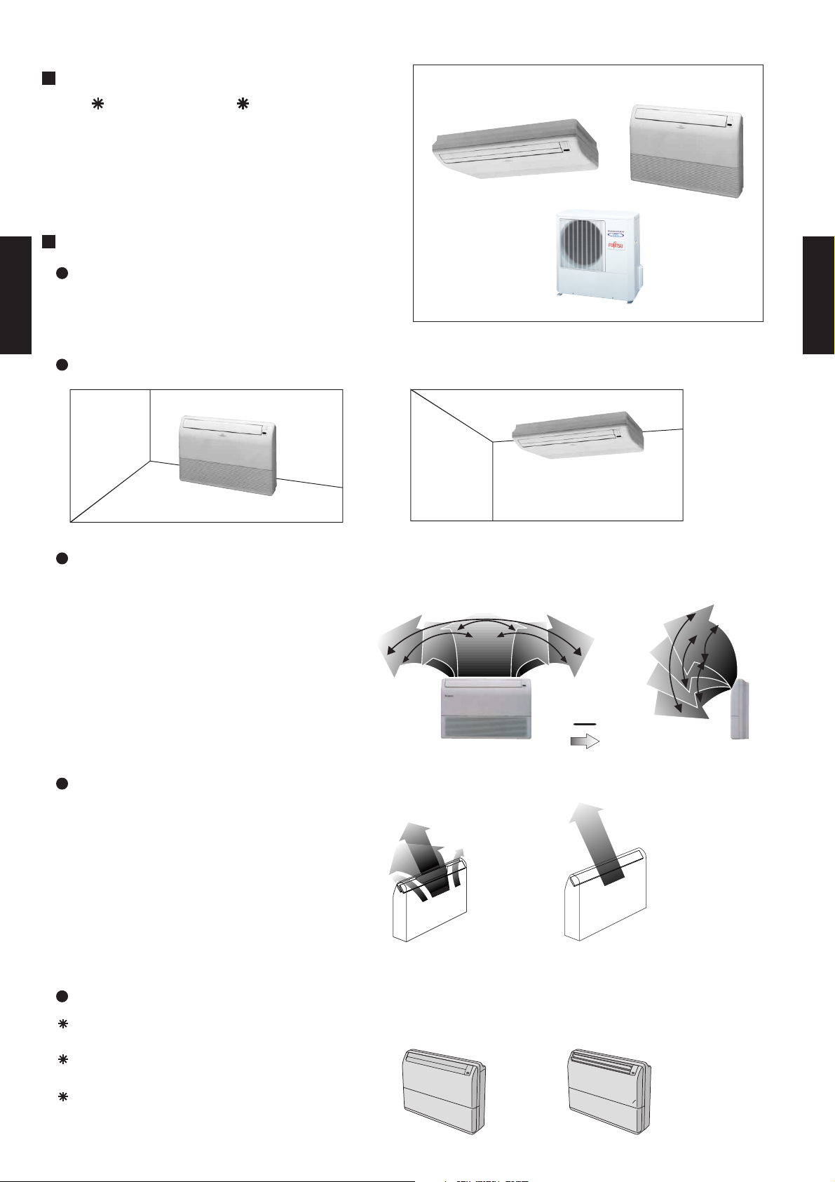
3-1. FEATURE
MODELS :
AB 24LBAJ / AO 24LMAL
FEATURES
Compact design
Symmetrical thin and compact design
Flat and round form
FLOOR / CEILING TYPE
AB24
Flexible installation
FLOOR / CEILING TYPE
AB24
FLOOR
Double auto swing
Combination of up/down and right/left air
direction swing allows three-dimensional air
direction control.
Since up/down air direction flaps operate
automatically, according to the operating
mode of the unit, it is possible to set the air
direction based on the operating mode.
Super vane
The double-flap "Super Vane" with newly
developed special configuration boosts
the air flow, sending cool air quickly to
every corner of the room.
CEILING
RIGHT and LEFT
swing
5 steps selectable
UP and DOWN
swing
Swing
Steps
7 steps selectable
Others
Auto Restart
Detachable and Washable Open Panel
Auto Shut Flaps
New model Old model
Non-operation mode Operation mode
- (03 - 01) -
Page 3
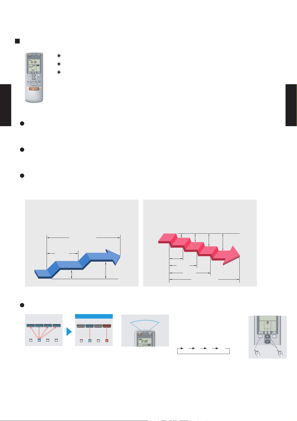
3-2. REMOTE CONTROLLER
3-2-1.
FEATURES
FLOOR / CEILING TYPE
AB24
WIRELESS REMOTE CONTROLLER
Four kinds of timer setup (ON / OFF / PROGRAM / SLEEP) are possible.
Four kinds of timers. Easy operation.
Easy to change transmission code (4 patterns) by button operation.
Built-in timers
Select from four different timer programs (On/Off/Program/Sleep).
Program timer
The program timer operates the ON and OFF timer once within a 24 hour period.
FLOOR / CEILING TYPE
AB24
Sleep timer
The sleep timer function automatically corrects the temperature thermostat setting according to
the time setting to prevent excessive cooling and heating while sleeping.
Cooling operation/dry operation
When the sleep timer is set, the set temperature
automatically rises 1 °C every hour. The set
temperature can rise up to a maximum of 2 °C.
Timer setting
60min.
1 °C
2 °C
Heating operation
When the sleep timer is set, the set temperature
automatically drops 1 °C every 30 minutes. The
set temperature can drop to a maximum of 4 °C.
1 °C
2 °C
3 °C
4 °C
30min.
60min.
90min.
Timer setting
Easy operation
After code change
Mixed-up
• Code selector switch eliminates unit
being wrongly switched.
(Up to 4 codes can be set.)
A B C D
A B
C
D
•Wide and precise
transmitting range.
1. Press the MASTER CONTROL
button for more than five seconds
to start the code change.
2. Press the (+) or (-) button to
select the desired code.
A B C D
3. Press the MASTER CONTROL
button again to end the code
change.
- (03 - 02) -
Page 4
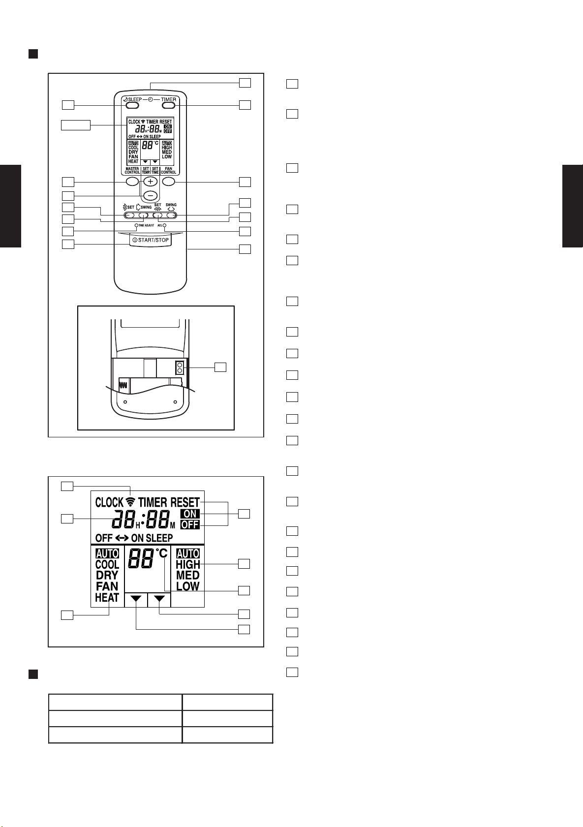
FUNCTIONS
5
1
START/STOP button
Pressed to start and stop operation
64
Display
2
Set temp./Set time buttons/Set remote controller
custom code buttons
Sets the indoor temp./Sets the current time and on-off time
/Set R.C. custom code
3
Master control button/
3
2
9
10
13
FLOOR / CEILING TYPE
AB24
1
7
11
12
14
8
Selects the operating mode (AUTO, HEAT, FAN, COOL, DRY).
Start/end R.C. custom code change. (Max. 4 types)
4
Sleep timer button
Pressed to select sleep timer.
5
Signal transmitter
6
Timer button
Code change
FLOOR / CEILING TYPE
AB24
Pressed to select the timer mode. (OFF TIMER, ON TIMER,
PROGRAM TIMER, TIMER RESET)
7
Fan control button
Selects the fan speed (AUTO, LOW, MED, HIGH).
8
Battery compartment lid
9
Air flow direction vertical set button
TEST
RUN
15
10
Air flow direction vertical swing button
Display panel
16
17
18
SPECIFICATION
19
20
21
22
23
11
Air flow direction horizontal swing button
12
Air flow direction horizontal set button
13
Time adjust button
Sets the current time.
14
ACL button
Used when replacing batteries or change the code.
15
Test run button
Used when testing the air conditioner after installation.
16
Transmit indicator
17
Clock display
18
Master control display
19
Timer mode display
20
Fan speed display
21
Set temperature display
22
Timer set indicator
23
Temperature set indicator
SIZE (H x W x D mm) 158 x 56 x 20
WEIGHT ( g ) 70
ACCESSORY Holder
- (03 - 03) -
Page 5
3-3. SPECIFICATIONS
AB 24LBAJ
AO 24LMAL
230V 50Hz
198-264V 50Hz
Fin Pitch
1.3
Fin Pitch
1.3
9.52(3/8 inc.)
15.88(5/8 inc.)
Rows x Stages
mm
Rows x Stages
mm
OPERATION(OUTDOOR)
°C
REMOTE CONTROLLER TYPE
DRAIN PIPE
MATERIAL
SIZE
REFRIGERANT
TYPE
REFRIGERANT OIL
TYPE
WEIGHT
NET /
GROSS
kg(lbs)
PIPE
CONNECTION METHOD
SIZE
mm
MAX LENGTH
MAX HEIGHT
CASING COLOR
DIMENSIONS
H × W × D
NETmmGROSS
COMPRESSOR
TYPE
STARTING METHOD
HEAT
EXCHANGER
TYPE
INDOOR
Coil
Fin
OUTDOOR
Coil
Fin
NOISE LEVEL
(SOUND
PRESSURE)
COOL/HEAT
INDOOR
dB(A)
OUTDOOR
FAN TYPE x Q'ty
FAN MOTOR OUTPUT
W
FAN SPEED
COOL/HEAT
INDOOR
r.p.m
OUTDOOR
STARTING CURRENT
kW/kW
MOISTURE REMOVAL
AIR
CIRCULATION
COOL/HEAT
INDOOR
m3/h
OUTDOOR
INPUT POWER
kW
CURRENT
A
POWER SOURCE
AVAILABLE VOLTAGE RANGE
CAPACITY
COOLING
RATED/MAX
HEATING
RATED/MAX
TYPE
MODEL NAME
INDOOR
OUTDOOR
UNIVERSAL MODELS
INVERTER HEAT PUMP TYPE
EUROPEAN ENERGY LABEL COOLING B
COOLING RATED/MAX 2.15 / 3.17
HEATING RATED/MAX 1.99 / 3.17
COOLING RATED/MAX 9.4 / 13.9
HEATING RATED/MAX 8.7 / 13.9
EER COOLING 3.02
COP HEATING 3.42
FLOOR / CEILING TYPE
AB24
OUTPUT W 1300
High 880/880
Med 740/740
Low 630/630
Quiet -
High 3320/3320
Low -
High 1180/1180
Med 1040/1040
Low 900/900
Quiet -
High 735/735
Low -
INDOOR Sirocco x 2
OUTDOOR Propeller x 1
INDOOR 41
OUTDOOR 63
High 50/49(Floor console) , 49/47(Under ceiling)
Med 46/45(Floor console) , 45/43(Under ceiling)
Low 42/41.5(Floor console) , 41/39.5(Under ceiling)
kW 6.5 / 8.0
BTU/h 22200 / 27300
kW 6.8 / 9.0
BTU/h 23200 / 30700
A 10
l/h (pints/h) 2.5 (5.3)
53/53
ROTARY(INVERTER)
Inverter
Copper tube
Aluminium
3 x 12
FLOOR / CEILING TYPE
AB24
Note: Specifications are based on the following conditions.
Cooling: Indoor temperature of 27 °CDB / 19 °CWB,and outdoor temperature of 35 °CDB/24 °CWB.
Heating: Indoor temperature of 20 °CDB / 15 °CWB,and outdoor temperature of 7 °CDB/6 °CWB.
Pipe length : 7.5 m, Height difference : 0 m.(Outdoor unit - Indoor unit)
Coil Dimensions
Coil Dimensions
INDOOR White(5Y9/0.5NN)
INDOOR 199 × 990 × 655
OUTDOOR 900 x 900 x 350
INDOOR 320 × 1150 × 790
OUTDOOR 1045 × 1025 × 445
INDOOR 28 / 37 ( 62 / 82 )
OUTDOOR 70/ 78 ( 154 / 172 )
OUTDOOR Beige(10YR7.5/1.0NN)
LIQUID
GAS
CHARGE g 1850
COOLING 0 to 43
HEATING -10 to 24
m 25(chargeless:10)
m 15
mm Outer diameter 26.0 / Inner diameter 21.5
252 x 800 x 39.9
840 x 847 x 36.38
Copper tube
Aluminium
2 x 40
FLARE
R410A
POE
WIRELESS
ABS
- (03 - 04) -
Page 6
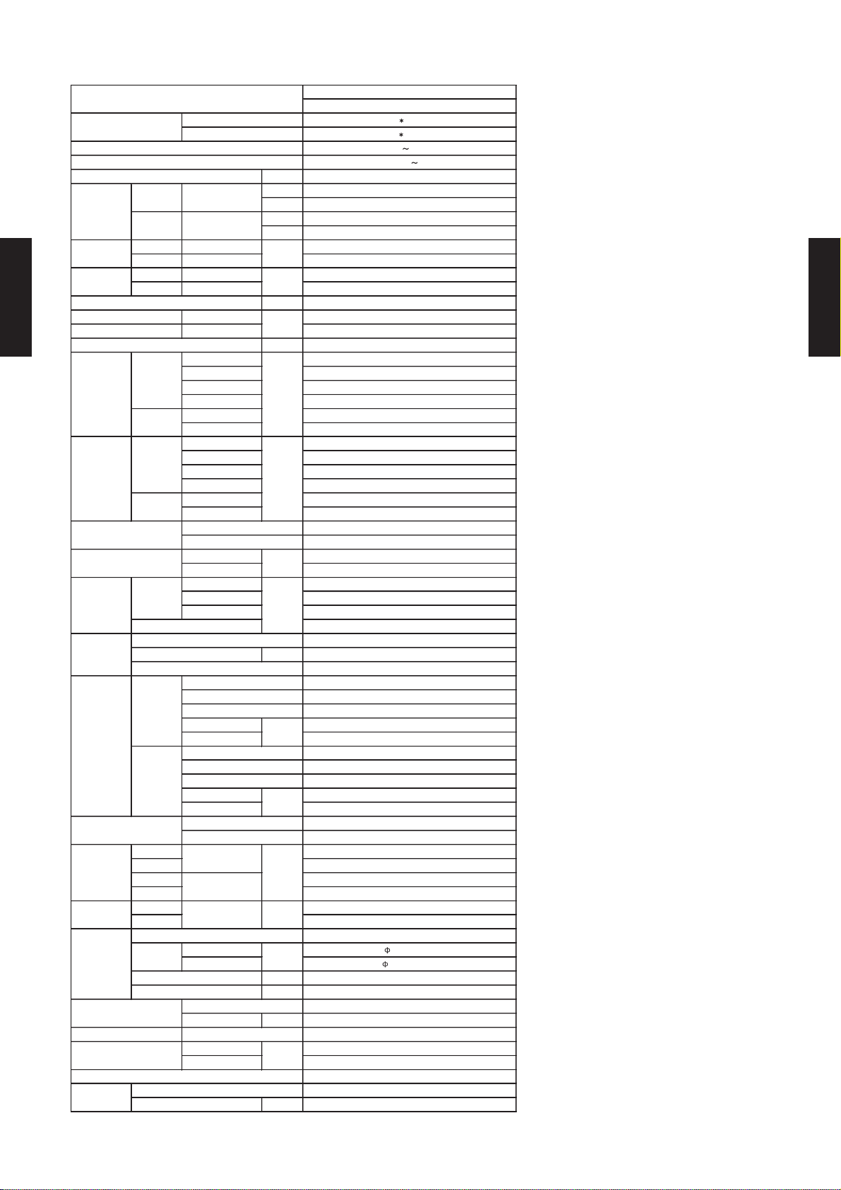
3-4. DIMENSIONS
3-4-1. OUTDOOR UNIT
MODEL : AO 24L
350
900
FLOOR / CEILING TYPE
AB24
900
930
Side view
(Unit : mm)
FLOOR / CEILING TYPE
AB24
Front view
804
Bottom view
MOUNTING POSITION
300 mm
(12") or
over
AIR
600 mm
(24") or over
300 mm
(12") or over
300 mm
(12") or
over
333
19
600 mm
(24") or over
- (03 - 05) -
Page 7
3-4-2. INDOOR UNIT
MODEL : AB 24L
6
FLOOR / CEILING TYPE
AB24
1 2
Side view
1
2
Back view
(Unit : mm)
45
FLOOR / CEILING TYPE
AB24
3
1
Refrigerant piping flare connection (Gas)
2
Refrigerant piping flare connection (Liquid)
3
Drain piping connection (Drain pipe : I.D. 25 O.D. 29 L 700)
4
Knock out hole for drain piping
5
Knock out hole for refrigerant piping
6
Hole for lifting bolt (Use M10 screw bolt)
990
500 245
65
655
530
45
125
100 hole
50 hole
100 hole
Wall bracket
Side of set
65
Bottom view
3
- (03 - 06) -
Page 8
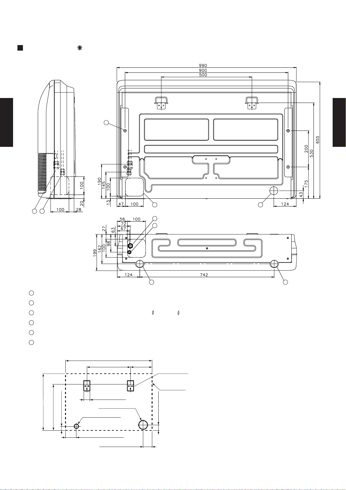
MOUNTING POSITION
Floor
(Unit : mm)
Left Right
FLOOR / CEILING TYPE
AB24
300 or more300 or more
Ceiling
FLOOR / CEILING TYPE
AB24
Left
150 or more 300 or more
Indoor unit
Ceiling
2300 or more
20 or more
1000 or more
Obstruction
Right
- (03 - 07) -
Page 9

3-5. REFRIGERANT CIRCUIT
MODELS : AB 24L / AO 24L
FLOOR / CEILING TYPE
AB24
FLOOR / CEILING TYPE
AB24
- (03 - 08) -
Page 10

3-6. WIRING DIAGRAMS
3-6-1. OUTDOOR UNIT
MODEL : AO 24L
FLOOR / CEILING TYPE
AB24
FLOOR / CEILING TYPE
AB24
TO INDOOR UNIT
- (03 - 09) -
TO POWER SUPPLY
Page 11
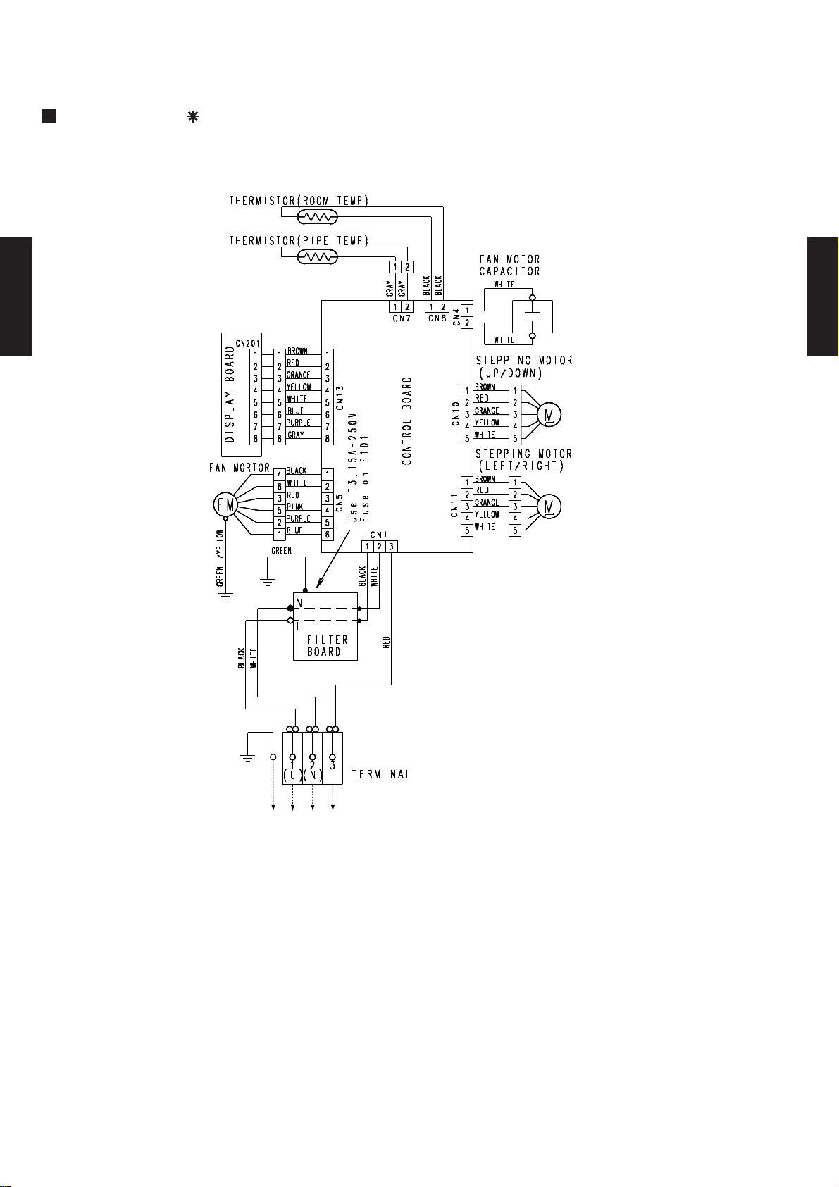
3-6-2. INDOOR UNIT
MODEL : AB 24L
FLOOR / CEILING TYPE
AB24
FLOOR / CEILING TYPE
AB24
TO OUTDOOR UNIT
- (03 - 10) -
Page 12

3-7. CAPACITY TABLE
AFR 14.7
TC SHC PI T C SHC PI TC SHC PI TC SHC PI TC SHC PI TC SHC PI TC SHC PI TC SHC PI
0 4.92 4.28 0.45 5.02 4.04 0.46 5.12 4.27 0.46 5.26 4.44 0.47 5.33 4.41 0.47 5.44 4.33 0.48 5.49 4.29 0.48 5.54 4.47 0.48
5 5.06 4.37 0.57 5.17 4.14 0.58 5.30 4.41 0.59 5.49 4.63 0.60 5.56 4.61 0.60 5.70 4.54 0.61 5.76 4.50 0.61 5.82 4.70 0.62
10 6.00 5.18 0.90 6.15 4.91 0.92 6.30 5.23 0.93 6.55 5.53 0.95 6.65 5.51 0.96 6.83 5.45 0.97 6.91 5.41 0.98 6.99 5.65 0.98
15 5.64 4.85 0.99 5.78 4.58 1.02 5.93 4.91 1.03 6.16 5.20 1.05 6.26 5.18 1.06 6.44 5.13 1.07 6.52 5.10 1.08 6.60 5.35 1.09
20 5.53 4.74 1.12 5.65 4.47 1.14 5.79 4.79 1.15 6.01 5.07 1.18 6.11 5.06 1.19 6.28 5.01 1.21 6.37 4.99 1.22 6.45 5.24 1.23
25 7.16 6.16 1.84 7.34 5.83 1.86 7.50 6.22 1.88 7.78 6.57 1.90 7.90 6.54 1.92 8.12 6.47 1.94 8.22 6.44 1.95 8.31 6.74 1.96
30 6.84 5.85 2.07 7.03 5.57 2.09 7.19 5.96 2.10 7.46 6.30 2.14 7.59 6.28 2.15 7.81 6.23 2.18 7.91 6.20 2.19 8.02 6.52 2.21
35 7.25 6.18 2.86 7.39 5.82 2.87 7.58 6.26 2.90 7.86 6.64 2.94 8.00 6.62 3.17 8.26 6.58 3.00 8.38 6.56 3.02 8.50 6.92 3.04
40 6.83 5.80 3.18 6.93 5.45 3.19 7.09 5.86 3.21 7.38 6.24 3.26 7.52 6.23 3.28 7.78 6.20 3.33 7.91 6.19 3.35 8.04 6.56 3.40
43 6.49 5.48 3.29 6.60 5.17 3.30 6.76 5.57 3.32 7.05 5.96 3.37 7.20 5.96 3.39 7.46 5.94 3.44 7.61 5.94 3.46 7.75 6.31 3.49
Outdoor temperature
Indoor temperature
TC PI TC PI TC PI T C PI TC PI TC PI TC PI
-10 -11 6.92 2.99 6.81 3.08 6.60 3.18 6.39 3.27 6.28 3.32 6.07 3.42 5.86 3.46
-5 -6 6.80 3.00 6. 71 3.09 6.52 3.18 6.33 3.26 6.23 3.31 6.04 3.40 5.85 3.44
0 -1 7.09 2.96 7.00 3.03 6.82 3.11 6.65 3.19 6.56 3.23 6.38 3.30 6.20 3.34
2 1 7. 31 3.07 7.23 3.13 7.09 3.20 6.94 3.26 6.86 3.30 6.71 3.36 6.56 3.40
7 6 9. 27 2.81 9.18 2.87 9.00 3.17 8.82 2.99 8.73 3.02 8.55 3.08 8.37 3.11
10 8 9.64 2.88 9.55 2.94 9.37 2.99 9.20 3.05 9.11 3.08 8.94 3.13 8.76 3.16
15 12 9.87 2.93 9.78 2.99 9.61 3.04 9.43 3.10 9.34 3.13 9. 16 3.18 8.98 3.21
20 15 10.06 2.87 9.97 2.93 9.77 2.99 9.58 3.04 9. 48 3.07 9.28 3.13 9.09 3.16
24 18 10.22 2.81 10.11 2.87 9.90 2.93 9.69 2.99 9.59 3.03 9.37 3.09 9.16 3.12
Outdoor temperature
Indoor temperature
MODELS : AB 24L / AO 24L
COOLING
18 °CDB
(°CDB)
FLOOR / CEILING TYPE
AB24
15 °CWB
26 °CDB23 °CDB21 °CDB
18 °CWB 19 °CWB
27 °CDB 30 °CDB
29 °CDB 32 °CDB
21 °CWB16 °CWB 22 °CWB12 °CWB
23 °CWB
FLOOR / CEILING TYPE
AB24
HEATING
AFR 14.7
27 °CDB 30 °CDB25 °CDB23 °CDB16 °CDB 18 °CDB 20 °CDB
(°CDB) (°CW B)
AFR: Air flow rate (m3/min)
TC : Total capacity (kW)
SHC: Sensible Heat capacity (kW)
PI : Power Input (kW)
- (03 - 11) -
Page 13

3-8. CAPACITY COMPENSATION FOR PIPE LENGTH
7.5 10 15 20 25
- - - - -
15 - - 0.982 0.974 0.966
10 - 0.988 0.982 0.974 0.966
7.5 1.000 0.988 0.982 0.974 0.966
5 1.000 0.988 0.982 0.974 0.966
0 1.000 0.988 0.982 0.974 0.966
-5 0.992 0.980 0.974 0.966 0.958
-7.5 0.988 0.976 0.970 0.962 0.954
-10 - 0.972 0.966 0.958 0.950
-15 - - 0.958 0.951 0.943
- - - - -
COOLING
HEIGHT DIFFERENCE (m)
Outdoor unit is
up-side
Outdoor unit
is bottom-side
PIPE LENGTH (m)
7.5 10 15 20 25
- - - - -
15 - - 0.987 0.985 0.983
10 - 0.993 0.992 0.990 0.988
7.5 0.993 0.996 0.994 0.992 0.991
5 0.995 0.998 0.997 0.995 0.993
0 1.000 1.003 1.002 1.000 0.998
-5 1.000 1.003 1.002 1.000 0.998
-7.5 1.000 1.003 1.002 1.000 0.998
-10 - 1.003 1.002 1.000 0.998
-15 - - 1.002 1.000 0.998
- - - - -
PIPE LENGTH (m)
Outdoor unit
is bottom-side
Outdoor unit is
up-side
HEIGHT DIFFERENCE (m)
HEATING
AND HEIGHT DIFFERENCE
MODELS : AB 24L / AO 24L
FLOOR / CEILING TYPE
AB24
FLOOR / CEILING TYPE
AB24
- (03 - 12) -
Page 14

3-9. ADDITIONAL CHARGE CALCULATION
REFRIGERANT TYPE
REFRIGERANT AMOUNT g
R410A
1850
PIPE LENGTH m
10 15 20 25 (MAX)
ADDITIONAL CHARGE g
0 (Charge less)
+250 +500 +750
50g/m
MODELS : AB 24L / AO 24L
REFRIGERANT CHARGE
FLOOR / CEILING TYPE
AB24
FLOOR / CEILING TYPE
AB24
- (03 - 13) -
Page 15
3-10. OPERATION RANGE
Indoor unit Outdoor unit Indoor temperature Indoor humidity Outdoor temperature
Cooling
Dry
18 to 32 °C About 80% or less 0 to 43 °C
Heating 16 to 30 °C - -10 to 24 °C
Model
Operation Range
AB 24L
AO 24L
Mode
FLOOR / CEILING TYPE
AB24
FLOOR / CEILING TYPE
AB24
- (03 - 14) -
Page 16

3-11. FAN PERFORMANCE AND AIR FLOW
3-11-1. AIR VELOCITY DISTRIBUTION
MODEL : AB 24L (FLOOR CONSOLE)
(m)
2
1
0
2.0
1.0
1
2
0123456 789
FLOOR / CEILING TYPE
AB24
(m)
3
2
1.0
0.5
1
0
2.0
1
2
1.0
0.5
3
0123456789
Unit : m/s
0.5
0.25
Unit : m/s
0.25
HORIZONTAL: Right
HORIZONTAL: Left
0.25
TOP VIEW
VERTICAL : Forward
HORIZONTAL : Center
(m)
TOP VIEW
VERTICAL : Forward
HORIZONTAL : Right & Left
(m)
Note :
Condition
Fan speed : High
Operation mode :FAN
FLOOR / CEILING TYPE
AB24
(m)
Unit : m/s
3
2
1
2.0
1.0
0.5
0.25
012 3 456 78 9
0.5
0.25
Unit : m/s
SIDE VIEW
VERTICAL : Center
HORIZONTAL : Center
(m)
(m)
3
2
1
0123456
1.0
2.0
SIDE VIEW
VERTICAL : Forward
HORIZONTAL : Center
(m)
(m)
3
2
1
0123456
Unit : m/s
0.5
0.25
1.0
2.0
SIDE VIEW
VERTICAL : Up
HORIZONTAL : Center
(m)
- (03 - 15) -
Page 17

MODEL : AB 24L (UNDER CEILING)
(m)
2
1
0
2.0
1.0
1
2
0123456 789
FLOOR / CEILING TYPE
AB24
(m)
3
2
1.0
1
2.0
0
1
2
1.0
3
0123456789
Unit : m/s
0.5
Unit : m/s
0.25
0.5
HORIZONTAL: Right
HORIZONTAL: Left
0.5
0.25
0.25
TOP VIEW
VERTICAL : Up
HORIZONTAL : Center
(m)
TOP VIEW
VERTICAL : Up
HORIZONTAL : Right & Left
(m)
Note :
Condition
Fan speed : High
Operation mode :FAN
FLOOR / CEILING TYPE
AB24
(m)
Unit : m/s
3
2
1
2.0
1.0
0.5
0.25
012 3 456 78 9
(m)
Unit : m/s
3
2
1
0123456
2.0
1.0
0.5
0.25
SIDE VIEW
VERTICAL : Center
HORIZONTAL : Center
(m)
SIDE VIEW
VERTICAL : Up
HORIZONTAL : Center
(m)
(m)
3
2
2.0
1
0123456
1.0
0.5
Unit : m/s
0.25
SIDE VIEW
VERTICAL : Down
HORIZONTAL : Center
(m)
- (03 - 16) -
Page 18
3-11-2. AIR FLOW
m3/h
880
m3/h
740
m3/h
630
m3/h
3320
1180
1040
900
735
Indoor unit
Outdoor unit
FAN SPEED
NUMBER OF
ROTATIONS
(r.p.m)
AIR FLOW
HIGH
MED
LOW
HIGH
MODELS : AB 24L / AO 24L
FLOOR / CEILING TYPE
AB24
l/s 244
CFM 518
l/s 206
CFM 435
l/s 175
CFM 371
l/s 922
FLOOR / CEILING TYPE
AB24
CFM 1954
- (03 - 17) -
Page 19

3-12. NOISE LEVEL CURVE
3-12-1. OUTDOOR UNIT
COOLING
MODEL : AO 24L
80
70
NC-65
60
50
FLOOR / CEILING TYPE
AB24
40
30
20
Octave band sound pressure level, dB:(0dB=0.0002µbar)
10
NC-60
NC-55
NC-50
NC-45
NC-40
NC-35
NC-30
NC-25
NC-20
NC-15
HEATING
MODEL : AO 24L
80
70
60
50
40
30
20
Octave band sound pressure level, dB:(0dB=0.0002µbar)
10
NC-65
NC-60
NC-55
NC-50
NC-45
NC-40
NC-35
NC-30
NC-25
NC-20
NC-15
FLOOR / CEILING TYPE
AB24
0
63 125 250 500 1,000 2,000 4,000 8,000
Octave band center frequency,Hz
0
63 125 250 500 1,000 2,000 4,000 8,000
Octave band center frequency,Hz
- (03 - 18) -
Page 20

SOUND LEVEL CHECK POINT
FLOOR / CEILING TYPE
AB24
FLOOR / CEILING TYPE
AB24
- (03 - 19) -
Page 21

3-12-2. INDOOR UNIT (UNDER CEILING INSTLLATION)
HIGH
LOW
HIGH
LOW
COOLING
MODEL : AB 24L
80
70
NC-65
60
50
FLOOR / CEILING TYPE
AB24
40
30
20
Octave band sound pressure level, dB:(0dB=0.0002µbar)
10
NC-60
NC-55
NC-50
NC-45
NC-40
NC-35
NC-30
NC-25
NC-20
NC-15
HEATING
MODEL : AB 24L
80
70
60
50
40
30
20
Octave band sound pressure level, dB:(0dB=0.0002µbar)
10
NC-65
NC-60
NC-55
NC-50
NC-45
NC-40
NC-35
NC-30
NC-25
NC-20
NC-15
FLOOR / CEILING TYPE
AB24
0
63 125 250 500 1,000 2,000 4,000 8,000
Octave band center frequency,Hz
0
63 125 250 500 1,000 2,000 4,000 8,000
Octave band center frequency,Hz
- (03 - 20) -
Page 22

SOUND LEVEL CHECK POINT
UNDER CEILING
1m
1
MIC
FLOOR / CEILING TYPE
AB24
1 0.8m (For AB12 AB24)
1m (For AB30 AB54)
FLOOR / CEILING TYPE
AB24
- (03 - 21) -
Page 23

3-13. ELECTRIC CHARACTERISTICS
Main Fuse (Circuit breaker)
Current
Model Name
Outdoor Fan Motor
0.14
0.6
20
Indoor Fan Motor
0.106
0.44
25
3.5
Rated Value
Mode
*1) Wiring Spec
Power Supply
230
50
AB 24L
AO 24L
MODELS : AB 24L / AO 24L
Indoor unit
Outdoor unit
Voltage V
Frequency Hz
Current A 9.4 8.7
Input kW 2.15 1.99
Max Operating Current A 12.5 12.5
FLOOR / CEILING TYPE
AB24
Starting Current A 10 10
Cooling Heating
FLOOR / CEILING TYPE
AB24
A
Power Cable
mm
2
*2)Limited wiring length m
Input kW
Full Load Amp. A
Input kW
Full Load Amp. A
*1) Wiring Spec : Selected Sample
(Selected based on Japan Electrotechnical Standard and Codes Committee E0005)
*2) Limited Wiring length : This is the wiring length in case voltage descent is less than 2%.
When the wiring length becomes long, please select the wiring of a more larger
diameter.
- (03 - 22) -
Page 24

3-14. SAFETY DEVICE
AO 24L
FUSE
(SIDE OF POWER SUPPLY TERMINAL)
OFF 130±5°C
ON 80±17°C
AB 24L
OUTDOOR UNIT
FUSE (ON MAIN PCB) - 3.15A 250V
FAN MOTOR PROTECTOR THERMAL PROTECTOR 150±5°C OFF
COMPRESSOR THERMAL PROTECTOR
FLOOR / CEILING TYPE
AB24
INDOOR UNIT
FUSE - 3.15A 250V
FAN MOTOR PROTECTOR THERMAL PROTECTOR 140±5°C OFF
PROTECTION FORM
- 25A 250V
PROTECTION FORM
FLOOR / CEILING TYPE
AB24
- (03 - 23) -
Page 25

3-15. FUNCTION SETTING
Auto restart validity/invalidity
Room temperature correct coefficient
Room temperature correct coefficient
Forbidden
Jumper Wire
JM1
JM212
INDOOR UNIT
DIP SW
3
JM3
SW 1
Remote control unit signal code
3-15-1. INDOOR UNIT
FLOOR / CEILING TYPE
SWITCH POSITION
AB24
FLOOR / CEILING TYPE
AB24
Indoor unit control circuit board
ON OFF
3
2
1
JM1
JM2
JM3
- (03 - 24) -
Page 26
3-15-2. SWITCH FUNCTION (INDOOR UNIT)
SW 1-1
SW state
OFF
Invalidity
ON
Validity
0 deg
0 deg
0 deg
cooling
-2 deg
SW 1-2
SW 1-3
0 deg
heating
dry
-2 deg
-2 degONONONOFF
OFF
+2 deg
-2 deg
OFF
SW state
-2 deg
OFF
ON
0 deg
+4 deg
BCD
Disconnect
Disconnect
Disconnect
Disconnect
connect
connect
JM3
Remote control unit
signal code
connect
connect
A
JM2
Jumper wire
DIP SWITCH SETTING
SW1-1. Auto restart setting
Auto restart function can be selected by turning this switch ON/OFF.
AUTO RESTART SETTING
( Factory setting)
FLOOR / CEILING TYPE
SW1-2, 1-3. Room temperature correct coefficient of heating.
AB24
Decide the heating temperature correct coefficient value of heating.
TEMPERATURE CORRECTION
( Factory setting)
FLOOR / CEILING TYPE
AB24
JUMPER WIRE SETTING
JM1 setting forbidden
JM2, 3 setting
( Factory setting)
- (03 - 25) -
 Loading...