

General ABGA30TATA, ABGA36TATA, ABGA45TATA, AUGA25TATA, AUGA30TATA Installation Manual
...
CONNECTION PIPE REQUIREMENT
Small Large
Diameter
45,000 / 36,000 BTU/h class 9.52 mm 19.05 mm
30,000 BTU/h class 9.52 mm 15.88 mm
Table 1
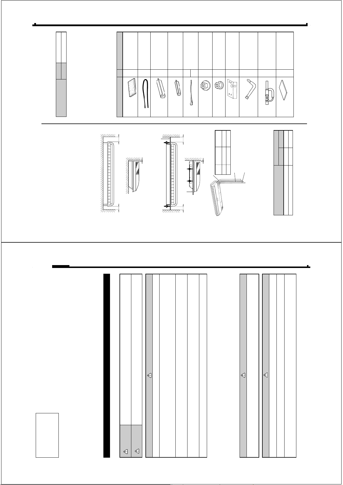
Drain hose insulation Adhesive type 70 × 230
VT wire For fixing the drain hose
L 280 mm
Coupler heat insulation For indoor side pipe joint
(large) (large pipe)
Coupler heat insulation For indoor side pipe joint
(small) (small pipe)
Nylon fastener For fixing the coupler
heat insulation
Special nut A For installing indoor unit
(large flange)
Special nut B For installing indoor unit
(small flange)
Installation For positioning the
template indoor unit
Auxiliary pipe assembly For connecting the piping
Indoor capillary tube (This part is enclosed with
the 30,000 and 36,000
BTU/h versions.)
BR sheet 65 × 130 × T5
(This part is enclosed with
the 30,000 and 36,000
BTU/h versions.)
STANDARD PARTS
The following installation parts are furnished. Use them as required.
INDOOR UNIT ACCESSORIES
Description Q’ty Application
1
1
2
1
4
4
1
1
1
2
Large
4
Small
4
ELECTRICAL REQUIREMENT
• Use 0.7 mm to 1.2 mm thick pipe.
• Use pipe with water-resistant heat insulation.
• Use pipe that can withstand a pressure of 3,040 kPa.
MAX
Connection cord (mm
2
)
2.5
Table 2
MIN
1.5
• Always use H07RN-F or equivalent to the connection cord.
• Install the disconnection device with a contact gap of at least
3 mm nearby the units. (Both indoor unit and outdoor unit)
INDOOR UNIT
(1) Install the indoor unit level on a strong wall which is not
subject to vibration.
(2) The inlet and outlet ports should not be obstructed : the air
should be able to blow all over the room.
(3) Do not install the unit where it will be exposed to direct
sunlight.
(4) Install the unit where connection to the outdoor unit is easy.
(5) Install the unit where the drain pipe can be easily installed.
(6) Take servicing, etc. into consideration and leave the spaces
shown in (Fig. 1 or 2). Also install the unit where the filter can
be removed.
45,000/36,000 30,000
BTU/h class BTU/h class
Large ø19.05 mm ø15.88 mm
Small ø9.52 mm ø9.52 mm
Fig. 1
Connection cord
1.5 to 2.5 mm
2
(H07RN-F or equivalent)
Drain pipe
VP25
(General polyvinyl chloride pipe)
Ceiling
3" (80 mm)
or over
INDOOR UNIT
0.4" (10 mm)
or over
6" (150 mm)
or over
Ceiling panel
0.4" (10 mm)
or over
Ceiling panal
INDOOR UNIT
Ceiling
3" (80 mm)
or over
6" (150 mm)
or over
Connection pipe
Fig. 3
[FOR HALF CONCEALED INSTALLATION]
Fig. 2
Ceiling Suspension Type
R407C
Refrigerant
SPLIT TYPE AIR CONDITIONER
This air conditioner uses new refrigerant HFC (R407C).
INSTALLATION INSTRUCTION SHEET
(PART NO. 9363005028)
This mark indicates procedures which, if improperly performed, might lead to the death or serious
injury of the user.
This mark indicates procedures which, if improperly performed, might possibly result in personal
harm to the user, or damage to property.
CAUTION!
WARNING!
For authorized service personnel only.
WARNING
set available from our standard parts.
only.
standard parts. This installation instruction sheet describes the correct connections using the installation
2 Connect the indoor unit and outdoor unit with the room air conditioner piping and cords available from our
3 Installation work must be performed in accordance with national wiring standards by authorized personnel
1 For the air conditioner to operate satisfactorily, install it as outlined in this installation instruction sheet.
a flame, it produces a toxic gas.
4 If refrigerant leaks while work is being carried out, ventilate the area. If the refrigerant comes in contact with
5 Do not turn on the power until all installation work is complete.
• Be careful not to scratch the air conditioner when handling it.
• After installation, explain correct operation to the customer, using the operating manual.
serviced or moved.
• Let the customer keep this installation instruction sheet because it is used when the air conditioner is
SELECTING THE MOUNTING POSITION
WARNING
CAUTION
Install at a place that can withstand the weight of the indoor and outdoor units and install positively so that the
units will not topple or fall.
2 Do not install the unit near a source of heat, steam, or flammable gas.
cannot reach the unit.
3 If children under 10 years old may approach the unit, take preventive measures so that they
Decide the mounting position with the customer as follows:
1 Do not install where there is the danger of combustible gas leakage.
Special nut B
(Included)
M10 Nut
(Obtained locally)
10 to 15 mm
M10 Anchor Bolt
(Obtained locally)
Ceiling
sion fittings at the sides (four places), and slide the unit back
(See Fig. 13).
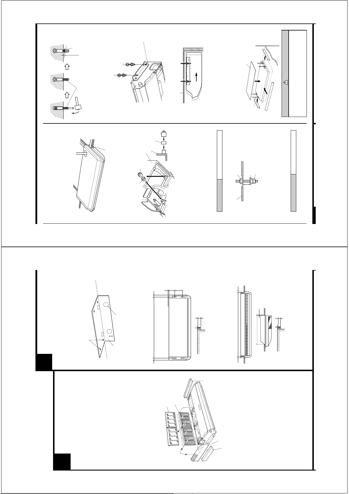
4. INSTALLING THE INDOOR UNIT
(1) Lift unit so that suspension bolts pass through the suspen-
piping
Fig. 12
Cut off the piping outlet cutting groove
with a hacksaw, etc.
Fig. 11
3 Right
1 Right rear piping
(Connection pipe only)
2 Top piping
(Drain pipe only)
4 Left rear piping
2. SELECT PIPING DIRECTION.
Select connection piping and drain piping directions (Fig.8).
Fig. 8
(Drain pipe only)
5 Left piping
INDOOR UNIT (TOP VIEW)
Ceiling
• Transfer the Drain cap and Drain cap seal.
[For 4 Left rear piping, 5 Left piping]
Fig. 9
Indoor unit
Drain cap seal
Drain cap
Drain cap seal
Wall
Drain pan
Drain cap
Wall
Ceiling panel
Fig. 13
Push cap all the way on
(as far as it will go).
THE SUSPENSION BOLTS
3. DRILLING THE HOLES AND ATTACHING
Glass wool insulate
INDOOR UNIT
“B” bolts and the M10 nuts. Make sure that unit is secure and
will not shift back and forth.
(2) Fasten the indoor unit into place by tightening-up the special
[For Half-Concealed Installation]
When installing the indoor unit in a semi-concealed orientation,
Bolt Strength 980 to 1470 N (100 to 150 kgf)
and a normal M10 nut to each bolt. (The two special nuts are
provided with the unit. The M10 nut must be obtained
locally.) Refer to Fig. 10.
(1) Drill ø25mm holes at the suspension-bolt locations.
(2) Install the bolts, then temporarily attach Special nuts A and B
(10 to 20mm thick)
(Top Viev)
INDOOR UNIT
make sure to reinforce the insulation of the unit on all sides. Drops
of water may fall from the unit if it is not thoroughly insulated.
Fig. 14
M10 Nut (Obtained locally)
Special nut B (Included)
Special nut A (Included)
10 to 15 mm
Ceiling panel
Fig. 10
[If using anchor bolts]
Wall
Ceiling
panel
CAUTION
In order to check the drainage, be sure to use a
level during installation of the indoor unit. If the
installation site of the indoor unit is not level,
water leakage may occur.
set the suspension bolts. Note that anchor bolts are M10
bolts (to be obtained locally).
(1) Drill holes for anchor bolts at the locations at which you will
ANCHOR-Bolt Strength 980 to 1470 N (100 to 150 kgf)
“B” (included) and a locally-procured M10 nut to each of the
bolts. (See Fig. 11.)
(2) Install the anchor bolts, then temporarily attach special nut
INDOOR UNIT
INSTALLATION
You can use the accessory template to help you install the indoor
unit. The template helps you determine the appropriate locations
for suspension bolts and pipe openings (drain pipe and connec-
tion cord).
2
INSTALLATION PROCEDURE
Install the air conditioner as follows:
Fig. 5
UNIT INSTALLATION
PREPARING INDOOR
1
Ceiling
Wall
Drilling position for piping
Drilling position for Suspension bolt
REMOVE THE INTAKE GRILLE AND SIDE
COVER.
(1) Remove the two Air filters (Fig.4).
Template
and intake grilles at three places. (Refer to “2 INDOOR
UNIT INSTALLATION”.)
• For 4 Left rear drain and 5 Left drain: Remove air filters
(Right and Left side).
(2) Remove the two Intake grilles (Fig.4).
• For 5 Left drain : Remove both the Side cover A
(3) Remove the Side cover A (Right side) and Side cover B
10 mm
155 mm
for Installation)
300 mm
INDOOR UNIT (TOP VIEW)
30 mm
Dimensions
(Space Required
Suspension bolt pitch 1600 mm
BOLTS
1. LOCATION OF CEILING SUSPENSION
Fig. 6
30 mm
Intake grille
Air filter
(Right and Left side). (Refer to “2 INDOOR UNIT
INSTALLATION”.)
information about how to install for fresh-air intake, refer to
“0 FRESH-AIR INTAKE”.
(4) This air conditioner can be set up to intake fresh air. For
Fig. 4
Tapping screw
Suspension bolt should
extend outward 30 to 75 mm.
INDOOR UNIT
• Suspension-bolt pitch should be as shown in Fig. 6.
[For Half-Concealed Installation]
(Left side)
Side cover B
INDOOR UNIT
Side cover A (Right side)
40 mm
Ceiling panel
Ceiling Opening: 1580 mm
40 mm
Fig. 7
Side cover B (Right side)
15 mm
Ceiling panel
Suspension bolt should
Ceiling Opening: 640 mm
extend outward 30 to 50 mm.
INDOOR UNIT
Indoor
capillary tube
Tape
Binder
Branch liquid pipe
Fig. 24
Fig. 23
BR sheet
Connection
pipe
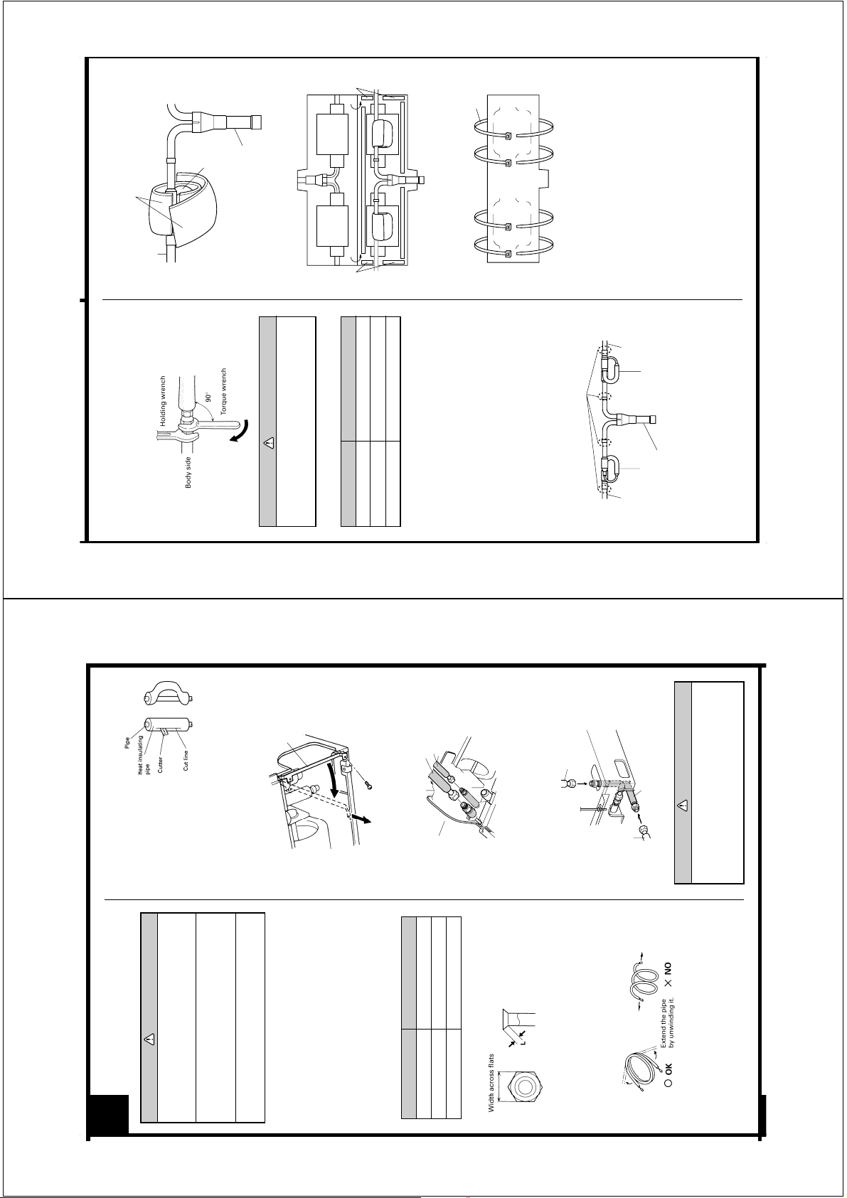
CAUTION
Hold the torque wrench at its grip, keeping it in the
When the flare nut is tightened properly by your hand, hold the
body side coupling with a separate spanner, then tighten with a
torque wrench (Fig. 21).
Fig. 21
right angle with the pipe as shown in Fig. 21, in
Tape
310 to 350 kgf • cm (30.4 to 34.3 N • m)
750 to 800 kgf • cm (73.5 to 78.4 N • m)
800 to 1,000 kgf • cm (78.4 to 98 N • m)
Table 4 : Flare nut tightening torque
Pipe Tightening torque
order to tighten the flare nut correctly.
Small pipe (9.52 mm dia.)
Large pipe (15.88 mm dia.)
Large pipe (19.05 mm dia.)
Fig. 25
Brazing (all around)
CONNECTING AN INDOOR CAPILLARY TUBE
4.
branch liquid pipe) as shown in Fig. 22.
shown in Fig. 23.
with insulation (Fig. 24) and affix the insulation with tape.
These instructions refer to the 30,000 and 36,000 BTU/h versions.
Installation Procedure
(1) Braze each part (connection pipe, indoor capillary tube, and
(2) Wrap the two BR sheets around the indoor capillar y tube as
(3) Cover the indoor capillary tube and the branch liquid pipe
struction sheet for the outdoor unit for details.
(4) Secure the insulation using the binders (Fig. 25).
• If the joint pipe must be installed, refer to the installation in-
Fig. 22
Indoor
unit side
Indoor
unit side
Connection
pipe
Indoor capillary tube Indoor capillary tube
Connection
pipe
Outdoor unit side
Branch liquid pipe
Fig. 17
When bending the pipe, do not
bend it as is. The pipe will be
collapsed. In this case, cut the
heat insulating pipe with a
sharp cutter as shown in Fig.
17, and bend it after exposing
the pipe. After bending the pipe
as you want, be sure to put the
heat insulating pipe back on
the pipe, and secure it with
tape.
CAUTION
THE PIPING
CONNECTING
Prevent mineral oil from getting into the system
as this would reduce the lifetime of the units.
3
1 Do not use mineral oil on flared part.
Filter guide
Indoor unit
3. CONNECTION PIPES
(1) Remove the filter guide (Fig. 18).
Fig. 18
previous installations. Only use parts which are
delivered with the unit.
2 Never use piping which has been used for
nitrogen gas through them.
3 While welding the pipes, be sure to blow dry
is not deformed.
the pipe and remove the burrs.
unit and assemble as shown in (Table 3) and insert the
flare nut onto the pipe, and flare with a flaring tool.
1. FLARE PROCESSING
(1) Cut the connection pipe with pipe cutters so that the pipe
(2) Holding the pipe downwards so that cuttings cannot enter
and that there are no cracks.
(3) Remove the flare nut from the indoor unit pipe and outdoor
(4) Check if the flared part “L” (Fig. 15) is spread uniformly
Small pipe
Large pipe
Indoor unit
(2) Attach the connection pipe (Fig. 19).
Fig. 19
L dimension
Small (width across flats 22 mm)
Large (width across flats 27 mm)
Table 3
Pipe Flare nut
Large (width across flats 36 mm)
Small pipe (9.52 mm dia.)
Large pipe (15.88 mm dia.)
Large pipe (19.05 mm dia.)
Fig. 15
Large pipe
33
33
3 Right piping connections, use
22
22
2 Top piping and
For
•
the Auxiliary pipe (large pipe) provided.
22
22
2 Top piping
Fig. 20
Small pipe (9.52 mm dia.)
1.8 to 2.0 mm
Large pipe (15.88 mm dia.)
2.2 to 2.4 mm
Large pipe (19.05 mm dia.)
2.6 to 3.0 mm
2. BENDING PIPES
Indoor unit (rear)
CAUTION
Auxiliary pipe (large pipe)
Large pipe
33
33
3 Right piping
Be sure to apply the pipe against the port on the
indoor unit correctly. If the centering is improper,
the flare nut cannot be tightened smoothly. If
the flare nut is forced to turn, the threads will be
damaged.
The pipes are shaped by your hands. Be careful not to collapse
them.
Fig. 16
Do not bend the pipes in an angle more than 90°.
When pipes are repeatedly bent or stretched, the material will
harden, making it difficult to bend or stretch them any more.
Do not bend or stretch the pipes more than three times.
 Loading...