

Generac Power Systems 005796-0 (XG6500), XG7000, XG7OOOE, XGSO00, XGS000E Owner's Manual
...Page 1

GENERAC _
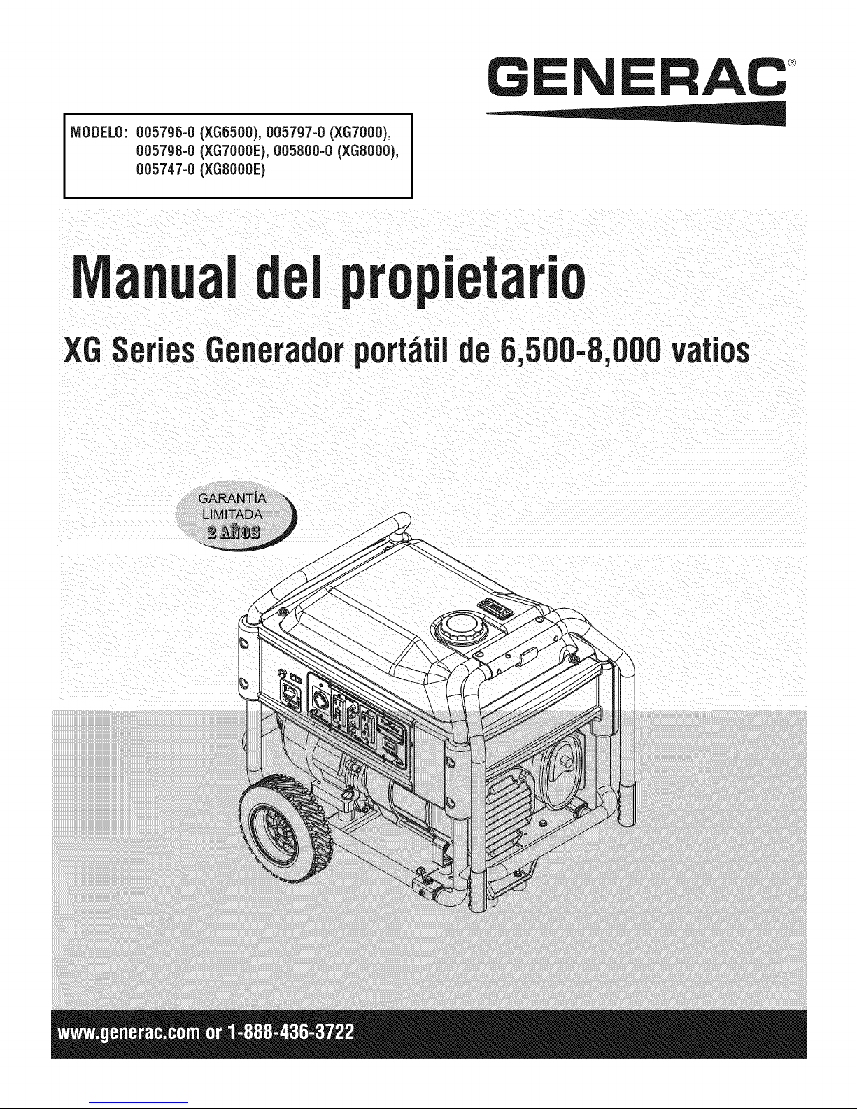
MODELS:
005796-0 (XG6500), 005797-0 (XG7000),
005798-0 (XG7OOOE),005800-0 (XGSO00),
005747-0 (XGS000E)
0wnsr's
XGSeries6,500-8,
L M|TED
WattPorta e Generator
Page 2

introduction.............................................................1
Readthis iVlanualThoroughly.................................1
Safety Rules...........................................................1
StandardsIndex.............................................................3
Generalinformation................................................4
1.1 Unpacking......................................................................4
1.1.1 AccessoryBox..................................................4
1.2 Assembly.......................................................................4
1.2.1 Assemblingthe WheelKitand FrameFoot..........4
Operation................................................................5
2.1 Knowthe Generator.......................................................5
2.1.1 BatteryConnection(XG7000E& XG8000E).......6
2.2 Hourmeter......................................................................6
2.3 CordSetsandConnectionPlugs....................................6
2.3.1 120 VAC,20 Amp, GFCIDuplexReceptacle.......6
2.3.2 120/240 VAC,30Amp Receptacle.....................6
2.4 How to Usethe Generator..............................................7
2.4.1 SystemGround..................................................7
2.4.2 GroundingtheGenerator....................................7
2.4.3 Neutralto FrameGrounding...............................8
2.4.4 ConnectingElectricalLoads...............................8
2.5 Don't Overloadthe Generator..........................................8
2.6 WattageReferenceGuide...............................................8
2.7 BeforeStartingthe Generator.........................................9
2.7.1 AddingEngineOil ..............................................9
2.7.2 AddingGasoline.................................................9
2.8 ToStartthe Engine.......................................................10
2.8.1 Manual(Recoil)Starting..................................10
2.8.2 ElectricStarting(XG7000E& XG8000E)..........11
2.9 Stoppingthe Engine.....................................................11
2.10 Low Oil PressureShutdownSystem.............................11
2.10.1 Restarting........................................................11
2.11 Charginga Battery.......................................................11
Maintenance.........................................................11
3.1 MaintenanceSchedule.................................................11
3.2 ProductSpecifications..................................................11
3.2.1 GeneratorSpecifications..................................11
3.2.2 EngineSpecifications.......................................12
3.2.3 EmissionsInformation.....................................12
3.3 GeneralRecommendations...........................................12
3.3.1 GeneratorMaintenance....................................12
3.3.2 ToCleanthe Generator.....................................13
3.3.3 EngineMaintenance.........................................13
3.3.4 CheckingOilLevel...........................................13
3.3.5 Changingthe Oiland Oil Filter..........................13
3.3.6 Replacingthe SparkPlug.................................13
3.4 ServiceAir Cleaner.......................................................13
3.5 CleanSparkArrestorScreen.........................................14
3.6 General........................................................................14
3.7 LongTermStorage.......................................................14
3.8 OtherStorageTips.......................................................15
BatteryService.....................................................15
4.1 BatteryReplacement(XG7000E& XG8000E)...............15
Troubleshooting....................................................16
5.1 TroubleshootingGuide..................................................16
Notes....................................................................17
Warranty...............................................................18
Page 3

iNTRODUCTiON
Thankyou for purchasingthis model by GeneracPowerSystems,
Inc. This model is a compact, high performance, air-cooled,
engine driven generatordesigned to supply electrical power to
operateelectrical loads where no utility power is availableor in
placeof utility dueto a poweroutage.
BEADTHiSMANUALTHOROUGHLY
If any portion of this manual is not understood, contact the
nearest Authorized Dealerfor starting, operating and servicing
procedures.
The operator is responsible for proper and safe use of the
equipment.We strongly recommendthat the operator read this
manualandthoroughlyunderstandallinstructionsbeforeusingthe
equipment.Wealsostronglyrecommendinstructingotherusersto
properlystart andoperatethe unit.Thispreparesthem ifthey need
to operatetheequipmentin an emergency.
Thegeneratorcan operatesafely,efficiently and reliably only if it
is properly located,operatedand maintained.Beforeoperatingor
servicingthe generator:
• Becomefamiliar with and strictly adhereto all local, stateand
nationalcodes and regulations.
• Study all safety warnings in this manual and on the product
carefully.
• Becomefamiliar with this manual andthe unit beforeuse.
Themanufacturercannot anticipateevery possible circumstance
that might involvea hazard.The warnings in this manual,and on
tags and decals affixedto the unit are,therefore,not all inclusive.
If usingaprocedure,work method or operatingtechniquethat the
manufacturerdoes not specifically recommend,ensure that it is
safe for others. Also make sure the procedure,work method or
operatingtechniqueutilizeddoes not renderthe generatorunsafe.
THE INFORMATIONCONTAINEDHEREIN WAS BASED ON
MACHINESIN PRODUCTIONAT THE TIME OF PUBLICATION.
GENERACRESERVESTHERIGHTTOMODIFYTHIS MANUALAT
ANYTIME.
SAFETYRULES
Throughoutthis publication,and ontagsand decals affixedto the
generator,DANGER,WARNING,CAUTIONand NOTEblocks are
usedto alert personnelto special instructionsabout a particular
operation that may be hazardous if performed incorrectly or
carelessly. Observe them carefully. Their definitions are as
follows:
iNDICATESA HAZARDOUSSiTUATiONORACTIONWHICH,IF
NOTAVOIDED,WiLLRESULTiN DEATHORSERIOUSiNJURY.
Indicatesa hazardoussituationor actionwhich,if not
avoided, couldresultin deathor seriousinjury.
_CAUTION!
Indicatesa hazardoussituationoractionwhich,if not
avoided, couldresultin minoror moderateinjury.
NOTE:
Notescontainadditionalinformation importanttoa procedure
and will be found within the regular text bodyof this manual.
These safety warnings cannot eliminatethe hazards that they
indicate. Common sense and strict compliancewith the special
instructionswhileperforming the action or service areessentialto
preventingaccidents.
Four commonly used safety symbols accompanythe DANGER,
WARNINGand CAUTIONblocks. The type of information each
indicatesis asfollows:
,_This symbol points out important safety
information that, if not followed, could
endanger personal safety and/or property of
others.
This symbol points out potential explosion
hazard.
This symbol points out potential fire hazard.
This symbol points out potential electrical
shock hazard.
GENERAL HAZARDS
• Neveroperatein an enclosedareaorindoors.
• For safety reasons, the manufacturer recommends that the
maintenanceof this equipmentis carried out by an Authorized
Dealer.Inspectthe generatorregularly,and contactthe nearest
AuthorizedDealerfor parts needingrepairorreplacement.
• Operategeneratoronly on levelsurfacesandwhereit will not be
exposedto excessivemoisture,dirt, dust or corrosivevapors.
• Keep hands, feet, clothing, etc., awayfrom drive belts, fans,
and othermovingparts. Neverremoveany fan guardor shield
whilethe unit isoperating.
• Certain parts of the generator get extremely hot during
operation. Keep clear of the generator until it has cooled to
avoidsevereburns.
• Do NOToperategeneratorinthe rain.
• Do not alter the construction of the generator or change
controlswhich mightcreatean unsafeoperatingcondition.
• Never start or stop the unit with electrical loads connected
to receptaclesANDwith connecteddevicesturned ON. Start
the engine and let it stabilize before connecting electrical
loads. Disconnectallelectricalloads beforeshutting downthe
generator.
• Do notinsert objectsthrough unit's cooling slots.
• When working on this equipment, remain alert at all times.
Never work on the equipment when physically or mentally
fatigued.
Page 4

• Neverusethegeneratororanyofitspartsasastep.Stepping
ontheunitcanstressandbreakparts,andmayresultin
dangerousoperatingconditionsfromleakingexhaustgases,
fuelleakage,oilleakage,etc.
• Onelectricstartmodels,disconnectthePOSITIVE(+)battery
cablefromtheenginestarterORtheNEGATIVE(-)battery
cablefromthebatteryterminal,whicheveris easier,before
transportingthegenerator.
NOTE:
Thisgenerator is equipped with a spark arrestor muffler. The
spark arrestor must be maintained in effective working order
by the owner/operator. In the State of California, a spark
arrestoris requiredby law (Section4442 of the California
PublicResources Code). Otherstates may havesimilar laws.
Federal lawsapply on federallands.
EXHAUST & LOCATIONHAZARDS
• Never operate inan enclosed areaor indoors!NEVERuse in
the home,or in partly enclosedareas suchas garages, even
if doors and windowsare open! ONLYuse outdoors and far
fromopenwindows,doors, vents,andin anareathatwill not
accumulatedeadly exhaust.
Using a generator indoors CAN KiLL YOU iN MINUTES.
Generator exhaust contains carbon monoxide. This is
a poison you cannot see or smell,
ELECTRICALHAZARDS
• The generator produces dangerously high voltage when in
operation.Avoidcontactwith barewires,terminals,connections,
etc., while the unit is running,even on equipmentconnected
to the generator. Ensure all appropriate covers, guards and
barriersarein placebeforeoperatingthegenerator.
• Never handle any kind of electrical cord or device while
standinginwater,while barefootorwhile handsor feet arewet.
DANGEROUSELECTRICALSHOCKMAYRESULT.
• TheNationalElectricCode(NEC)requirestheframe andexternal
electrically conductive parts of the generator be properly
connectedto an approvedearthground.Local electricalcodes
may also requireproper grounding of the generator.Consult
with a localelectricianfor groundingrequirementsin thearea.
• Use a ground fault circuit interrupter in any damp or highly
conductivearea(such as metaldecking or steelwork).
• Do not useworn, bare,frayed or otherwisedamagedelectrical
cord setswith the generator.
• Beforeperforminganymaintenanceonthegenerator,disconnect
the enginestarting battery (if equipped)to prevent accidental
start up. Disconnectthe cable from the batterypost indicated
by aNEGATIVE,NEGor (-) first. Reconnectthat cable last.
• In caseof accidentcausedby electricshock, immediatelyshut
down the source of electrical power.If this is not possible,
attempt to free the victim from the live conductor. AVOID
DIRECTCONTACTWITH THEVICTIM, Use a non-conducting
implement,such asa rope or board,to freethevictim from the
live conductor.If the victim is unconscious,applyfirst aid and
getimmediatemedical help.
NEVER use insidea home
or garage, EVEN IF doors
and windows are open.
• The engine exhaustfumes contain carbon monoxide, which
can you cannot see or smell. Thispoisonous gas, if breathed
in sufficient concentrations, can cause unconsciousness or
evendeath.
• Adequate, unobstructed flow of cooling and ventilating air
is critical to correct generator operation. Do not alter the
installation or permit even partial blockage of ventilation
provisions, as this can seriously affect safe operation of the
generator.The generatorMUSTbeoperatedoutdoors.
• This exhaustsystemmust be properly maintained.Do nothing
that mightrendertheexhaustsystemunsafeorinnoncompliance
with any localcodes and/orstandards.
• Alwaysusea battery operatedcarbonmonoxidealarm indoors,
installedaccordingto themanufacturersinstructions.
• If you start to feet sick, dizzy,or weak afterthe generator has
beenrunning,moveto freshair IMMEDIATELYSeea doctor,as
you couldhavecarbonmonoxidepoisoning.
Only use OUTSIDE and
far away from windows,
doors, and vents.
FIREHAZARDS
• GasolineishighlyFLAMMABLEand itsvaporsare EXPLOSIVE.
Do notpermitsmoking,open flames, sparksor heat in the
vicinitywhilehandlinggasoline.
• Neveraddfuel whileunit isrunningor hot. Allow engineto cool
completelybeforeaddingfuel.
• Never fill fuel tank indoors, Comply with all laws regulating
storageand handlingof gasoline.
• Do not overfill the fuel tank. Always allow roomfor fuel
expansion. If tank is over=filled,fuel can overflow onto a hot
engineandcauseFIREor an EXPLOSION.Neverstoregenerator
with fuel in tank where gasolinevapors might reach an open
flame, spark or pilot light (as on a furnace, water heater or
clothes dryer). FIREor EXPLOSIONmay result. Allow unit to
cool entirelybefore storage.
• Wipe up any fuel or oil spills immediately.Ensure that no
combustiblematerialsareleftonor nearthegenerator.Keepthe
areasurroundingthe generatorcleanandfree from debrisand
keepaclearanceof five (5)feet on all side to allow for proper
ventilationof the generator.
Page 5

* Donot insert objectsthrough unit's coolingslots.
* Do notoperate the generatorif connected electrical devices
overheat,ifelectricaloutputis lost,if engineor generatorsparks
or if flamesor smokeare observedwhile unit is running.
* Keepafire extinguishernearthe generatorat alltimes.
MODELNO:
SERIALNO:
STAtVDARDS/#DEX
In the absence of pertinent standards, codes, regulations and
laws, the publishedinformation listed below may be used as a
guidelinefor operation of this equipment. Always referencethe
latestrevisionavailableforthe standardslisted.
1. NFPANo. 70, NFPAHANDBOOKOF NATIONALELECTRIC
CODE.
2. Article X, NATIONALBUILDINGCODE, available from the
American InsuranceAssociation, 85 John Street, NewYork,
N.Y.10038.
3. AGRICULTURALWIRINGHANDBOOK,availablefromthe Food
and EnergyCouncil, 909 UniversityAvenue, Columbia, Me
65201.
4. ASAE EP-3634, INSTALLATIONAND MAINTENANCEOF
FARMSTANDBYELECTRICALSYSTEMS,availablefrom the
AmericanSocietyof AgriculturalEngineers,2950 NilesRoad,
St. Joseph,MI49085.
Generator Identification
Unit ID
Locations
CALIFORNIAPROPOSiTiON65WARNING
Engineexhaustand someof its constituentsareknown
tothe Stateof Californiato causecancer,birth defects
and otherreproductiveharm.
CALIFORNIAPROPOSITION65WARNING
Thisproduct containsor emitschemicalsknownto the
StateofCaliforniato cause cancer,birthdefectsand
otherreproductiveharm.
Page 6

1.1 UNPACKING
• Removeall packagingmaterial.
• Removeseparateaccessory box.
• Removecarton off the generator.
1.1.1 ACCESSORYBOX
Checkall contents(Figure1). If anypartsaremissing ordamaged
locatean authorizeddealerat 1-888-775-6937.
Contentsinclude:
• 2-Axle Pins • Oil Filter
• 2- WheelSpacers • Air Filter
• 2- Hair Pins • SparkPlug
• 2- Wheels • SparkPlugWrench
• 1 - FrameFoot • ShopTowel
• 2 - FrameBolts • 2 - FrameWashers
• 2-Vibration Mounts • Oil Funnel
• 4 - FlangeNuts 12 VoltAdaptorPlugCharger
• 2 - 1 Quart SAE30 Oil Bottles
Figure 1- Accessory Boxes
• Referto Figure2 and install the wheel kit andframe foot as
follows:
• Slidethe AxlePinthroughthe Wheel,Wheel Spacer(Washer)
andthe Frame.
• Installthe Hair Pinto the Axle Pinto securethe wheel. Repeat
forthe oppositeside.
• SecuretheVibrationMountsto theFrameFootwiththeincluded
locking nuts.
• To install the Frame Foot, install the Frame Bolts though the
FrameWashers,Frameand Framefoot.Securewith thelocking
nuts.
Figure 2 - Wheel and Foot Assembly
FOOT
SECUREWHEEL
ANDAXLEWITH
HAIRPIN
1.2 ASSEMBLY
Read entireOwner's Manual before attemptingto assemble or
operatethe generator. The generator requiressome assembly
prior to usingit. If problemsarisewhenassemblingthe generator,
pleasecall the GeneratorHelplineat 1-888-775-6937.
1.2.1 ASSEMBLINGTIlE WHEELKITANDFRAMEFOOT
Thewheelkit is designedto greatly improvethe portability of the
generator.You will needthe following tools to install the wheel
kit: Pliers,1/2" (13mm) wrench and a socketwrench with a 1/2"
(13mm) socket.
NOTE:
The wheel kit is not intendedfor over-the-road use.
FRAME
WASHER
FRAME
BOLT
WHEELSPACER
(WASHER)
SLIDEAXLE
THROUGHWHEEL
ANDWHEEL
SPACER
Page 7

2.1 KNOWTHEGENERATOR
Read the entire Owner's Manual and Safety Rules before
operatingthisgenerator.
Compare the generator to Figures 3 through 6 to become
familiarizedwith thelocationsof variouscontrolsandadjustments.
Savethis manualfor future reference.
1. ChokeKnob- Usedwhen startinga coldengine (Pull/Push).
2. EngineSwitch - Controlsthe operationof the generator.On
electric start models the switch is Start/Run/Stop.On recoil
start modelsthe switch is On/Off.
3. FuelShut Off - Valvebetweenfuel tank and carburetor.Turn
off and run carburetoroutof fuelfor extendedstorage.
4. PanelLED's- Provideilluminationof the control panelwhile
thegeneratoris operating.
5. 120/240 VoltAC, 30 Amp LockingReceptacle- Supplies
electricalpowerfor the operationof 120 and/or240 VoltAC,
30 Amp, single-phase,60 Hz, electrical lighting, appliance,
tool andmotor loads.
5. 120 Volt AC, 20 Amp,GFCiDuplexReceptacle- Supplies
electrical power for the operationof 120 Volt AC, 20 Amp,
single-phase, 60 Hz electrical lighting, appliance,tool and
motor loads. It also provides protection with an Integral
Ground Fault Circuit Interrupter, complete with a press to
"Test"and "Reset"button.
7. Circuit Breakers (AC)- Each20 Amp receptacleis provided
with a push-to-reset circuit breakerto protectthe generator
againstelectricaloverload.
8. Circuit Breakers (AC)- The30 Amp receptacleis protected
with a pair of push-to-reset circuit breakersto protect the
generatoragainstelectricaloverload.
g. PowerBar- Indicatesthe amountof power being usedfrom
thegenerator;each sectionis approximately25%
10. Hourmeter - Providesoperatinghoursfor Service Intervals.
11. Battery Charger input (Electric Start Models) - This
receptacleallowsthe capabilityto rechargethe12 VDCengine
starting battery with the 12 Volt Adaptor Plug Charger.The
batteryisprotectedby a1.50 Amp in-linefuse whichis inside
thecontrol panel.
12. FuelTank- Tankholds 9 U.S.gallonsoffuel.
13. FuelGauge- Showsfuel levelin tank.
14. Handles - Pivot and retractfor storage. Press the spring-
loadedbuttonto move handles.
15. Oil Fill- Checkoil levelandadd oil here.
18. GroundingLug- Groundthe generatorto an approvedearth
groundhere.See"GroundingtheGenerator"for details.
17. Muffler- Includesthe sparkarrestor andquietsthe engine.
18. Spark Plug Location - The spark plug ignites the Air/Fuel
Mixture(Sidepanelmust beremoved).
lg. EngineOil Filter- Filtersengineoil; seeSection3.1 for the
properservice intervals.
20. Air Cleaner- Filtersintakeair as it is drawn intothe engine.
21. Oil Drain- Drain valveto remove used oil from the engine
crankcase.
22. Recoil Starter- Useto start enginemanually.
Figure 3 - GeneratorLocations
2 5 8 9 10
3 4 7 8 4
12
13
15
16
2O
11
@
@
17
22
Page 8

2.1.1 BATTERYCONNECtiONfXG7OOOE& XG8OOOE)
NOTE:
The battery shippedwiththe generator hasbeen fully charged.
A battery may losesomeof itschargewhennot in use for
prolongedperiodsof time.If the battery isunable to crank
the engine, pluginthe 12V chargerincludedinthe accessory
box(see the Chargingthe Battery section).RUNNINGTHE
GENERATORDOESNOTCHARGETHEBATTERY.
Whenthe hour meter is inthe FlashAlert mode,the maintenance
message will always alternate with elapsed time in hours and
tenths. The hours wilt flash four times, then alternate with the
maintenancemessagefourtimes untilthemeterresetsitself.
* 100 hours- CHGOIL-- OilChangeInterval(Every100 hrs)
* 200 hours- SVC-- Air FilterInterval(Every200 hrs)
2.3 CORDSETSAND CONNECTIONPLUGS
The positive battery wire was deliberately left detached for
shipping. To operatethe unit, attachthis wire to the terminal on
the startermotor as shown.Do not overtighten.Slidethe attached
rubber bootoverthe starterterminal.SeeFigure4.
Figure4 - Battery Connection
/
/ L_'! / //// /fi BATTERYCABLE_
2.2 HOUBMETEB
The Hourmeter tracks hours of operation for scheduled
maintenance:
Therewilt be aonetime breakin "CHGOIL"messagethat flashes
with the elapsedtime in hours and tenths after thefirst 30 hours
of operation.
This messagewill actually beginflashing at 29 hoursand disable
itself at 31 hours providing a two hour window to perform the
service.
Therewill be a subsequent"CHGOIL"messageevery 100 hours.
Themessagewill flash one hour before and one hour after each
100 hour interval,again providingatwo hour window to perform
service.
Every200 hours the "SVC"icon on the lower left hand corner of
the displaywill flash. Themessagewill flashone hourbeforeand
onehourafter each 200 hourintervalprovidingatwo hourwindow
to perform service.
2.3.1 120VAC,20AMP,GFC/DUPLEXRECEPTACLE
This is a 120 Volt outletprotectedagainst overloadby a 20 Amp
push-to-resetcircuitbreaker(Figure5). Useeachsocketto power
120 VoltAC,singlephase,60 Hzelectricalloadsrequiringupto a
combined 2400 watts (2.4 kW) or 20 Amps of current.Use only
high quality,well-insulated,3-wire grounded cord sets ratedfor
125 Volts at 20 Amps (or greater).
Keep extensioncords as short as possible, preferablyless than
15 feet long, to preventvoltage dropand possibleoverheatingof
wires.
2.3.2 120/240VAC,30AMP RECEPTACLE
Use a NEMA L14-30 plug with this receptacle (rotate to lock!
unlock). Connecta suitable4-wire groundedcord set to the plug
andto thedesiredtoad.The cordsetshouldberatedfor 250 Volts
ACat 30 Amps (or greater)(Figure5).
Use this receptacleto operate 120 Volt AC, 60 Hz, singlephase
loads requiringup to 3600 watts (3.6 kW) of powerat 30 Amps
or 240 VoltAC,60 Hz,singlephaseloadsrequiring6,500 to 8000
watts of power,dependingonthemodel.The outletis protectedby
a 30 Ampcircuit breaker.
Figure5- GeneratorReceptacles
Kin
, a
120 VAC20A
GFCIRECEPTACLE
120/240 VAC30A
RECEPTACLE
Page 9

2.4 HOW TO USETHEGENERATOR
If thereareany problems operatingthe generator,pleasecall the
generatorhelplineat 1-888-436-3722.
,l_ Never operate in an enclosed area or indoors!
NEVER use in the home, or in partly enclosed
areas such as garages, even if doors and
windows are open! ONLY use outdoors and far
from open windows, doors, vents, and in an
area that will not accumulate deadly exhaust.
,l_The engine exhaust fumes contain carbon
monoxide, which can you cannot see or smell.
This poisonous gas, if breathed insufficient
concentrations, can cause unconsciousness or
even death.
Adequate, unobstructed flow of cooling and
ventilating air is critical to correct generator
operation. Do not alter the installation or permit
even partial blockage of ventilation provisions,
as this can seriously affect safe operation
of the generator. The generator MUST be
operated outdoors.
,l_This exhaust system must be properly
maintained. Do nothing that might render the
exhaust system unsafe or in noncompliance
with any local codes and/or standards.
,l_The manufacturer recommends installing
a battery operated carbon monoxide alarm
indoors, according to the manufacturers
instructions.
Using a generator indoors CAN KILL YOU IN MINUTES.
Generator exhaust contains carbon monoxide. This is
a poison you cannot see or smell.
SpecialRequirements
There may be Federalor State OccupationalSafety and Health
Administration(OSHA)regulations,localcodes,or ordinancesthat
applyto the intendeduse ofthe generator.
Pleaseconsult a qualified electrician, electricalinspector, or the
local agencyhavingjurisdiction:
* In some areas, generators are requiredto be registeredwith
local utilitycompanies.
* If the generatoris used at a construction site, there may be
additionalregulationswhich must be observed.
Connectingto a Building'sElectricalSystem
Connectionsfor standby power to a building's electricalsystem
must be made by a qualified electrician. The connection must
isolatethe generatorpower from utility power or other alternative
power sources and must comply with all applicable laws and
electricalcodes.
2.4.2 GROUND/NG TIlE GENERATOR
The National Electrical Code requires that the
frame and external electrically conductive parts
of this generator be properly connected to an
approved earth ground.
Local electrical codes may also require proper grounding of
the unit (Figure6). Forthat purpose, connecting a No. 10 AWG
(AmericanWireGauge)strandedcopperwire to the groundinglug
and to an earth=drivencopperor brass groundingrod (electrode)
provides adequateprotection against electrical shock. However,
local codesmayvary widely.Consultwith a localelectricianfor
grounding requirements inthe area.
Proper groundingof the generatorwill help preventelectrical
shockin the eventof a groundfault conditioninthe generatoror in
connectedelectricaldevices.Propergroundingalsohelpsdissipate
static electricity,which often builds up in ungroundeddevices.
Figure6 - GeneratorGroundLocation
NEVER use insidea home
or garage, EVEN iF doors
and windows areopen,
Only use OUTSIDE and
far away from windows,
doors, and vents.
2.4.1 SYSTEMGROUND
Thegeneratorhas a system groundthat connectsthe generator
frame components to the ground terminals on the AC output
receptacles. The system groundis bondedto theAC neutralwire
in the generatorcontrol panelvia ajumperwire.
LOCATION
XG6500& XG7000
GROUNDLOCATION
Page 10

2.4.3 NEUTRAL70FRAMEGROUNDING
If service work is performedon the alternator,DO NOTdiscard
the white jumper wires from the terminal blockto the alternator
ground, located on the rear bearingcarrier. Always make sure
the wires areproperlyconnected beforeusingthe generatorafter
alternatorservicework is done (Figure7).
Failure to reconnect these wires may create a
potential shock hazard when the generator is
running!
Figure7- NeutraltoFrameGround
DONOTDISCARD
WIREST
NEUTRALTO FRAMEGROUND
XG7000& 8000
Add up the ratedwatts (or amps) of all loadsto be connected
at onetime. This total should no begreaterthan (a) the rated
wattage/amperagecapacity of the generator or (b) circuit
breakerratingofthereceptaclesupplyingthepower.See"Don't
OverloadtheGenerator
2.5 DON'TOVERLOADTHEGENERATOR
Overloadinga generator in excess of its rated wattage capacity
can resultindamageto the generatorandto connectedelectrical
devices.Observethefollowingto preventoverloadingthe unit:
* Addupthetotal wattageofallelectricaldevicesto be connected
at one time. This total should NOT be greater than the
generator'swattagecapacity.
* The ratedwattageof lights can betaken from light bulbs. The
ratedwattageof tools, appliancesand motors can usually be
foundona datalabelor decalaffixedto the device.
* If the appliance,tool or motor does not give wattage,multiply
voltstimes ampereratingto determinewatts (volts x amps =
watts).
* Some electric motors, such as inductiontypes, require about
threetimes morewatts of power for startingthan for running.
This surge of power lasts only a few seconds when starting
suchmotors. Makesureto allowfor high startingwattagewhen
selectingelectrical devicesto connectto the generator:
1. Figurethe watts neededto start the largestmotor.
2. Add to that figure the running watts of all other connected
loads.
TheWattageReferenceGuideis providedto assist in determining
how manyitemsthe generatorcan operateatonetime.
NOTE:
DONOTDISCARD
3EWIREST
NEUTRALTO FRAMEGROUNDXG6500
2.4.3 CONNECT/NGELECTR/CALLOADS
DONOTconnect240 Volt loadsto 120 Voltreceptacles.
DONOTconnect3 phaseloadsto the generator.
DONOTconnect50 Hzloadsto the generator.
* Let engine stabilize and warm up for a few minutes after
starting.
* Plug in and turn on the desired 120 or 240 Volt AC, single
phase,60 Hzelectrical loads.
All figuresare approximate.See datalabel onappliancefor
wattagerequirements.
2.6 WATTAGEREFERENCEGUIDE
Device................................... RunningWatts
*AirConditioner(12,000Btu).......................... 1700
*AirConditioner(24,000Btu).......................... 3800
*AirConditioner(40,000Btu).......................... 6000
BatteryCharger(20Amp).............................. 500
BeltSander(3").................................... 1000
ChainSaw........................................ 1200
CircularSaw(6-1/2")........................... 800to 1000
*ClothesDryer(Electric)............................. 5750
*ClothesDryer(Gas)................................. 700
*ClothesWasher................................... 1150
CoffeeMaker...................................... 1750
*Compressor(1HP)................................. 2000
*Compressor(3/4HP)............................... 1800
*Compressor(1/2HP)............................... 1400
CurlingIron......................................... 700
*Dehumidifier....................................... 650
DiscSander(9").................................... 1200
EdgeTrimmer....................................... 500
ElectricBlanket...................................... 400
Page 11

Electric NailGun.................................... 1200
Electric Range(per element)........................... 1500
Electric Skillet...................................... 1250
*Freezer............................................ 700
*FurnaceFan(3/5 HP) ................................ 875
*GarageDoor Opener............................ 500to 750
HairDryer......................................... 1200
Hand Drill.................................... 250 to 1100
HedgeTrimmer...................................... 450
Impact Wrench...................................... 500
Iron.............................................. 1200
*Jet Pump ......................................... 800
Lawn Mower....................................... 1200
Light Bulb.......................................... 1O0
Microwave Oven............................... 700 to 1000
*Milk Cooler....................................... 1100
OilBurneron Furnace................................. 300
OilFiredSpace Heater(140,000 Btu) ..................... 400
OilFiredSpace Heater(85,000 Btu) ...................... 225
OilFiredSpace Heater(30,000 Btu) ...................... 150
*Paint Sprayer,Airless(1/3 HP) ......................... 600
PaintSprayer,Airless (handheld)......................... 150
Radio......................................... 50 to 200
*Refrigerator........................................ 700
SlowCooker........................................ 200
*SubmersiblePump (1-1/2 HP) ........................ 2800
*SubmersiblePump (1 HP) ........................... 2000
*SubmersiblePump (1/2 HP).......................... 1500
*Sump Pump................................. 800 to 1050
*Table Saw(10") ............................. 1750 to 2000
Television..................................... 200to 500
Toaster..................................... 1000to 1650
WeedTrimmer ...................................... 500
* Allow 3 times the listedwatts for startingthese devices.
2.7 BEFORESTARTINGTHEGENERATOR
Prior to operating the generator, engine oil and gasoline will need
to be added, as follows:
2,7,1 AD#/NGEflG/NEO/L
TEMPERATURE IN DEGREES FAHRENHEIT (°F)
=30 =20 ='tO 0 10 20 32 40 55 70+
||||
=30 =20 =10 0 10 20
TEMPERATURE IN DEGREES CELSIUS (°C)
• Placegeneratoron a levelsurface.
• Cleanareaaroundoil fill andremoveoilfill cap.
• Slowly fill enginewith oil through the oil fill opening until it
reachesthe full mark.Stopfilling occasionallyto check oil level.
(Engineoil is full when levelis up to the threadsof the oil fill
plug,seeFigure8)
• Installoilfill cap andfingertighten securely.
• Checkengineoil levelbeforestarting eachtime thereafter.
Figure 8 - Off Level
L
FILLCRANKCASETO
THE BOTTOMOFTHESE
-- THREADSWiTHTHE
RECOMMENDED
ENGINEOIL
--J
II
All oil should meet minimum AmericanPetroleumInstitute (API)
Service Class SJ, SL or better.Useno special additives. Select
the oil's viscosity grade according to the expected operating
temperature(also seechart).
• Above40° F,useSAE30
• Below40° Fand downto 10° F,use10W-30
• Below10° F,usesynthetic5W-30
,_Any attempt to crankor start the enginebeforeit has
been properlyserviced with the recommendedoil may
resultin anenginefailure.
I
2.7,2 ADD/NGGASOLINE
ADO NOTlighta cigaretteor smokewhen filling the fuel
tank.
,_ Neverfiil fuel tankindoors.Neverfiil fuel tankwhen
engineis runningor hot.Avoid spillinggasoline on a hot
engine.Allow engineto coolentirelybeforefilling fuel
tank.
Page 12

Donot overfill the fuel tank.Alwaysleave roomfor fuel
expansion,if thefuel tank isoverfilled,fuel canoverflow
onto ahot engine and causeFiREor EXPLOSION.Wipe
up anyspilledfuel immediately.
• Use regularUNLEADEDgasolinewith the generatorengine. Do
not usepremiumgasoline.Do not mix oil with gasoline.
• Do not usegasolinewith morethan 10% alcohol suchas E85
or Methanol.
• Cleanareaaroundfuel fill cap, removecap.
• Slowly addunleadedregulargasolineto fueltank. Fillto bottom
of screenfilter. Be carefulnot to overfill (Figure9).
• Installfuel cap andwipe up any spilled gasoline.
Figure g- Fuel Fill Level
DONOTFILL
AB( LIP!
Figure 10- Fuel Shut-off Valve
i
IMPORTANT:Itisimportantto preventgumdepositsfrom forming
in fuel system parts such as the carburetor, fuel hose or tank
during storage. Alcohol-blendedfuels (called gasohol, ethanol
or methanol)can attract moisture, which leads to separationand
formation of acids duringstorage.Acidic gascandamagethefuel
system of an enginewhile in storage.Toavoid engineproblems,
the fuel system should be emptiedbefore storageof 30 days or
longer.Seethe "Storage"section. Neveruseengineor carburetor
cleaner products in the fuel tank as permanent damage may
occur.
2.8 TOSTARTTHEENGINE
Never startor stopenginewithelectricaldevices pluggedinto
the receptacles ANDdevices turnedon.
• Unplug all electrical loads from the unit's receptaclesbefore
startingthe engine.
• Makesurethe unit is in a levelposition.
• Openthefuel shut-off valve (Figure10).
• Pull engine CHOKEknob outward to "Full Choke" position
(Figure11).
2.8.1 MANUAL_ STARTING
• Tostartthe generator,put the on/off switch in the ONposition.
• Firmly grasp the recoil handleand pull slowly until increased
resistanceisfelt. Pull rapidlyup and awayto start engine.
• When the engine starts, push choke knob to "1/2 Choke"
position untilthe engine runssmoothly and thenfully in to the
"Run" position. If enginefalters, pull choke knob back out to
"1/2 Choke" position until the engine runs smoothlyandthen
to "Run" position.
NOTE:
If enginefires, but doesnot continuetorun,pull chokeknob
to "Furl Choke" and repeatstartinginstructions.
IMPORTANT:Do notoverloadthe generator.Also, donot overload
individual panelreceptacles.These outlets are protectedagainst
overload with push-to-reset-typecircuit breakers. Read "Don't
OverloadtheGenerator"carefully.
1o
Page 13

2.8.1 ELECTRICSTARtiNG(XG7OOOE&XGSOOOE)
• Tostart the engine,pressandholdtheStart/Run/Stopswitch in
the "Start" position.Theenginewill crankand attemptto start.
Whenthe enginestarts, releasetheswitch to the run position.
• When the engine starts, push choke knob to "1/2 Choke"
position untilthe engine runssmoothly andthenfully in to the
"Run" position. If enginefalters, pull choke knob back out to
"1/2 Choke" position until the engine runs smoothlyandthen
to "Run" position.
• This generatoris also equippedwith a manual recoil starter
which may be usedif the battery is discharged.
NOTE:
TheengineStart/Run/Stop switch mustbe in the RUN
position whenusingthe manualrecoil starter.
2.9 STOPPINGTHEENGINE
* Shutoff all loads,thenunplugtheelectricalloadsfrom generator
panelreceptacles.Neverstart or stoptheenginewithelectrical
devicespluggedin andturnedon.
* Let engine run at no-load for several minutes to stabilizethe
internaltemperaturesof engineandgenerator.
, Move Start/Run/StoporOn/Offswitch to the "Off" position.
* Closefuel valve.
2.10LOWOILPRESSURESHUTDOWNSYSTEM
Theengineis equippedwith a low oil pressuresensorthatshuts
downthe engineautomaticallywhentheoil pressuredropsbelow
5 psi. A delay built into the low oil shutdown system allows oil
pressureto build during starting. The delayallows the engineto
run for about10 secondsbeforesensingoilpressure.If the engine
shutsdown by itselfandthe fueltank hasenoughgasoline,check
engineoil level.
Storage batteries give off explosive hydrogen
gas while recharging. An explosive mixture will
remain around the battery for a long time after
it has been charged. The slightest spark can
ignite the hydrogen and cause an explosion.
Such an explosion can shatter the battery and
cause blindness or other serious injury.
Use batterychargerplugto keepthe batterychargedand ready
for use.Batterychargingshouldbedonein a dry location.
1. Plugchargerinto "BatteryChargerInput" jack, locatedon the
control panel.Plugwall receptacleendof the batterycharger
into a120VoltACwall outlet.
2. Unplugbattery chargerfrom wall outlet andcontrolpaneljack
whengeneratoris goingto be inuse.
NOTE:
Donot use the battery chargerfor more than 48 hoursat one
charge.
3.1 MAINTENANCESCHEDULE
Follow the calendar intervals. More frequent service is required
whenoperatingin adverseconditionsnotedbelow.
CheckOil Level
ChangeOilandOilFilter:!:
CleanSparkArrestor Screen
ServiceAir Cleaner
*Every Season/Every100 Hours
*Every Season/Every100 Hours
**Every Season/Every200 Hours
ReplaceSparkPlug
$
Changeoil after first 30 hours of operationthenevery season.
"k
Changeoil and oil filter every month when operating under heavy load or in
high temperatures.
Clean more often under dirty or dusty operating conditions. Replace air
cleanerparts if very dirty.
At EachUse
EverySeason
3.2 PRODUCTSPECIFICATIONS
2.10.1RESTARtiNG
Iftrying to restartthe enginewithin 10secondsafterit shutsdown,
the enginemay NOTstart. Thesystem needs5 to 10 secondsto
reset.
If the engineis restarted after such a shutdown and the low oil
pressurehas not beencorrected,the enginewill run for about10
secondsas describedaboveandthen stop.
2.11CHARGINGTHEBATTERY(XGTOOOE&XG8OOOE)
Do not permit smoking, open flame, sparks
or any other source of heat around a battery.
Wear protective goggles, rubber apron and
rubber gloves when working around a battery.
Battery electrolyte fluid is an extremely
corrosive sulfuric acid solution that can cause
severe burns, if spill occurs flush area with
clear water immediately.
3.2.1 GENERATORSPEC/F/CATIONS
Model # ............................................................... 005800-0, 005747-0
RatedMax. Power................................................................... 8.0 kW**
SurgePower................................................................................ 10 kW
RatedACVoltage...................................................................... 120/240
RatedMax ACLoad
Current@ 240V............................................................. 33.3 Amps**
Current@ 120V............................................................. 66.7 Amps**
RatedFrequency.................................................... 60 Hz @ 3600 RPM
Phase................................................................................ SinglePhase
RatedDCVoltage...................................................................... 12 Volts
BatteryType.................................................................... 10 AH, 12VDC
11
Page 14

Model # ............................................................... 005797-0, 005798-0
RatedMax. Power................................................................... 7.0 kW**
SurgePower............................................................................. 8.75 kW
RatedACVoltage...................................................................... 120/240
RatedMax ACLoad
Current@ 240V............................................................. 29.2 Amps**
Current@ 120V............................................................. 58.3 Amps**
RatedFrequency.................................................... 60 Hz @ 3600 RPM
Phase................................................................................ SinglePhase
RatedDCVoltage...................................................................... 12 Volts
BatteryType.................................................................... 10 AH, 12VDC
Model # ................................................................................ 885796-0
RatedMax. Power................................................................... 6.5 kW**
SurgePower............................................................................. 8.13 kW
RatedACVoltage...................................................................... 120/240
RatedMax ACLoad
Current@ 240V............................................................. 27.1 Amps**
Current@ 120V............................................................. 54.2 Amps**
RatedFrequency.................................................... 60 Hz @ 3600 RPM
Phase................................................................................ SinglePhase
RatedDCVoltage...................................................................... 12 Volts
** Maximumwattageandcurrentaresubjectto,andlimitedby,suchfactors
asfuelBtucontent,ambienttemperature,altitude,enginecondition,etc..
Maximumpowerdecreasesabout3.5%foreach1,000feetabovesealevel;
andwillalsodecreaseabout1%for each6° C(10° F)above16°C(60° F)
ambienttemperature.
* FuelSystem * Air InductionSystem
FuelTank - Intakepipe/manifold
FuelCap - Aircleaner
Carburetor • IgnitionSystem
FuelLines - Sparkplug
* EvaporativeControl System - Ignitionmodule
CarbonCanister * ExhaustSystem
VaporHoses _ PulseAir InjectionValve
Muffler
The EmissionsCompliance Period referred to on the Emissions
Compliance Label indicates the number of operating hours for
which the enginehas beenshown to meetFederalandCalifornia
emission requirements.See the table below to determinethe
compliance periodfor your generator.The displacementof your
generatoris listed onthe EmissionsComplianceLabel.
Displacement Category CompliancePeriod
A 500 Hours
_>66 cc- < 225 cc B 250 Hours
C 125 Hours
A 1000 Hours
_>225 cc B 500 Hours
C 250 Hours
3.2.2 ENGINESPECIFICAtiONS
RatedHorsepower@ 3600 RPM.................................................... 14.5
Displacement............................................................................... 410cc
SparkPlugType................................... ChampionRO14YOor Equivalent
SparkPlug Gap............................................... 0.030 inch or (0.76 mm)
GasolineCapacity............................................................ 9 U.S.gallons
OilType.................................... SeeChart in"AddingEngineOil"Section
OilCapacity................................................ w/Filter Change= 1.5 Qts.
w/o FilterChange= 1.2Qts.
RunTime/FuelConsumption-l/2 Load.. 10 Hours/ .73 gallons per hour
ClassI1EmissionCertified
3.2.3 EM/SS/ONS/NFORMATiON
The Environmental Protection Agency (EPA) and California Air
ResourceBoard(CARB)requirethat your generatorcomply with
exhaust and evaporativeemission standards. This generator is
certified to meet the applicable EPAand CARB emission levels.
Additionalinformationregardingthe requirementsset by EPAand
CARBis asfollows:
It is important that you follow the maintenance specifications
providedinthis manualto ensurethat your enginecomplies with
the applicableemissionstandardsfor the duration of the engine's
life. This engine is certified to operateon gasoline.The emission
control system onyourgeneratorconsistsof the following:
3.3 GENERALRECOMMENDATIONS
Thewarranty of thegeneratordoes notcover itemsthat havebeen
subjectedto operator abuseor negligence.To receivefull value
from the warranty,the operator must maintain the generatoras
instructed inthis manual.
Some adjustmentswilt need to be made periodically to properly
maintainthegenerator.
All adjustmentsinthe Maintenancesectionof this manual should
be madeat leastonce eachseason.Followthe requirementsinthe
"MaintenanceSchedule".
NOTE:
Oncea year replace the spark plug and replace the air filter.
A new sparkplug and clean air filter assure proper fuel-air
mixture and help the engine run better and last longer.
3.3.1 GENERATORMAINTENANCE
Generatormaintenanceconsists of keepingtheunitcleanand dry.
Operateandstorethe unit ina cleandry environmentwhereit will
not beexposedto excessivedust,dirt, moistureor any corrosive
vapors.Coolingair slotsin thegeneratormustnot becomeclogged
with snow, leaves,or any otherforeign material.
Checkthe cleanlinessof the generatorfrequentlyand clean when
dust, dirt, oil, moisture or otherforeign substancesarevisible on
its exteriorsurface.
12
,&CAUTION!
,_ Never insertany object or toolthroughthe air cooling
slots, even if the engine is notrunning.
Page 15
NOTE:
DONOTuse a garden hoseto cleangenerator. Watercan
enterthe enginefuelsystem and cause problems. In addition,
if water entersthegeneratorthroughcoolingair slots,some
water will be retainedin voidsand crevicesoftherotor
and stator winding insulation.Waterand dirtbuildupon the
generatorinternal windings will eventuallydecreasethe
insulationresistanceof thesewindings.
• Coat gasket of new filter with clean engine oil. Turn filter
clockwise until gasketcontacts lightly with filter adapter.Then
tightenan additional3/4 turn.
• Filloilsumpwithrecommendedoilandreplacetheoilfill plug.(See
"BeforeStartingthe Generator"for oil recommendations).
• Wipeupanyspilled oil.
• Disposeof usedoilat apropercollectioncenter.
3.3.2 TOCLEANTHEGENERATOR
• Usea dampcloth to wipe exteriorsurfaces clean.
• A soft, bristlebrush may be used to loosencaked ondirt, oil,
etc.
• A vacuum cleaner may be used to pick up loose dirt and
debris.
• Low pressureair (notto exceed25 psi) may be usedto blow
awaydirt. Inspectcoolingairslotsandopeningsonthegenerator.
Theseopeningsmust bekept cleanand unobstructed.
3.3.3 ENG/NEMA/NTENANCE
,A CAUTION!
,_ When workingonthegenerator,alwaysdisconnect
negativecablefrombattery.Alsodisconnectsparkplug
wire from sparkplugand keepwire away from spark
plug.
3.3.4 CHECKINGOILLEVEL
See the "BEFORESTARTINGTHE GENERATOR"section for
information on checking the oil level. The oil level should be
checkedbeforeeachuse,orat leasteveryeight hoursof operation.
Keepthe oil levelmaintained.
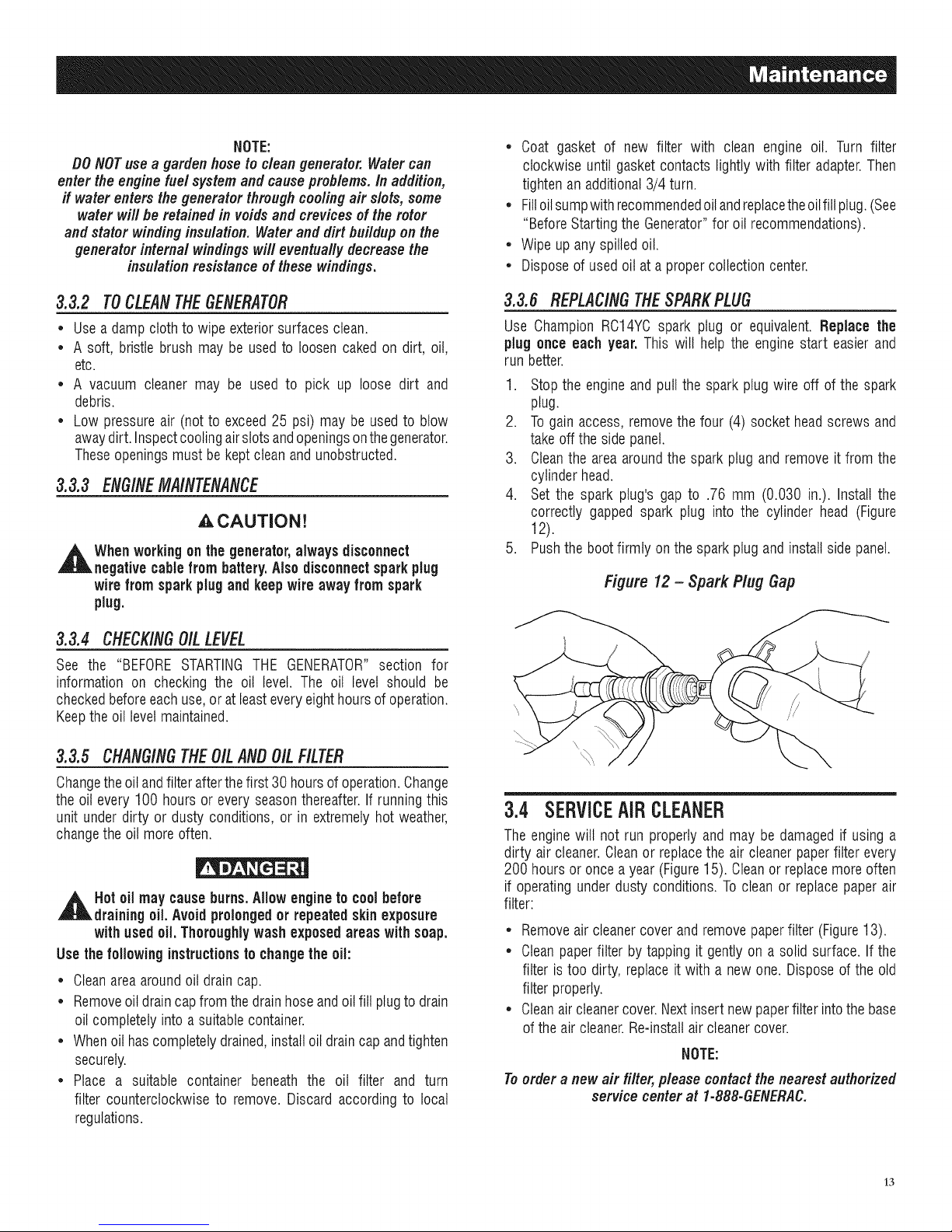
3.3.6 REPLACINGTHESPARKPLUG
Use Champion RC14YCspark plug or equivalent. Replace the
plug once each year. Thiswill helpthe engine start easier and
run better.
1. Stopthe engineand pullthe spark plug wire off of the spark
plug.
2. Togainaccess,removethe four (4) socket head screws and
takeoff theside panel.
3. Cleanthe area aroundthe spark plug and remove it from the
cylinder head.
4. Set the spark plug's gap to .76 mm (0.030 in.). Install the
correctly gapped spark plug into the cylinder head (Figure
12).
5. Pushthe bootfirmly on the sparkplug andinstallsidepanel.
Figure 12 - Spark Plug Gap
3.3.5 CHANG/NGTIlE O/LANOOILFILTER
Changetheoilandfilterafterthe first30hoursof operation.Change
the oilevery 100 hoursor everyseasonthereafter.If runningthis
unit underdirty or dusty conditions, or in extremelyhot weather,
changethe oil moreoften.
,_ Hotoilmay causeburns.Allow engine to coolbefore
draining oil.Avoid prolongedor repeatedskin exposure
with usedoil. Thoroughlywashexposedareaswith soap.
Usethe following instructionsto changethe oil:
• Cleanareaaroundoil draincap.
• Removeoildraincap from the drainhoseandoilfill plugto drain
oil completely intoa suitablecontainer.
• Whenoil has completelydrained,installoil draincapandtighten
securely.
• Place a suitable container beneath the oil filter and turn
filter counterclockwiseto remove. Discardaccordingto local
regulations.
3.4 SERVICEAIRCLEANER
Theenginewill not run properlyand may be damagedif using a
dirty air cleaner.Cleanor replacethe air cleanerpaperfilter every
200 hoursoronceayear (Figure15). Cleanor replacemore often
if operating underdusty conditions.To cleanor replacepaper air
filter:
• Removeair cleanercover andremove paperfilter (Figure13).
• Cleanpaperfilter bytapping it gentlyon a solid surface. If the
filter istoo dirty, replaceit with a new one. Disposeof the old
filter properly.
• Cleanaircleanercover.Nextinsert new paperfilter intothebase
of theair cleaner.Re-installair cleaner cover.
NOTE:
Toorder anew air filter,please contact the nearestauthorized
service center at 1-888-GENERAC.
13
Page 16
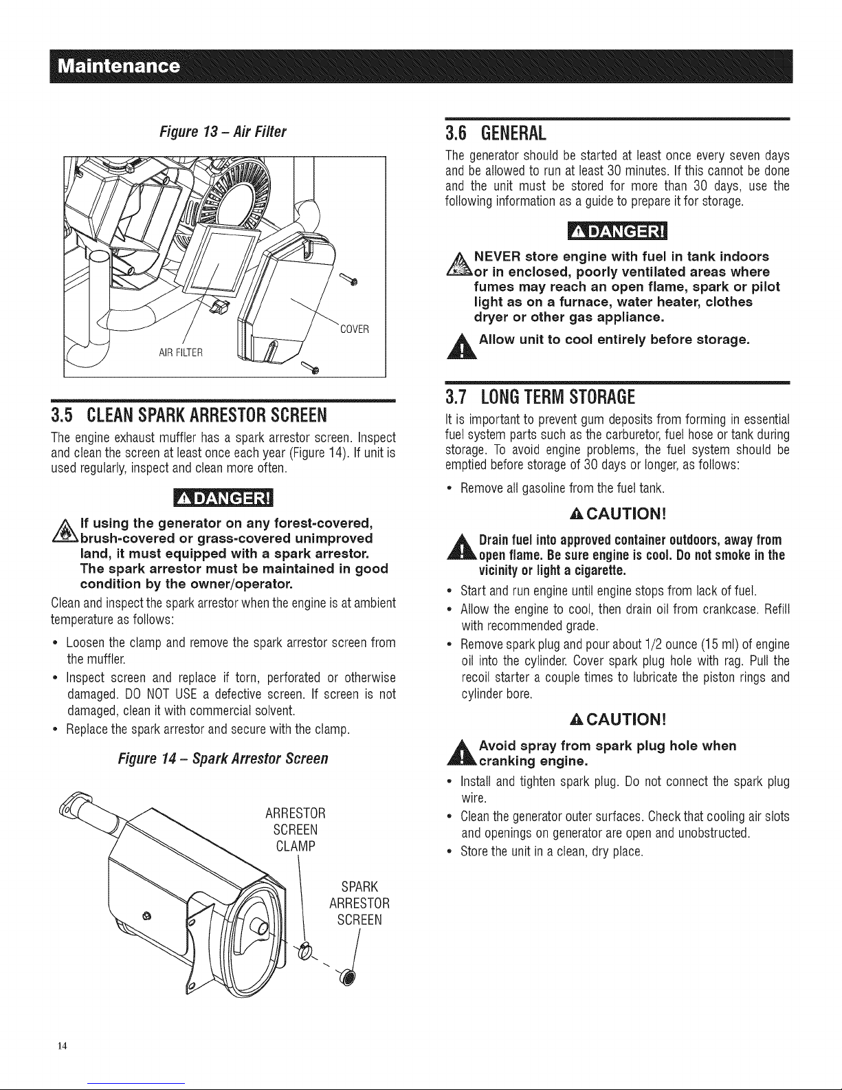
Figure 13- Air Filter
3.6 GENERAL
The generatorshould be started at least once every seven days
andbe allowedto run at least30 minutes.If this cannot be done
and the unit must be stored for more than 30 days, use the
following informationas a guideto prepareit for storage.
NEVER store engine with fuel in tank indoors
or in enclosed, poorly ventilated areas where
fumes may reach an open flame, spark or pilot
light as on a furnace, water heater, clothes
dryer or other gas appliance.
AIRFILTER
3.5 CLEANSPARKARRESTORSCREEN
Theengineexhaustmuffler has a spark arrestor screen. Inspect
and cleanthe screenat leastonceeachyear(Figure14). If unitis
usedregularly,inspectand clean moreoften.
i_lf using the generator on any forest=covered,
brush=covered or grass=covered unimproved
land, it must equipped with a spark arrestor.
The spark arrestor must be maintained in good
condition by the owner/operator.
Cleanandinspectthesparkarrestorwhentheengineis atambient
temperatureas follows:
* Loosenthe clamp and removethe spark arrestor screenfrom
the muffler.
* Inspect screen and replace if torn, perforated or otherwise
damaged. DO NOTUSEa defective screen. If screen is not
damaged,cleanit with commercialsolvent.
* Replacethe sparkarrestorand securewith the clamp.
Figure 14 - Spark Arrestor Screen
ARRESTOR
SCREEN
CLAMP
,l_AIIow unit to cool entirely before storage.
3.7 LONGTERMSTORAGE
It is importantto preventgum depositsfrom forming in essential
fuel system parts such as the carburetor,fuel hoseortank during
storage. To avoid engine problems, the fuel system should be
emptiedbeforestorageof 30 days or longer,asfollows:
* Removeall gasolinefrom thefueltank.
_,CAUTION!
,l& Drainfuel intoapprovedcontaineroutdoors,away from
openflame. Besure engineisc00i. Donotsmokein the
vicinityor lighta cigarette.
* Start andrun engineuntilenginestopsfrom lack of fuel.
* Allow the engineto cool, then drainoil from crankcase.Refill
with recommendedgrade.
* Removesparkplugand pourabout1/2 ounce(15ml) of engine
oil into the cylinder. Cover spark plug hole with rag. Pull the
recoil starter a couple times to lubricatethe piston rings and
cylinder bore.
A CAUTION!
,l_Avoid spray from spark plug hole when
cranking engine.
* Install and tighten spark plug. Do not connect the spark plug
wire.
* Cleanthegeneratoroutersurfaces.Checkthat coolingair slots
and openingson generatorareopenandunobstructed.
* Storethe unitina clean,dry place.
14
ARRESTOR
SPARK
SCREEN
Page 17
3.8 OTHERSTORAGETiPS
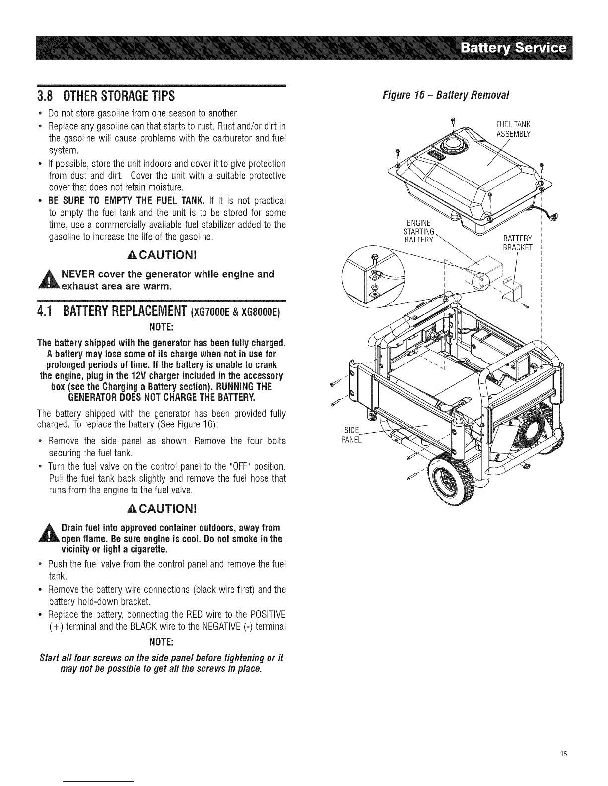
Figure16- Battery Removal
• Do notstore gasolinefrom one seasonto another.
• Replaceanygasolinecanthatstarts to rust. Rust and/ordirt in
the gasolinewill cause problems with the carburetor and fuel
system.
• If possible,storethe unit indoorsandcoverit to give protection
from dust and dirt. Cover the unit with a suitable protective
coverthat doesnot retainmoisture.
• BE SURETO EMPTYTHE FUELTANK. If it is not practical
to empty the fuel tank and the unit is to be stored for some
time, use a commercially availablefuel stabilizeraddedto the
gasolineto increasethe lifeof thegasoline.
,A CAUTION!
,_ NEVER cover the generator while engine and
exhaust area are warm,
4.1 BATTERYREPLACEMENT(XG7000E&XGS000E)
NOTE:
The batteryshippedwiththe generatorhasbeenfully charged.
Abatterymay losesomeof itschargewhennot in use for
prolongedperiodsof time.If the batteryisunableto crank
the engine,pluginthe 12V chargerincludedinthe accessory
box(see the Charging a Batterysection).RUNNINGTHE
GENERATORDOESNOTCHARGETHEBATTERY.
if
ENGINE
STARTIN(
BATTERY
1_ FUELTANK
ASSEMBLY
BATTERY
BRACKET
The battery shipped with the generator has been providedfully
charged.Toreplacethebattery (SeeFigure16):
• Remove the side panel as shown. Remove the four bolts
securingthefueltank.
• Turnthe fuel valve on the control panelto the "OFF"position.
Pull the fuel tank backslightly and removethe fuel hosethat
runs fromthe engineto thefuel valve.
_CAUTION!
,_ Drainfuel intoapprovedcontaineroutdoors,awayfrom
open flame. Besureengineis cool.Donot smokein the
vicinityor lighta cigarette.
• Pushthefuel valvefrom the control paneland removethe fuel
tank.
• Removethe batterywire connections(blackwirefirst) and the
batteryhold-down bracket.
• Replacethe battery,connectingthe REDwire to the POSITIVE
(+) terminal andthe BLACKwire to the NEGATIVE(-) terminal
NOTE:
Start aft four screws onthe side panel beforetighteningor it
may notbe possible toget all the screws in place.
SIDE
PANEL
15
Page 18
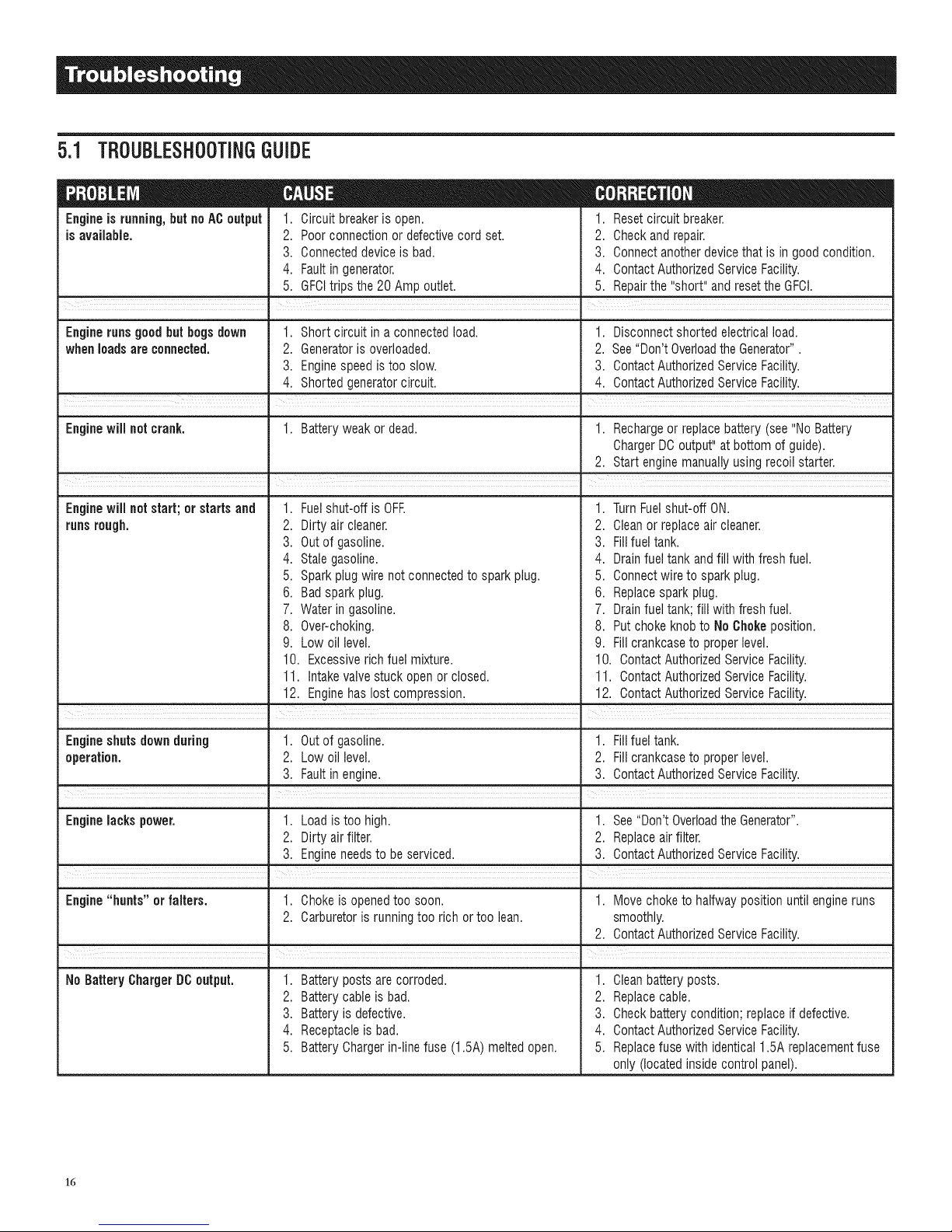
5.1 TBOUBLESHOOTINGGUIDE
Engineis running,but noAC output
is available.
1. Circuit breakeris open.
2. Poorconnection or defectivecord set.
3. Connecteddevice is bad.
4. Fault in generator.
5. GFCItrips the 20 Amp outlet.
. =
1. Resetcircuit breaker.
2. Check and repair.
3. Connect anotherdevicethat is in good condition.
4. ContactAuthorizedServiceFacility.
5. Repairthe "short" andresetthe GFCI.
I
Engineruns good but begs down 1. Short circuit ina connectedload. 1. Disconnect shortedelectricalload.
whenloads are connected. 2. Generatoris overloaded. 2. See"Don't Overloadthe Generator".
3. Enginespeedistoo slow. 3. ContactAuthorizedServiceFacility.
4. Shorted generatorcircuit. 4. ContactAuthorizedServiceFacility.
Enginewill not crank. 1. Batteryweak or dead. 1. Rechargeor replacebattery (see"No Battery
ChargerDCoutput"atbottom of guide).
2. Start enginemanuallyusing recoil starter.
,
Enginewiil not start; or starts and
runsrough.
Fuelshut-off is OFE 1.
2.
Dirty air cleaner. 2.
3.
Outof gasoline. 3.
4.
Stale gasoline. 4.
5.
Sparkplug wire not connectedto sparkplug. 5.
6.
Bad sparkplug. 6.
7. Water in gasoline.
8. Over-choking.
9. Low oil level.
10. Excessiverich fuel mixture.
11. Intakevalvestuck open orclosed.
12. Enginehas lost compression.
i i
TurnFuelshut-off ON.
Cleanor replaceair cleaner.
Fillfuel tank.
Drainfuel tank andfill with fresh fuel.
Connectwire to spark plug.
Replacespark plug.
7. Drainfuel tank;fill with fresh fuel.
8. Put chokeknobto No Chokeposition.
9. Fill crankcaseto properlevel.
10. ContactAuthorizedService Facility.
11. ContactAuthorizedService Facility.
12. ContactAuthorizedService Facility.
Engineshuts downduring 1. Outof gasoline. 1. Fillfuel tank.
operation. 2. Low oil level. 2. Fill crankcaseto properlevel.
3. Fault in engine. 3. ContactAuthorizedService Facility.
I
Enginelacks power. 1. Load is toohigh. 1. See"Don't OverloadtheGenerator".
2. Dirty air filter. 2. Replaceairfilter.
3. Engineneedsto beserviced. 3. ContactAuthorizedService Facility.
Engine"hunts" or falters. 1. Chokeis openedtoo soon. 1. Movechoke to halfwaypositionuntil engineruns
2. Carburetoris runningtoo rich ortoo lean. smoothly.
2. ContactAuthorizedServiceFacility.
NoBatteryChargerDOoutput. 1. Batteryposts arecorroded.
2. Battery cable is bad.
3. Battery is defective.
4. Receptacleis bad.
5. Battery Chargerin-line fuse (1.5A) meltedopen.
1. Cleanbattery posts.
2. Replacecable.
3. Check batterycondition;replaceif defective.
4. ContactAuthorizedServiceFacility.
5. Replacefuse with identical 1.5A replacementfuse
only (located insidecontrol panel).
16
Page 19

17
Page 20
CALIFORNIA AND FEDERAL EMISSION CONTROL WARRANTY STATEMENT
YOUR WARRANTY RIGHTS AND OBLIGATIONS
The California Air Resources Board (CARB) and the United States Environmental Protection Agency (EPA), together with Generac
Power Systems, Inc. (Generac), are pleased to explain the Emission Control System warranty on your new 2008 and later
generator. New equipment that use small spark-ignited engines must be designed, built, and equipped to meet stringent anti-
smog standards for the state of California and the federal government. Generac will warrant the emission control system on your
generator for the period of time listed below provided there has been no abuse, neglect, unapproved modification or improper
maintenance of your equipment.
Your emission control system may include parts such as the: carburetor, ignition system, catalytic converter, fuel tank, fuel lines,
fuel cap, valves, carbon canister, filters, vapor hoses, clamps, connectors, and other associated emission-related components (if
equipped).
MANUFACTURER'S WARRANTY COVERAGE:
This emission control system is warranted for two years. If, during such warranty period, any emission-related part on your
equipment is found to be defective in materials or workmanship, repairs or replacement will be performed by a Generac Authorized
Warranty Service Dealer.
OWNER'S WARRANTY RESPONSIBILITIES:
As the generator owner, you are responsible for the completion of all required maintenance as listed in your factory supplied
Owner's Manual. For warranty purposes, Generac recommends that you retain all receipts covering maintenance on your
generator, but Generac cannot deny warranty solely due to the lack of receipts.
As the generator owner, you should be aware that Generac may deny any and/or all warranty coverage or responsibility if your
generator, or a part/component thereof, has failed due to abuse, neglect, improper maintenance or unapproved modifications, or
the use of counterfeit and/or "grey market" parts not made, supplied or approved by Generac.
You are responsible for contacting a Generac Authorized Warranty Dealer as soon as a problem occurs. The warranty
repairs should be completed in a reasonable amount of time, not to exceed 30 days,
Warranty service can be arranged by contacting either your selling dealer or a Generac Authorized Warranty Service Dealer. To
locate the Generac Authorized Warranty Service Dealer nearest you, call our toll free number:
1=800=333=1322
IMPORTANT NOTE: This warranty statement explains your rights and obligations under the Emission Control System Warranty
(ECS Warranty), which is provided to you by Generac pursuant to California and federal law. See also the "Generac Limited
Warranties for Generac Power Systems, Inc.," which is enclosed herewith on a separate sheet, also provided to you by Generac.
Note that this warranty shall not apply to any incidental, consequential or indirect damages caused by defects in materials or
workmanship or any delay in repair or replacement of the defective part(s). This warranty is in place of all other warranties,
expressed or implied. Specifically, Generac makes no other warranties as to the merchantability or fitness for a particular purpose.
Some states do not allow limitations on how long an implied warranty lasts, so the above limitation may not apply to you.
The ECS Warranty applies only to the emission control system of your new equipment. Ifthere is any conflict in terms between
the ECS Warranty and the Generac Warranty, the Generac Warranty shall apply. Both the ECS Warranty and the Generac Warranty
describe important rights and obligations with respect to your new engine.
Warranty service can be performed only by a Generac Authorized Warranty Service Facility. When requesting warranty service,
evidence must be presented showing the date of the sate to the original purchaser/owner.
If you have any questions regarding your warranty rights and responsibilities, you should contact Generac at the following address:
ATTENTION WARRANTY DEPARTMENT
GENERAC POWER SYSTEMS, INC.
RO. BOX 297 ', WHITEWATER, WI 53190
Part 1
PartNo. 0H1913Rev.A 01/09
18
Page 21
EMiSSiON CONTROL SYSTEM WARRANTY
Emission Control System Warranty (ECS warranty) for equipment using small spark-ignited engines:
(a) Applicability: This warranty shall apply to equipment that uses small off-road engines. The ECS Warranty period shall begin
on the date the new equipment is purchased by/delivered to its original, end-use purchaser/owner and shall continue for 24
consecutive months thereafter.
(b) General Emissions Warranty Coverage: Generac warrants to the original, end-use purchaser/owner of the new engine or
equipment and to each subsequent purchaser/owner that the ECS when installed was:
(1) Designed, built and equipped so as to conform with all applicable regulations; and
(2) Free from defects in materials and workmanship which cause the failure of a warranted part at any time during the ECS
Warranty Period.
(c) The warranty on emissions-related parts will be interpreted as follows:
(1) Any warranted part that is not scheduled for replacement as required maintenance in the Owner's Manual shall be
warranted for the ECS Warranty Period. If any such part fails during the ECS Warranty Period, it shall be repaired or
replaced by Generac according to Subsection (4) below. Any such part repaired or replaced under the ECS Warranty shall
be warranted for the remainder of the ECS Warranty Period.
(2) Any warranted part that is scheduled only for regular inspection as specified in the Owner's Manual shall be warranted
for the ECS Warranty Period. A statement in the Owner's Manual to the effect of "repair or replace as necessary" shall not
reduce the ECS Warranty Period. Any such part repaired or replaced under the ECS Warranty shall be warranted for the
remainder of the ECS Warranty Period.
(3) Any warranted part that is scheduled for replacement as required maintenance in the Owner's Manual shall be warranted
for the period of time prior to first scheduled replacement point for that part. If the part fails prior to the first scheduled
replacement, the part shall be repaired or replaced by Generac according to Subsection (4) below. Any such emissions-
related part repaired or replaced under the ECS warranty shall be warranted for the remainder of the period prior to the first
scheduled replacement point for that part.
(4) Repair or replacement of any warranted, emissions-related part under this ECS Warranty shall be performed at no charge to
the owner at a Generac Authorized Warranty Service Facility.
(5) Notwithstanding the provisions of subsection (4) above, warranty services or repairs must be provided at Generac
Authorized Service Facilities.
(6) When the engine is inspected by a Generac Authorized Warranty Service Facility, the purchaser/owner shall not be held
responsible for diagnostic costs if the repair is deemed warrantable.
(7) Throughout the ECS Warranty Period, Generac shall maintain a supply of warranted emission-related parts sufficient to
meet the expected demand for such parts.
(8) Any Generac authorized and approved emission-related replacement parts may be used in the performance of any ECS
warranty maintenance or repairs and will be provided without charge to the purchaser/owner. Such use shall not reduce
Generac ECS Warranty obligations.
(9) Unapproved, add-on, modified, counterfeit and/or "grey market" parts may not be used to modify or repair a Generac
engine. Such use voids this ECS Warranty and shall be sufficient grounds for disallowing an ECS Warranty claim. Generac
shall not be held liable hereunder for failures of any warranted parts of Generac equipment caused by the use of such an
unapproved, add-on, modified, counterfeit and/or "grey market" part.
EMISSION RELATED PARTS MAY INCLUDE THE FOLLOWING (IF EQUIPPED)"
1) FUEL SYSTEM 3) FUEL METERING SYSTEM
A. FUEL TANK A. CARBURETOR AND INTERNAL PARTS
B. FUEL CAP B. PRESSURE REGULATOR
C. FUEL LINE 4) AIR INDUCTION SYSTEM
D. FUEL LINE FITTINGS A. INTAKE MANIFOLD
E. CLAMPS* B. AIR FILTER
F. PRESSURE RELIEF VALVES* 5) IGNITION SYSTEM
2) EVAPORATIVE CONTROL SYSTEM A. SPARK PLUGS
A. CARBON CANISTER B. IGNITION COILS / MODULE
B. CANISTER MOUNTING BRACKETS 6) AIR INJECTION SYSTEM
C. CARBURETOR PURGE PORT A. PULSE AIR VALVE
D. CONTROL VALVES* 7) EXHAUST SYSTEM
E. VAPOR HOSES A. CATALYST
F. PURGE VALVES B. THERMAL REACTOR
G. LIQUID / VAPOR SEPARATOR C. EXHAUST MANIFOLD
H. VACUUM CONTROL DIAPHRAGMS*
*NOTE: As they relate to the Emission Control System.
Part 2
PartN0.0H1913 Rev.A 01/09
19
Page 22

GENERAC POWER SYSTEMS "TWO YEAR" LiMiTED WARRANTY FOR
XG SERIES PORTABLE GENERATORS
For a period of two years from the dateof original sale, GeneracPower Systems, Inc. (Generac)warrants its XG Series generators will be free from defects in materials
and workmanship for the items and period set forth below. Generac will, at its option, repair or replace any part which, upon examination, inspection and testing by
Generacor a Generac AuthorizedWarranty Service Dealer, is found to be defective.Any equipmentthat the purchaser/owner claims to be defective must be returnedto
and examined by the nearest Generac AuthorizedWarranty Service Dealer.All transportation costs under the warranty, including return to the factory, areto be borne and
prepaid by the purchaser/owner. This warranty applies only to GeneracXG Series portable generators and is not transferable from original purchaser. Saveyour proof-of-
_urchasereceipt. If youdo not provide proof of the initial purchase date, the manufacturer's shipping date of the product will be used to determine the warranty period.
WARRANTY SCHEDULE
;onsumerapplicationsarewarrantedfortwo (2)years.CommercialandRentalapplicationsarewarrantedfor one(1) yearor 1000hoursmaximum,whichevercomes
first.
CONSUMER APPLiCATiON
YEARONE- 100%(onehundredpercent)coverageonLaborandPart(s)(proofofpurchaseandmaintenanceis required):
, AllComponents
YEARTWO- 100%(onehundredpercent)coverageonPart(s)(proofof purchaseandmaintenanceisrequired):
, AllComponents
COMMERCiAL/RENTAL APPLiCATiON
YEARONE- 100%(onehundredpercent)coverageon LaborandPart(s)(proofofpurchaseandmaintenanceis required):
,AllComponents
NOTE: Forthe purpose ofthis warranty "consumer use" means personal residential household or recreational use by original purchaser. This warranty does not apply
to units usedfor Prime Power in place of utility where utility power service is present or where utility power service does not normally exist. Once agenerator
has experienced commercial or rental use, it shall thereafter be considered a non-consumer use generator for the purpose ofthis warranty.
All warranty expenseallowances are subject to the conditions defined inGenerac's Warranty Policies, Procedures and FlatRate Manual.
THiS WARRANTY SHALL NOT APPLY TO THE FOLLOWING:
Generacportable generators that utilize non-Generac replacement parts.
Costs of normal maintenance and adjustments.
Failurescaused by any contaminated fuels, oils or lack of proper oil levels.
Repairs or diagnostics performed by individuals other than Guardian/Generacauthorized dealers not authorized inwriting by GeneracPower Systems.
Failuresdue, butnot limited, to normal wear andtear, accident, misuse, abuse, negligence or improper use.As with all mechanical devices, the Generacengines need
periodic part(s) service and replacementto perform as designed. This warranty will not cover repairwhen normal use has exhaustedthe life of a part(s) or engine.
Failurescaused by any act of God and otherforce majeure eventsbeyond the manufactures control.
Damage relatedto rodent and/or insect infestation.
Productsthat aremodified or altered ina manner not authorizedby Generacin writing.
Any incidental, consequential or indirect damagescaused by defects in materials or workmanship, or any delay in repair or replacement of the defective part(s).
Failuredue to misapplication.
Telephone,cellular phone, facsimile, internet access or other communication expenses.
Living or travel expensesof person(s) performing service, except as specifically included within theterms of a specific unit warranty period.
Expensesrelatedto "customer instruction" or troubleshooting where no manufacturing defect is found.
Rentalequipment used while warranty repairs arebeing performed.
Overnight freight or special shipping costs for replacement part(s).
Overtime, holiday or emergency labor.
Starting batteries,fuses, filters, light bulbs and engine fluids.
HISWARRANTYISINPLACEOFALLOTHERWARRANTIES,EXPRESSEDORIMPLIED,SPECIFICALLY,GENERACPOWERSYSTEMSMAKESNOOTHERWARRANTIES
ASTOTHEMERCHANTABILITYORFITNESSFORAPARTICULARPURPOSE.Anyimpliedwarrantieswhichareallowedby law,shallbelimitedin durationto theterms
oftheexpresswarrantyprovidedherein.Somestatesdonot allowlimitationson howlonganimpliedwarrantylasts,sotheabovelimitationmaynotapplyto purchaser/
owner.
GENERACPOWERSYSTEMSONLYLIABILITYSHALLBETHEREPAIRORREPLACEMENTOFPART(S)ASSTATEDABOVE.INNOEVENTSHALLGENERACPOWER
SYSTEMSBELIABLEFORANYINCIDENTAL,ORCONSEQUENTIALDAMAGES,EVENIFSUCHDAMAGESAREA DIRECTRESULTOFGENERACPOWERSYSTEMS,
INC.NEGLIGENCE.Somestatesdonotallowtheexclusionorlimitationofincidentalor consequentialdamages,sotheabovelimitationsmaynotapplyto purchaser/
owner.Purchaser/owneragreesto makenoclaimsagainstGeneracPowerSystems,Inc.basedon negligence.Thiswarrantygivespurchaser/ownerspecificlegalrights.
Purchaser/owneralsomayhaveotherrightsthatvaryfromstateto state.
GENERAC POWER SYSTEMS, INC.
P.O. BOX 8 " Waukesha, Wl 53187
Ph: (888) GENERAC (438-3722) • Fax: (282) 544-4851
To locate the nearest Authorized Dealer visit our website www.generac.com
PartNo.0H5472 RevisionB (10/20/09) PrintedinU.S.A.
Manual PartNo. 0H3530 RevisionE (09/30/10) Printedin U.S.A.
Page 23
MODELO:
005796-0(×G6500),005797-0(×GTO00),
005798-0 (XG7OOOE),005800-0 (×GSO00),
005747-0 (XG8OOOE)
[]
XGSeriesGeneradorportatilde6,500-8,
OS
Page 24
Introduccion............................................................1
Leaestemanualcornpletamente............................1
Reglasde seguddad...............................................1
indicedeestandares......................................................3
InforrnacionGeneral...............................................4
1.1 Uesempaque..................................................................4
1.1.1 Cajade accesorios............................................4
1.2 Ensamble.......................................................................4
1.2.1 Ensamblajede larueda......................................4
Operation ...............................................................5
2.1 Conociendoel generador................................................5
2.1.1 Conexionde la bateria........................................6
2.2 Medidorde horas...........................................................6
2.3 Juegodecablesy conectores........................................6
2.3.1 Recept_,culoduplexde 120 VAC, 20 Amp.......6
2.3.4 Receptaculode 120/240 VAC,30 Amp..............6
2.4 Como usarestegenerador.............................................7
2.4.1 Tierradelsistema..............................................7
2.4.2 Conexi6natierra del generador..........................7
2.4.3 Conexiona tierradet neutroal marcos ...............8
2.4.4 Conexionde las cargosel_ctricas......................8
2.5 Nosobrecargueetgenerador..........................................8
2.6 Guiade refrenciade potencias.......................................8
2.7 Antes de arrancaretgenerador.......................................9
2.7.1 Agregaraceitede motor.....................................9
2.7.2 A_adirgasolina..................................................9
2.8 Arranquedelmotor ......................................................10
2.8.1 Arranquemanual(recule).................................10
2.8.2 Arranqueetectrico(XG7000E& SG8000E).......10
2.9 Deteneretmotor..........................................................10
2.10 Sistemade apagadoporbajapresionde aceite............11
2.10.1 Reiniciar..........................................................11
2.11 Cargade la bateria.......................................................11
iVlantenimiento......................................................11
3.1 Cronogramade mantenimiento..................................... 11
3.2 Especificacionesdel producto......................................11
3.2.1 Especificacionesdelgenerador........................11
3.2.2 Especificacionesdetmotor ..............................12
3.2.3 Informacionsobre emisiones........................... 12
3.3 Recomendacionesgenerales........................................12
3.3.1 Mantenimientodelgenerador...........................12
3.3.2 ParaLimpiarelgenerador................................12
3.3.3 Mantenimientodelmotor.................................12
3.3.4 Revisaret nivetde aceite..................................13
3.3.5 Cambiode aceitey filtro de aceite...................13
3.3.6 Reemptazode labujia......................................13
3.4 Darservicio al limpiador de aire...................................13
3.5 Limpiar pantalladet supresorde chispa........................13
3.6 General........................................................................14
3.7 Almacenamientoa largoplazo......................................14
3.8 Otrosconsejos paraalmacenamiento...........................14
Servicio a la bateria.............................................15
4.1 Reemplazodelabateria(XG7000E& XG8000E)..........15
Deteccionde problemas.......................................16
5.1 Guiade deteccionde problemas..................................16
Notas....................................................................17
Garantia................................................................18
ADVERTENCIA DELA PROPOSICION65 DE CALIFORNIA
El Estadode California sabeque el escapedel motory
algunos de suscomponentescausancancer,defectos de
nacimientoy otros da_osreproductivos.
ADVERTENCIA DE LA PROPOSICION55 DE CALiFORNiA
Esteproductocontieneo emite quimicos que el Estadode
California sabe quecausancancer,defectos denacimiento u
otros da_os reproductivos.
Page 25
INTRODUCCION
Gracias por comprar este modelo de Generac Power Systems, Inc.
Estemodelo es un generadorimpulsado por motor,refrigerado por aire,
compacto y de alto rendimiento disehado para proporcionar energia
electricaparaoperarcargas electricasdondeno haya servicio publico de
electricidado en reemplazode la red electricaencaso de apagones.
LEAESTEMANUALCOIV1PLETAMENTE
Si alguna parte de este manual no se entiende bien, pongase en
contacto con el concesionario autorizadomas cercanopara conocer los
procedimientosde arranque,operaciony servicio.
El operadores responsabledel uso apropiadoy seguro de este equipo.
Recomendamos encarecidamenteque el operador lea este manual y
entienda completamente todas las instrucciones antes de usar este
equipo. Asimismo recomendamos con igual firmeza el instruir a otros
usuarios para arrancar y operar apropiadamente la unidad. Esto los
preparasi necesitanoperar el equipoen algunaemergencia.
El generadorpuedeoperar en forma segura, eficientey confiable solo si
sele ubica,se le opera y mantieneenforma apropiada.Antesde operar
o darservicio al generador:
* Familiaricese y adhierase estrictamente a todos los codigos y
regulacioneslocales,estatalesy nacionales.
, Estudietodas las advertencias de seguridaden este manual yen el
producto con mucho cuidado.
* Familiaricesecon estemanualy la unidad antes deusarla.
El fabricante no puede anticipar todas las posibles circunstancias
que puedan involucrar peligros. Las advertencias en este manual y
en las etiquetas y calcomanias fijadas en la unidad son, por tanto, no
completamenteinclusivas. Sise usaun procedimiento,metododetrabajo
otecnica deoperacionqueelfabricantenorecomiendaespecificamente,
aseguresede quesea seguropara los demas.Asimismo asegureseque
el procedimiento,metodo de trabajo o tecnica de operacion utilizadano
vuelva inseguroal generador.
LA INFORMACIONCONTENIDAAQU[ SE BASO EN MAQUINASEN
PRODUCCIONAL MOMENTODE LA PUBLICACION.GENERACSE
RESERVAEL DERECHODE MODtFICARESTEMANUALENCUALQUIER
MOMENTO.
BEGLASDESEGUBIDAD
A Io largo de esta publicacion, yen Io que respecta a las etiquetas
y calcomanias fijadas en el generador, los bloques de PELtGRO,
ADVERTENCIA,CUIDADOY NOTAseusan para alertaral personalsobre
instruccionesespecialessobreuna operacionenparticular quepuedeser
peligrosasi seejecutaenforma incorrectao sincuidado.Observelascon
cuidado. Susdefinicionesson como sigue:
INDICAUNASITUACIONPELiGROSA0 ACCI()NQUE,SI NOSEEVITA,
TRAERACOIVIORESULTADOLAIVIUERTEO UNDANGSERIO.
Indicaunasituaci6npeligrosaoacci6nque,si nose evita,podria
traercomeresultadola muerteounda_oserio.
A,C UIDADO
Indicaunasituaci6n peligrosao acci6nque, si no se evita, puede
traer comeresultado un da_omenor omoderado.
NOTA:
Las notas contienen informacion adicional impertante para un
procedimiento y se les encontrara dentro de/cuerpo de este manual
Estas advertencias de seguridad no pueden eliminar los peligros que
indican.Elsentido comuny un estricto cumplimientode lasinstrucciones
especialescuando se realizala accion o servicio son esenciales para
evitaraccidentes.
Ouatro simbolos de seguridad usados comunmente acompahan los
bloquesde PELIGRO,ADVERTENCIAy CUIDADO.Eltipo de informacion
quecadaunoindicaes como sigue:
,_ Este simbolo serbia impertante informaci6ndeseguridad que,
si no se sigue, puedeporteren peligrola seguridad personal
y/o las propiedadesde otros.
Estesimbolo indicaunpeligropotencialde explosi6n.
i/_Este simbolo indicaunpeligropotencialde incendio.
//_kEste simbolo indicaun peligropotencialde chequeelectrico.
PELIGBOSGENEBALES
* Nuncaopereenareas cerradaso interiores.
* Porrazonesdeseguridad,elfabricanterecomiendaqueelmantenimiento
de este equipo sea Ilevadoa cabo por un concesionario autorizado.
Inspeccione el generador con regularidad, y pongase en contacto
con el concesionario autorizadomD.scercanosi necesitarepararloo
conseguirrepuestos
* Opere el generador solo en superficies planas y donde no este
expuestoa excesivahumedad,suciedad, polvo ovaporescorrosivos.
* Mantengalas manos, pies, ropa, etc, lejosde lascorreasde traccion,
ventiladoresy otras partes moviles o calientes.Nuncaretireninguna
proteccionde ventiladormientrasla unida esteoperando.
* Algunas partes de este generadorse calientan mucho durante la
operacion. Mantenga distancia del generador hasta que se haya
enfriadoparaevitar quemadurasseveras.
* NOopereel generadoren laIluvia.
* No altere la construccion del generadorni cambie los controles de
modo que puedancrear una condicion deoperacionno segura.
* Nuncaarranqueo detengalaunidadcon cargas electricasconectadas
alas tomasY con dispositivosconectadosy encendidos.Arranqueel
motory deje quese estabiliceantesde conectarlas cargaselectricas.
Desconectetodas las cargaselectricas antesde apagar elgenerador
* No inserte objetos a traves de las ranuras de enfriamiento de la
unidad.
* AI trabajar con este equipo, mantengase alerta en todo momento.
Nunca trabaje en el equipo cuando este fisica o mentalmente
fatigado.
* .Nunca use el generador ni alguna de sus partes como escal6n.
Pararsesobre la unidadpuedetensar y romper partes, y puedetraer
comoresultadocondiciones peligrosasdeoperacioncomo escapede
gases,combustibleo aceite.
Page 26
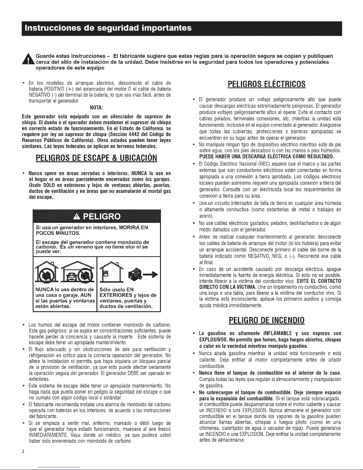
Guarde estas instrucciones - El fabricante sugiere que estas reglas para la operaciCn segura se copien y publiquen
cerca del sitio de instalaciCn de la unidad. Debe insistirse en la seguridad para todos los operadores y potenciales
operadores de este equipo
En los modelos de arranque electrico, desconecte el cable de
bateriaPOSlTIVO(+) del arrancador del motor 0 el cable de bateria
NEGATIVO(-) delterminaldelabateria,IoqueseamD.sfD.cil,antesde
transportar el generador.
NOTA:
Este geuerador est_i equipado con un silenciador de supresor de
chispa. Eldue_o o el operadordebenmantener el supresor de chispa
eu correcto estado de funciouamiento.En el Estado de California, se
requierepot ley un supresor de ¢hispa (Seccicn4442 del Codigode
RecursosP{_blicosde California).0tros estados puedeu tuner leyes
similares. Las leyes federalesse aplicau en terrenos federales.
PELIGROSDEESCAPE& UBICACI0N
Nunca opere en _ireas cerradas o interiores. NUNCAIo use en
el hogar ni eu ;ireas parcialmente encerradas como los garajes.
Uselo SOLOen exteriores y lejos de ventauas abiertas, puertas,
ductosde ventilacicuyen areas que no acumularan el mortal gas
delescape.
Si usa un generador en interiores, MORIRA EN
POCOS MINUTOS.
El escape del generador contiene mon6xido de
carbono. Es un veneno que no tiene olor ni se
puede ver.
NUNCA Io use dentro de
una casa o garaje, AUN
si las puertas y ventanas
estan abiertas.
Solo _selo EN
EXTERIORES y lejos de
ventanas, puertas y
ductos de ventilacion.
PELIGROSELI'CTRICOS
• El generador produce un voltaje peligrosamente alto que puede
causardescargaselectricas extremadamentepeligrosas. Elgenerador
producevoltajes peligrosamentealtos al operar.Eviteel contacto con
cables pelados, terminales conexiones, etc. mientras la unidad esta_
funcionando,inclusiveenel equipoconectadoalgenerador.Asegurese
que todas las cubiertas, protecciones y barreras apropiadas se
encuentrenen su lugar antes deoperar el generador.
• No manipule ningun tipo de dispositivo electrico mientraseste de pie
sobreagua,con lospiesdescalzos ocon las manos o pieshumedos.
PUEDEHABERUNADESCARGAELECTRICAC01Vl0RESULTAD0.
• El Codigo ElectricoNacional (NEC)equiereque el marco y las partes
externasque son conductores electricos esten conectadas enforma
apropiadaa una conexion a tierra aprobada. Los ccdigos electricos
localespuedenasimismo requerirunaapropiadaconexion a tierra del
generador.Consulte con un electricista local los requerimientos de
conexiona tierra para suarea.
• Use un circuito interruptor defalla de tierra en cualquierD.reahumeda
o altamente conductiva (como estanterias de metal o trabajos en
acero).
• No usecables electricosgastados,pelados,deshilachadoso de algun
modo dafiados con el generador.
• Antes de realizar cualquier mantenimientoal generador, desconecte
los cables debateriade arranquedel motor (si los hubiera) paraevitar
un arranqueaccidental. Desconecteprimero el cable del borne de la
bateriaindicado como NEGATIVO,NEG; o (-). Reconecteese cable
al final.
• En caso de un accidente causado por descarga electrica, apague
inmediatamentela fuente de energiaelectrica. Si esto no es posible,
intente liberar a la victima del conductor vivo. EVITEEL OONTAOTO
DIREOTOCONLAViCTIMA. Uneun implementonoconductivo, como
unasoga o una tabla, paraliberar a la victima del conductor vivo. Si
la victima esta inconsciente,aplique los primeros auxilios y consiga
ayudamedicainmediatamente.
• Los humos del escape del motor contienen monoxido de carbono.
Estegaspeligroso, si se aspiraen concentracionessuficientes,puede
hacerle perder la concienciay causarle la muerte. Este sistema de
escapedebetener un apropiadomantenimiento
• El flujo adecuado y sin obstrucciones de aire para ventilaci6n y
refrigeraciones critico para la correcta operaci6n del generador.No
altere la instalacion ni permita que hayasiquiera un bloqueoparcial
de la provisbn de ventilacion, ya que esto puede afectar seriamente
la operacionseguradelgenerador.ElgeneradorDEBEser operadoen
exteriores.
• Este sistema de escapedebetener un apropiado mantenimiento.No
haganadaquepuedaporter en peligrola seguridaddel escape o que
no cumpla con alguncodigo local o estandar.
• Elfabricante recomiendainstalaruna alarma demonoxidode carbono
operadacon bateriasen losinteriores,deacuerdoalas instrucciones
delfabricante.
• Si se empieza a sentir mal, enfermo, mareado o debil luego de
que el generadorhaya estado funcionando, muevaseal aire fresco
INMEDtATAMENTE.Vaya donde un medico, ya que pudiera usted
habersidoenvenenadocon monoxido de carbono.
PELIGR0DEINCENDi0
• La gasolina es altamente INFLAIVIABLEy sus vapores son
EXPLOSIVOS.No permitaquelumen,hagafuegosabiertos, chispas
o calor en la vecindadmientras manipula gasolina.
• Nunca afiada gasolina mientras la unidad esta funcionando o esta
caliente. Deje enfriar al motor completamente antes de ar_adir
combustible.
• Nunca Ilene el tanque de combustibleen el interior de la casa.
Cumplatodas lasleyesque regulanelalmacenamientoymanipulacbn
de gasolina.
• No sebrecargue el tanque de combustible.Deje siempre espacio
para la expansiondel combustible.Sieltanqueesta sobrecargado,
el combustiblepuededesparramarsesobre elmotorcaliente y causar
un INCENDIOouna EXPLOSION.Nunca almacene el generadorcon
combustible en eltanque donde los vapores de la gasolina pueden
alcanzar llamas abiertas, chispas o fuegos piloto (como en una
chimenea,calentador de agua o secador de ropa). Puedegenerarse
unINOENDIOouna EXPLOSION.Dejeenfriarla unidadcompletamente
antesdealmacenarse.
Page 27

* Limpiecualquierderramedecombustibleinmediatamente.Asegurese
dequenosehayadejadomaterialescombustiblessobreocercadel
generador.Mantengaela.reacircundantedelgeneradorlimpiaylibre
deresiduosyconserveunespaciodecinco(5)piesatodosloslados
parapermitirunaventilacionapropiadadelgenerador.
* Noopereelgeneradorsi losdispositivoselectricosconectados
sesobrecalientan,silasalidaelectricasepierde,sielmotoroel
generadorechanchispasosiseobservahumocuandolaunidadesta.
funcionando.
* Tengaunextinguidorcercaalgeneradorentodomomento.
/NB/CEBE ESTANBARES
Enausenciade losestandares,codigos, regulacioneso leyes pertinentes,
la informacion publicada listada abajo puede usarse como guia para
la operacion de este equipo. Siempre consulte la revision mas reciente
aplicablepara el estandarlistado.
1. NFPANo.70, NFPAHANDBOOKOFNATIONALELECTRICCODE.
2. Article X, NATIONALBUILDINGCODE,disponible en la American
InsuranceAssociation,85 John Street, NewYork, N.Y.10038.
3. AGRICULTURALWIRING HANDBOOK,disponible en la Food and
EnergyCouncil, 909 UniversityAvenue,Columbia,MO65201.
4. ASAE EP-3634, INSTALLATIONAND MAINTENANCEOF FARM
STANDBYELECTRICALSYSTEMS,disponibleenla American Society
of AgriculturalEngineers,2950 NilesRoad, St.Joseph, MI49085.
5. NFPANo.30, FLAMMABLEANDCOMBUSTIBLELIQUIDSCODE.
MODELONO:
SERIENO:
Paca de IB de/generador
PLACADE
IDENTIFICACiON
Page 28

1.1 DESEMPAQUE
• Retiretodo elmaterialdeempaque.
• Retirela caja separadade accesorios.
• Retirela caja delgenerador.
1.1.1 CAJADEACCESORiOS
Revisetodo el contenido (figura 1). Si alguna parte no se encuentrao
esta,dafiada,ubiquea un concesionarioautorizadoen el tell 1-888-775-
6937.
El contenidoincluye:
• 2- Pasadoresdel eje • Filtrodel Aceite
• 2- Espaciadoresde rueda • Filtrode aire
• 2- Pasadoresde cabello • Bujia
• 2-Ruedas • Llavede bujias
• 1 - Patadel marco • Toalladetaller
• 2 - Montajes devibracion • 2 - Arandeladel marco
• 2 - Tornillodel marco "• Chimeneadeaceite
• 4-Tuercas de reborde • Conectorcarga adaptadorde 12
VDC
• 2 botellasde 1 cuarto de galonde aceiteSAE30
Figura 1- Cajas de accesorios
NOTA:
El kit de ruedas no esta disefiadopara su uso en las pistas.
• Consultela figura 2 e instaleel juego de rueda y la pata del
marco como sigue:
• Desticeel pasadordelejeatravesdela rueda,etespaciadorde
la rueda (arandela)y etmarco.
• Instaleet pasadorde cabelloal pasadordel ejeparaasegurarla
rueda.Repitaparaet ladoopuesto.
• Asegurelos montajesdevibraciona la pata detmarcocon las
tuercasde cierre incluidas.
• Parainstalar la pata del marco, instale los pernosdet marco a
trav_sde las arandetas,en marco y la pata. Asegurecon las
tuercade reborde.
Figura 2 - Rueda y La Plata Del Marco
DEL MARCO
ABEGURARRUEDA
Y EJECON
PASADOR
DECABELLO
1.2 ENSAMBLE
Lea el manual completo antes de intentar ensamblar u operar el
generador.El generadorrequiere algun ensamble antes de usarse. Si
se presentanproblemas al ensamblarel generador,por favor Ilamea la
Generator Helpline al 1-888-775-6937.
1.2.1 ENSAMBLAJEDE LARUEDA
Elkitde laruedaestadisefiadoparamejorarengranmedidala portabilidad
del generador.Ustednecesitara_las siguientesherramientas parainstalar
el kit de la rueda: Pinzas,Ilavede 1/2" (13mm) y una Ilavede dado con
un dadode 1/2" (13 mm).
ARANDELA
DEL MARCO
TORNILLO
DELMARCO
ESPACIADOR
DERUEDA
(ARANDELA)
DESLICEEL EJEA
TRAVESDELA
RUEDAY ELESPACIADOR
DELA RUEDA
TUERCADE
e___REBORDE
Page 29
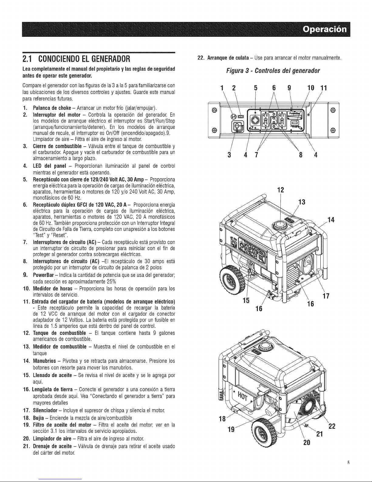
2.1 CONOCiENDOELGENERADOR
Leacompietamenteel manual delpropietarioylas regiasdeseguridad
antes de operarestegenerador.
Compareel generadorcon lasfiguras dela 3 ala 5 parafamiliarizarsecon
las ubicaciones de los diversos controles y ajustes. Guardeeste manual
parareferenciasfuturas.
1. Palanca de choke- Arrancarun motor frio (jalar/empujar).
2. Interruptordel motor - Controla la operacbn del generador.En
los modelos de arranqueelectrico el interruptor es Start!Run/Stop
(arranque/funcionamiento/detener).En los modelos de arranque
manualde recule, el interruptor es On/Off(encendido/apagado).9.
Limpiadorde aire - Filtrael aire de ingresoal motor.
3. Cierrede combustible- Va_lvulaentre el tanque de combustible y
el carburador.Apagueyvacie el carburadorde combustiblepara un
almacenamientoa largopiazo.
4. LED del panel- Proporcionan iluminacbn al panel de control
mientrasel generadoresta,operando.
5. Receptaculoconcierre de120/240 VoltAC,30 Amp- Proporciona
energiaelectricaparalaoperaciondecargasdeiluminacbn electrica,
aparatos,herramientaso motores de 120 y/o 240VoltAC, 30 Amp,
monofasicos de60 Hz.
6. Receptaculo duplex GFCIde 120 VAC,20 A- Proporcionaenergia
electrica para la operacbn de cargas de iluminacbn electrica,
aparatos,herramientaso motores de 120 VAC, 20 A monofasicos
de60 Hz.Tambienproporcionaproteccioncon unlnterruptor Integral
deCircuitode FalladeTierra,completo con unapresionalos botones
"Test" y "Reset".
7. Interruptoresde circuito(AC)- Cadarecepta_cu]oestaprovistocon
un interruptor de circuito de presionar para reiniciar con el fin de
protegeral generadorcontra sobrecargaselectricas.
8. Interruptoresde circuito (AC) -El receptaculo de 30 amps esta.
protegidoporun interruptorde circuito de palancade 2 polos
9. PowerBar-Indica lacantidaddepotenciaque se usadel generador;
cadaseccion esaproximadamente25%
10. Medidor de betas - Proporcionalas horas de operacion para los
intervalos deservicio.
11. Entrada del cargador de bateria (modelos de arranque electrico)
- Este receptaculo permite la capacidad de recargar la bateria
de 12 VCC de arranque del motor con el cargador de conector
adaptadorde 12 Voltios. Labateriaestaprotegidapot un fusible en
lineade 1.5 amperios queesta,dentrodel panelde control.
12. Tanque de combustible - El tanque contiene hasta 9 galones
americanosde combustible.
13. Medidor de combustible- Muestra el nivel de combustible en el
tanque
14. Manubrios - Pivotea y se retracta para almacenarse. Presionelos
botonescon resorte paramover los manubrios.
15. Llenade de aceite - Serevisa el nivel de aceitey se le agregapor
aqui.
16. Lengiieta de tierra - Conecteel generadora una conexbn atierra
aprobadadesde aqui.Yea "Conectandoel generadora tierra" para
mayoresdetalles
17. Silenciador -Incluye elsupresorde chispa y silenciael motor.
18. Bujia - Enciendelamezclade aire/combustible
lg. Filtro de aceite del motor - Filtra el aceite del motor; ver en la
seccion 3.1 los intervalos de servicio apropiados.
28. Limpiader de aire - Filtraelairedeingresoalmotor.
21. Drenaje de aceite - Va.lvulade drenajepara retirarel aceite usado
delca.rterdel motor.
22. Arranque de culata- Usepara arrancarel motor manualmente.
Figura 3 - Controles del generador
1 2 5 6 9 10 11
r
@
@
3 4 7 8 4
12
13
15
17
16
16
18
22
2O
Page 30
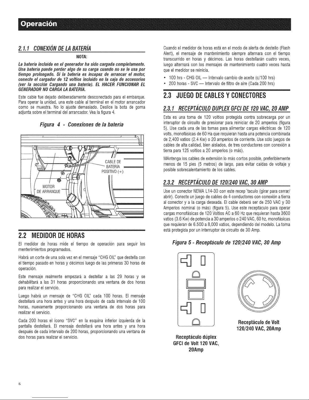
2.1.1CONEXlONDELABATERiA
NOTA:
La bateria incluida en el generador ha sido cargada completamente.
Una bateria puede perder algo de su carga cuando no se le usa por
tiempo prolongado. Si la bateria es incapaz de arrancar el motor,
conecte el cargador de 12 voltios incluidoen la caja de accesorios
(ver la seccion Cargando una bateria). EL HACERFUNClONAREL
GENERADORNOCARGALABATER/A.
Estecable fue dejadodeliberadamentedesconectadopara el embarque.
Paraoperar la unidad, unaeste cable al terminal en elmotor arrancador
como se muestra. No Io ajuste demasiado. Deslice la bota de goma
adjunta sobreel terminal delarrancador.Veala figura 4.
Figura 4 - Conexionesde la bateria
_%\\ _ j,._ __ CABLEDE
_:2_/ / _ ....BATERIA
_' / _ _ POSIT!VO(+)
2.2 MEDIDORDEHORAS
El medidor de horas mide el tiempo de operacbn para seguir los
mentenimientosprogramados.
Habraun corte deuna solavez en el mensaje"OHGOIL:'quedestella con
el tiempo pasadoen horasy decimos luegode las primeras 30 horasde
operacion.
Este mensaje realmente empezara,a destellar a las 29 horas y se
dehabilitaraalas 31 horas proporcionando una ventana de dos horas
para realizarel servicio.
Luego habra un mensaje de "CHG OIL:'cada 100 horas. El mensaje
destellarauna hora antes y una hora despues de cada intervalo de 100
horas, nuevamente proporcionando una ventana de dos horas para
realizarel servicio.
Cuandoel medidor de horas estaen elmodo de alerta de destello (Flash
Alert), el mensaje de mantenimiento siempre alternara con el tiempo
transcurrido en horas y decimos. Las horas destellara.ncuatro veces,
luegoalternaracon los mensajes de mantenimientocuatro veces hasta
queel medidorsereinicia.
• 100hrs - CHGOIL-- Intervalocambio de aceite(c/100 hrs)
• 200horas - SVC-- Intervalo defiltro de aire(Cada200 hrs)
2.3 JUEGODE CABLESY CONECTORES
2.3.1 RECEPT,4CULODUPLEXGFC/DE 120VAC,20 AMP
Esta es una toma de 120 voltios protegida contra sobrecarga por un
interuptor de circuito de presionarparareiniciar de 20 amperios (figura
5). Usecada una de las tomas para alimentarcargas electricas de 120
volts, monofasicasde60 Haque requieranhastauna potenciacombinada
de2,400 vatios (2.4 Kw) o 20 amperios decorriente. Usesolo juegos de
cablesde altacalidad,bien aislados,de tres conductorescon conexbn a
tierra para 125 voltios a 20 amperios (omas).
MAntengalos cablesde extensbn Io mas cortos posible, preferiblemente
menDsde 15 pies (5 metros) de largo, para evitar caidas de voltaje y
posiblesobrecalentamientodelos cables.
2.3.2 RECEPTACULODE 120/240VAC,30 AMP
Useun conector NEMAL14-30 con este recep'taculo (girarpara cerrar/
abrir).Conecteunjuegode cablesde 4 conductores conconexionatierra
al conector y a la carga deseada.Elcabledeberaser de 250 VAC y 30
Amperios nominal (o mas) (figura 5). Useeste receptaculopara operar
cargasmonofasicasde 120VoltiosAC a60 Hzque requieranhasta3600
vatios (3.6 Kw)depotenciaa 30amperioso240 VAC,60 hz,monofasicas
querequierande 6.500 a 8,000 vatios, dependiendodel modelo. Latoma
esta.protegidapor un interruptorde circuitode 30 Amp.
Figura 5 - Receptaculo de 120/240 VAC, 30 Amp
Cada 200 horas el icono "SVC" en la esquina inferior izquierda de la
pantalla destellara. El mensaje destellara,una hora antes y una hora
despues decada intervalo de200 horas, proporcionandouna ventanade
dos horaspara realizarel servicio.
Receptaculo de Volt
120/240 VAC,20Amp
Receptaculo duplex
GFCIde Volt 120 VAC,
20Amp
Page 31
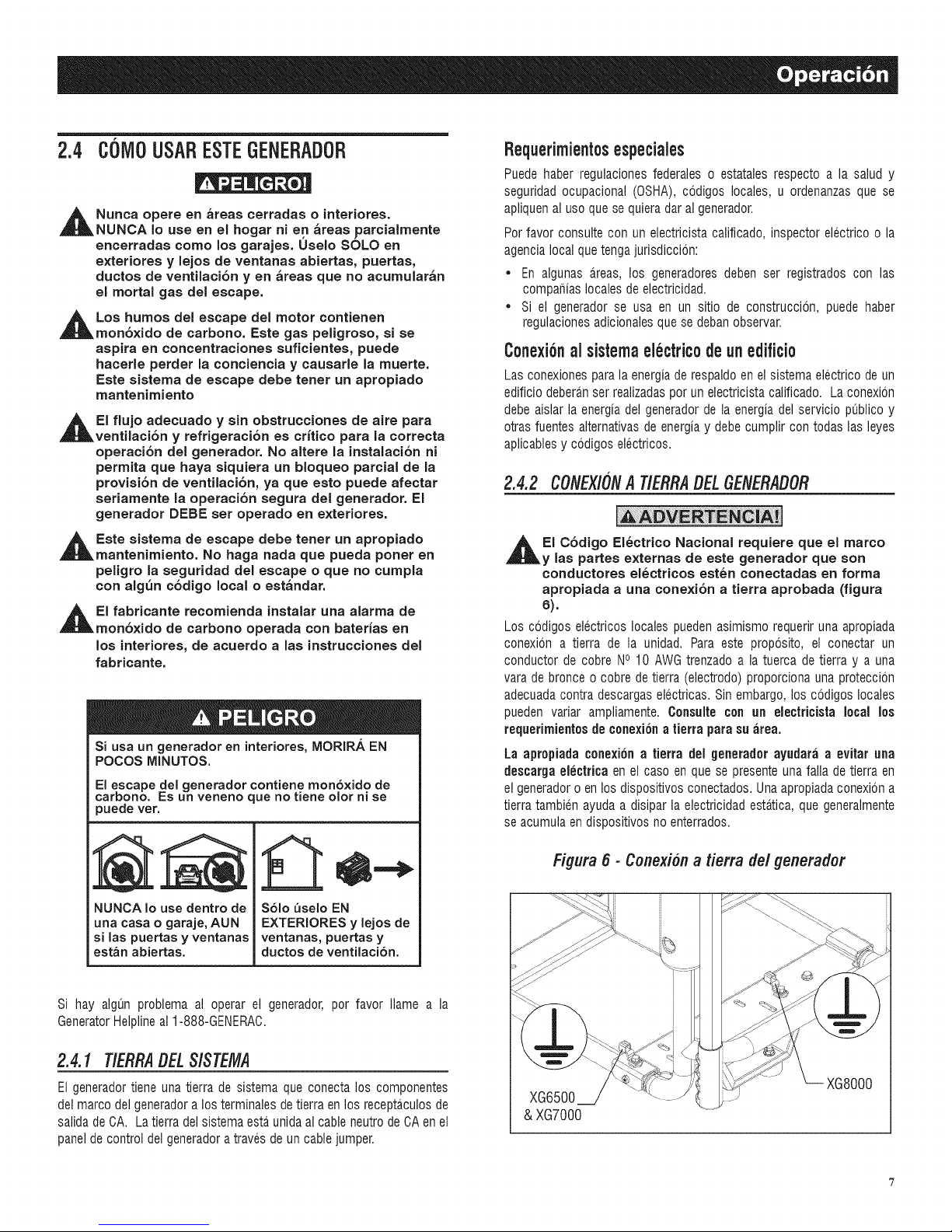
2.4 C6MOUSARESTE6ENERADOR
,_ Nunca opere en _reas cetradas o interiotes.
NUNCA Io use en el hogar ni en _reas parcialmente
encerradas come los garajes. Uselo SOLO en
exteriores y lejos de ventanas abiertas, puertas,
ductos de ventilaci6n y en _reas que no acumular_n
el mortal gas del escape.
,_Los humos del escape del motor contienen
mon6xido de carbono. Este gas peligroso, si se
aspira en concentraciones suficientes, puede
hacerle perder la conciencia y causarle la muerte.
Este sistema de escape debe tenet un apropiado
mantenimiento
,_EI flujo adecuado y sin obstrucciones de aire para
ventilaci6n y refrigeraci6n es crftico para la correcta
operaci6n del generador. No altere la instalaci6n ni
permita que haya siquiera un bloqueo parcial de la
provisi6n de ventilaci6n, ya que esto puede afectar
seriamente la operaci6n segura del generador. El
generador DEBE set operado en exteriores.
,_ Este sistema de escape debe tenet un aptopiado
mantenimiento. No haga nada que pueda poner en
peligro la seguridad del escape o que no cumpla
con alg_n c6digo local o est_ndar.
,_EI fabricante recomienda instalar una alarma de
mon6xido de carbono operada con baterfas en
los interiores, de acuerdo alas instrucciones del
fabricante.
Si usa un generador en interiotes, MORIRA EN
POCOS MINUTES.
El escape del generador contiene mon6×ido de
carbono. Es un veneno que no tiene olor ni se
puede vet.
Requerimient0sespeciales
Puede haber regulacionesfederales o estatales respecto a la salud y
seguridad ocupacional (OSHA),codigos locales, u ordenanzasque se
apliquenal use que se quieradar al generador.
Perfavor consultecon un electricistacalificado, inspector electrico o la
agencialocal quetengajurisdiccion:
* En algunas areas, los generadoresdeben ser registrados con las
compafiias localesde electricidad.
* Si el generador se usa en un sitio de construccion, puede haber
regulacionesadicionalesque se debanobservar.
C0nexi6nal sistemaelectric0deunedifici0
Las conexionesparala energiade respaldoen el sistema electrico de un
edificio deberanser realizadasper un electricistacalificado. Laconexion
debe aislar la energiadel generadorde la energiadel servicio publico y
otras fuentes alternativasde energiay debe cumplir con todas las leyes
aplicablesy codigos electricos.
2.4.2 CONEXlONATIERRADELGENERADOR
,i_EI C6digo EI6ctrico Nacional requiere que el marco
y las partes externas de este generadot que son
conductores el_ctricos est_n conectadas en forma
apropiada a una conexi6n a tietta aprobada (figura
6).
Los codigos electricos locales pueden asimismo requerir unaapropiada
conexion a tierra de la unidad. Para este proposito, el conectar un
conductor de cobre NO10 AWG trenzadoa la tuerca de tierra y a una
varade bronce o cobre de tierra (electrodo)proporciona una proteccion
adecuadacontra descargaselectricas. Sin embargo,los codigos locales
pueden variar ampliamente. Consulle con un eleclricista local los
requerimientesde conexi6natierra para su ;ire&
La apropiada c0nexi6na tierra del generad0r ayudar;i a evitar una
descargaelectrica en el cas0 en que se presenteuna faNade tierra en
el generad0r0 en10sdisp0sitiv0s c0nectad0s.Una apr0piadac0nexi6na
tierra tambien ayudaa disipar la electricidad estatica, que generalmente
seacumulaen disp0sitiv0sno enterrad0s.
NUNCA Io use dentro de
una casa o garaje, AUN
si las puertas y ventanas
est_n abiertas.
Si hay algun problema al operar el generador,por favor Namea la
GeneratorHelplineal 1-888-GENERAC.
S61o _seio EN
EXTERIORES y lejos de
ventanas, puettas y
ductoe de ventilaci6n.
2.4.1 T/ERRA#ELSlSTEMA
El generadortiene una tierra de sistema que conectalos componentes
delmarco del generadora los terminalesdetierraen los receptaculosde
salidade CA. Latierradel sistema estaunidaalcable neutrodeCA en el
paneldecontrol delgeneradora travesde un cablejumper.
Figura 6 - Conexiona tierra del generador
XG8000
& XG7000
Page 32
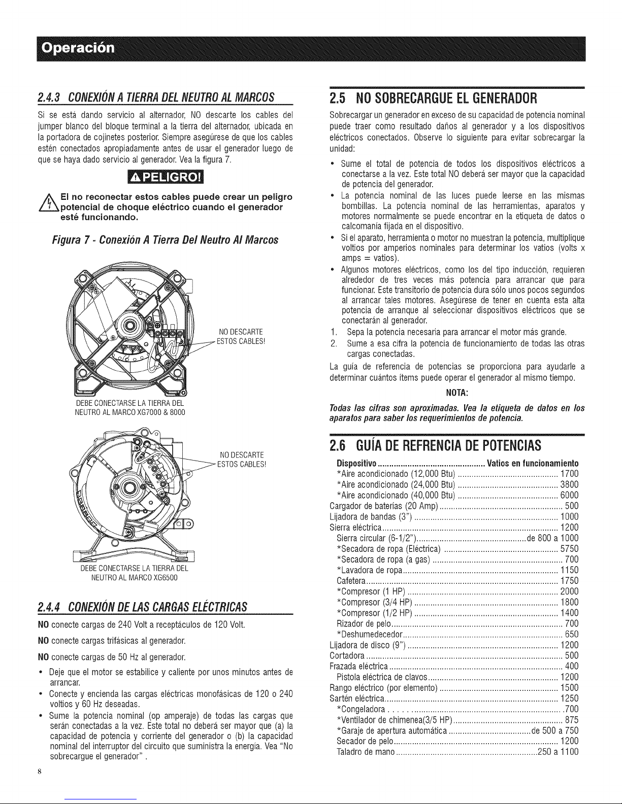
2.4.3 CONEX/ONA T/ERRADELNEUTROAL MARCOS
Si se esta dando servicio al alternador, NO descarte los cables del
jumper blanco del bloqueterminal a la tierra del alternador,ubicada en
la portadoradecojinetesposterior.Siempreaseguresedequelos cables
esten conectados apropiadamenteantes de usar el generadorluego de
quese hayadado servicioalgenerador.Veala figura 7.
El no reconectar estos cables puede crear un peligro
potential de choque el6ctrico cuando el generador
est6 funcionando.
Figura 7 - Conexibn A Tierra De/Neutro A/Marcos
NODESCARTE
DEBECONECTARSELA TIERRADEL
NEUTROALMARCOXGT000& 8000
2.5 NO SOBRECARGUEELGENERADOR
Sobrecargarungeneradorenexcesodesu capacidaddepotencianominal
puede traer como resultado dahos al generador y a los dispositivos
electricos conectados. Observe Io siguiente para evitar sobrecargar la
unidad:
Sume el total de potencia de todos los dispositivos electricos a
conectarsea lavez.Estetotal NOdebera,ser mayor que la capacidad
de potenciadel generador.
• La potencia nominal de las luces puede leerse en las mismas
bombillas. La potencia nominal de las herramientas, aparatos y
motores normalmentese puede encontrar en la etiquetade datos o
calcomaniafijada eneldispositivo.
• Si el aparato,herramientao motor nomuestranla potencia,multiplique
voltios pot amperios nominales paradeterminar los vatios (volts x
amps = vatios).
• Algunos motores electricos, como los del tipo induccion, requieren
alrededor de tres veces mas potencia para arrancar que para
funcionar.Estetransitorio depotenciadurasolo unos pocossegundos
al arrancar tales motores. Asegurese de tener en cuenta esta alta
potencia de arranque al seleccionar dispositivos electricos que se
conectaranal generador.
1. Sepala potencia necesariaparaarrancarel motor ma.sgrande.
2. Sume a esa cifra la potenciade funcionamiento de todas las otras
cargas conectadas.
La guia de referencia de potencias se proporciona para ayudarle a
determinarcua.ntositemspuedeoperar el generadoral mismotiempo.
NOTA:
Todas /as cifras son apreximadas. Veala etiqueta de datos en los
aparatos para saber los requerimientos de poteneia.
_ NODESCARTE
DEBECONECTARSELATIERRADEL
NEUTROALMARCOXG6500
2.4.4 CONEXlONBELASCARGASEL CTRICAS
NOconecte cargasde 240 Volta receptaculosde 120Volt.
NOconecte cargastrifasicas al generador.
NOconecte cargasde 50 Hzal generador.
• Deje que el motor se estabilice y calientepor unos minutos antes de
arrancar.
• Conectey enciendalas cargas electricasmonofa.sicasde 120 o 240
voltios y 60 Hzdeseadas.
• Sume la potencia nominal (op amperaje) de todas las cargas que
seran conectadasa la vez. Estetotal no deberaser mayor que (a) la
capacidadde potencia y corriente del generadoro (b) la capacidad
nominal delinterruptordel circuitoque suministrala energia.Vea "No
sobrecargueel generador".
2.6 GUiADEREFRENOIADEPOTENCIAS
Dispositivo ............................................... Vatiosen funcionamiento
*Aire acondicionado(12,000 Btu)............................................ 1700
*Aire acondicionado(24,000 Btu)............................................ 3800
*Aire acondicionado(40,000 Btu)............................................ 6000
Cargadorde baterias(20Amp)...................................................... 500
Lijadorade bandas(3") ............................................................... 1000
Sierraelectrica............................................................................. 1200
Sierracircular (6-1/2") ................................................de 800 a 1000
*Secadorade ropa (Electrica) .................................................. 5750
*Secadorade ropa (a gas) ......................................................... 700
*Lavadora deropa.................................................................... 1150
Cafetera.................................................................................... 1750
*Oompresor (1 HP).................................................................. 2000
*Oompresor (3/4 HP)............................................................... 1800
*Oompresor (1/2 HP)............................................................... 1400
Rizadordepelo........................................................................... 700
*Deshumedecedor...................................................................... 650
Lijadorade disco (9") .................................................................. 1200
Oortadora...................................................................................... 500
Frazadaelectrica............................................................................ 400
Pistola electricade clavos......................................................... 1200
Rangoelectrico (pot elemento).................................................... 1500
Sartenelectrica............................................................................ 1250
*Congeladora....................................................................... 700
*Ventilador de chimenea(3/5HP)................................................ 875
*Garaje de aperturaautomatica....................................de 500a 750
Secadorde pelo........................................................................ 1200
Taladrode mano..............................................................250 a 1100
Page 33
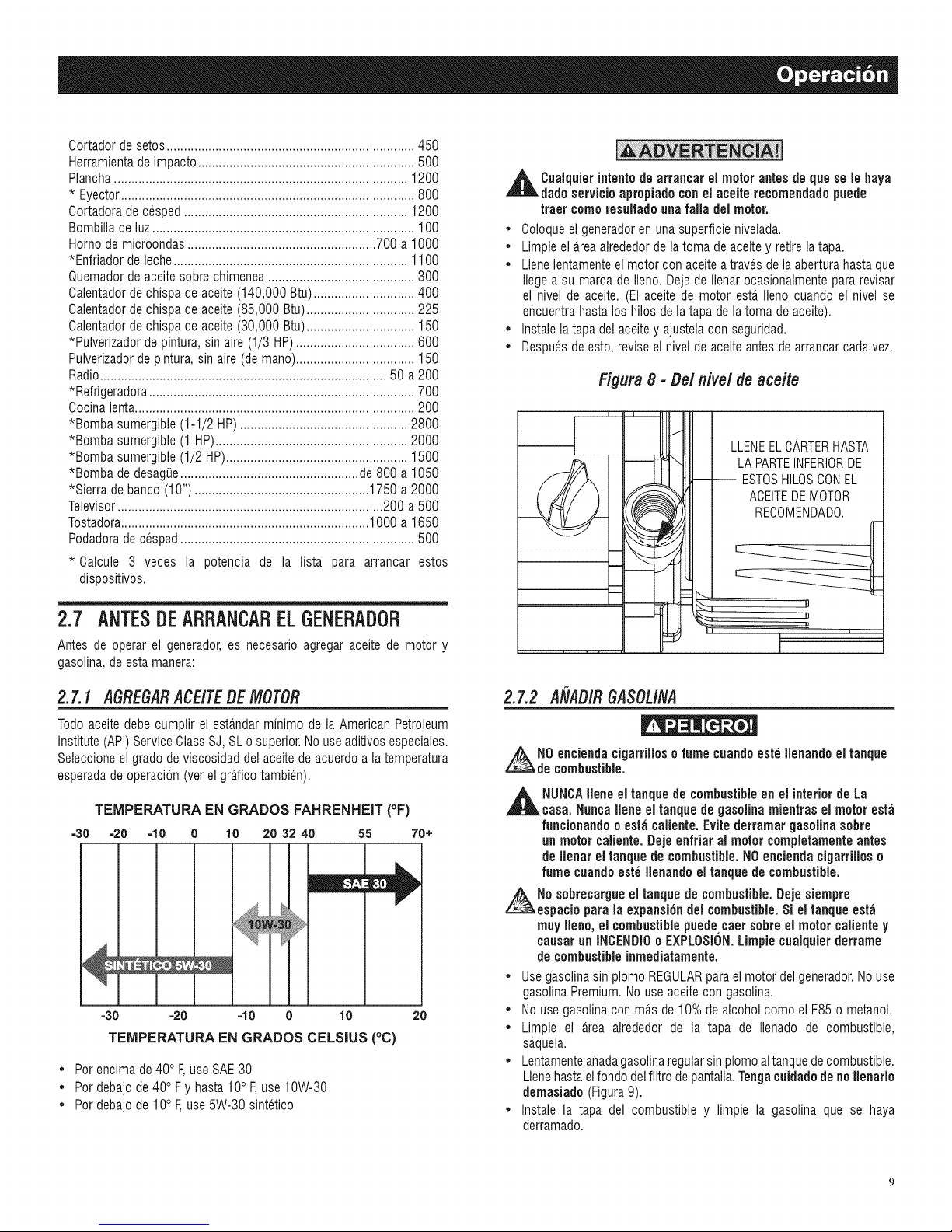
Cortadordesetos.......................................................................450
Herramientadeimpacto..............................................................500
Plancha....................................................................................1200
*Eyector....................................................................................800
Cortadoradecesped................................................................1200
Bombilladeluz...........................................................................100
Homodemicroondas......................................................700a1000
*Enfriadordeleche...................................................................1100
Quemadordeaceitesobrechimenea..........................................300
Calentadordechispadeaceite(140,000Btu).............................400
Calentadordechispadeaceite(85,000Btu)...............................225
Calentadordechispadeaceite(30,000Btu)...............................150
*Pulverizadordepintura,sinaire(1/3HP)..................................600
Pulverizadordepintura,sinaire(demano)..................................150
Radio..................................................................................50a200
*Refrigeradora............................................................................700
Cocinalenta................................................................................200
*Bombasumergible(1-1/2HP)................................................2800
*Bombasumergible(1HP).......................................................2000
*Bombasumergible(1/2HP)....................................................1500
*BombadedesagiJe...................................................de800a1050
*Sierradebanco(10")..................................................1750a2000
Televisor............................................................................200a500
Tostadora.......................................................................1000a1650
Podadoradecesped...................................................................500
* Calcule 3 veces la potencia de la lista para arrancar estos
dispositivos.
,_ Cuaiquierintent{)de el motor antes de le
dado servicio apropiado conel aceite recomendado puede
truer comeresultadounafalla del motor.
• Coloqueelgeneradoren una superficie nivelada.
• Limpie el a_reaalrededorde latoma deaceitey retirelatapa.
• Llenelentamenteel motor con aceitea travesde laaberturahastaque
liegea su marcade lien& Deje de Ilenarocasionalmentepara revisar
el nivel de aceite. (El aceite de motor esta_Ileno cuando el nivel se
encuentrahasta los hilos de la tapade latoma deaceite).
• Instale latapa del aceite y ajustelacon seguridad.
• Despuesde esto, revise el nivelde aceiteantes de arrancar cadavez.
Figura 8 -Oel nivel de aceite
arrancar
m
LA PARTEINFERIORDE
-- ESTOSHILOSCONEL
ACEITEDEMOTOR
!_ LLENEELCARTERHASTA
que
8e
baya
2.7 ANTESDEARRANCARELGENERADOR
Antes de operar el generador,es necesario agregar aceite de motor y
gasolina,de estamanera:
2.7.1 ASRESARACEITEDEMOTOR
Todo aceitedebecumplir el estandarminimo de la American Petroleum
Institute(API)ServiceClassSJ, SLo superior.Nouse aditivosespeciales.
Seleccioneel gradodeviscosidad del aceite deacuerdo a latemperatura
esperadade operacion (verel gra.ficotambien).
TEMPERATURA EN GRADOS FAHRENHEIT (OF)
=30 =20 =10 0 10 20 32 40 55 70+
=30" =20 ' =10 0 10 20
TEMPERATURA EN GRADOS CELSIUS (°C)
• Por encimade 40°F,useSAE30
• Por debajode 40° Fy hasta 10° F,use 10W-30
• Por debajode 10° F,use5W-30 sintetico
i
2.7.2 A[IAOIR8ASOLINA
z_N0 encienda cigarrilloso fume cuandoeste Ilenando el tanque
de combustible.
,_ NUNCAIlene eltanque de combustibleen el interior de La
casa. Nunca Ilene eltanque de gasolina mientras el motoresta
funcionando o esta caliente.Evite derramar gasolina sobre
un motor caliente.Dejeenfriar al motorcompletamenteantes
de Ilenar el tanque de combustible.NOencienda cigarrilloso
fume cuandoeste Ilenandoel tanque de combustible.
No sobrecargue el tanque de combustible.Dejesiempre
espacio para la expansi6n del combustible.Si el tanque esta
muy Ileno,el combustiblepuede caer sobre el motorcalientey
causarun INOENDI0o EXPLOSION.Limpiecualquierderrame
de combustibleinmediatamente.
• Usegasolinasinplomo REGULARparael motor delgenerador.Nouse
gasolinaPremium.No use aceitecon gasolina.
• No use gasolina con mas de 10%de alcohol como el E85o metanol.
• Limpie el area alrededor de la tapa de Ilenado de combustible,
sa_quela.
• Lentamenteafiadagasolinaregularsin plomo altanquedecombustible.
Llenehastaelfondo delfiltrodepantalla.Tengacuidadode noIlenarlo
demasiado (Figura9).
• Instale la tapa del combustible y limpie la gasolina que se haya
derramado.
Page 34
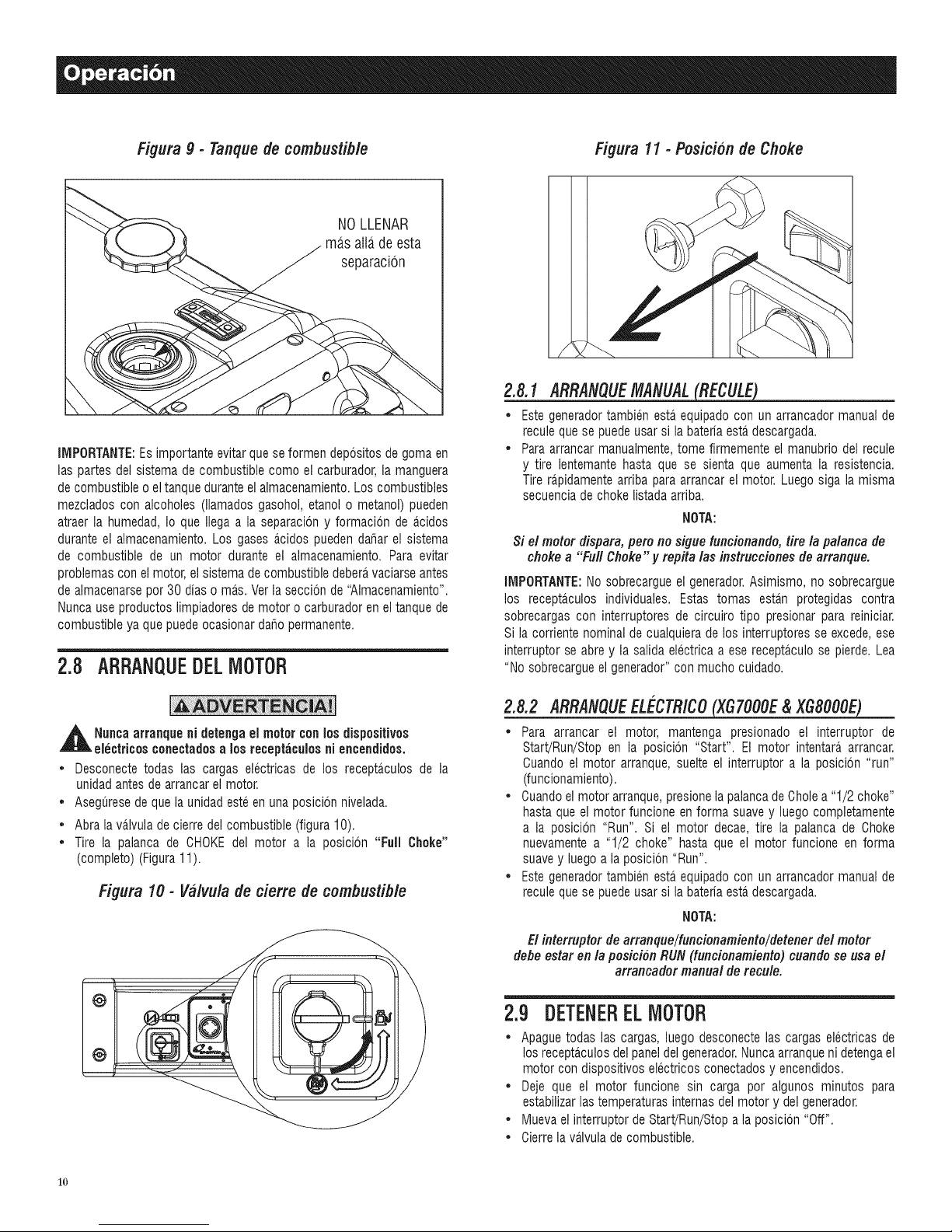
Figura9 - Tanquedecombustible
NOLLENAR
ma,s atlade esta
separacion
IMPORTANTE:Esimportanteevitarque se formen depositosde goma en
las partesdel sistema de combustible como el carburador,la manguera
de combustibleo eltanque duranteel almacenamiento.Loscombustibles
mezclados con alcoholes (llamados gasohol, etanol o metanol) pueden
atraer la humedad,Io que Ilega a la separaciony formacion de a_cidos
durante el almacenamiento.Los gases acidos puedendaharel sistema
de combustible de un motor durante el almacenamiento. Para evitar
problemascon elmotor,el sistema decombustible debera,vaciarseantes
de almacenarsepor 30 diaso mas. Ver la seccion de "AImacenamiento".
Nuncause productos limpiadoresde motor o carburadoren el tanque de
combustibleya que puedeocasionardaho permanente.
2.B ARRANQUEDELMOTOR
2.8.1 ARRANQUEMANUAL
* Este generadortambienestaequipado con un arrancador manual de
reculeque se puede usarsi la bateriaestadescargada.
* Paraarrancarmanualmente,tome firmemente el manubrio del recule
y tire lentemantehasta que se sienta que aumenta la resistencia.
Tire rapidamentearriba para arrancarel motor. Luegosiga la misma
secuenciade choke listadaarriba.
NOTA:
Si el motordispara, pero no sigue funcionando, tire la palanca de
choke a "Full Choke" y repRa las instruccionesde arranque.
IMPORTANTE:No sobrecargue el generador.Asimismo, no sobrecargue
los recepta_culosindividuales. Estas tomas esta,n protegidas contra
sobrecargas con interruptores de circuiro tipo presionar para reiniciar.
Si la corriente nominalde cualquierade los interruptoresse excede,ese
interruptor seabre y la salida electricaa ese recepta,culo se pierde.Lea
"No sobrecargueel generador"con mucho cuidado.
_ll uncaarranque ni detenga el motor con los dispositivos
electricosconectadusa losreceptaculosni encendidos.
* Desconecte todas las cargas electricas de los recepta,culos de la
unidadantesde arrancarel motor.
* Aseguresede que launidad esteen una posicion nivelada.
* Abrala valvula de cierre delcombustible (figura 10).
* Tire la palanca de CHOKEdel motor a la posicion "Full Choke"
(completo) (Figura11).
Figura 10- Va/vuladederre de combustible
/
2.8.2 ARRANQUEEL_'CTRICO___
* Para arrancar el motor, mantenga presionado el interruptor de
Start!Run/Stop en la posicion "Start". El motor intentara arrancar.
Cuando el motor arranque,suelte el interruptor a la posicion "run"
(funcionamiento).
* Cuandoel motor arranque,presionelapalancadeCholea "1/2 choke"
hastaque el motor funcione enforma suave y luegocompletamente
a la posicion "Run". Si el motor decae, tire la palanca de Choke
nuevamentea "1/2 choke" hasta que el motor funcione en forma
suavey luegoa la posicion "Run".
* Este generadortambienestaequipado con un arrancador manual de
reculeque se puede usarsi la bateriaesta.descargada.
NOTA:
El interruptor dearranque/funcionamiento/detener del motor
defle estar en la posicion RUN (funcionamiento) cuando seusa el
arrancador manual de recule.
2.9 DETENERELMOTOR
* Apaguetodas las cargas, luego desconecte las cargas electricas de
los recepta_culosdel paneldelgenerador.Nuncaarranqueni detengael
motor con dispositivoselectricosconectadosy encendidos.
* Deje que el motor funcione sin carga por algunos minutos para
estabilizarlas temperaturasinternasdelmotor y del generador.
* Muevaelinterruptor de Start/Run/Stopa la posicion "Off".
* Cierrela va.lvuladecombustible.
1o
Page 35

2.10SISTEMADEAPAGADOP0RBAJAPRESION
DEACEITE
El motor estaequipado con un sensor de presionque apagael motor en
forma automaticacuandola presion deaceitebaja a menosde 5psi. Si el
motorse apagay eltanque decombustible tienesuficiente gaolina,revise
el niveldeaceitedemotor. Unretardoincorporado al sistemadeapagado
por baja presion de aceite permite que la presion de aceite se acumule
duranteelarranque.Elretardo permitequeel motor funcione alrededorde
10 segundosantesde sensarlapresionde aceite.
Si el sistemadetecta una baja presion de aceitedurantela operacion, el
motor seapaga.
2.10.1 REIN/C/AR
Siesta tratandode reiniciar el motor dentrode los 10 segundosdespues
de quese apago,elmotor puedeque noarranque.El sistema necesitade
5 a 10 segundospara poderreiniciarse.
Si el motor se reinicia luego de apagarsey no se ha corregido la baja
presbn de aceite,el motor funcionara,alrededorde10 segundoscomo se
describearribay sedetendra..
2.11CARGADELABATEBIA
,_Las baterias almacenadassueltanunexplosivo gas de
hidr6genoal recargarse.Una mezcla explosiva permanecer;i
alrededor de la bateria pot largo tiempo luego de que se haya
cargado.La re;is ligerachispapuedeencender el hidr6geno
y causaruna expiosi6n. Unaexplosion asi puededestruirla
bateria ycausar cegueray otrosda_osserios.
No permitaque lumen,haganfuegoabierto, chispaso cualquier
otrafuentede calor alrededor de la bated& Use guantes
protectores,galas y delantalde goma cuandotrabaje alrededor
de la bated& El fluidoelectrolitico de la bateria es una solucion
de acido sulfuricoextremadamente corrosivaque puedecausar
severasquemaduras. Si ocurreunderramelave el ;irea con
agua limpia inmediatamente.
Useel conectordel cargadordebateriaparamantenerla bateriacargaday
lista para usarse.La cargade labateriadebera,hacerseenuna ubicacion
seca.
1. Oonecteel cargador en el conector de "Entrada de cargador de
bateria", ubicado en el panel de control. Oonecte el extremo del
recepta.culode pared delcargador de la bateria enuna toma de 120
VOA.
2. Desconecteel cargador de bateria de la toma de la pared y del
conectordel paneldecontrol cuando el generadorvayaa usarse.
NOTA:
No useel cargador dem bateriasper mas de 48 horas en una carga.
3.1 CBONOGBAIV]ADEMANTENIMIENTO
Siga los intervalos del calendario.Se requiereun servicio mas frecuente
cuando se operaen condiciones adversascomo lasquese indica abajo.
Revise el nivel de aceite en cada uso
Oambio de aceite y filtro$ *Cada temporada o cada 100 horas
Limpiar pantalla del sup de chispas Cada cambio de estacion
Revise la claridad de la valvula ***Cada temporada o cada 100 horas
Servicio al limpiador de aire **Oada temporada o cada 200 horas
Reemplazo de bujias Cada cambio de estacion
:i: Cambieel aceite luegode lasprimeras30 horasde operaci0ny luegoencada
cambio de estaci0n.
* Cambie el aceite y el filtro de aceite cada mes si opera bajo condiciones
pesadas decarga oaltas temperaturas.
** Limpie con mas frecuencia bajo condiciones de operacion que involucren
polvo y suciedad. Reemplacelas piezas del limpiador de aire si estan muy
sucias.
*** Revise la claridad de la valvula y ajustela si es necesario luego de las
primeras 50 horas deoperacion y cada 100 horas luego de ello.
3.2 ESPECIFICACIONESDELPBODUCTO
3.2.1 ESPECiFICACiONESDELGENERADOR
Modelo # ............................................................. 005800-0, 005747-0
Potenciam_ nominal............................................................. 8.0 kW**
Potenciadetransitorio.................................................................. 10 kW
VoltajeAC nominal.................................................................... 120/240
CargamaximaACnominal
Corriente@ 240V.......................................................... 33.3 Amps**
Oorriente@ 120V.......................................................... 66.7 Amps**
Frecuencianominal................................................ 60 Hz@ 3600 RPM
Fase..................................................................................... Monofa_sico
VoltajeDOnominal.................................................................... 12 Volts
Tipo de Bateria............................................................... 10 AH, 12 VDC
Modelo # ............................................................. 005797-0, 005798-0
Potenciam_ nominal............................................................. 7.0 kW**
Potenciadetransitorio............................................................... 8.75 kW
VoltajeAC nominal.................................................................... 120/240
CargamaximaACnominal
Corriente@ 240V.......................................................... 29.2 Amps**
Oorriente@ 120V.......................................................... 58.3 Amps**
Frecuencianominal................................................ 60 Hz@ 3600 RPM
Fase..................................................................................... Monofa_sico
VoltajeDOnominal.................................................................... 12 Volts
Tipo de Bateria............................................................... 10 AH, 12 VDC
Modelo# .............................................................................. 005796-0
Potenciam_ nominal............................................................. 6.5 kW**
Potenciadetransitorio............................................................... 8.13 kW
VoltajeAC nominal.................................................................... 120/240
CargamaximaACnominal
Oorriente@ 240V .......................................................... 27.1 Amps**
Oorriente@ 120V.......................................................... 54.2 Amps**
Frecuencianominal................................................ 60 Hz@ 3600 RPM
Fase..................................................................................... Monofa.sico
** Las potenciasy corrientes maximas estansujetas a, y limitadas por,factores
tales como contenido en BTUsdel combustible, altitud, condiciones delmotor,
etc. Lapotencia maxima disminuyealrededordel 3.5%por cada 1000 pies
sobre elnivel del mar,y tambiendisminuira alrededordel 1% por cada6°0
(10°F)por encimade los 16°C(60°F) detemperaturaambiente.
11
Page 36
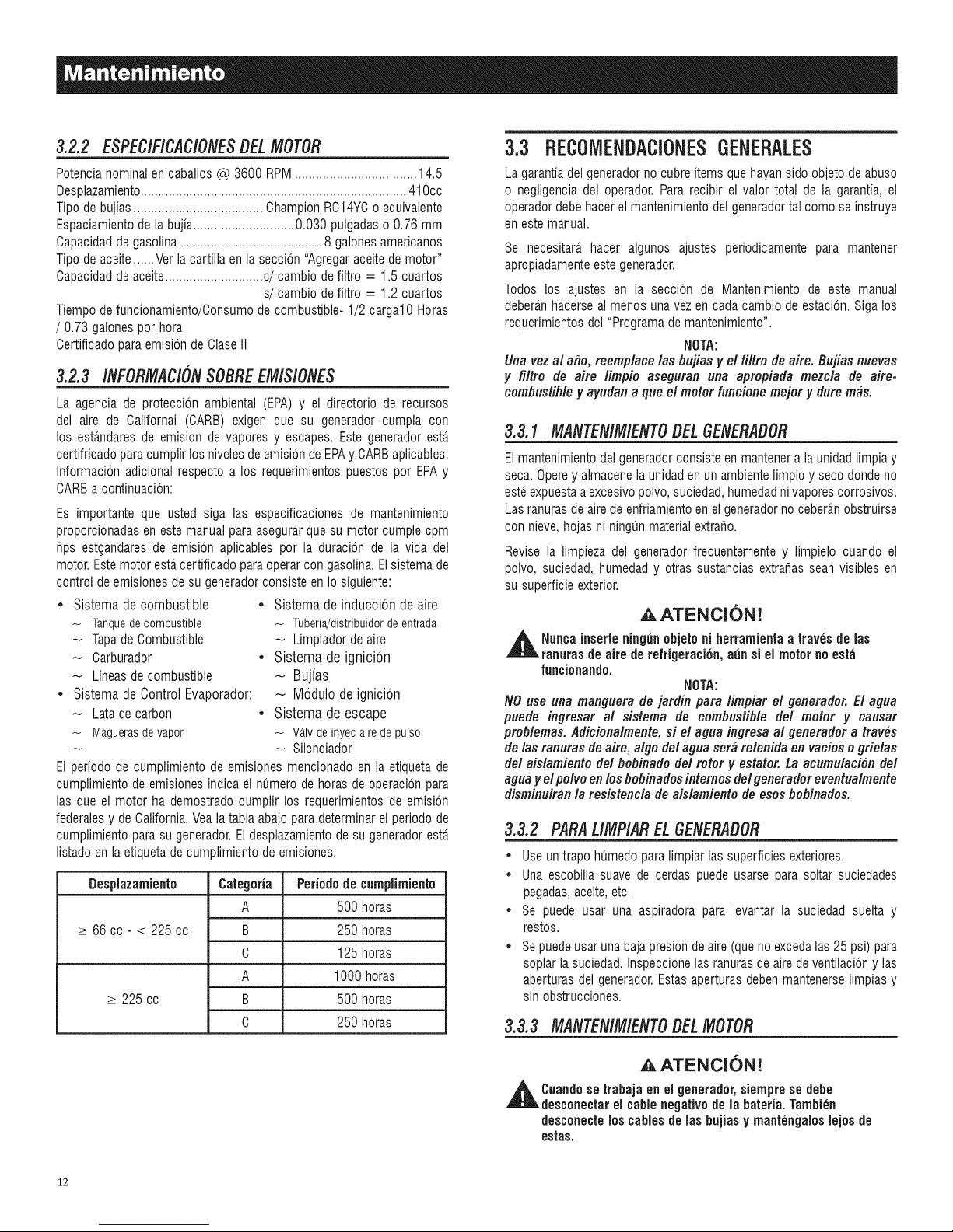
3.2.2 ESPEC/F/CAC/ONESBELMOTOR
Potencianominalen caballos @ 3600 RPM................................... 14.5
Desplazamiento............................................................................ 410cc
Tipode bujias..................................... ChampionRC14YCo equivalente
Espaciamientodelabujia.............................0.030 pulgadaso 0.76 mm
Capacidadde gasolina......................................... 8 galonesamericanos
Tipode aceite......Ver la cartilla en la seccion "Agregaraceitede motor"
Capacidadde aceite............................c/cambio defiltro = 1.5 cuartos
s/cambio defiltro = 1.2 cuartos
Tiempodefuncionamiento/Consumode combustible- 1/2 cargal0 Horas
/ 0.73 galonespor hora
Certificado paraemisionde ClaseII
3.2.3 /NFORMAC/ONSOBREEM/SlONES
La agencia de proteccion ambiental (EPA) y el directorio de recursos
del aire de Californai (CARB) exigen que su generador cumpla con
los estandaresde emision de vaporesy escapes. Este generadoresta
certifricado paracumplirlosnivelesdeemision deEPAy CARBaplicables.
Informacion adicional respecto a los requerimientospuestos por EPAy
CARBacontinuacion:
Es importante que usted siga las especificaciones de mantenimiento
proporcionadasen estemanual paraasegurarque sumotor cumple cpm
tips estgandaresde emision aplicables por la duracion de la vida del
motor.Estemotorestacertificado paraoperarcon gasolina.Elsistemade
control de emisionesde su generadorconsiste en Io siguiente:
* Sistema de combustible * Sistema de induccion de aire
- Tanquedecombustible - Tuberia/distribuidordeentrada
Tapade Combustible - Limpiador deaire
Carburador • Sistema de ignicion
Lineasde combustible _ Bujias
, Sistema de Control Evaporador: - Modulo de ignicion
Latade carbon • Sistema de escape
- Maguerasdevapor - VANdeinyecairedepulso
-- Silenciador
El periodo de cumplimiento de emisiones mencionado en la etiqueta de
cumplimiento de emisionesindica elnumerode horas de operacionpara
las que el motor ha demostrado cumplir los requerimientosde emision
federalesy de California.Veala tabla abajoparadeterminarel periodode
cumplimiento parasu generador.El desplazamientodesu generadoresta,
listado en la etiquetade cumplimientode emisiones.
Desplazamiento Categoria Periodo de cumplimiento
A 500 horas
_>66 cc- < 225 cc B 250 horas
C 125 horas
A 1000 horas
_>225 cc B 500 horas
C 250 horas
3.3 REC01VlENDACiONESGENERALES
La garantiadel generadornocubreitems quehayan sido objeto deabuso
o negligenciadel operador. Para recibir el valor total de la garantia, el
operadordebehacerelmantenimientodel generadortal como se instruye
en estemanual.
Se necesitara_hacer algunos ajustes periodicamente para mantener
apropiadamenteeste generador.
Todos los ajustes en la seccion de IVlantenimientode este manual
deberanhacerse al menos unavez en cada cambio de estacion.Siga los
requerimientosdel "Programademantenimiento".
NOTA:
Una vezal afio, reemplace los flujias y el filtro de aire. Bujias nuevas
y filtro de aire limpio aseguran una apropiada mezcla de aire-
combustib/e y ayudan a que el motor funcione mejor y dure mas.
3.3.1 MANTEN/M/ENTODEL6ENERADOR
Elmantenimientodel generadorconsisteen mantenera la unidadlimpia y
seca. Operey almacenela unidaden un ambientelimpio y seco dondeno
esteexpuestaaexcesivopolvo,suciedad,humedadnivapores corrosivos.
Lasranurasde airede enfriamientoen elgeneradornocebera.nobstruirse
con nieve, hojas ni ningun materialextrafio.
Revise la limpieza del generadorfrecuentementey limpielo cuando el
polvo, suciedad,humedady otras sustancias extrafias sean visibles en
su superficieexterior.
AATENCION!
,_ Nuncainserte ning0n objetoni herramientaa troves de los
ranurasde aire de refrigeration, aunsi el motor no esta
funcionando.
NOTA:
NO use una manguera de jardiu tiara limfliar el generador. El agua
puede ingresar al sistema de combustible del motor y causar
problemas. Adicionalmente, si el agua ingresaal generador a troves
delos ranuras de aire, algo del agua seraretenida en vacios ogrietas
del aislamiento del bobinado del rotor y estator. La acumulaci#u del
aguayelpolvo en los bobinadosintemosdelgenerador eventualmente
disminuiran la resistencia de aislamiento de esos bobinados.
3.3.2 PARAL/MP/ARELGENERADOR
• Use untrapo humedo paralimpiar lassuperficies exteriores.
• Una escobillasuave de cerdas puede usarse para soltar suciedades
pegadas,aceite,etc.
• Se puede usar una aspiradora para levantar la suciedad suelta y
restos.
• Sepuedeusar unabaja prestondeaire(queno excedalas 25 psi) para
soplarla suciedad. Inspeccionelas ranurasdeairedeventilaciony las
aberturasdel generador.Estasaperturasdebenmantenerselimpias y
sin obstrucciones.
3.3.3 MANTEN/MIENTODELMOTOR
12
,& ATENCION!
,_l Cuandose trabaja en el generador, siempre se debe
desconectar el cable negativode la bateria. Tambien
desconectelos cablesde las bujias y mantengalos lejos de
estas.
Page 37
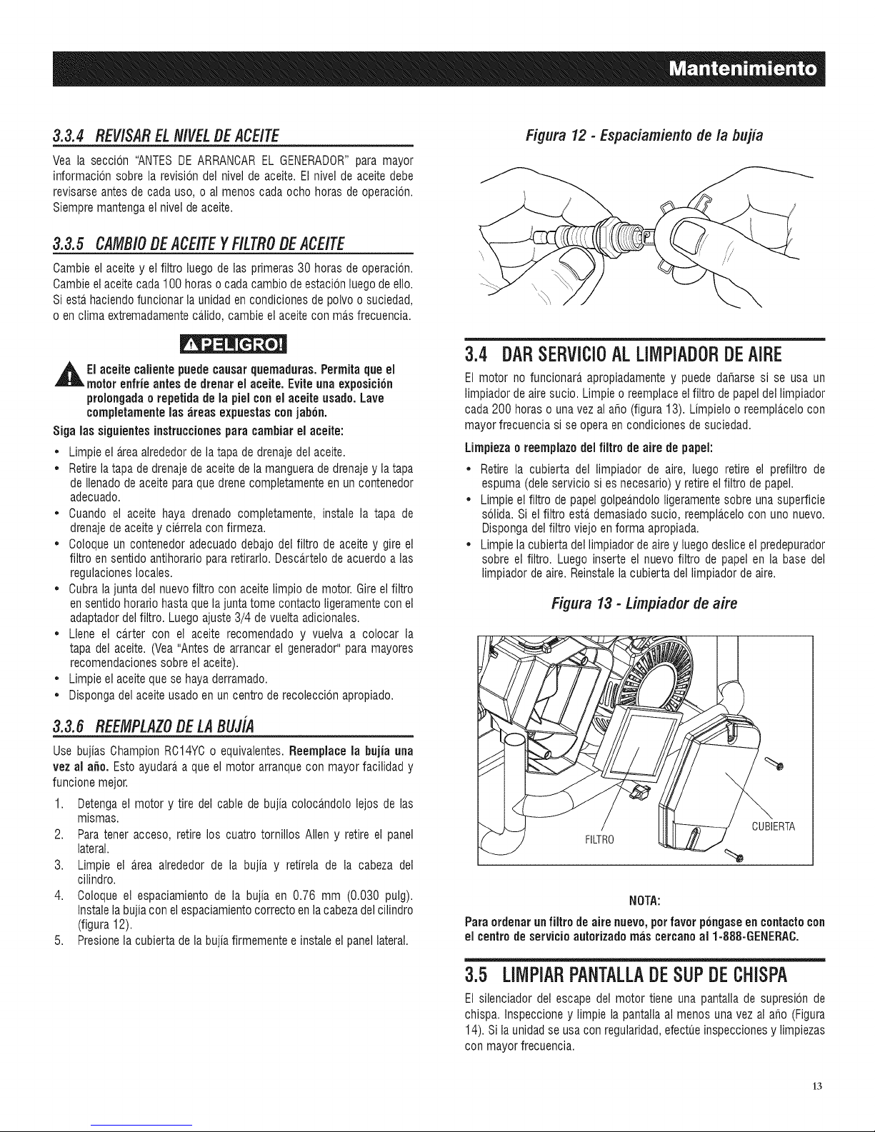
3.3.4 REV/SARELN/VELDEACE/TE
Yea la seccion "ANTESDEARRANCAREL GENERADOR"para mayor
informacbn sobrela revision del nivelde aceite.El nivel de aceitedebe
revisarseantesde cadauso, o al menos cada ocho horas de operacion.
Siempremantengael nivelde aceite.
3.3.5 CAMBiODEACEITEYF/LTRODEACEITE
Cambieelaceite y el filtro luego de las primeras 30 horas de operacion.
Cambieel aceitecada 100 horaso cadacambio deestacionluegode ello.
Siesta haciendofuncionarlaunidad encondiciones depolvo o suciedad,
oen clima extremadamenteca,lido,cambie el aceitecon ma,s frecuencia.
,_EI aceite calientepuedecausarquemaduras. Permita que el
motor enfrie antes de drenar el aceite. Evite unaexposicion
prolongadaorepetidade la pielcon el aceite usado.Lave
completamenteinsareas expuestas conjabon.
Sign ins siguientes instruccionespara cambiar el aceite:
• Limpie el areaalrededorde latapa de drenajedelaceite.
• Retirela tapade drenajede aceitedelamanguerade drenajey latapa
de Ilenadodeaceite paraquedrene completamenteen un contenedor
adecuado.
• Cuando el aceite haya drenado completamente, instale la tapa de
drenajede aceitey cierrela confirmeza.
• Coloqueun contenedoradecuadodebajo del filtro de aceite y gire el
filtro en sentido antihorariopararetirarlo. Desca,rtelo deacuerdo alas
regulacioneslocales.
• Cubralajunta del nuevofiltro con aceitelimpio de motor.Gireelfiltro
ensentidohorario hastaque la juntatome contacto ligeramentecon el
adaptadordelfiltro. Luegoajuste 3/4 devuelta adicionales.
• Llene el carter con el aceite recomendado y vuelva a colocar la
tapa del aceite. (Vea "Antesde arrancarel generador"para mayores
recomendacionessobre el aceite).
• Limpie el aceitequese haya derramado.
• Dispongadelaceite usadoen uncentro de recoleccbn apropiado.
Figura 12 - Espaciamiento de la bujia
3.4 DARSERVICIOALLIMPiADORDEAIRE
El motor no funcionara apropiadamentey puede daharse si se usa un
limpiadordeaire sucio. Limpieo reemplaceelfiltro depapeldel limpiador
cada200 hornso unavez al aho (figura 13). Limpieloo reempla,celocon
mayor frecuenciasi se operaen condiciones desuciedad.
Limpiezaoreemplazo delfiltro de aire de papel:
• Retire la cubierta del limpiador de aire, luego retire el prefiltro de
espuma(deleservicio si es necesario)y retireel filtro de papel.
• Limpie el filtro de papelgolpeandololigeramentesobre una superficie
solida. Si el filtro esta demasiadosucio, reemplacelocon uric nuevo.
Dispongadel filtro viejo enforma apropiada.
• Limpie la cubiertadellimpiador de airey luegodesliceel predepurador
sobre el filtro. Luego inserte el nuevo filtro de papel en la base del
limpiadorde aire.Reinstalela cubierta dellimpiador de aire.
Figura 13 - Limpiador de aire
3.3.6 REEMPLAZODE LABUJiA
Use bujias Champion RC14YCo equivalentes.Reemplaoe la bujia ann
vez al a_o. Esto ayudaraa queel motor arranquecon mayorfacilidad y
funcione mejor.
1. Detengael motor y tire del cable de bujia colocandolo lejos de las
mismas.
2. Paratener acceso, retire los cuatro tornillos Allen y retire el panel
lateral.
3. Limpie el area alrededor de la bujia y retirela de la cabeza del
cilindro.
4. Coloque el espaciamiento de la bujia en 0.76 mm (0.030 pulg).
Instalela bujiacon elespaciamientocorrectoenla cabezadelcilindro
(figura 12).
5. Presionela cubierta dela bujiafirmementee instaleel panel lateral.
FILTRO
CUBIERTA
NOTA:
Paraordenarun filtro de aire nuevo, perfavor p6ngaseen contactocon
el centrode servicio autorizado mas cercanoal 1-888-GENERAC.
3.5 LllVlPiARPANTALLADESUPDECHiSPA
El silenciador del escape del motor tiene una pantallade supresbn de
chispa. Inspeccioney limpie la pantalla al menos una vez al aho (Figura
14). Si la unidadse usa con regularidad,efectueinspeccionesy limpiezas
con mayor frecuencia.
13
Page 38
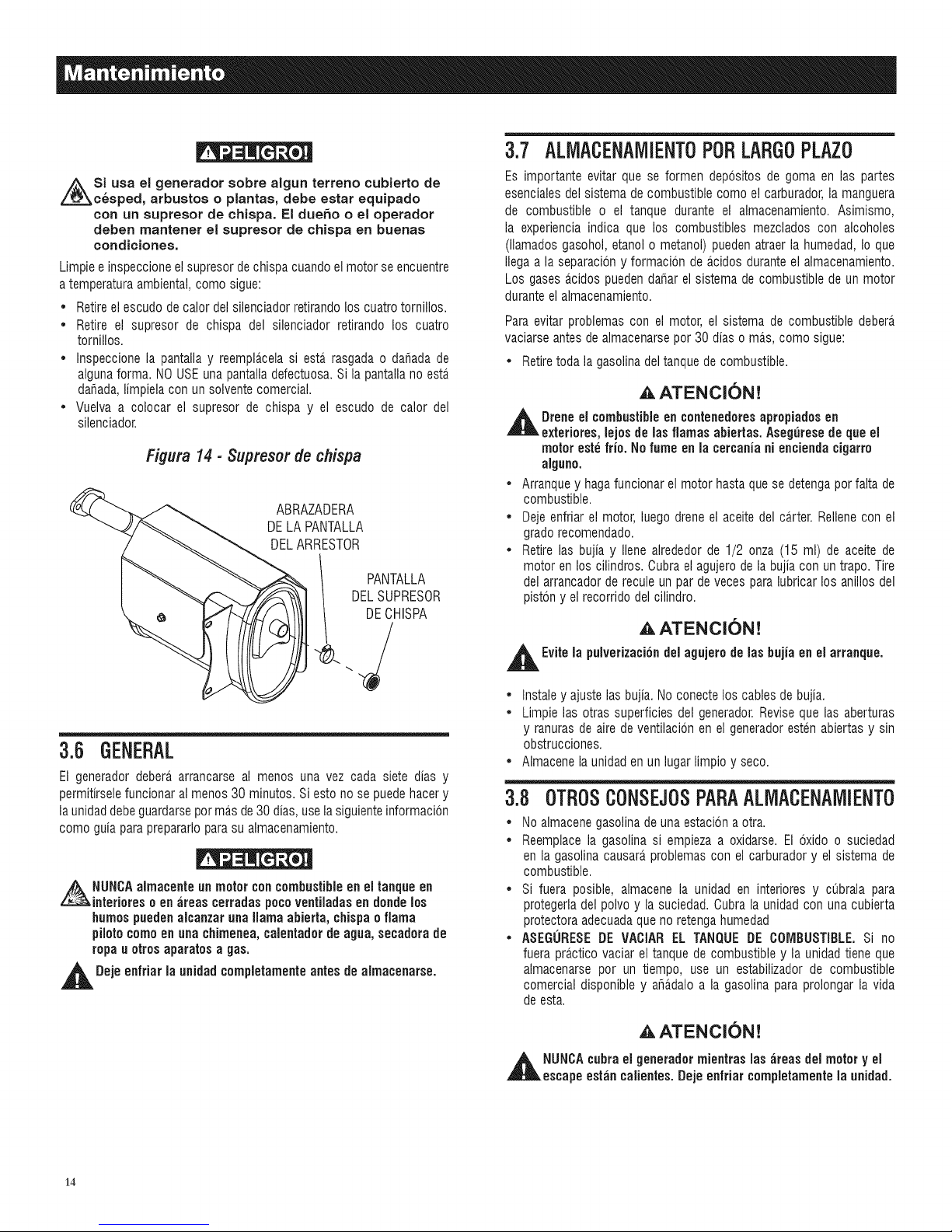
Si usa el generador sobre algun terreno cubierto de
c_sped, arbustos o plantas, debe estar equipado
con un supresor de chispa. El dueho o el operador
deben mantener el supresor de chispa en buenas
condiciones.
Limpieeinspeccioneel supresordechispacuandoelmotor se encuentre
atemperaturaambiental, como sigue:
• Retireel escudo decalor delsilenciador retirandolos cuatrotornillos.
• Retire el supresor de chispa del silenciador retirando los cuatro
tornillos.
• Inspeccione la pantallay reemplacelasiesta_rasgada o dahada de
algunaforma. NOUSEunapantalladefectuosa.Si la pantallano esta.
dahada,limpiela con un solventecomercial.
• Vuelva a colocar el supresor de chispa y el escudo de calor del
silenciador.
Figura14- 3upreser de chispa
ABRAZADERA
DELA PANTALLA
DELARRESTOR
DELSUPRESOR
DECHISPA
II PANTALLA
3.7 ALMACENAMIENT0P0RLARGOPLAZ0
Es importante evitar que se formen depositos de goma en las partes
esencialesdel sistemade combustible como elcarburador,la manguera
de combustible o el tanque durante el almacenamiento. Asimismo,
la experiencia indica que los combustibles mezclados con alcoholes
(llamadosgasohol, etanol o metanol) pueden atraer la humedad, Io que
Ilegaa la separaciony formacion de acidos duranteel almacenamiento.
Los gases acidos puedendahar el sistema de combustiblede un motor
durante el almacenamiento.
Paraevitar problemas con el motor, el sistema de combustible debera.
vaciarseantes de almacenarsepor 30 dias o ma.s,como sigue:
• Retiretoda la gasolinadel tanquede combustible.
AATENCION!
,jl_lL Drene el combustible en contenedores apropiados en
exteriores, lejos de las flamas abiertas. Aseguresede queel
motor este frio. No fume en la cercania ni encienda cigarro
alguno.
• Arranquey hagafuncionar el motorhastaque se detengaporfalta de
combustible.
• Dejeenfriar el motor, luego dreneel aceitedel ca.rter.Rellenecon el
gradorecomendado.
• Retirelas bujia y Ilene alrededorde 1/2 onza (15 ml) de aceite de
motor en los cilindros.Cubra el agujerodela bujia con un trapo. Tire
del arrancador de reculeun par de veces paralubricar los anillos del
piston y el recorrido del cilindro.
,AATENCION!
3.6 GENERAL
El generador debera arrancarse al menos una vez cada siete dias y
permitirselefuncionar almenos 30 minutos. Si esto no se puedehacery
la unidaddebeguardarsepor mas de30dias, usela siguienteinformacion
como guia paraprepararlopara su almacenamiento.
NUNCAalmacente un motor concombustibleenel tanque en
interioreso en ;ireascerradas pocoventiladasen donde los
humospuedenalcanzar unallama abierta, chispa o flama
pilotocomo en una chimenea,calentador de agua, secadora de
ropa uotrosaparatos a gas.
,_1 Deje enfriarla unidad¢ompletamente antes de almacenarse.
,jl_lL Evitela pulverizationdel agujero de las bujia en el arranque.
• Instaley ajuste las bujia. No conectelos cablesde bujia.
• Limpielas otras superficies del generador.Revise quelas aberturas
y ranuras de aire deventilacion en el generadoresten abiertas y sin
obstrucciones.
• Almacene la unidaden un lugarlimpio y seco.
3.B OTROSCONSEJOSPARAALlVlACENAMIENTO
• Noalmacenegasolinadeunaestacion a otra.
• Reemplacela gasolina si empieza a oxidarse. El oxido o suciedad
en la gasolina causara,problemascon el carburadory el sistema de
combustible.
• Si fuera posible, almacene la unidad en interiores y cubrala para
protegerladel polvoy la suciedad.Cubrala unidadcon una cubierta
protectora adecuadaqueno retengahumedad
• ASEGURESEDE VACIAR EL TANQUE DE COMBUSTIBLE.Si no
fuera practico vaciar eltanquede combustibley launidad tiene que
almacenarse por un tiempo, use un estabilizador de combustible
comercial disponible y aha.daloa la gasolina para prolongar la vida
de esta.
AATENCION!
,_h NUNCAcubra el generador mientras las ;ireasdel motor y el
escape eshin ¢alientes. Dejeenfriar ¢ompletamente la unidad.
14
Page 39
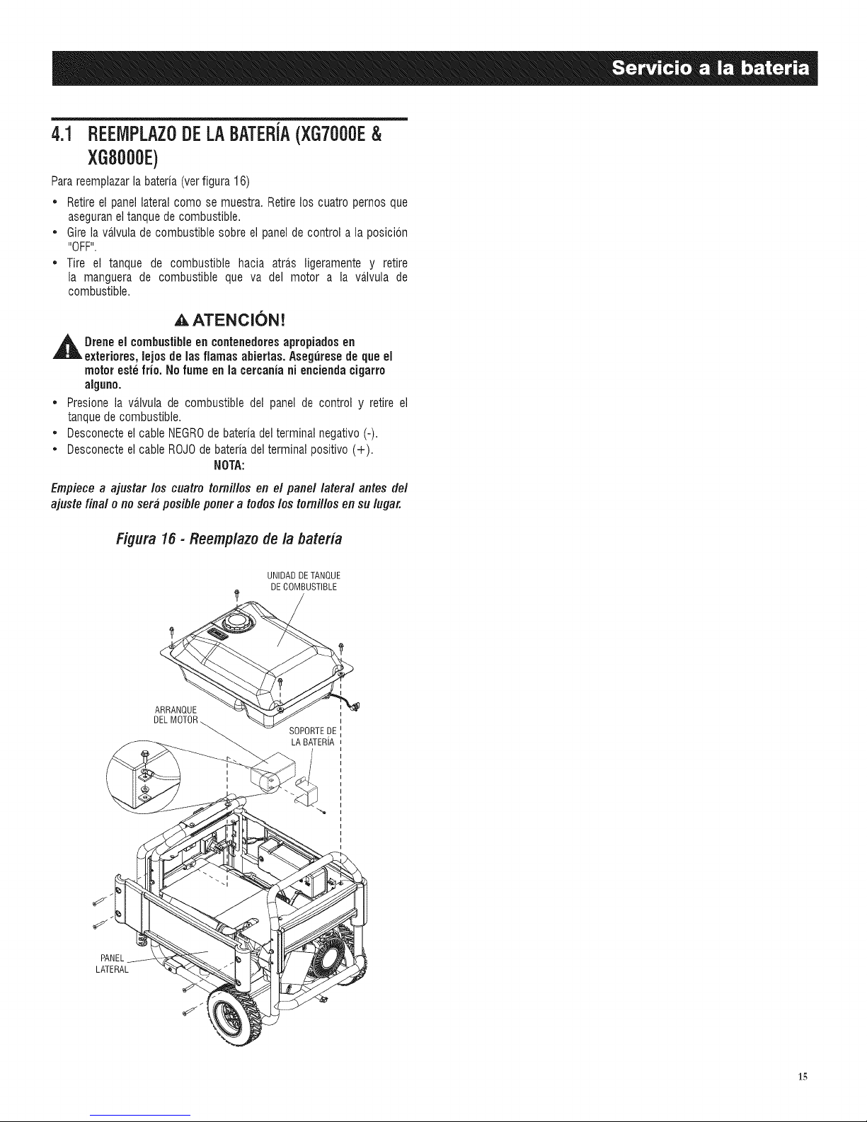
4.1 REEIVIPLAZ0DELABATERJA(XG7000E&
XGB000E)
Parareempiazarla bateria (verfigura 16)
• Retire el panellateral como se muestra. Retirelos cuatro pemos que
aseguraneltanque de combustible.
• Gire la va.lvulade combustible sobre el panelde control a la posicbn
"OFF".
• Tire el tanque de combustible hacia atra.s ligeramente y retire
la manguera de combustible que va del motor a la va.lvulade
combustible.
,A ATENCI(SN!
,_ Dreneel combustibleen contenedoresapropiados en
exteriores, lejosde lasfiamas abiertas. Asegurese de que el
motor estefrio. No fume en lacercania ni enciendacigarro
alguno.
• Presione la valvula de combustible del panel de control y retire el
tanquede combustible.
• Desconecteel cable NEGROde bateria delterminalnegativo (-).
• Desconecteel cable ROJOdebateria delterminalpositivo (+).
NOTA:
Empiece a ajustar los cuatro tomillos en el panel lateral antes del
ajuste final o no sera posible porter a todos los tomillos en su Ingar.
Figura 15 - Reemplazo de la bateria
PANEL
LATERAL
ARRANQUE
DELM(
UNIDADDETANQUE
DECOMBUSTIBLE
SOPORTEDE
LA BATERiA
15
Page 40
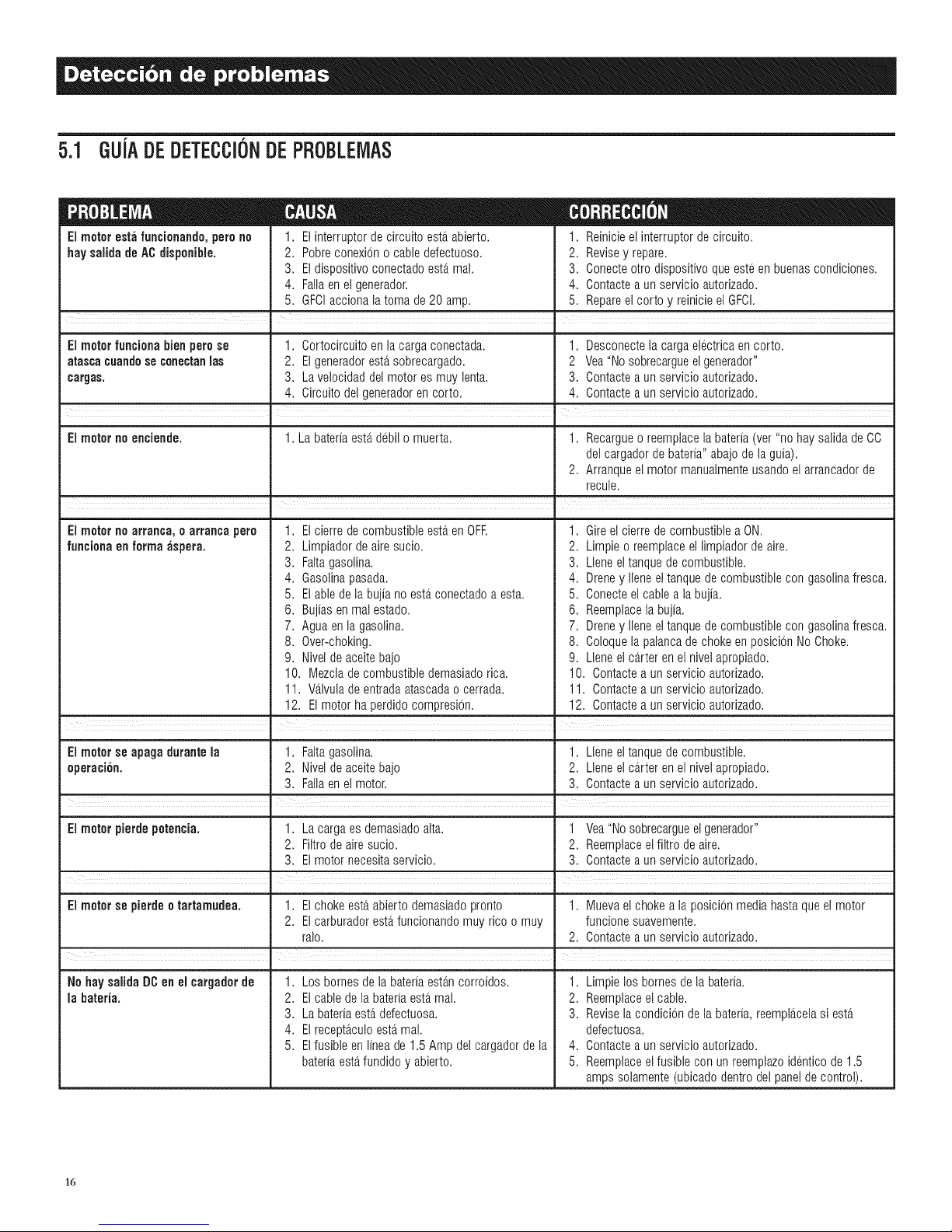
5.1 GUJADEDETECCI6NDEPROBLEMAS
Elmotorestafuncionando,perono
haysaiida deACdisponibie.
1. Elinterrupterdecircuitoesta.abierto.
2. Pobreconexiono cabledefectuoso.
3. Eldispositivoconectadoesta.mai.
4. Fallaenelgenerador.
5. GFCIaccionalatoma de20 amp.
• =
1. Reinicieelinterrupterdecircuito.
2. Revisey repare.
3. Conecteotrodispositivoqueesteenbuenascondiciones.
4. Contacteaunservicioautorizado.
5. Repareelcorto y reinicieel GFCI.
Elmotorfuncienabien perose 1. Cortocircuitoenla cargaconectada. 1. Desconectela cargaelectricaencorto.
atascacuandesecanectanmas 2. Elgeneradoresta.sobrecargado. 2 Vea"Nosobrecargueelgenerador"
cargas. 3. Lavelocidaddel motoresmuylenta. 3. Contacteaunservicioautorizado.
4. Circuitodel generadorencorto. 4. Contactea unservicioautorizado.
Elmeternoenciende. 1. Labateriaesta.debilo muerta. 1. Recargueo reemplacelabateria(ver"no haysaiidadeCO
delcargadordebateria"abajodelaguia).
2. Arranqueelmotor manuaimenteusandoel arrancadorde
recule.
I
EJmotetnoarranca, e arranca pare
funciaflaen farinaaspera.
1. Elcierrede combustibleesteren OFR
2. Limpiadordeairesucio.
3. Faltagasolina.
4. Gasolinapasada.
5. Elabledelabujiano esterconectadoa esta.
6. Bujiasenrealestado.
7. Aguaenla gasolina.
8. Over-choking.
9. Niveldeaceitebajo
10. Mezcladecombustibledemasiadorica.
11. V_tlvulade entradaatascadao cerrada.
12. Elmotor haperdidocompresi6n.
• |
1. Gireel cierredecombustiblea ON.
2. Limpieo reemplaceellimpiadordeaire.
3. Lleneeltanquedecombustible.
4. Dreney Ileneeltanquedecombustiblecongasolinafresca.
5. Conecteel cablea labujia.
6. Reemplacela bujia.
7. Dreney Ileneeltanquedecombustiblecongasolinafresca.
8. Coloquela palancade chokeenposicionNoChoke.
9. Lleneel ca.rteren elnivelapropiado.
10. Contactea unservicioautodzado.
11. Contactea unservicioautodzado.
12. Contactea unservicioautorizado.
!
Elmotorse apagadurantela 1. Faltagasolina. 1. Lleneeltanquedecombustible.
eperaci6n. 2. Niveldeaceitebajo 2. Lleneel ca.rteren elnivelapropiado.
3. Failaenelmotor. 3. Contacteaunservicioautorizado.
I I
Elmeterpierdepetencia. 1. Lacargaesdemasiadoaita. 1 Vea"Nosobrecargueel generador"
2. Filtrodeairesucio. 2. Reemplaceelfiltro deaire.
3. Elmotornecesitaservicio. 3. Contacteaunservicioautorizado.
Elmotorse pierdeetartamudea. 1. Elchokeesterabiertodemasiadopronto 1. Muevaelchokea la posicionmediahastaqueel motor
2. Elcarburadoresterfuncionandomuy ricoo muy funcionesuavemente.
ralo. 2. Contacteaunservicioautorizado.
, .
No haysaiida DCenel cargaderde
la bateria.
1. Losbornesdelabateriaesta.ncorroidos.
2. Elcabledelabateriaesta.mai.
3. Labateriaesta.defectuosa.
4. Elrecepta.culoesta.mai.
5. Elfusibleenlineade1.5 Ampdelcargadordela
bateriaesta.fundidoy abierto.
16
m
1. Limpielosbornesdela bateria.
2. Reemplaceelcable.
3. Reviselacondiciondela bateria,reempla.celasiesta.
defectuosa.
4. Contacteaunservicioautorizado.
5. Reemplaceelfusibleconun reemplazoidenticode1.5
ampssolamente(ubicadodentrodelpaneldecontrol).
Page 41

17
Page 42
DECLARACl6N DE GARANT{A DE CONTROL DE EMISIONES FEDERAL Y DE CALiFORNiA
SUS DERECHOS Y OBMGACIONES DE GARANTiA
El directorio de recursos de aire de California (CARB) y la Agencia de protecci6n ambiental de los Estados Unidos (EPA) junto con
Generac Power Systems, Inc. (Generac) se complacen en expticar la garantia del sistema de control de emisiones para su nuevo
generador det argo 2008 o posterior, equipo nuevo que use motores pequehos de chispa deben estar disehados, construidos
y equipados para cumplir est&ndares anti-smog muy exigentes para et gobierno federal y del Estado de California. Generac
garantizar& los sistemas de emisi6n en su motor por el periodo de tiempo listado abajo siempre que no haya abuso, negligencia,
modificaci6n o mantenimiento inapropiado de su equipo.
Su sistema de control de emisi6n puede inctuir partes como: carburador, sistema de ignici6n, convertidor catalitico, tanque
de combustible, tapa de combustible, v&Ivutas, lata de carb6n, fittros, mangueras de vapor, abrazaderas, conectores, y otros
componentes relacionados a la emisi6n (si existieran).
COBERTURA DE LA GARANT{A DEL FABRICANTE:
Este sistema de control de emisi6n est& garantizado pot dos argos. Si durante este periodo de garantia se encuentra que cuatquier
parte retacionada a las emisiones est& defectuosa en materiales o mano de obra, se efectuar& las reparaciones o el intercambio
por parte de un concesionario de servicio autorizado de Generac.
RESPONSABILIDADES DE GARANTiA DEL PROPIETARIO:
Como propietario del generador, usted es responsable de completar todos los mantenimientos requeridos tal como se lista en et
manual del propietario proporcionado pot la f&brica. Para prop6sitos de garantia, Generac recomienda que usted conserve todos
los recibos que cubren el mantenimiento de su generador, pero Generac no puede rehusar la garantia s61o debido a la fatta de
recibos.
Como propietario det generador, usted deber& ser consciente de que Generac puede negar cuatquier y/o todas las coberturas y
responsabilidades de la garantia si su generador, o una parte o componente del mismo, ha faltado debido al abuso, negligencia,
mantenimiento inapropiado o modificaciones no aprobadas, o el uso de repuestos fatsos o det mercado negro no fabricados,
suministrados o aprobados por Generac.
Usted es responsable de contactar a un concesionario autorizado de garantia de Generac tan pronto se presente el
problema. Las reparaciones de garantia deber_n cornpletarse en un tiempo razonable, sin e×ceder los 30 alias,
El servicio de garantfa puede arreglarse contactando ya sea a su concesionario de venta o a un concesionario de servicio de
garantfa autorizado de Generac. Para ubicar at concesionario de servicio de garanfia autorizado de Generac m&s cercano a usted,
Ilame a nuestro n0mero gratuito.
1=800=333=1322
NOTA IMPORTANTE: Esta dectaraci6n de garantfa explica sus derechos y obligaciones bajo la Garantia det sistema de
control de emisiones (ECS Warranty), que Generac le proporciona Generac siguiendo las leyes federates y de California.
Tambi6n vea "Garantias limitadas de Generac para los sistemas de potencia de Generac, Inc." que se adjunta a este manual
en una hoja separada, tambi_n proporcionada a usted por Generac. Tenga en cuenta que esta garantia no se apticar& a
ning0n dar_o incidental, consecuenciat o indirecto causado por defectos en los materiales y mano de obra, o cuatquier retraso
en reparar o reemplazar las partes defectuosas. Esta garanfia reemplaza a todas las otras garantias, expresas o implicitas.
ESPECiFICAMENTE, GENERAC NO OFRECE OTRAS GARANTiAS COMO DE MERCANTIBILIDAD O ADECUACION A UN
USO PARTICULAR. Algunos estados no permiten limitaciones en cu&nto dura una garantia implicita, de modo que la limitaci6n
expresada arriba puede no aplicarse a usted.
La garantia ECS se aptica s61o at sistema de control de emisiones de su nuevo equipo. Si hay algOn conflicto en t6rminos
entre ta garantia ECS y la garantia de Generac, se aplicar& la de Generac. Ambas garantias describen derechos y obligaciones
importantes respecto a su nuevo motor.
El servicio de garantia puede ser realizado s61o por un servicio de garantia autorizado de Generac. Cuando se requiera servicio de
garantia, se debe presentar evidencia que muestre la fecha de venta at comprador/propietario original.
Si usted tuviera atguna pregunta respecto a sus derechos y responsabilidades de garantia, deber& ponerse en contacto con
Generac en la siguiente direcci6n:
ATENCION DEPARTAMENTO DE GARANT{AS
RO. BOX 297 ', WHITEWATER, WI 53190
Parte 1
18
GENERAC POWER SYSTEMS, INC.
PartNo. 0H1913 Rev.A 01/09
Page 43
GARANTiA DEL SISTEMA DE CONTROL DE EMISIONES
Garantia de sistema de control de emisiones (garantia ECS) para equipo que usa motores pequehos de chispa.
(a) Aplicabilidad: Esta garantia se aplica a equipo que utiliza motores pequehos para fuera de pista. Et periodo de garantia
ECS empezar& en la fecha en que el equipo nuevo es comprado por o entregado a su propietario/comprador final original y
continuar& por los siguientes 24 meses consecutivos.
(b) Cobertura general de la garantia de emisiones: Generac garantiza al propietario/comprador final original del motor o
equipamiento nuevo y a cada subsiguiente comprador/propietario que el ECS cuando se instal6 estuvo:
(1) Disehado, construido y equipado para cumplir con todas las regutaciones aplicables: y
(2) Libre de defectos en materiates y mano de obra que cause la fatla de una parte garantizada en cuatquier momento
durante et periodo de garantfa ECS.
(c) La garantia sobre partes relacionadas a ta emisi6n se interpretar&n como sigue:
(1) Cuatquier parte garantizada que no est6 programada para reemplazo como mantenimiento requerido en el Manual det
propietario ser& garantizada en el periodo de garantia ECS. Si faltara cualquier parte durante el periodo de garantia
ECS, deber& ser reparado o reeemptazado por Generac de acuerdo a la Subsecci6n (4) m&s abajo. Cuatquier parte asi
reparada o reemplazada bajo la garantia ECS deber& ser garantizada por el resto det periodo de garantia ECS.
(2) Cuatquier parte garantizada que est_ programada s6to para inspecci6n regular como se especifica en el Manual del
propietario ser& garantizada en et periodo de garantia ECS. Una declaraci6n en el manual det propietario a efecto de
"reparar o reemplazar seg0n sea necesario" no reducir& el periodo de garantia ECS. Cuatquier parte asi reparada o
reemplazada bajo la garantia ECS deber& ser garantizada por el resto del periodo de garantia ECS.
(3) Cuatquier parte garantizada que est_ programada para reemptazo seg0n Io requiera el mantenimiento en el Manual del
Propietario deber& ser garantizado por el periodo de tiempo antes del primer punto de reemplazo programado para esa
parte. Si ta parte falla antes del primer reemptzao programado, la parte ser& reparada o reemplazada por Generac de
acuerdo a la Subsecci6n (4) m&s abajo. Cuatquier parte relacionada atas emisiones asi reparada o reemplazada bajo la
garantia ECS ser& garantizada por el resto det periodo antes det primer punto de reemplazo programado para aquetla
parte.
(4) La reparaci6n o reemptazo de cualquier parte garantizada relacionada alas emisiones bajo esta garantia ECS deber&
reatizarse sin costo alguno para el propietario en un centro de servicio de garantia autorizado por Generac.
(5) No obstante las disposiciones de la subseccion (4) arriba indicadas, los servicios o reparaciones por garantia deben ser
proporcionados en una instataci6n de servicio autorizada por Generac.
(6) Cuando el motor sea inspeccionado por un centro de servicio de garantia autorizado de Generac, el propietario/comprador
no ser& responsabte de los costos de diagn6stico si ta reparaci6n se considera dentro de la garantia.
(7) A Io largo det periodo de garantia ECS, Generac mantendr& un suministro de partes garantizadas relacionadas alas
emisiones suficiente para cumptir la demanda esperada para tales repuestos.
(8) Cualquier repuesto relacionado a la emisi6n autorizado y aprobado por Generac puede usarse en la ejecuci6n de cualquir
reparaci6n o mantenimiento de garantia ECS y se proporcionar& sin costo at comprador/propietario. Dicho uso no reducir&
las obligaciones de garantia ECS de Generac.
(9) Los repuestos no aprobados, ar_adidos, modificados, falsos y/o del mercado negro no se pueden usar para modificar
o reparar un motor Generac. Dicho uso invatida esta garantia ECS y ser& base suficiente para no aceptar un rectamo
por garantia ECS. Generac no podr_, ser dectarado responsabte por fattas de cualquier parte garantizada de un equipo
Generac causadas por el uso de tales repuestos no aprobados, ar_adidos, modificados, fatsos y/o det mercado negro.
LAS PARTES RELAClONADAS A LA EMISl0N PUEDEN INCLUIR LO SlGUIENTE
(Sl SE TIENE):
1) SISTEMA DE COMBUSTIBLE 3) SISTEMA DE MEDtCION DE COMBUSTIBLE
A. TANQUE DE COMBUSTIBLE A. CARBURADOR Y PARTES INTERNAS
B. TAPA DE COMBUSTIBLE B. REGULADOR DE PRESTON
C. L[NEA DE COMBUSTIBLE 4) SISTEMA DE INDUCCION DE AIRE
D. ACCESORIOS DE LA L[NEA DE COMBUSTIBLE A. DtSTRIBUIDOR DE ENTRADA
E. ABRAZADERAS* B. FILTRO DE AIRE
R VALVULAS DE LIBERACION DE PRESlON* 5) SISTEMA DE IGNtCION
2) SISTEMA DE CONTROL EVAPORADOR A. BUJ[AS
A. LATA DE CARBON B. BOBtNAS/MODULO DE IGNICtON
B. SOPORTES DE MONTAJE DE LA LATA 6) SISTEMA DE INYECCION DE AtRE
C. PUERTO DE PURGA DEL CARBURADOR A. VALVULA DE AIRE DE PULSO
D. VALVULAS DE CONTROL* 7) SISTEMA DE ESCAPE
E. MANGUERAS DE VAPOR A. CATALIZADOR
R VALVULAS DE PURGA B. REACTOR TERMtCO
G. SEPARADOR L[QUIDO / VAPOR C. DtSTRIBUIDOR DE ESCAPE
H. DtAFRAGMAS DE CONTROL DE VAC[O*
*NOTA: Como se relacionen con el sistema de control de emisiones.
Parte 2
PartNo. 0H1913Rev.A 01/09
19
Page 44

GARANTiA UMITADA DE "DOS ANOS" DE S|STEMAS DE POTENC|A GENERAC PARA
GENERADORES PORTAT|LES SERIE XG
Por un periodode dos ahos desde lafecha de la venta original, Generac Power Systems, Inc. (Generac) garantizasus generadores serieXG como libres de defectos en
materiales y mano de obra por los items y periodos indicados abajo. Generac,a su opcion, reparara o reemplazaracualquier parte que, luego de un examen, inspeccion
y pruebas realizadas por un concesionario de servicio de garantia autorizado de Generac, se encuentre que esta defectuoso. Cualquier equipo que el comprador/
propietario reclame como defectuoso debe ser regresado ay examinado por el concesionario de servicio de garantiaautorizado por Generacmas cercano. Todoslos
costos de transporte bajo la garantia, incluyendo el retorno a la fabrica, seran por cuentay prepagados por el propietario/comprador. Esta garantiase aplica solo a los
generadores portatiles serieXG de Generacy no es transferible del propietario original. Guarde su comprobante de compra. Si usted no proporciona una prueba de la
fecha de la compra inicial, se usara la fecha de embarque del producto del fabricante paradeterminar el periodo de garantia.
PROGRAMACION DE GARANTiA
Las aplicaciones para consumidor estan garantizadas por dos (2) ahos. Las aplicaciones comerciales y de alquiler estan garantizadaspor uno (1) ahos o 1000 horas
como maximo, Io que Ilegueprimero.
APUOAOIONPARA OONSUIVlIDOR
ANOSUNO- 100% (cien por ciento) de cobertura en mano de obra y repuestos (se requiere comprobante de compra y mantenimiento):
, Todos los componentes
AI_ODOS- 100% (cien por ciento) de cobertura en repuestos (se requiere comprobante de compra y mantenimiento):
,Todos los componentes
APUCACIONCOMERCIAL/ DIEALJUILER
ANOSUNO- 100% (cien por ciento) de cobertura en manode obra y repuestos (se requiere comprobante de compra y mantenimiento):
, Todos los componentes
NOTA:Para el proposito de esta garantia "uso de consumidor" significa uso personal en casa residencial o recreacional por el comprador original. La garantia no aplica
a unidades usadaspara FuentePrimaria de Energiaen lugar del servicio publico donde el servicio publico se encuentre presente o donde el servicio publico de
energia no exista normalmente. Una vezque el generadorha experimentado uso comercial o de alquiler, se le considerara en adelanteun generador no para uso
del consumidor para propositos de esta garantia.
Todaprestacion de gastos de garantia esta sujeta a las condiciones definidas en las politicas de garantia de Generac, sus procedimientos y elmanual de costos medios.
ESTAGARANTiANOSEAPUCABAA LOSIGUIENTE:
Generadoresportatiles deGeneracque utilizanrepuestos queno son de Generac.
Costosde mantenimientonormal y ajustes.
Fallascausadaspor combustibles oaceites contaminados, o la faltade niveles apropiados.
Reparacioneso diagnosticos realizadospor individuos diferentesa los concesionarios autorizadospor Guardian/Generacque noestenautorizadospor escrito por Generac
PowerSystems.
Fallasdebidoa, perono limitandose a,el usey desgaste normal,accidente, mal use, abuse, negligenciao useinapropiado.Cometodo dispositivo mec&nico,los motores
Generacnecesitanservicio yrepuestos periodicamenteparafuncionar come estandisehados. Estagarantiano cubre reparacionescuandoel use normalhaagotado la vida
util deunaparte o motor.
Lasfallas causadaspor cualquieracto de Diosy otros eventosde fuerzamayor mas all& del control delfabricante.
Eldahorelacionadoa roedoresy/o plaga deinsectos.
Los productos que son modificadoso alteradosde maneranoautorizadapor Generacpor escrito.
Cualquierda_oincidental,consecuencial oindirecto causadopor defectos en materialesy mano de obra,o cualquier retrasoenreparar oreemplazarlaspartes defectuosas.
Falladebido a unamala aplicacion.
Gastosdetelefono, telefono celular,fax, accesoa internetu otros gastos decomunicacion.
Costo devida o gastos deviaje delaspersonas que realizanel servicio,excepto tal come especificamentese incluya dentro delos terminos del periodode garantiade una
unidadespecifica.
Gastosrelacionadosa "instrucciones delcliente" o deteccionde problemasdonde no se encuentredefectode f&brica.
Equipode alquilerusadomientrasse realizalas reparacionesdegarantia.
Fletede un dia paraotro o costosespecialesde embarqueparalos repuestos.
Sobretiempos,vacacioneso trabajo de emergencia.
Bateriasde arranque,fusibles,filtros, bombillos de luzy fluidos demotoK
STAGARANTiAREEMPLAZACUALQUIEROTRA GARANTiA,EXPRESA0 IMPLiCITA, ESPECiFICAMENTE,GENERACPOWERSYSTEMSNO OTORGAOTRASGARANTiAS
COMODE MERCANTIBILIDAD0 ADECUACIONPARAUN PROPOSITOPARTICULAR.Cualquier garantia implicita que sea permitida por ley, estara limitada en duracion a
los terminos de lagarantia expresa dispuesta aquLAIgunos estados no permiten limitaciones en cuanto dura una garantiaimplicita, de modo que la limitacion expresada
arriba puede no aplicarse al comprador/propietario.
LAONICARESPONSABILIDADDEGENERACPOWERSYSTEMSSERA,LAREPARACION0 REEMPLAZODELASPARTESTALCOMOSEESPECIFICAARRIBA.EN
NINGUNCASOGENERACPOWERSYSTEMSSERA,RESPONSABLEPORCUALQUIERDAI_OINCIDENTAL0 CONSECUENCIAL,AONSITALESDAI_OSSEANUN
RESULTADODIRECTODEUNANEGLIGENCIADEGENERACPOWERSYSTEMS.Algunosestadosnopermitenla exclusiono limitaciondedahosincidentaleso
consecuenciales,asi quelaslimitacionesindicadasarribapuedenno aplicarsealcomprador/propietario.Elcomprador/propietarioestadeacuerdoennohacerreclamos
contraGeneracPowerSystemsbasadosennegligencia.Estagarantiale daalcomprador/propietarioderechoslegalesespecificos.Elcomprador/propietariotambien
_uedetenerotrosderechosquevariandeestadoa estado.
GENERACPOWERSYSTEMS,INC.
P.O.BOX8 • Waukesha,Wl 53187
Tel:(888) GENERAC(436-3722) • Fax: (262) 544-4851
Para ubicaral concesionario autorizado re;is cercano visitenuestro sitioweb: www.generac.com
ParteNo. 0H5472
RevisionB (20/10/09) Impresoen los EE.UU.
Manual PartNo. 0H3530 RevisionE (30/09/10) Impreso en los EE.UU.
 Loading...