

Page 1
F-
ALTERNATOR
DIAGNOSTIC REPAIR
MANUAL
%■
Printed in U.S.A.
GENERAC
P.O. Box 8, Waukesha, Wisconsin 53186
50357
Page 2
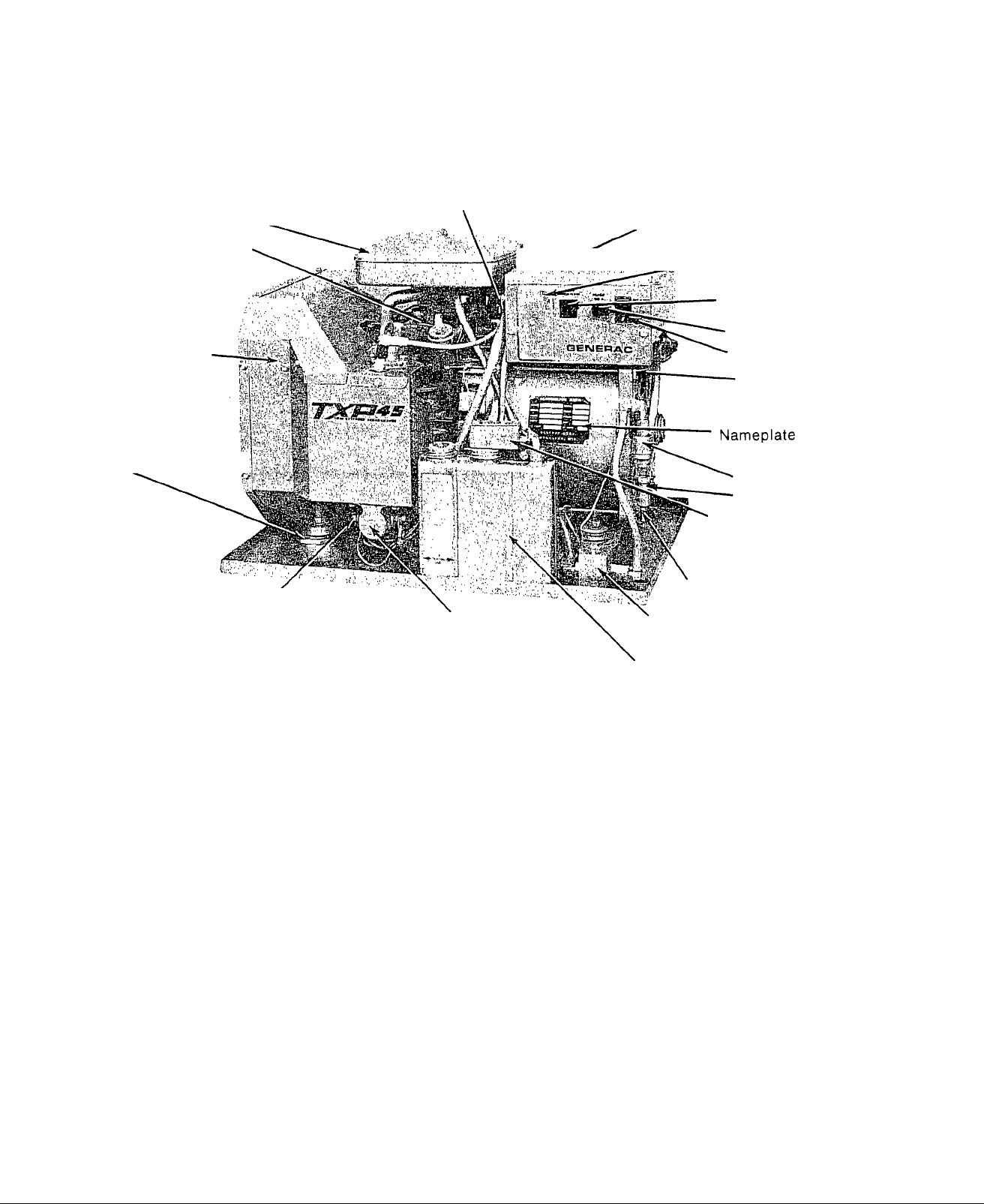
Engine Air Cleaner
Conduit Clamp
Button Plug
(Optional location of conduit clamp)
Oil Dipstick
Blower Shroud
Vibration Dampener
POSITIVE Battery
Cable Connection
Starter Solenoid
Figure 1. NOMENCLATURE
I Customer Wiring Connection
—■ Access Panel
Main Circuit Breaker
15 amp Fuse
Start/Stop Switch
NEGATIVE Battery
Cable Connection
Solenoid Operated
Fuel Shutoff Valve
Lowo7L¡^'""®'
Shutdown Switch
Customer Fuel Supply
Line Connection
Fuel Pump
Oil Make Up Tank
(2 quart)
Page 3

PART I
GENERAL
Section Title Page
1 Specifications.........................................................................................................................................................
Difference Data......................................................................................................................................................
Engine Lubrication................................................................................................................................................‘'■2
Electrical Test Specifications.............................................................................................................................. ■'•2
Torque Values........................................................................................................................................................‘'•2
Engine Specifications............................................................................................................................................
2 Wiring Diagram (Model 6931-0)............................................................................................................................2.1
Wiring Diagram......................................................................................................................................................2.2
Factory Equipped Customer Wiring Connections
TXP Reconnected for 120/240 Volt Output...........................................................................................................2.3
..........
...............................................................................
2.3
Page 4

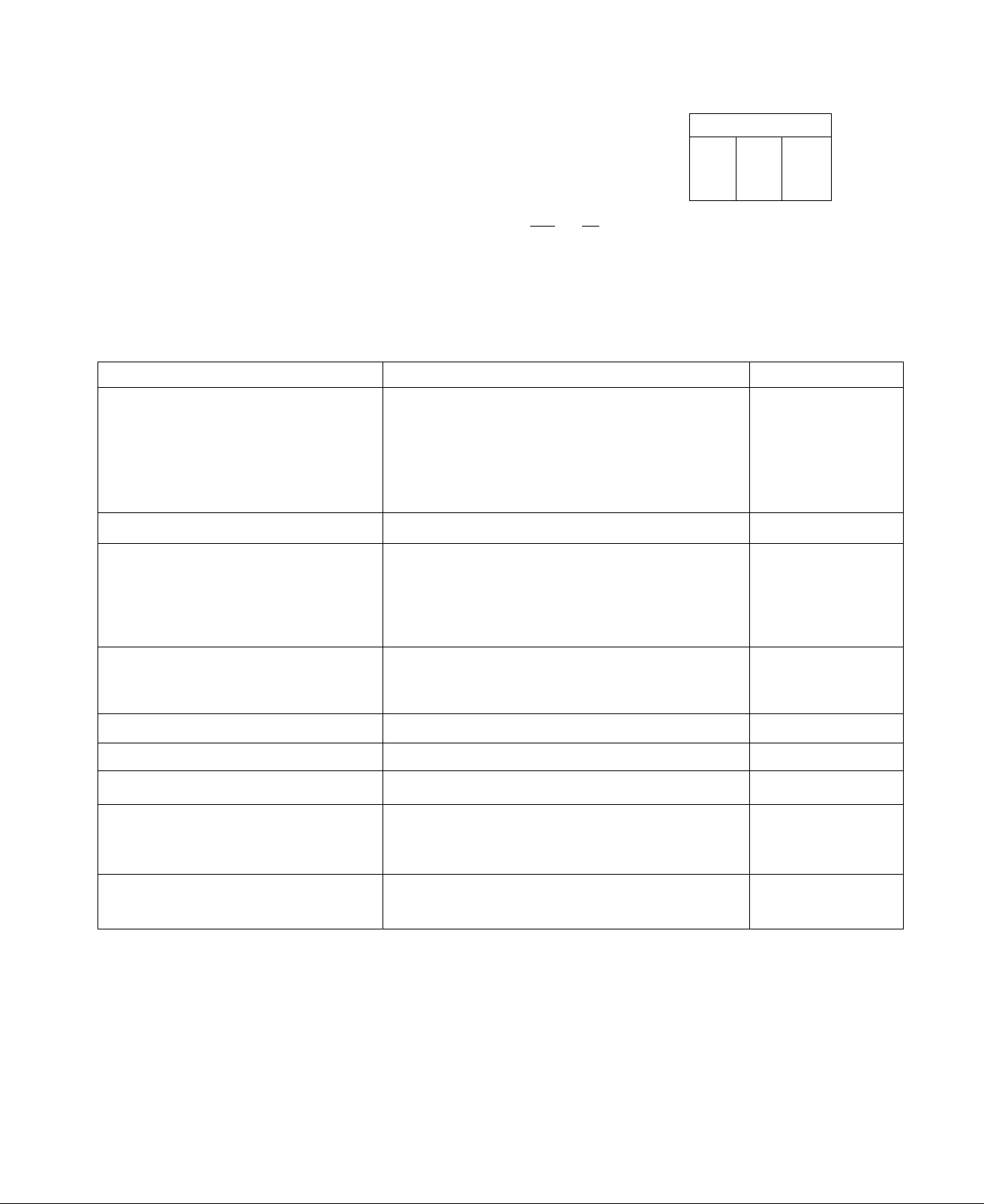
SPECIFICATIONS
Model No.
Wattage Capacity
Voltage Output
Amperes
Frequency
Phase(s)
Voltage Regulation
Driven Speed
Battery Charging
Amperes
Gross weight (wet)
Engine Type ■ ■
Engine Horsepower
Bore
Stroke
6931-0 6931-1 6931-2
4500
120/240*
37.5 at 120 Volts - 18.75 at 240 Volts
60 Hz
1-Phase
120 Volts ( + 27o) AC at 60 Hertz
1800 rpm
0-10 Amperes at 12 Volts DC
215 Pounds
2-Cylinder, 4-Cycle, Aluminum
Approximately 10 at 1800 rpm
3.44 Inches (87.3 mm)
2.16 Inches (54.7 mm)
Displacement
Valves
Stellite exhaust valves - Valve ro
tators on exhaust valves
40 Cu, In, (656 cc)
Governed Speed 1800 rpm
Air Cleaner
Crankcase Oil
Capacity
Oil Make-up System
Ignition System
Dry paper element, oil foam pre-cleaner
56 Ounces (3% Pints')
Maintains crankcase oil level at about
48 Ounces (3 Pints)
Solid state capacitor discharge type
Starting System 12 Volt DC electric (Ring Gear)
Cranking Current
Approximately 90 amperes nominal
*As shipped, alternator provides 120 volts AC only. Unit is
reconnectable to supply 120 and 240 volts AC. See Page 2,3.
DIFFERENCE DATA
Model 6931-0 - Rigid coupling between engine drive shaft and rotor
Model 6931-1 - Added a flexible coupling between engine drive shaft
___________________
and rotor
_________________________________________________________
Model 6931-2 t New rotor with improved 4-pole laminations. New im
proved blower housing with heavier sheet metal. New
_________________
improved inertia ring.with increased mass.
______________________________
Issued 6-78
1.1
Page 5
ENGINE LUBRICATION
Use any high quality detergent oil
having a classification which inc
ludes ’’Service MS, SC, SD or SE”,
No special additives should be used.
ELECTRICAL TEST SPECIFICATIONS
RECOMMENDED SAE VISCOSITY GRADES
1 1
100
60
°C-30
TEMPERATURE RANGE ANTICIPATED BEFORE NEXT OIL CHANGE
-20 10 10
80
30 40
20
*If not available, a synthetic oil may be used
having — 5W-20, 5W-30 or 5W-40 viscosity.
COMPONENT
Stator Windings
AC Power Windings
AC Power Windings
Excitation Windings
Battery Charge
Windings
Rotor
Ignition Stator
Charge Coil
Trigger Coil
Ignition Stator Voltage
Input to Printed
Circuit Board
Fuel Pump DC Resistance
Spark Timing
Choke Heater
TEST POINTS
Wire #11 - Wire #22
Wire #33 - Wire #44
White receptacle Pin #2 -Pin #6,
Wire #55 - Ground
Wire #77 - Ground
Brush terminals or Slip Rings
Ignition Module Receptacle Pin
#2 - Ground
Ignition Module Receptacle Pin
#3 - Ground
PGB Pin #4 - Ground
Fuel Pump terminal to ground
Wire #77 - Ground
TEST VALUE
0,42 Ohms
0,42 Ohms
2,30 Ohms
0,20 Ohms
0, 20 Olmns
13,00 Ohms
225.00 Ohms 4
6,00 Ohms
0.5-1.5 Volts
50,00 Ohms
26 BTDG
30.00 ohms
Sensing Transformer
Secondary Winding
Primary Winding
Field Boost Voltage
(While Cranking)
Wire #11 - Wire #22
White receptacle Pin #3 - #5
White receptacle Pin #4 - Ground
NOTE;-Either of two transformer makes may be used. The Wescoil transformer
has a primary winding resistance of 745-825 Ohms and a secondary winding
resistance of 1603-2169 Ohms, The CoilTran transformer has a primary resis
tance of 824-1114 Ohms and a secondary resistance of 1222-1654 Ohms.
1.2
See NOTE
See NOTE
9 - 12 VDG
Page 6

TORQUE VALUES
STANDARD TORQUE VALUES
Grade 2
BOLT SIZE
1/4-20 5 4
1/4-28
5/16-18 11 8
5/16-24
3/8-16
3/8-24 23 17 35
7/16-14
7/16-20
1/2-13
1/2-20 55 42
9/16-12
9/16-18 78
5/8-11
5/8-18
3/4-10
3/4-16
DRY LUB
6 5 10 7 12
13 10
20
32
36
49
70
92
105
165 125
180
1525
27
38
54 110 84
60 120
71
81
140 295
All Values in FOOT-POUNDS
TORQUE VALUES + 5 PER CENT
DRY
17 13 21
19 15 24
31
49 38
55
75
85 65 105
150
170
270 205
Grad
8
----------
LUB DRY
6
24
27
42
58
93 150 115
115 185 145
130 210 160
230
Grade 7
LUB
10
16
18
38 29
43
61
68
93 - 72
135 105
330
365
33
47
52 78
■ 80
250
280
Grade 8
DRY
8
9
27
49
105
120 90
155
170 132
210 165
240 185
375
420 320
■ LUB
12 9
14
24 18
44
70
11
21
34
38
54
60
82
120
290
7/8-9 200
7/8-14
1-8
1-14^ 340 260 680
SPECIAL TORQUES
Connecting Rod.
Cylinder Head (Torque in staggered.sequence)
Spark Plug.:.
Starter Motor Mounting Bolts..,i.............................................. .........................................160 In.-Lbs.
Engine Base
Sump (7 bolts)....
Crankcase Cover (7 bolts).
Governor Lever Lock Nut...,.
Fan to Engine Shaft Capscrew (Grade 5)-(Apply Loc^Tite
601 to capscrew threads:)
Flex Coupling to Rotor Hub Capscrews (Model 6931-2) -
(Apply LocTite 601 to capscrew, threads)................................................................. 19 Ft.-Lbs.
Flex Coupling to Fan Capscrews (Model 6931-2) - (Apply
LocTite 601 to capscrew threads).....................................................................................
.........
.....................................................................................................................
..............................
225 170 435 335
300
GRADE
BOLT HEAD
SYMBOL
.........
................................................ 200 In. -Lbs.
155 395 305 530
585 450
230
590 455
510
795 610
O
.
........................................................................••..190 In.-Lbs.
..................................
.(......I-............................................. 160 In.-Lbs.
.............................................................................
...........................................................................................
..................
..........
......................................................... 19 Ft.-Lbs.
..........
405
©
............
.......140 In.-Lbs.
605
670 515
905 695
..160 In.-Lbs.
300 In.-Lbs.
100 In.-Lbs.
19 Ft.-Lbs.
455
Issued 6-78 1»3
Page 7

ENGINE SPECIFICATIONS
Spark Plug Gap
Crankshaft End Play..
Governed Idle Speed Adjustment...............................................................................................
Valve Clearance (with springs installed)................................................................Intake .005"-. 007"
Valve Seat Angle...........................................................................................................Intake - .30
Valve Seat.Width...............................................................................................
Valve Seat Margin................................................................................................Not less than 1/64'
Valve Clearance (springs not installed).,......
Crankshaft Reject Sizes.........................................................................................PTO Journal 1.376'
Cylinder Boi'e Standard Diameter
Ring Gap Reject Sizes (Top and center compression)......................................................................0.035'
Ring to Ring Groove Maximum Clearance
Maximum Piston Pin Out-of-Roundness....................................................................................,0,0005'
Crankpin Bearing Hole Rejection Size........................................................................................
Piston Pin Bearing Hole Rejection Size...;,.......................................................,,,,.,.,,.....0,802'
Camshaft Rejection Sizes (Gear and. Shaft Journals).......................................................................0,623'
Cylinder Bore Maximum Out-of-Roundness,
Cylinder Bore Oversizes when honing..........................................................
..................................................................................................................................
.............................................................................................
.........................................................
...................................................................................
(oil Ring)................................................................................ .......0.045'
........................................................................................
(Cam Lobes)
.........................................................................
.........................................................................0,0025'
........
0.002"-0.008"
1400 rpm*
Exhaust .007"-.009"
Exhaust - 45
...................
Intake .007"-.009'
0,010" above standard
0.020" above standard
0.030" above standard
3/64"- 1/16’
Exhaust ,009"-.Oil'
Crankpins 1.622'
..... 3.4375**
...1.252'
0.030"
0.007'
1.124'
*Adjust carburetor idle screw to 900 rpm
**Resize if worn 0.003" or more
1.4
Issued 6-78
Page 8
CM
(O
s
<
oc
(3
<
o
CD
z
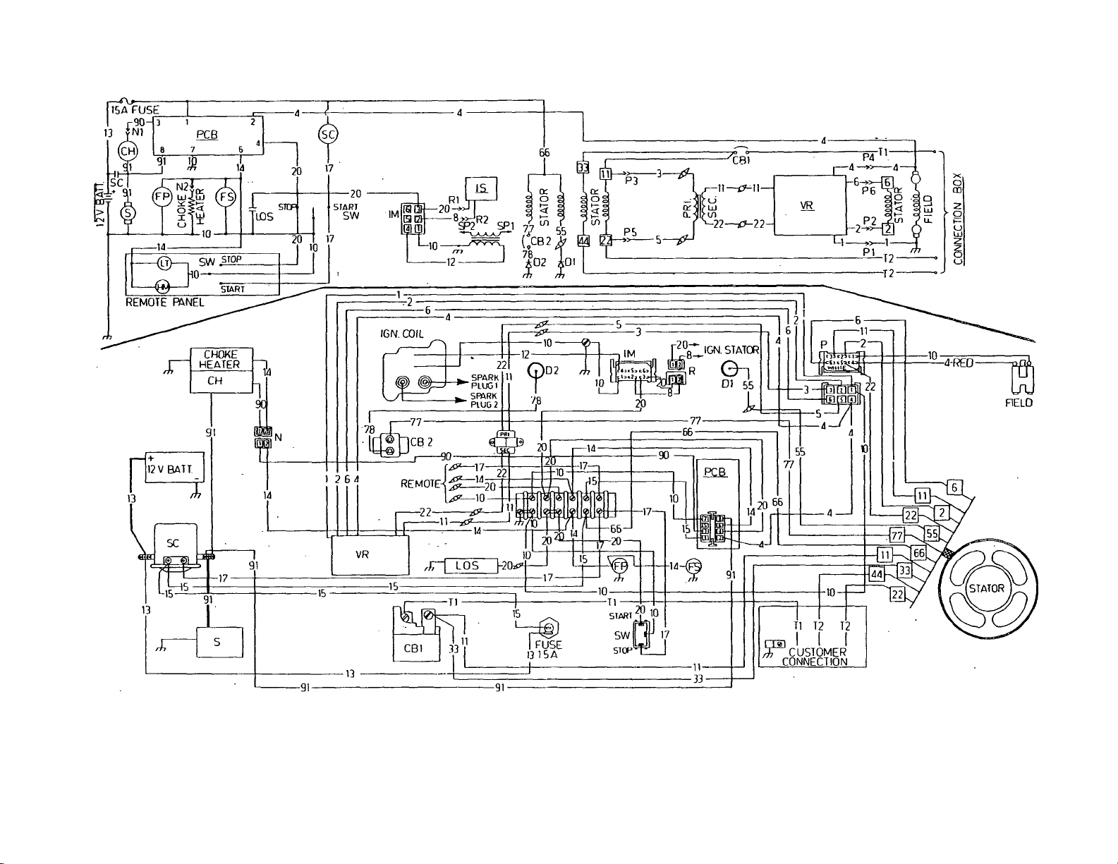
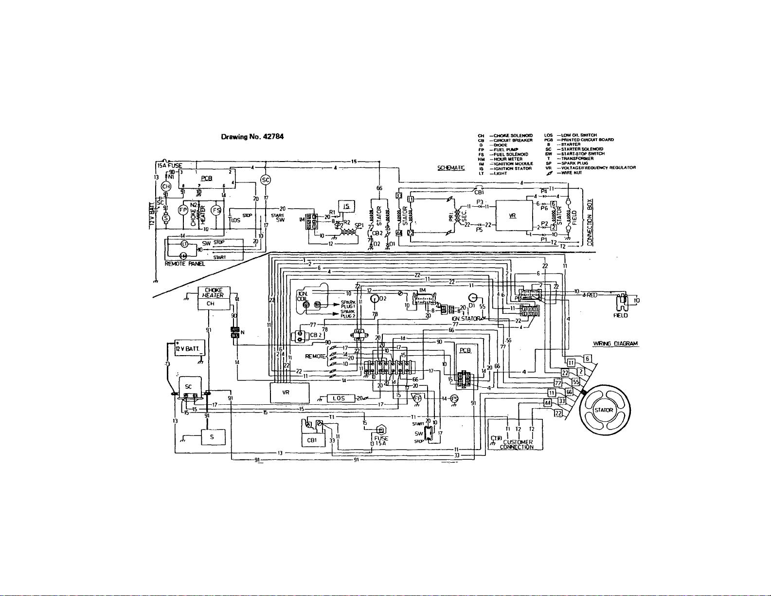
SCHEMATIC
tH
I
CNJ
WIRING DIAGRAM
E
MODEL 6931 -0
legend
CH~ cnoke So/enold
CB— Circuit Breaker
D— Diode
PP— Fuel. Pump
FS— Fuel Solenoid
HM— Hour Meter
IM— Ignition Module
IS— Ignition Stator
UT— Light
LOS— Low Oil Switch
FCB— Printec? Circuit Board
S— Starter
SC— Starter Solenoid
SW— Start-Stop Switch
T— Transformer
SP— Spark Plug
VR— Voltage/Frequency Regulator
^ — Wire Nut
WIRING DIAGRAM
00
CO
X)
0)
. d
CO
CO
I
Page 9
ro
to
WIRING DIAGRAM
W
in
0
0)
a-
OJ
■o
oo
I
MODEL 6931-1
6931-2
)
),
Page 10
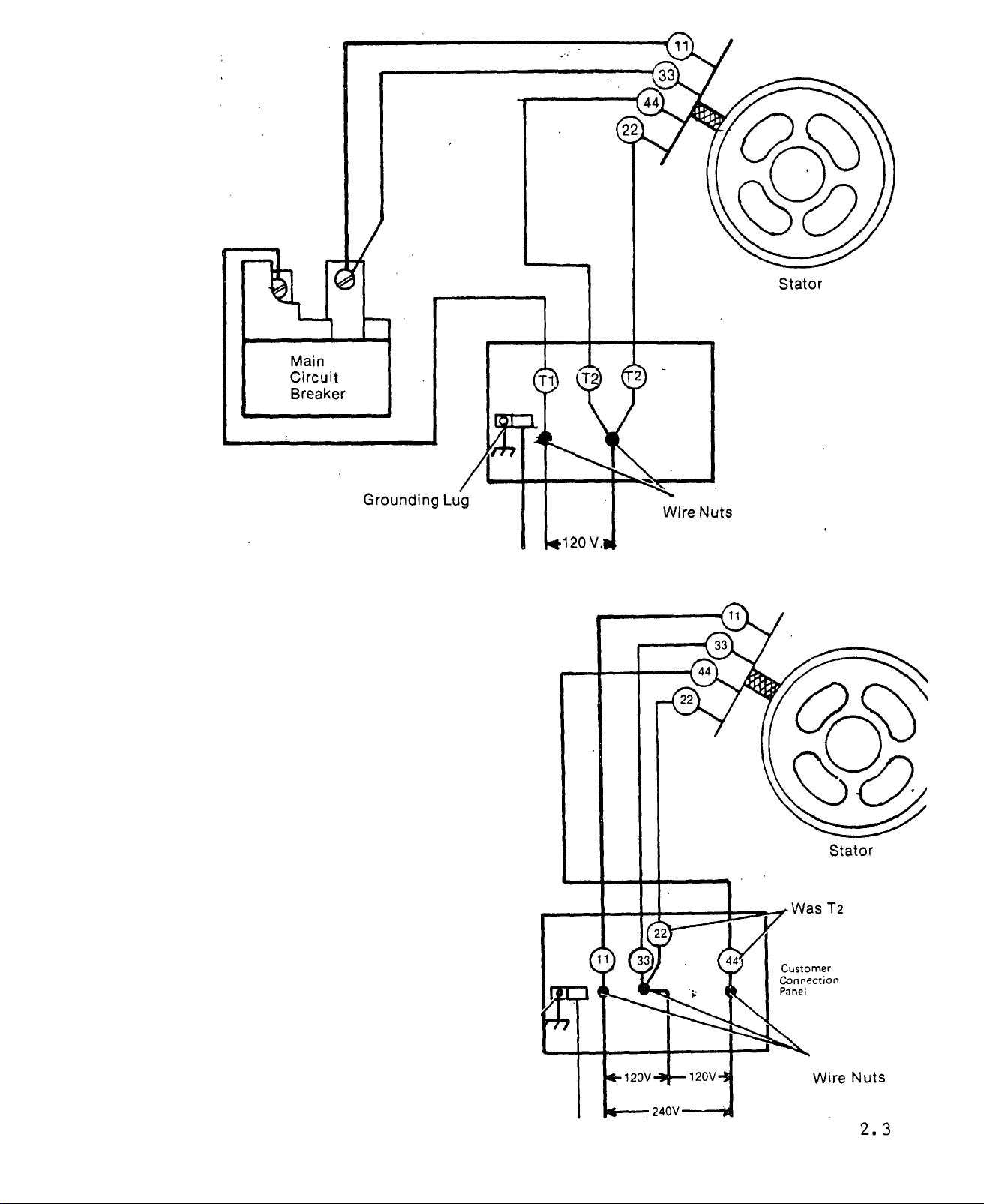
Factory Equipped Customer Wiring Connections
120VoitsOniy
PROCEDURE
1. Disconnect wires No. 11 and No. 33 at
main circuit breaker,
2. Disconnect wire No. Ti at main cir
cuit breaker and discard.
3. Route wires No. 11 and 33 (discon
nected from main circuit breaker) to
customer connection panel.
4. Connect customer wiring as shown
to obtain both 120 and 240 volts A-C.
XR
Main
Circuit
Breaker
Main Circuit Breaker is Not Connected
TXP RECONNECTED FOR 120/240 VOLT OUTPUT
Issued 3-78
Grounding Lug
Page 11

PART II
TROUBLE DIAGNOSIS
Section Title Page
3 DIAGNOSTIC FLOW CHARTS
Engine Won’t Crank....................................................................................................................3.1
Engine Cranks, Won’t Start.........................................................................................................3.2
Engine Starts Hard, Runs Rough............................................................................................... 3.5
Switch Set to STOP, Engine Keeps Running..............................................................................3.7
A-C Voltage Low..........................................................................................................................3.8
A-C Power Low............................................................................................................................3.9
A-C Voltage High.........................................................................................................................3.9
No A-C Voltage..........................................................................................................................3.10
4 DIAGNOSTIC TESTS
Test 1-15 Amp Fuse..................................................................................................................4.1
Test 2 - Battery............................................................................................................................4.1
Test 3 - Start/Stop Switch............................................................................................................4.2
Test 4 - Starter Solenoid
Test 5 • Starter Motor...................................................................................................................4.4
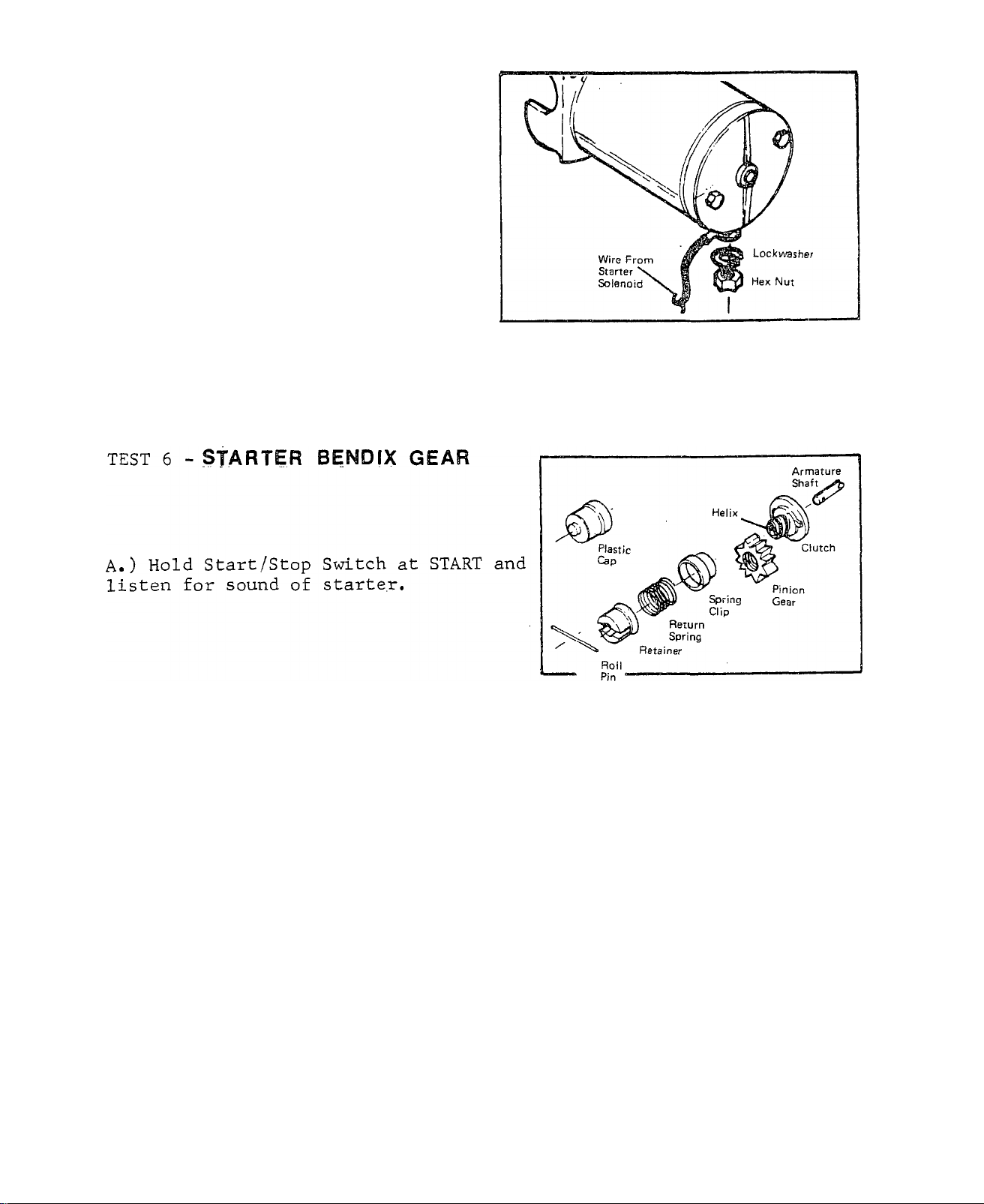
Test 6 - Starter Bendix Gear........................................................................................................4.4
Test 7 - Starter Ring Gear............................................................................................................4.5
Test 8 - Check Spark...................................................................................................................4.5
Test 9 - Oil Make-up Tank...........................................................................................................4.6
Test 10 - Low Oil Switch..............................................................................................................4.6
Test 11 - Spark Plug....................................................................................................................4.7
Test 12 - Ignition Module.............................................................................................................4.7
Test 13 - Ignition Stator................................................................................................................4.8
Test 14 - ignition Coil...................................................................................................................4.8
Test 15 - Low Fuel Level..............................................................................................................4.9
Test 16 - No Fuel Flow...............................................................................................................4.10
Test 17 - 4 Amp Fuse.................................................................................................................4.10
Test 18 - Printed Circuit Board....................................................................................................4.11
Test 19- Fuel Filter.....................................................................................................................4.11
Test 20 - Fuel Shutoff Solenoid.................................................................................................4.12
Test 21 - Fuel Pump...................................................................................................................4.12
Test 22 - Check Installation........................................................................................................4.13
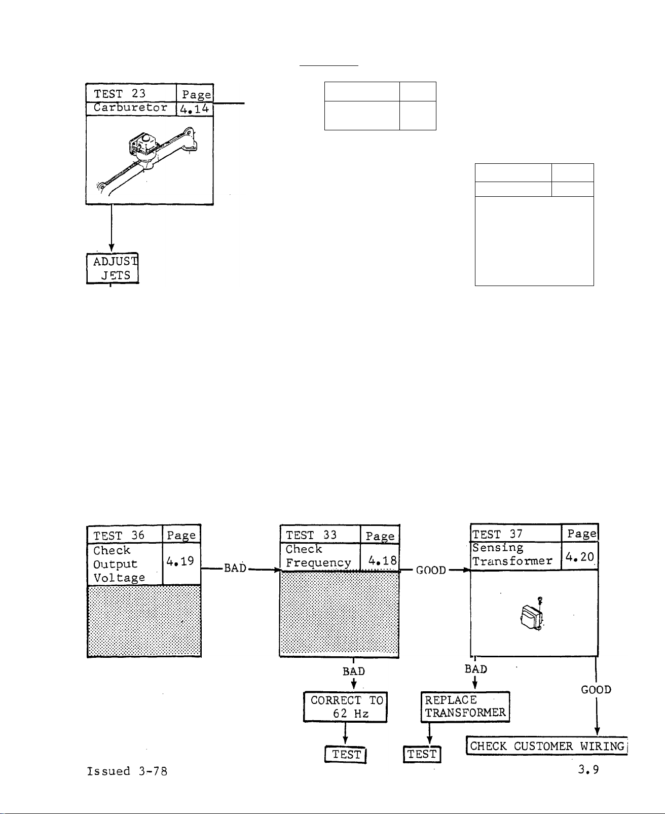
Test 23 - Carburetor...................................................................................................................4.14
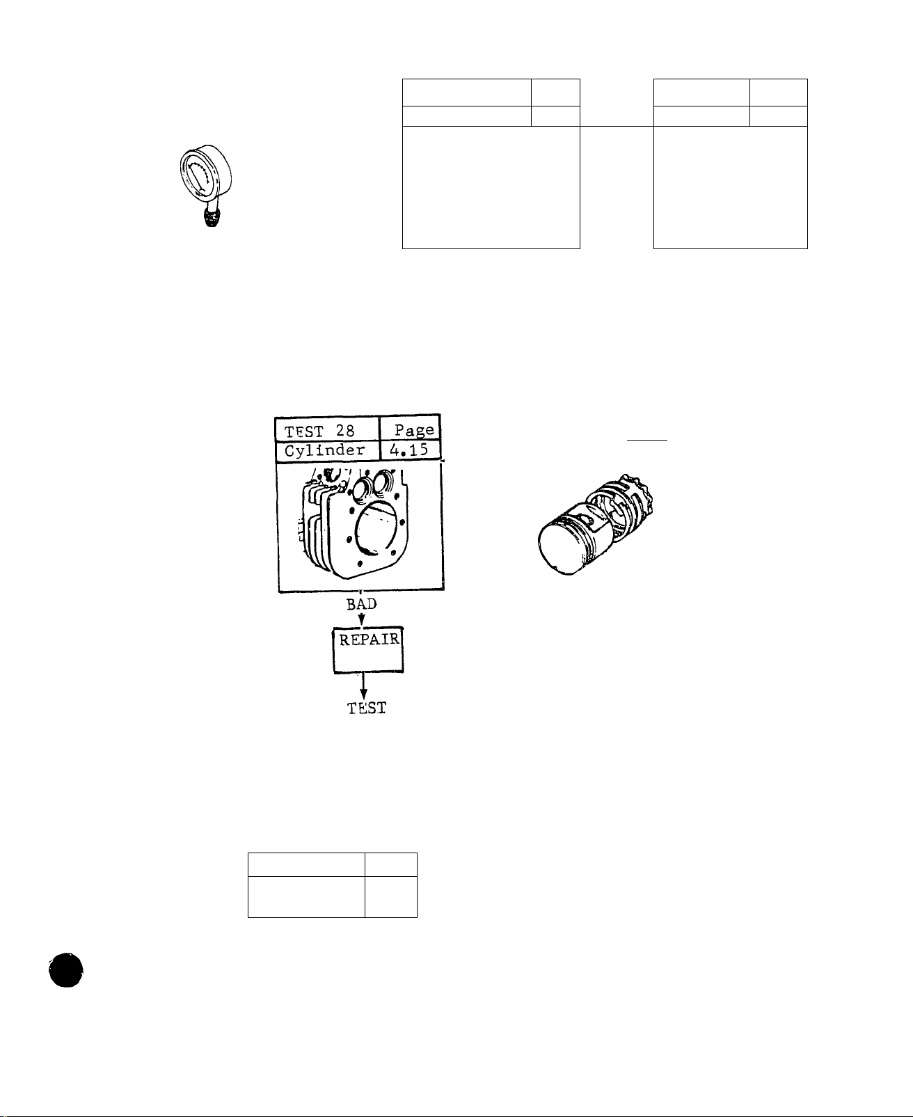
Test 24 - Compression...............................................................................................................4.15
Test 25 - Head Gasket...............................................................................................................4.15
Test 26 - Valves.........................................................................................................................4.15
Test 27 - Rings...........................................................................................................................4.15
Test 28 - Cylinder.......................................................................................................................4.15
Test 30 - Choke..........................................................................................................................4.16
Test 31 - Pre-Choke...................................................................................................................4.17
Test 32 - Governor.....................................................................................................................4.17
Test 33 - Frequency...................................................................................................................4.18
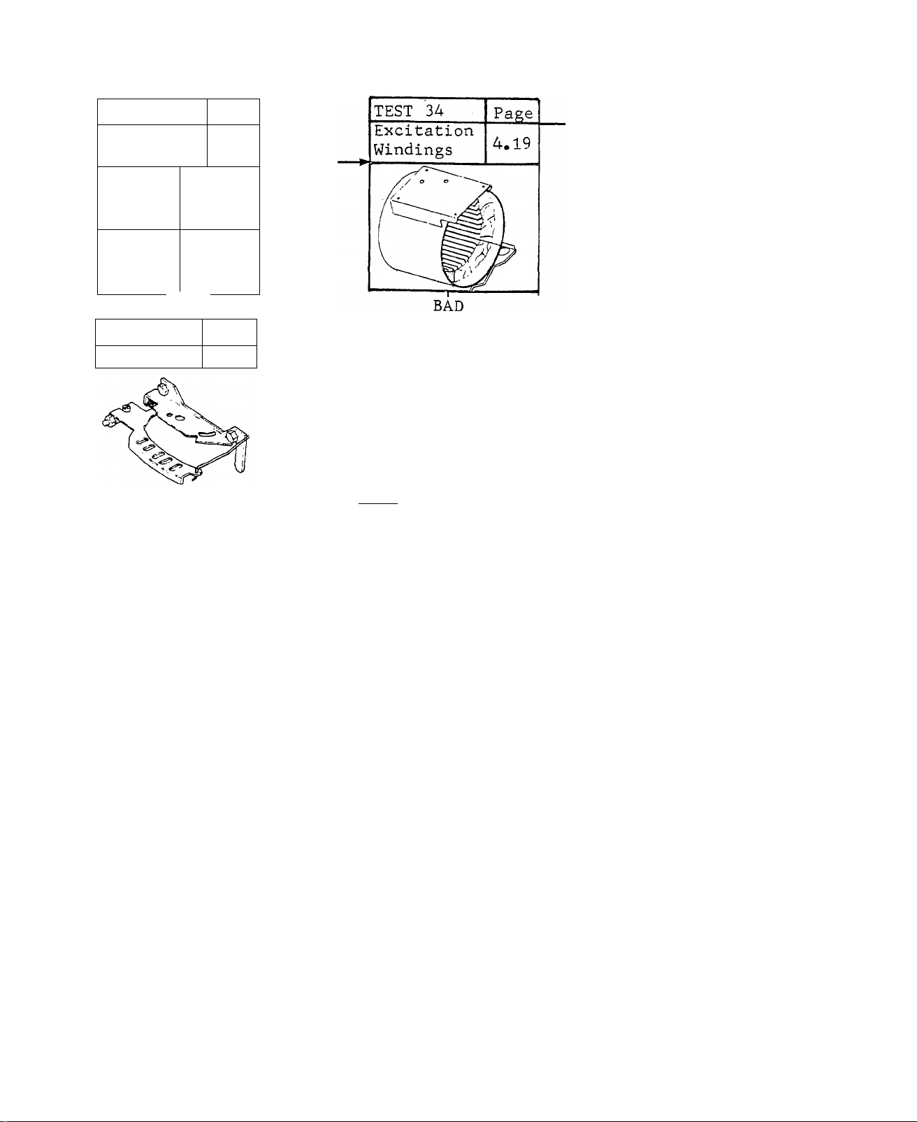
Test 34 - Excitation Windings.....................................................................................................4.19
Test 35 - Carbon Buildup...........................................................................................................4.19
Test 36 - Cutput Voltage............................................................................................................4.19
Test 37 - Sensing Transformer
Test 38 - Main Circuit Breaker...................................................................................................4.21
Test 39 - Rotor...........................................................................................................................4.21
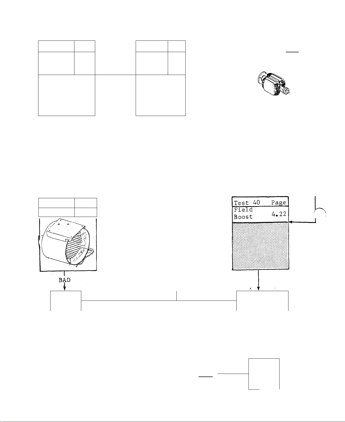
Test 40 - Field Boost..................................................................................................................4.22
Test 41 - Stator...........................................................................................................................4.23
Test 42 - Charging Cutput..........................................................................................................4.23
Test 43 - Circuit Breaker........................................................................................................... 4.24
Test 44 - Diodes D1 and D2.......................................................................................................4.24
Test 45 - Stator Battery Charge Windings..................................................................................4.25
................................
..................................................................................................
'..............................................................................4.3
4.20
Page 12
DIAGNOSTIG FLOW CHARTS 3
IMTRODUCTION
Use these FLOW CHARTS in conjunction with the detailed instructions for
each test in Section 4, Test numbers assigned In the FLOW CHART are id
entical to the test numbers assigned to specific tests in Section 4.
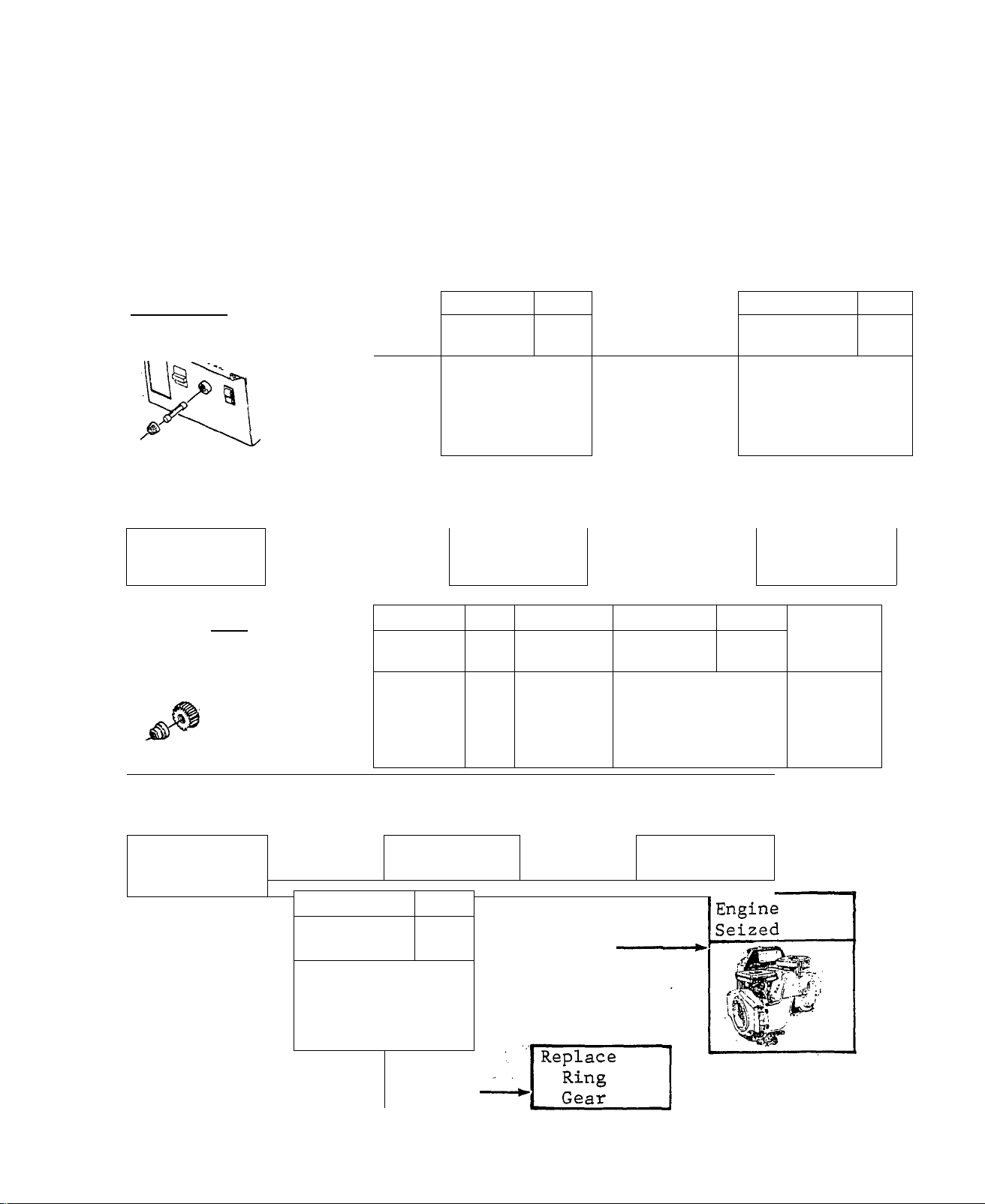
ENGINE WON’T CRANK
TEST 1 Page
15 Amp
Fuse
-------1-------
CHECKS
BAD
f
Replace
Fuse
TEST 6
Starter
Bendix
Gear
«i^'^Retalner
Pin
Gear
CHECKS
BAD
t
Replace
Bendix
Gear
CHECKS'
GOOD
Page
4.4
Clutch
4.1
CHECKS
GOOD
CHECKS
■ GOOD
Test 7
Starter
Ring Gear
TEST 2 Page
Battery
4.1
■ CHECKS
GOOD
CHECKS
BAD
Recharge or
Replace
TEST 5 Page
STARTER
4.4
MOTOR
CHECKS
TEST 4
Starter
Solenoid
GOOD
CHECKS
CHECKS
BAD
1
Replace Replace
Motor
Solenoid
Page
4.5
CHECKS
GOOD
BAD
t
TEST 3
Page
4.3
Start/Stop
Switch
CHECKS
BAD
Replace
Switch
^CHECKS
GOOD
Paee
4.2
Issued 3-78
CHECKS
BAD
3.1
Page 13
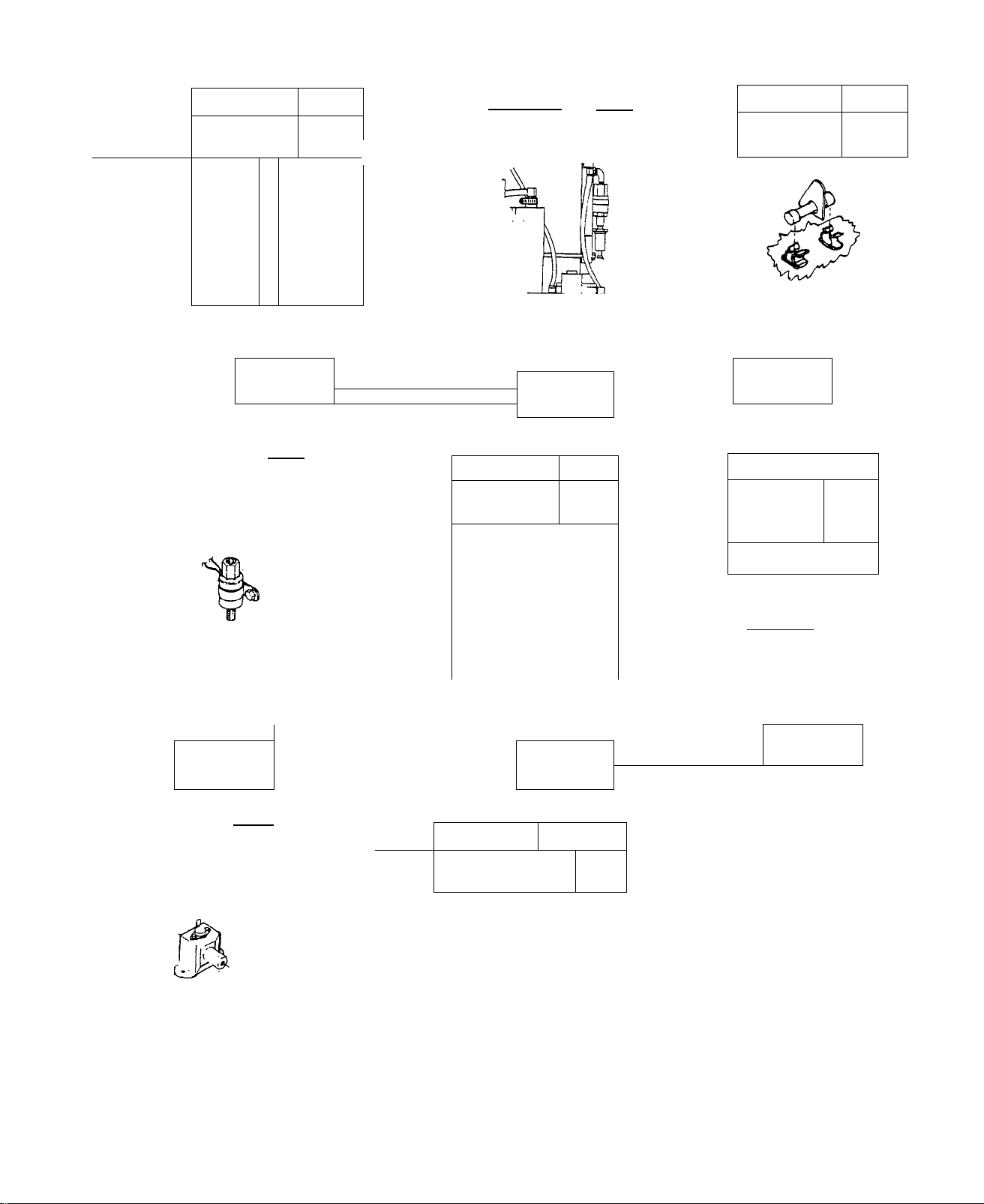
ENGINE CRANKS , WON’T START
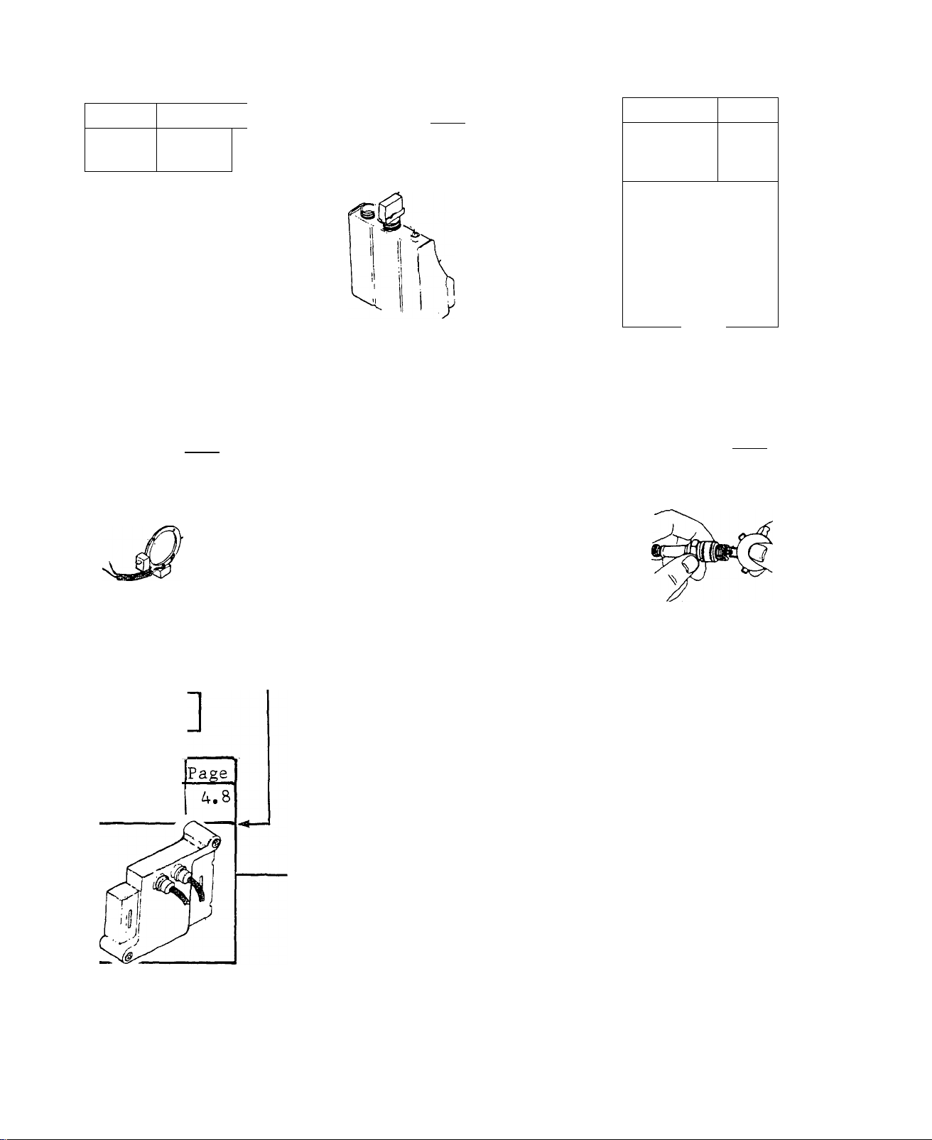
TEST 8 Page
Check
Spark
TEST 13
Ignition
Stator
4.5
Page
4.8
NO
SPARK
•GOOD-
TEST 9
Oil
Make-Up
Tank
TEST 12
Ignition
Module
LOW
FILL
TANK
Page
4.6
—GOOD
4.7
-------
-GOOD-
TEST 10
Low Oil
Switch 4.6
Page
4
BAD
I
REPAIR/
REPLACE
TEST 11
Spark
Plug
Page
4.7
GOOD
BAD
__L
Replace
Stator
TEST 14
Ignition
Coil
GOOD
BAD
BAD
I
Replace
Module
[Replace
Coil
^jlF SPARK CHECKS GOOD,«
^ GO TO TEST 15 3
BAD
Replace
Plug
3.2
Issued 3-78
Page 14
______________________
TEST 15
Low Fuel
Level
.
To Vthicii
Engintf
Page
To Alternitor
Engine
4.9
— GOOD
TEST 16
No Fuel
Flow
Page
4.10
-BAD
TEST 17
4 Amp
Fuse
Page
4.10
___________
TEST 20
Fuel
Shutoff
Solenoid
Fuel ^
T«ik В
FILL
TANK
S ^‘Pe
Д Nipple
^<^Anti ■ Siphon
Holes
LOW
i
Page
4.12
Pipe Cep
■GOOD.
TEST 19
Fuel
Filter
”F“
GOOD
GO TO
TEST 23
Page
4.11
-.GOOD
BAD
I
REPLACE
FUSE
TEST 18
Printed
Circuit
Board
и ~ c=3 p|n
GOOD
Page
4.11
GOOD
REPLACE
SOLENOID
TEST 21
Fuel
Pump
BAD
Page.
4.12
GOOD.
■ BAD-
------------------
TEST 22
Check
Installation
,| REPLACE
BAD
REPLACE
FILTER
PUMP
1
—I—
BAD
REPLACE
BOARD
Page
4.13
SIF TEST 1.6 IS GOOD,t
3 GO TO TEST 23 (
Issued 3-18 3.3
Page 15
TEST 23
Carburetor
J / ^
Page
4.14
TEST 24
COMPRESSION
Page
4.15
BAD
TEST
GOOD
REPLACE
GASKET
ADJUST
JETS
’
FLOAT
SEAT
FLOAT
LEVEL [
-BAD J replace
|. SEAT
1
hBAD-
NO
■ CHANGE’
I adjust"
'I FLOAT.
-8^,TEST
REPIACE
CARBURETOR
TEST
,1 TEST
BAD
1 TEST
TEST 26
VALVES
1
-------
TEST.
TEST 28
CYLINDER t4.15
1 REPAIR 1
_Page_
Page
4.15
3.4
T.EST.
TEST 27
RINGS
h:
Page
4.15
REPLACE I
GOOD
■ GOOD
GOOD
-»‘I GO TO TEST 29§i
_ - --
_ - .
Issued 3-78
Page 16
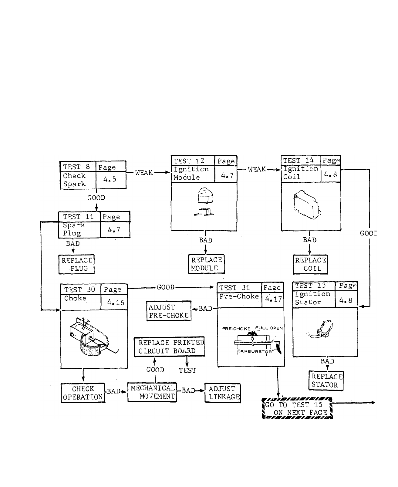
ENGINE STARTS HARD - RUNS ROUGH
Issued 6-78
3.5
Page 17
TEST 15.
Low Fuel
Level
Page
4.9
■ GOOD
TEST 16 Page
Fuel Flow
4.10
BAD
-GOOD-
TEST 23
Carburetor
Page
4.14
TEST-^
TEST-*-
FILL
TANK
REPLACE
FILTER
REPLACE
SOLENOID
TEST 19
Fuel
Filter
TEST 20
Fuel
Shutoff
Solenoid
Page
4.11
9
[adjustI
Ijets
BAD^
REPLACE
CARBURETOR
-TEST
CHECK
REPLACE
SEAT
-TEST
Page
FLOAT
VALVE
■ BAD*.
4.12
ADJUST
FLOAT
-TEST,
1 ■
FLOAT
LEVEL BAD-^
TEST-*-
3.6
REPLACE
PUMP
TEST 21
Fuel
Pump
TEST 22
check
Installation
Pagè
4.12
Page
4.13
TEST 32
Gove mor
"^8 COMPRESSION "
Page
4.17
’change'
BAD
I
ADJUST
GOVERNOR
5 GO TO TEST 24 I
Issued 3-78
NO
Page 18
TEST 24
Compression
-—BAD
TEST 25 .
Head Gasket
Page
4,15
TEST 26
Valves
Page
4.15
BAD
REFI ACE
GASKET
TEST
GOOD-
TEST 27
Rings
REELAGEl
R-INGS
BAD
GOOD
REPAIR
''
TEST
Page
4.15
BAD
1
Issued 6-78
TEST.
SWITCH SET TO STOP - ENGINE KEEPS RUNNING
TEST 3
Start/Stop
Switch
Page
4.2
-BAD
I REPLACE
■ *" SWITCH
3.7
Page 19
A-C VOLTAGE LOW
TEST 33
Check
Frequency
BAD
TEST 32 Page
Governor
Page
4.18
4.17
■ GOOD
¡testI
REPLACE
STATOR
■ GOOD-
REPLACE VOLTAGE
REGULATOR
3.8
Issued 6-7 8
Page 20
A-C POWER LOW
GOOD
T
TEST
NO .
■ CHANGE'
TEST 35
Page
Carbon
Build-up
.4.19
DE-CARBONIZE
- HEAD
TEST
NO
CHANGE
NO ‘
-CHANGE-
TEST 32
Governor
(^
Page
4.17
sf^ ^
TEST
A-C VOLTAGE HIGH
Page 21
NO A-C voltage,
TEST 36
Page
Cheek
Output
4.19
Voltage
GOOD
I
CHECK CUSTOMER
WIRING
TEST
TEST 38
Main
Circuit
Breaker
BAD
REPLACE
CIRCUIT
BREAKER
~T~
TEST
Page
TEST 29
Rotor
Page
4.21
4.21
-GOOD■
BAD.
I
REPLACE
ROTOR
TEST
GOOD
TEST 41
Stator
REPLACE
STATOR
TEST.
Page
4.23
GOOD
CHECK WIRE
#14 '
[testI-
-BAD.
CHECK VOLTAGE
TO ROTOR
------------1------------BAD
_L_
CHECK #4 WIRE
FOR 12 VOLTS'
-----------
1
----------------
GOOD
I
REPLACE
PRINTED
CIRCUIT
BOARD
3.10
Issued 3-78
Page 22
DIAGNOSTIC TESTS
TEST 1 - l.S.AMP -FUSE
Remove and visually inspect the 15
amp fuse. A more thorough check may
be made with a Volt-Ohm-Milliammeter,
a_s foil o\vs :
1. Set VOM to ''+nC" and to ”Rxl”
scale.
2. Connect test probes together and
’’Zero" the meter.
3. Touch test probes to the fuse
ends - meter needle should swing up
scale and indicate "Zero” ohms. If
needle does not move upscale, replace
the fuse.
RESULTS: 1.) Fuse tests bad.............Install new 15 Amp Fuse
2.) Fuse tests good
...............................
.....Continue tests in "Diagnostic
4
Flow Charts", Section 3
TEST 2 - BATTERY
Check battery condition, as well as
the condition, cleanliness and sec
urity of battery cables and.connec
tions.
RESULTS: 1.) Battery, cables or connections
test bad.......................................
2.) Battery, cables and connections
test good
..................................................
.....Replace or repair the defec
tive component
Continue tests in "Diagnostic
Flow Charts", Section 3
Issued 3-78
4.1
Page 23
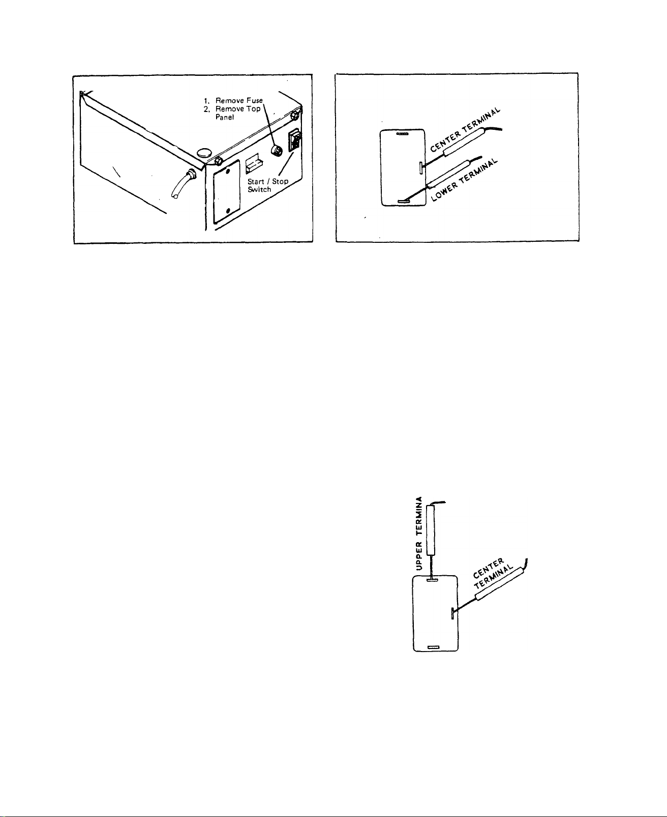
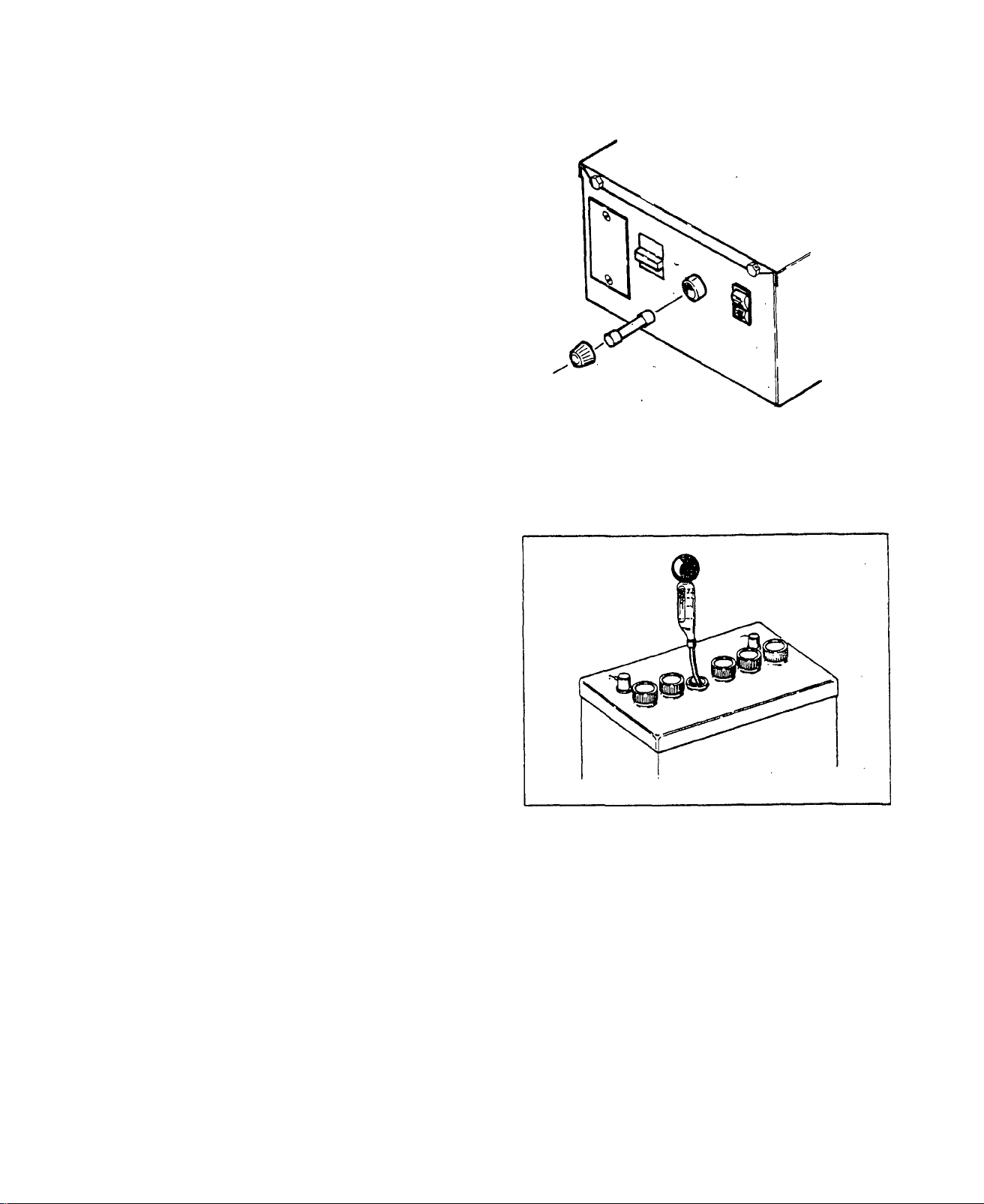
TEST 3 -START - STOP SWITCH
/^5
Remove the 15 amp Fuse to disconn
ect the starting circuit. Then re
move 2 screws that retain the top
panel. Finally, remove the top
panel.
RESULTS: 1.) Switch tests Bad..
2.) Switch tests Good.
Connect the VOM test probes to the
Switch terminals as shown at right.
Hold Start./Stop Switch at START meter needle should not move.
Set the switches of a Volt-Ohm-
Milliammeter to and to ''Rxl"
scale. Connect meter test probes
together and ”Zero" the meter.
Connect the meter test.probes to
the switch center and lower termi
nals, as shown above. Meter needle
should not move. Hold Switch at
STA.RT position - meter needle
should, move upscale, to "zero”.
Hold switch at STOP - meter needle
should drop all the way downscale
to "Infinity”.
.
......................
......................
Install a new switch
Continue tests
Release the Switch to NEUTRAL po
sition - the meter needle, should
not move.
Hold the Switch at STOP - the. meter
needle should swing upscale and. ind'
icate "zero" ohms.
RESULTS: 1.) Switch tests Bad..
2.) Switch tests Good.
4.2
.Install a new Sta.rt/Stop Switch
.Reconnect wires to Switch
Install top panel
Install 15 Amp Fuse
Continue Tests
Issued 3-78
Page 24
TES T 4 - STARTER SOLENOID
A.) Set the Start/Stop Switch to
START position and back to NEUTRAL
several times. An audible "click”
should be heard as the solenoid
actuates^
RESULTS: !.) Solenoid actuates, but
engine does not crank
...............................
Continue- ttst (Paragraph "B")
2.) Solenoid does not actuate,..Continue test (Paragraph "D")
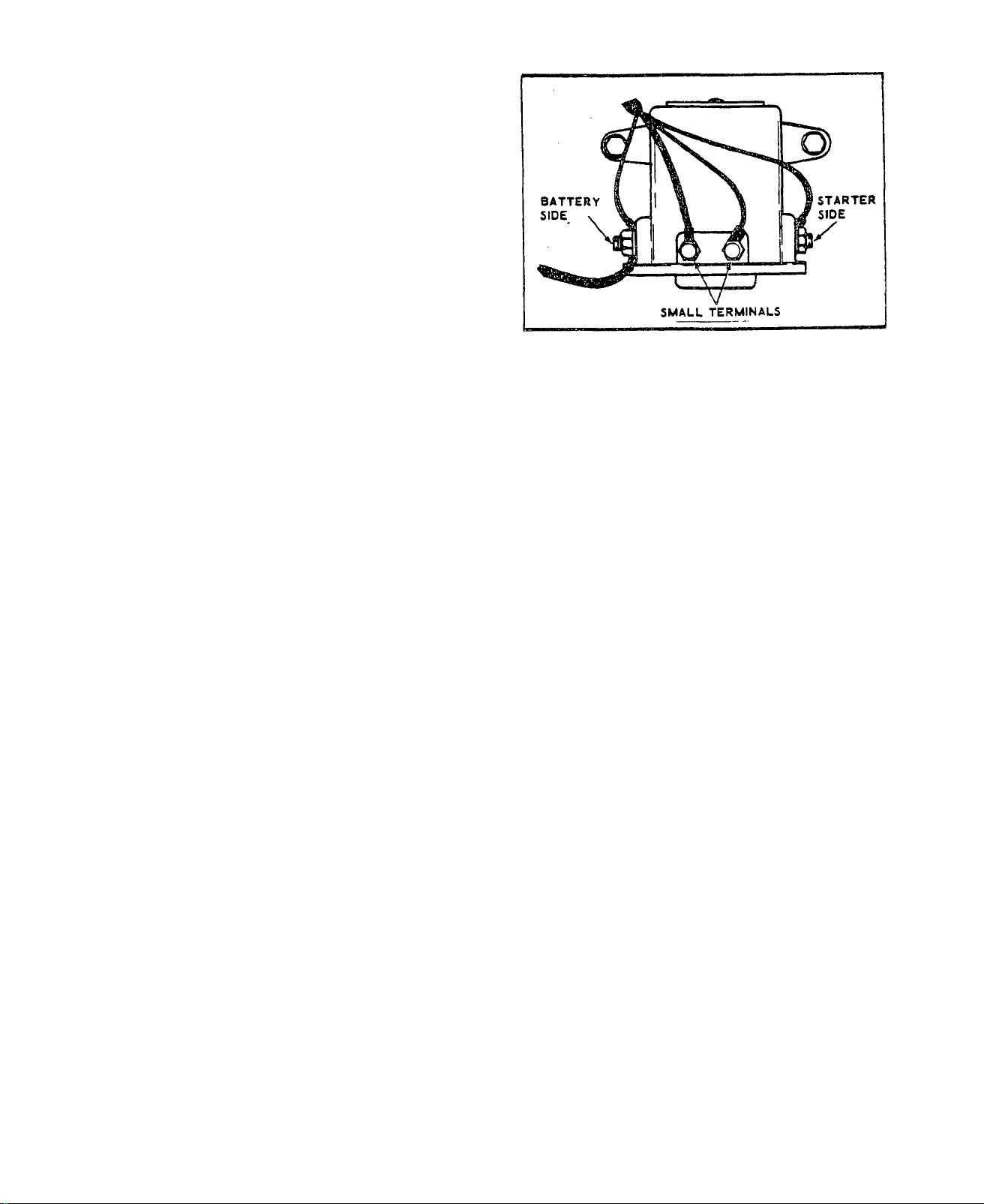
B. ) Set VOM to "+DC" and to a scale greater than 12 Volts DC. Connect
the NEGATIVE (pr COMMON) test probe to. ground. Connect the POSITIVE (+)
test probe to the battery cable connection on the starter solenoid. The
meter needle should indicate 12 volts DC.
RESULTS: 1.) Meter reads 12 VoltsContinue test (Paragraph "C")
2.) Meter indicates less
than 12 Volts..............................................Check for open or shorted wire
or loose connections between
battery and starter solenoid
C. ) Connect POSITIVE (+) meter probe to starter cable connection on
starter solenoid. Connect NEGATIVE (or COMMON) test probe to ground.
Hold Start/Stop Switch at START - meter should indicate 12 volts DC.
RESULTS: 1.) Meter does not indicate
12 Volts...............................................
..Install new starter solenoid
2.) Meter reads 12 Volts and
solenoid checks good.......Continue tests in "Diagnostic
Flow Charts", Section 3
D. ) Set VOM to "+DC" so that 12 Volts can be read. Connect, meter POS
ITIVE (+) probe to one of the small terminals on the starter solenoid.
Connect the remaining test probe to ground. Meter should read.12. Volts.
With NEGATIVE (or COMMON) test probe still connected to ground, conn
ect POSITIVE (+) test probe to the other small terminal. Meter should
indicate 12 volts DC.
RESULTS.: 1.) Meter indicates 12. Volts
from BOTH small terminals
to ground
.............
Continue tests in. "Diagnostic
Flow Charts", Section 3
Meter does NOT read 12
2.)
Volts.........................................................Retest battery, 15 Amp Fuse
and Start/Stop Switch. Wlien
sure that these components
are good, and 12 volts is not
obtained from both small ter
minals, replace solenoid,
Issued 3-78
4.3
Page 25
TEST 5 - STARTED MOTOR
A.) Set VOM to ”+DC" and to a high
enough DC volts scale to permit
reading 12 volts. Connect the POS
ITIVE test probe to starter cable
connection at the starter. Connect
the NEGATIVE (or COMMON) test lead
to ground,then hold Start/Stop
Switch at START. Starter should
run and meter should read 12 Volts.
RESULTS: 1.) Meter, indicates .12.. Volts,
■ but starter does not run...... Replace starter
2.) Starter runs........................................................Continue tests in "Diagnostic
Flow Charts", Section 3
RESULTS: 1.) Starter motor can be heard
running without load,
L'OOCAOOOOO .Continue checks in Paragraph
IfRtt
'B
2.) Starter runs and cranks the
engine
.....................................................
...Continue tests in. "Diagnostic
Flow Charts", Section 3
B. ) Remove starter. Inspect pinion gear for damage or excessive wear,
RESULTS: 1.) Starter pinion gear damaged,
..................................................
2.) Starter Pinion gear is good,.................................................Continue test (Para
C. ) Without installing starter, connect starter cable from starter sol
enoid to starter terminal post. Hold Start/Stop Switch at START. The
starter pinion gear should move outward on the clutch.
4.4
Replace
graph C)
Issued 3-78
Page 26
RESULTS: 1.) Starter Pinion Gear does
not move outward.............................
2.) Pinion Gear does move out
ward.’
..................................................
TEST 7 - STARTER RING GEAR
A.) Inspect Starter Ring Gear for
damaged teeth.
.
.
Inspect helix on clutch for
freedom of operation. If
sticking due to dirt, clean
entire starter drive. If
any parts are damaged or
worn, replace.
.Continue tests in ’’Diagnos
tic Flow Charts", Section 3
RESULT: 1.^ Ring. Gear damaged,
2.) Ring Gear Good....
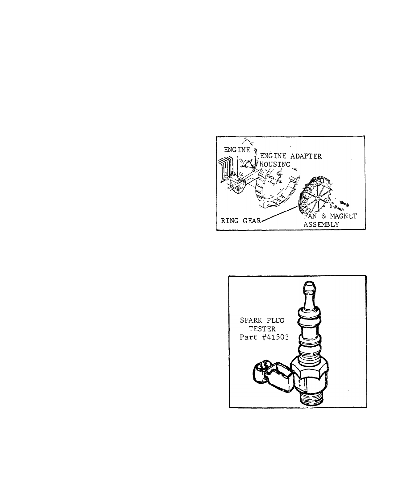
TEST 8 -CHECK SPARK
A.) Remove lead from one spark plug.
Connect the lead to Spark Plug test-
er,
plug tester clamp to a clean, paint-
free ground. Crank the engine - a
sharp, "snappy" spark should be seen.
Repeat the test for the remaining
spark plug. _______________________
NEVER crank the engine, with a spark
plug or spark plug lead removed, un
less the spark plug or.lead Is conn
ected to a clean ground. Failure to
ground the plug or lead can damag.e.
the ignition coil. _______________________________
Part No. 41503. Attach the spark
^CAUTION
.Replace
.Continue tests in "Diagnostic
Flow Chart", Section 3
RESULT: 1,)A sharp, snappy spark is NOT
observed...
2.)A sharp, snappy spark is ob
served.
........
...........................................
.....
..................................................
Issued 3-78
.Continue tests in "Diagnostic
Flow Charts", Section 3
.Continue tests in "Diagnostic
Flow Charts", Section 3 4^5
Page 27
TEST 9 -OIL MAKE-UP TANK
A.) Check Oil level in Oil Make-up
Tank. If oil level is near OIL
CHANGE LEVEL arrows, refill tank
with same, type and grade of oil
used in engine crankcase.
RESULTS: 1.) Oil level LOW..
2.) Oil level.GOOD.
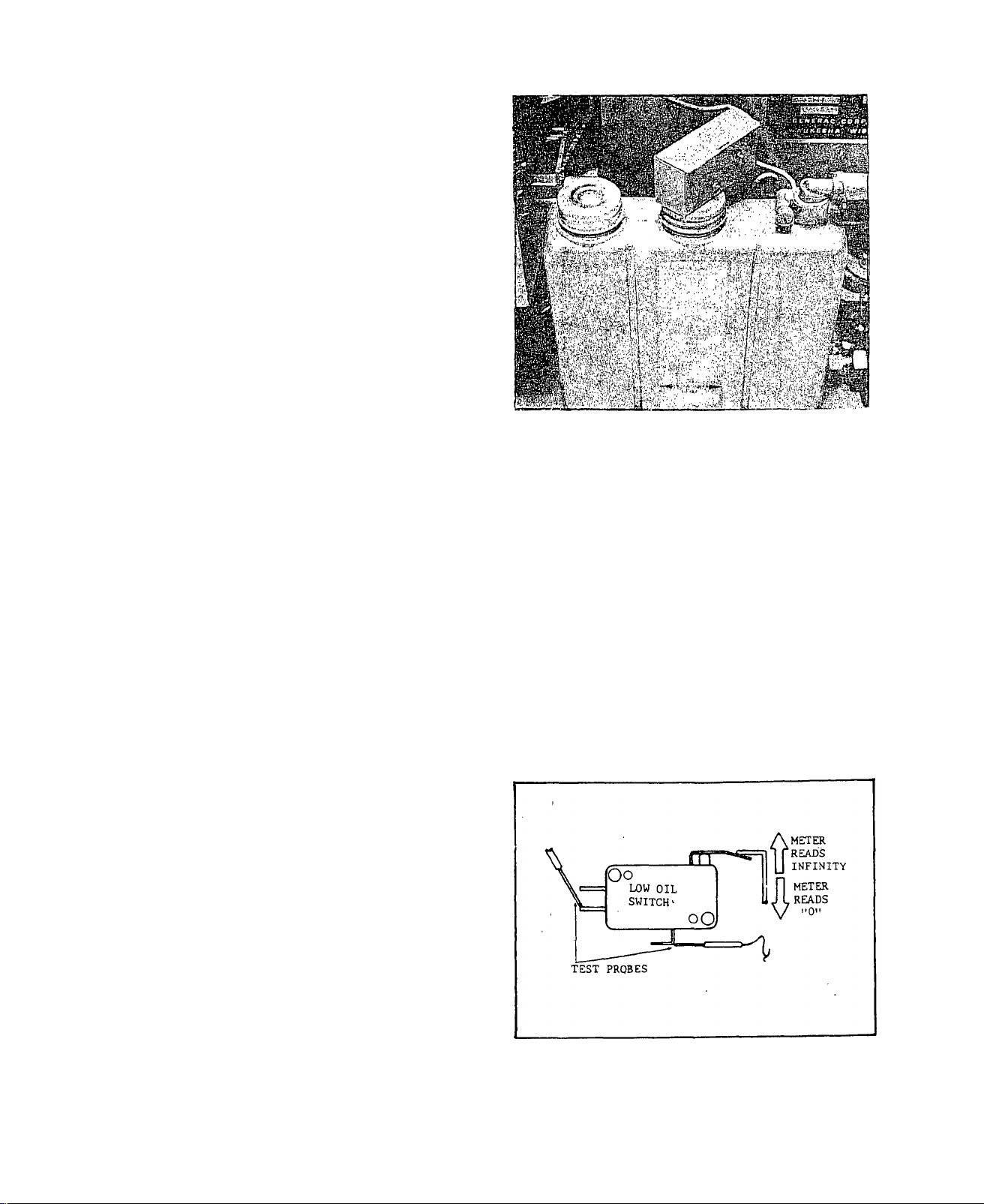
TEST 10 - LOW OIL SWITCH
A.) Remove one screw that retains the Low Oil Switch Cover. Move Cover
out of the way.
Set VOM to "+DC" and to "Rxl" scale. Connect meter test probes and zero
the meter. Connect one meter test probe to lower left switch terminal
and remaining probe to ground terminal (bottom of switch). With switch
actuating lever DOWN (low oil condition), meter needle should swing up
scale to "Zero". If meter
A.) Remove one screw that retains the Low Oil Switch Cover. Move Cover
out of the way to.expose switch terminals.
Set VOM to "+DC" and to "Rxl"
scale. Connect meter test probes
and "zero" thé meter. Connect
one test probe to lower left
switch terminal. Connect remain
ing test probe to ground. With
switch actuating lever DOWN (low
oil level), meter needle should
swing upscale to "zero". With
switch actuating lever UP (norm
al oil level), meter needle should
drop all the way downscale to
"infinity". MAKE SURE GROUND WIRE
BETWEEN SWITCH BOTTOM TERMINAL AND OIL FILLER. NECK BRACKET SCREW IS
TIGHT.
.Refill tank
.Continue tests in "Diagnostic
Flow Charts", Section 3
4.» 6
Issued 3-78
Page 28
CAUTION
Before installing Low Oil Switch Cover, make sure the float arm is
riding on top of the switch actuating lever. If float arm has dropped
off of switch actuating lever, engine will not shut down when oil
level in tank is low.
RESULTS:.!.) Switch tests Bad
2.) Switch tests.Good...............Continue tests in "Diag
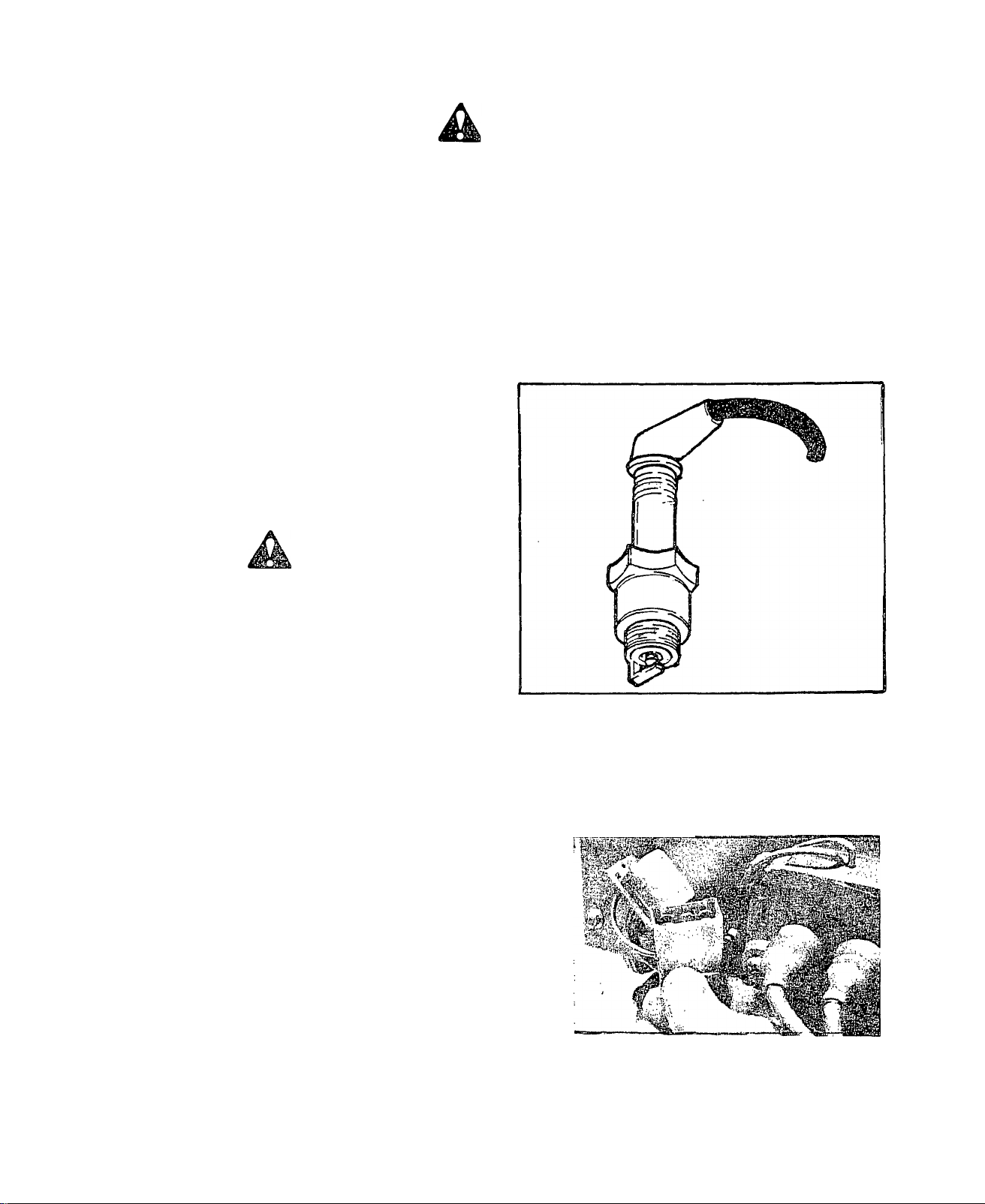
TEST 11 -SPARK PLUG
A,) Remove one spark plug. Connect
spark plug wire to plug. Ground
spark plug against engine. Hold
Start/Stop Switch at START and ob
serve spark plug. A sharp, snappy
spark should be seen. Repeat test
for second spark plug.
CAUTION
NEVER crank engine with a spark
plug or spark plug wire removed,
unless the spark plug or wire is
connected to a clean ground.
Failure to ground the plug or
lead can damage the Ignition coil,
............................................................
Replace Switch
nostic Flow Charts", Sec
tion 3
RESULTS: 1.) Sharp, snappy spark is
NOT observed.
2.) Sharp, snappy spark IS
observed,.
Test 12 - IGNITION MODULE “
A.) Unplug the Ignition Module
from its receptacle. Inspect the
connector pins in the module and
module receptacle - make sure
the pins are not bent or pushed
in. Install a new (or "shop") ig
nition module and check for norm
al spark.
RESULTS: 1.) Normal "hot" sparking...................................................Install a new Ignition
2.) Normal sparking NOT observed.... Continue tests in"Diagnos-
.........
....
........................................
......
.................................................................. .Continue tests in
.Replace spark plug
"Diagnostic* Flow
Charts", Section 3
Module, continue tests
tic Flow Charts", Section 3
Issued 3-78
Page 29

TEST 13 - IGNITION STATOR
A.) Remove the wire nut from Wire
No. 20.at the Low Oil Switch. Dis
connect the wire, to prevent inter
action. Then proceed a.s. follows:
^
a. Set VOM to ”Rxl00" and to ”+DC”.
Zero the meter. Connect one meter
^ A test probe to Pin No. 2 of the Ig-
cJwoj/nition Module receptacle. Connect
the second test probe to ground.
^v> Meter needle, should swing upscale
R^-^j^nd read appro.ximately 225 Ohms
(+10'^°)* This is the Ignition State
Charge Coil resistance.
RESULTS: 1.) Tests Bad
.......................................
2.) Tests Good
Reconnect Wire No. 20 at the
fore proceeding to next test
TEST 14 - IGNITION COIL
Set
A.)
MT
n
’+DC", then zero the meter. Conn
to "Rxl" scale and to
VOM
ect one meter test probe to Pin 4
of the Ignition Module receptacle.
Connect the remaining test probe
to Ignition Module receptacle Pin
1. Meter needle should swing up
scale and indicate the Ignition
Coil primary winding resistance
(about 0.5 Ohms).
.......................
b. S'et the VOM to ”+DC" and to ’’Rxl”
scale. Again zero the meter. Connect
one meter test probe to Ignition
Module receptacle Pin No. 3, and the
second probe to ground. Meter needle
should swing upscale and,read approx
imately 6 Ohms. This is the Ignition
Stator Trigger Coil resistance.
.
...........
,Install new Ignition Stator
.Continue tests in "Diagnostic
Flow Chart", section 3
Low Oil Switch and retain with wire nut be-
, Also install Ignition Module,.
4.8
Issued 3-78
Page 30

RESULTS: 1.) Checks BAD................................................Replace Ignition Coil
2.) Checks Good...........................................Continue with Paragraph "B"
B.) Set VOM to "RxlOO" scale and zero
the meter. Unplug both spark plug
wires from Ignition Coil, and in
sert the two meter test probes as
shown. Meter needle should indicate
secondary winding resistance, about
6500 ohms.
RESULTS: 1.) Checks Bad.............Replace. Ignition Coil
2.) Checks Good...
................................
Continue with Paragraph "C"
C.) Set VOM to ”Rxl0,000" scale and zero the meter. Connect one
meter test probe to Ignition Coil as in Paragraph ”B”, but conn
ect the second probe to ground. Meter needle shonld not swing
upscale (infinity).
RESULTS: 1.) Meter swings upscale.... Replace Ignition Coil
TEST
2.) Meter does not move
15 -LOW FUEL LEVEL
...........................
A.) Check fuel level in gas. tank.
The vehicle engine fuel pickup
tube in the tank, is usually sev
eral inches longer than the alter
nator pickup tube. This means that,
even if adequate fuel is available
for vehicle engine operation, the
fuel may be below the alternator fuel
pickup tube.
Continue with tests in
"Diagnostic Flow Charts",
Section 3
To Vehicle
Engine
Fuel
Tankik p
\1
Installation Of Second
Fuel Pick Up Tube In
Tank Outlet.
To Alternator
Engine
Pipe
Nipple
Variable
Potentiometer ^
_L
\ Anti-Siphon
■^Holes
1'
3 in.
♦
Pipe Cap
To Alternator
Engine
3 In
Fuel Pickup/Float
B.
Assembly
To Vehicle
Engine
Fuel Gauge
Connection
Fuel
Quantity
Float
Issued 3-78
4.9
Page 31

TEST 16 -NO FUEL FLOW
At carburetor inlet, spread clamp
and slide it down the fuel inlet
hose. Disconnect the hose from in
let fitting - BE CAREFUL NOT TO
BREAK THE FITTING. Hold open end
of fuel hose over a suitable con
tainer. Hold Start/Stop Switch,at
START to crank engine. Check for
fuel flow from fuel inlet hose.
DANGER
A’
Gasoline vapors are highly flammable and. explosive. Do not Jbermit
smoking, open flame or sparks in the vicinity while checking for
fuel flow.
RESULTS: 1.) Fuel.. Flow Bad.............................................
2.) Fuel Flow Good
TEST 17-4 AMP FUSE
A.) Remove 15 Amp fuse to disconn
ect starting, circuit. Remove the
2 screws that retain the top panel.
Remove the top panel.
........................................
B.) Remove the 4 Amp Fuse from the
Printed Circuit Board. Check visu
ally for an open fuse element. Set
VOM to "+DC" and to "Rxl" scale.
Zero the meter. Connect meter test
probes to both ends of fuse. Meter
needle should swing upscale and in
dicate "zero".
Continue tests in "Diagnostic
Flow Charts", Section 3
Continue tests in "Diagnostic
Flow Charts", Section 3
RESULTS: 1.) Fuse checks Good
2.) Fuse checks Bad..................................Replace Fuse
4.10
...................................
Continue tests in
Diagnostic Flow Charts"
Section 3
Issued 3-78
Page 32

TEST 18 - PRINTED CIRCUIT BOARD
A.) Depress locking tangs of Print
ed Circuit Board connector plug and
disconnect plug from its receptacle.
On the connector plug, locate Pin #
4 to which Wire #20 attaches. Set
the VOM switches to ’.’AC" and to 2,5
Volts, Connect one VOM test probe to
Connector plug Pin #4 and the other
test probe to ground. Crank the eng
ine - Tneter needle should swing up
scale and indicate approximately 0,5
volts AC (pulsing voltage),
RESULTS: 1,) Meter indicates 0,5 Volts
2,) Meter does not indicate,,
0,5 volts
B.) Plug printed circuit board
connector plug in. Locate Wire
#14 connection at terminal strip.
Set VOM to "+DC" and to ''50V'
scale. Connect POSITIVE (+) meter
test probe to terminal strip wire
#14 connection and other test
probe to ground. Crank the engine.
Meter should indicate battery vol
tage (9-12 volts DC),
RESULTS: 1,) Meter indicated 12 volts,
2,) Meter did NOT indicate,,.
12 volts
TEST 19 - FUEL FILTER
,Go to Paragraph ”B”
.Check Wire #20 between Print
ed Circuit Board and Terminal
Strip, and between Terminal
Strip and Ignition Module for
open or shorted condition.
• Continue tests in ’’Diagnostic
Flow Charts”, Section 3
Check Wire. #14 between Terminal
Strip and Printed Circuit Board
for open or shorted condition.
If not open or shorted, replace
Printed Circuit Board,
#
Remove and replace the In-Line
Fuel Filter, Make sure arrow on
Fuel Filter points towards the
solenoid-operated Fuel Shutoff
Valve, Repeat TEST 16 on Page
4.10 (No Fuel Flow).
Issued 3-78
Page 33

RESULTS: 1.) Fuel Flow Good,
engine still won't start
2. ) Fuel Flow Bad
........................................................
............................................
3. ) Fuel Flow Good and engine
starts..........................Repair completed,
TEST 20 - FUEL SHUTOFF SOLENOID
A.) Disconnect Fuel Shutoff Solenoid
Wire #14 at the Fuel Pump terminal.
Crank the engine for 2 or 3 seconds,
then touch the terminal end of Wire
#14 to the Fuel Pump terminal. Fuel
Shutoff Solenoid should actuate and
sound of Fuel Pump should change not
iceably.
RESULTS; 1.) Fuel Shutoff Solenoid did
not actuate
............................................
2.) Fuel Shutoff Solenoid
actuated
................................................
Go to TEST 23
Go to TEST 20
dis-
continue tests
•Replace Fuel Shutoff Solenoid
.Continue tests in "Diagnostic
Flow Charts", Section 3
TEST 21 - FUEL PUMP
A.) Disconnect BOTH Wires #14 at the
Fuel Pump terminal. Set VOM to "+DC"
and to "Rxl" scale. Zero the meter.
Connect one meter test probe to the
Fuel Pump connection terminal and the
remaining test probe to ground. Meter
needle should swing upscale and read
approximately 50 Ohms.
RESULTS: 1») Pump tests Good
................................................
Go to-Paragraph "B"
2.) Pump tests Bad^..............................................Replace Fuel Pump
B.) Reconnect both Wires #14 to Fuel Pump connection terminal,
engine and listen for sound of fuel pump.
RESULTS: 1.) Pump does not pulse.......................................Go to Paragraph "C"
2.) Pump pulses normally
............................
..Continue tests in "Diagnostic
Flow Charts", Section 3
Crank the
4.12
Issued 3-78
Page 34

•C.) Disconnect Wire #14 at Fuel Pump
terminal. Set VOM to ”+DC” and to 50
Volt scale. Connect the POSITIVE (+)
meter test probe to the terminal end
of Wire #14. Connect the COMMON test
probe to ground. Crank the engine -
meter needle should deflect upscale
and indicate battery voltage (about
12 volts DC).
RESULTS: 1.) Meter does NOT read 12 volts............................................*...Go to Paragraph ”D’
2.) Meter indicates 12 volts, but pump
does not pulse when Wire #14 is
connected to its terminal.'......................................................Replace Fuel Pump
D,) Check Wire #14, between the Fuel
Pump and terminal strip in control
panel, for open or shorted condition.
RESULTS: 1.) Wire #14 checks Good
2.) Wire #14 checks Bad..................................................Repair/Replace Wire #14
TEST 22 -CHECK INSTALLATION
Does the installation include a second in-line fuel filter? If so,, check
the filter for clogging. If a shutoff valve is installed in the fuel
supply line, make sure the valve is open. Finally, make sure the air in
let opening in the door is large enough. An insufficient supply of cool
ing air will result in high compartment temperatures and possible fuel
line vapor lock. Refer to INSTALLATION MANUAL, RECREATIONAL VEHICLE ALT
ERNATORS (Part No. 49204).
...................................................
Continue tests in”Diagnos-
Issued 3-78
tic Flow Charts", Section 3
4.13
Page 35

TEST 23 - CARBURETOR
Ad just Jets: Turn Needle Valve
clockwise until it just closes DO NOT TURN IN TOO FAR, OR JET
MAY BE DAMAGED. Then open needle
valve l\ turns (counterclockwise).
Close Idle Valve in same manner,
then open 1^ turns. This initial
adjustment will permit the engine
to be started and warmed up.
With engine running, hold the throttle lever against the Idle Stop. Set
the Idle Speed Adjusting Screw to obtain 1400 rpm. Turn Idle Valve SLOW
LY clockwise to obtain 1400 rpm, 93 volts AC, or 46 Hz. Then turn Idle
Valve SLOWLY clockwise (lean mixture) until engine misses or engine
speed slows. Finally, turn Idle Valve one-half turn counterclockwise.
Hold throttle lever against idle
stop and turn Idle Speed Adjust
ing Screw to obtain 900 rpm (30
Hertz or 60 Volts a-c). Then bend
Governed Idle Tab (see illustrat
ion at right) to obtain 1400 rpm
(93 Volts a-c or 46 Hertz).
___________________
NOTE
Governed idle must be adjusted
for proper operation. The smaller
spring keeps the engine on govern
nor, even at idle speed. Idle
speed should not be lower then
1100 rpm, 73 volts or 37 Hz.
Release throttle lever and let'engine accelerate to governed speed.
Apply a load to the alternator, between'3000 and 4500 watts. Turn
Needle valve SLOWLY clockwise (lean mixture) until voltage reading
starts to drop off. Then turn Needle Valve counterclockwise until
the highest voltage reading is obtained. When the highest voltage
is obtained, turn the Needle Valve counterclockwise an additional
1/8 of a turn.
Check Float Valve and Seat; Refer to engine section of this Manual
for procedures. Inspect float valve and its seat for damage, dirt
or wear.
Check Float Level; Refer to engine section of this Manual for pro
cedures .
4.14
Issued, 3-78
Page 36

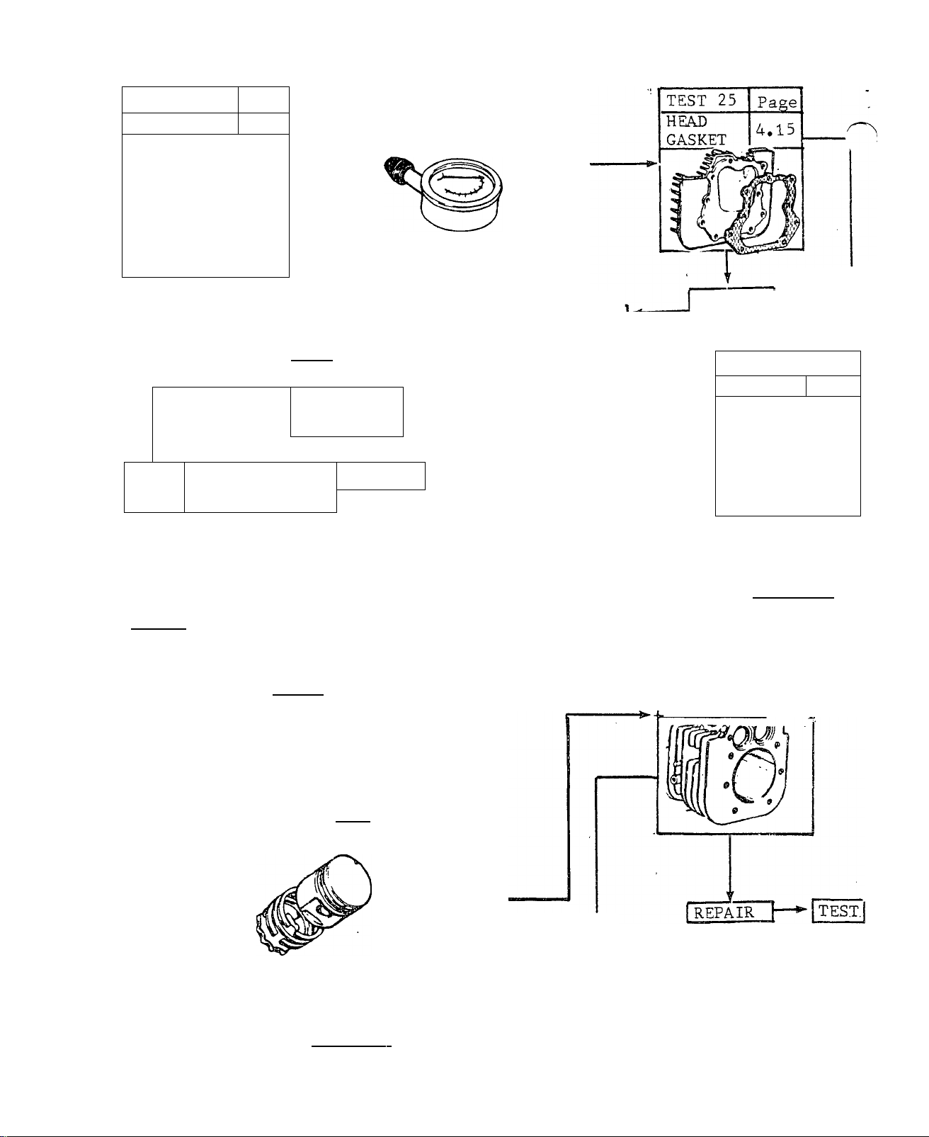
TEST 24 - COMPRESSION
A. ) Use a standard compression gauge.
Insert end of gauge into spark plug
hole. Open throttle wide open and
crank the engine. Repeat compression
check for second cylinder. There
should be no more than a 25 per cent
difference in compression between
the two cylinders. A greater pressure
difference indicates loss of compress
ion.
COMPRESSION
GAUGE
SPARK PLUG
REMOVED
RESULTS: 1.) Compression Low
...........................
Paragraph ’’B”
2.) Compression Good....Go to
Test 29
B. ) Squirt a few drops of oil into the
spark plug opening of one cylinder.
Repeat compression Test of Paragraph
’’A” above. If compression is higher
than was obtained in "A”, RING or CYL
INDER wear is indicated. If little or
no difference in compression is noted,
compression loss is due to a leaking
HEAD GASKET, FAULTY VALVES, etc.
Repeat Paragraph "B" for second cylinder,
RESULTS: 1.) Compression Increased,.Go
to Test 27 and 28
2.) No increase
........................................
to Tests 25 and 26
TEST 25 HEAD GASKET
Go to
Go
#
Refer to ENGINE REPAIR section of this Manual.
TEST 26 VALVES
Refer to ENGINE REPAIR section of this Manual.
TEST 27 RINGS
Refer to ENGINE REPAIR section of this Manual.
TEST 28 CYLINDER
Refer to ENGINE REPAIR section of this Manual.
Issued 3-78
4.15
Page 37

TEST 30 CHOKE
A.) Hold the Start/Stop Switch at
START position and crank engine.
While the engine is cranking, the
Choke Solenoid should pulse., the
choke from a ”No-Choke” to a
’’Choke’’ position, at a rate dep
endent on ambient temperature.
RESULTS: 1.) Choke Movement Good
2.) Choke does not move
B.) Inspect the Choke Assembly and Linkage for binding caused by im
proper choke support alignment, dirt, etcJ Push the Choke back and
forth with your finger - no mechanical binding or sticking should be
observed.
RESULTS; 1.) Choke is Binding.........................................Adjust or clean choke linkage
Choke moves freely
C.) Loosen the two solenoid adjusting screws. Adjust solenoid axial
movement so that, with the carburetor choke valve closed, the choke
solenoid plunger is bottomed. Tighten the two adjusting screws, and
check again for correct choke action.
RESULTS; 1.) Solenoid pulls in normally
2.) Solenoid does not operate normally...Go to Paragraph ”D”
D.) A small 2-wire disconnect is located adjacent to the Choke assembly.
Wire #90, from the Printed Circuit Board to the Choke Solenoid, and
Wire #14, from the Printed Circuit Board to the Choke Bi-Metal, can be
disconnected here. The following test is a check of the Printed Circuit
Board, which governs Choke pulsing action.,
............................................
...........................................
............................
...................................................
Go to Paragraph ”C” •
Go to Test 31
Go to Paragraph ”B”
Go to Test 31
CAUTION
The VOM positive (+) test probe MUST be connected to the Wire #90
pin on the FEMALE half of the disconnect. This is wire #90 from the
Printed Circuit Board. DO NOT connect the test probe to the male
half of the disconnect (wire. #90 from the Choke Solenoid). Wire #
90, from the Choke Solenoid to the male half of the disconnect, is
HOT while the engine is being cranked. Connection of the VOM to the
Wire #90 MALE disconnect pin will seriously damage the meter as
soon as the engine is cranked.
4.16
Issued 6-78
Page 38

Unplug the mating halves of the
small disconnect. Locate the male
and female pins that connect Wire
#90 from the Choke SOLENOID (NOT
from the Choke Bi-Metal). Set the
VOM to ”+.DC” and to ”Rxl” scale,
then zero the meter. Connect the
POSITIVE (+) meter test probe to
the FEMALE Wire #90 pin, NOT TO
THE MALE WIRE #90 PIN. Connect the
common (-) test probe to ground.
Crank the engine. Meter needle
should swing upscale, then drop
downscale in a pulsing cycle.
RESULTS: 1.) Meter needle does NOT move
2.) Check is Good, but on sub
sequent tests Choke does not
operate normally
TEST 31 PRE-CHOKE
A.) With the Choke Bi-Metal cold
(ambient temperature)., the carbu
retor Choke Valve should be app
roximately 1/8 inch away from its
vertical position, and towards a
CHOKE position. If necessary,
loosen the Bi-Metal, adjusting
screws and move the Bi-Metal to
obtain this setting. This is the
"Pre-Choke” position.
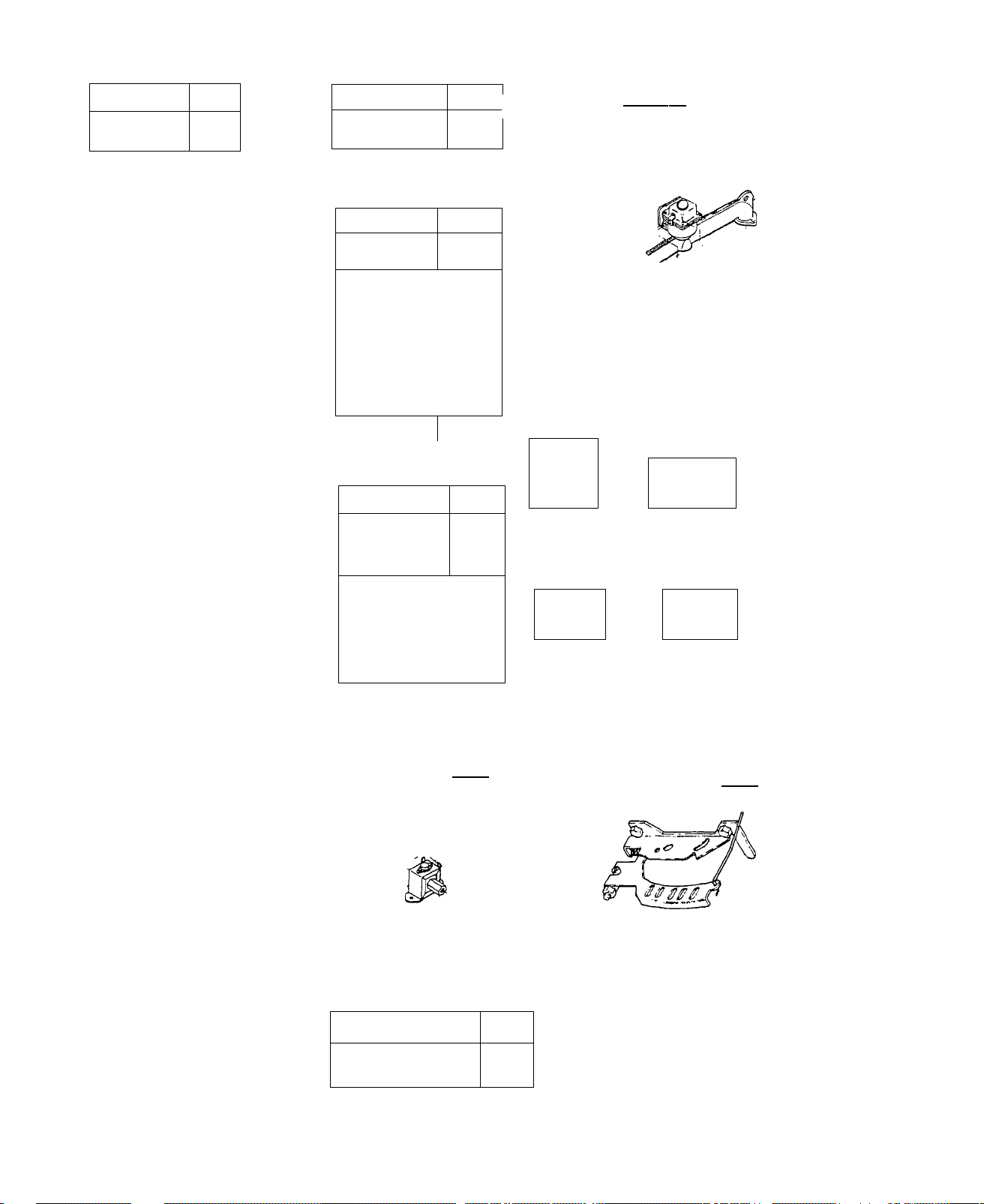
TEST 32 GOVERNOR
..................................
................
..Replace Printed Circuit Board
Replace Choke Assembly
A.) Adjust Carburetor jets and Governed Idle as outlined in Test 23,
CARBURETOR. These adjustments must be completed before attempting to
adjust the Governor.
RESULTS: 1.) Problem, is corrected.....................................................................Test Completed
2.) Engine "hunts" ,and/or AC Voltage
or Frequency is incorrect...........................................Go to Paragraph "B"
Issued 6-78
4.17
Page 39

B.) Loosen Governor Lever Nut,
Push Governor Lever all the way
counterclockwise to open thrott
le wide open. Hold the Governor
Lever in this position, then ro
tate the Governor shaft all the
way counterclockwise, as far as
it will go. Tighten the Governor
Lever Nut to 100 inch-pounds.
RESULTS: 1.) Engine runs normal, provides
62 Hz at "No-Load"..............................................................Test Completed
2.) Engine "hunts" and/or AC Voltage
or Frequency is incorrect......................................................Go to Paragraph "C"
C.) With engine running, turn
Governor Adjusting Nut to ob
tain 62 Hz at "No-Load".
Governor tab should be bent to
apply slight tension to governed
idle spring at 1860 rpm (62 Hz
or 124 volts), with no electrical
loads applied. Spring should be
loose when loads are applied.
Governed
IdleTang
Governor
Shaft
Governor
Lever Nut Governor
Lever
;
Idle Speed
Adjustment Screw
Carburetor Body
Throttle Lever/
Governor Adjustincj Nut
NOTE
The Governed Idle spring, prevents engine speed surging and "hunting"
during "No-Load" conditions. When an electrical load is applied, the
spring will normally become loose and ineffective.
TEST 33 FREQUENCY
A.) Use an accurate Frequency Meter to check alternator output frequen
cy. The Model 5515 Load Bank is equipped with a frequency meter, as well
as provisions for reading voltage and amperage. Frequency should be 63
Hz (63 cps) at "no-load". With an electrical, load applied, frequency
should be 59-63 Hz and stable. (All mechanical governors have a normal
ffspeed" fluctuation, which is the reaction time of the governor.)
'o
RESULTS: 1.) Frequency checks Bad
......................................
Continue tests in "Diagnostic
Flow Charts", Section 3
2.) Fi'equency Checks Good
...............................
Continue tests in "Diagnostic
Flow Charts", Section 3
4.18
Issued 6-78
Page 40

TEST 34 - EXCITATION WINDINGS
A. .) Remove Control Panel top cover.
Locate the white connector plug at
the rear of the panel. Unplug the
connector from its receptacle. Set
VOM to '’+DC” and to ”Rxl" scale,
then zero the meter. Connect one
meter test probe to receptacle pin
#2. Connect the second test probe
to receptacle pin #6. Meter needle
should swing upscale and indicate
about 1.8 to 2.5.ohms. This is the
resistance of the stator excitation
winding..
RESULTS: 1.), Windings check Bad.
2.) Windings check Good
....................................................................
.............................
.....................................Continue tests in
''Diagnostic Flow Charts", Section 3
B. ) Set the. meter swLtches ..to "+DC!' and to "Rxl0,000" scale. Zero the
meter. Connect one teat, probe to white receptacle pin #2, and the other
test probe to ground. Meter needle should not move.
RESULTS: 1.) Meter needle swings upscale
2.) Meter needle does not move
..............................................
..................................................
...Replace stator
"Diagnostic Flow Charts", Section 3
TEST 35 - CARBON BUILDUP
A.) Excessive carbo.n buildup in the engine combustion chamber can ser
iously affect engine power. Carbon deposits should be removed every
500 hours of operation, or whenever the cylinder heads are removed. If
engines are run at a steady load, it may be necessary to remove carbon
more often. Refer to ENGINE REPAIR section of this Manual for cylinder
head removal and installation procedures. When reinstalling cylinder
heads, bolts must be installed in the proper location on the head and
the cylinder head must.be properly torqued.
Replace Stator
Continue tests in
TEST 36 - OUTPUT VOLTAGE
A,.) Use an accurate voltmeter or
the Model 5515 Load Bank to check
output voltage. When using a volt
meter, connect one meter test
probe to alternator output lead T1
and the remaining test probe to 2
output leads T2. Voltage should he.
approximatel.y 125 volts at "no-load",
and.115 - 125 volts AC under load.If
voltage checks good, check frequency.
Issued 6-78
4.19
Page 41

TEST 37 - SENSING TRANSFORMER
Either of 2 Sensing Transformers may be used. I4ien checking Transform
er windings for an open condition, resistance readings obtained should
be as shown in the following CHART:
TRANSFORMER
MAKE
WesCoil
CoilTran
RESIS.TANCE [in OHMS)
Primary Secondary
745-825
824-1114
1603 - 2169
1222 - 1654
A.) Remove wire nuts that retain
wires #11 and #22, between the
Transformer and Voltage Regulator
Disconnect the wires. Set VOM to
”+DC’ and to ’’RxlOO” scale. Zero
the meter. Connect one meter test
probe to Wire #11, and the second
test probe to Wire #22. Meter
needle should swing upscale and
indicate resistance for SECONDARY
Sensing
Transformer
With Wires To
Secondary
Winding
winding.
RESULTS: 1.) Checks Good.
Continue tes.ts in "Diagnos
tic Flow Charts", Section 3
2,) Checks Bad..
.Replace Sensing Transformer
B. ) Set VOM to "+DC" and to "Rxl0,000" scale. Zero the meter. Connect
one meter test probe to Wire #11. Connect the second test probe to
Ground. Meter needle should NOT move. Any needle movement indicates a
shorted condition.
White ' Pin No. 5
Receptacle
Pins No. 3 and
No. 5 to Primary
Winding of
Transformer
---------------
RESULTS: 1.) Tests Good....
...............................................................
Continue tests in "Diag
nostic Flow Charts"
2.) Tests Bad...................................................................Replace Transformer
C. ) Unplug the white connector plug from its receptacle. Set the VOM
to "+DC" and to "RxlOO" scale. Zero the meter. Connect one meter test
probe to White receptacle Pin #3. Connect the second test probe to
white receptacle Pin #5. Meter needle should swing upscale and indic
ate resistance shown in CHART for PRIMARY winding,
RESULTS: 1.) Tests Good......................................................Continue tests in "Diagnostic
Flow Charts", Section 3
2.) Tests Bad
...................................................
Replace Transformer
D. ) Set VOM to "+DC" and to "Rxl0,000" scade. Zero the meter. Connect
one meter test probe to white receptacle Pin #3. Connect the remain
ing test probe to Ground. .Meter.needle should not move.Any movement
of the needle indicates a shorted condition.
RESULTS. 1.) Tests Good......................................................Continue tests in "Diagnostic
Flow Charts", Section 3
2.) Tests Bad
....................................................
Replace Transformer
4o20 Issued 6-78
Page 42

TEST 38 - MAIN CIRCUIT BREAKER
NOTE
If the alternator has. been re.eonnected to provide a dual voltage
of 120 and 240 volts, the Main Circuit Breaker will be disconnec
ted from the circuit. See WIRING DIAGRAMS, Section 2.
A.) Disconnect wires from Main
Circuit Breaker terminals ”A" and
”B", to prevent interaction. Set
VOM to "-)-DC" and to "Rxl" scale.
Zero the meter. Connect one meter
test probe to Terminal ”A" and
one probe to Terminal . ”B’.', With
the Circuit Breaker ON, meter
needle should swing upscale and
indicate ZERO ohms. With Breaker
OFF, meter needle, should drop all
the way downscale to !.'Infinity”,
TEST 39 - ROTOR
A.) Use a ^ inch nut driver to re
move the No. 8-32 screw that reta
ins the Brush Inspection Cover to
the Rear Bearing Carrier. Remove
the Brush Inspection Cover, Set a
VOM to "Rxl" scale and to "+DC".
Zero the meter. Connect one meter
test probe to the brush terminal
furthest from the Brush Inspection
Cover opening. Connect the . s.e-cond
test probe to Ground, Meter needle
should swing upscale and indicate
approximately 13 Ohms. (+10 %). •
■ RESULTS: 1.) Tests Good...,,
2.) Tests Bad,
B.) Use a \ inch nut. driver to re
move the Brush terminal screws, as
well as the Brush Holder reta.Lning
screws. With VOM set to. "+DG" and
to "Rxl" scale, repeat the test of
Paragraph "A" directl.y on the Rotor
Slip Rings, Meter needle should, swing
upscale and indicate, approximately 13
Ohms (+ 10%).
..............................
.Continue tests in "Diagnostic
Flow Charts", Section 3
.Go to Paragraph "B"
Issued 6-78
4.21
Page 43

RESULTS: 1.) Tests Good
..............................................
Go to Paragraph ’’C”
2.) Tests Bad.............................................Replace Rotor
C.) Inspect Brushes and Slip Rings. Replace Brushes if cracked, broken
or less than 5-/16 inch long. If Slip Rings aire dirty or tarnished,
clean with fine sandpaper. DO NOT USE EMERY CLOTH.Then repeat Test "A”.
RESULTS: 1.) Tests Good............................................Continue Tests in "Diagnostic Flow
Chart", Section 3
2.) Tests Bad
..........................................
Replace Rotor Assembly
TEST 40 - FIELD BOOST
A,) Unplug the Ignition Module
from its receptacle to prevent the
engine from starting. At the rear
Pin No. 4
of the control panel (on the panel
floor), disconnect the white conn
ector plug from its receptacle.
Set the VOM to "+DC" and to a scale
that will permit 12 volts to be
read. Connect the Positive (+) test
probe to white receptacle Pin #4
and the COMMON test probe to Ground.
Crank the engine. Meter should indi
White
Receptacle
Field Boost:
From PCB Pin No. 2, to
White Receptacle Pin No. 4,
to Brushes & Slip Rings,
To Rotor Windings.
cate about 9-12 volts DC. Reconn
ect the white connector plug before
proceeding.
RESULTS: 1.) Checks Good
...............................
Continue|with "Diagnostic Flow
Charts", Section 3
2.) Checks Bad
.............................
Go to Paragraph "B"
B.) Unplug the connector plug from the Printed Circuit Board and from
the white.receptacle. Set VOM to "+DC" and to "Rxl" scale. Zero the
meter. Connect one meter test probe to printed circuit board connect
or plug (Pin #2). Connect the second test probe to white receptacle
connector plug (Pin #4). Meter needle should swing all the way upscale
to "zero
RESULTS; 1.) Wire #4 checks good..............................................Replace Printed Circuit
Board
2.) Wire #4 checks Bad............Repair/replace Wire #4
RESULTS: 1.) Checks Good, but checked Bad
in Paragraph "A"
..........................................
Check Wire #4, between the
.Printed Circuit Board and
white receptacle
2.) Checks Bad.
.Replace Printed Circuit
Board
4.22 Issued 6-78
Page 44

TEST 41 - STATOR
A.) Disconnect Wires #11 and #33
from the Main Circuit Breaker, Dis
connect two Wires #T2 from customer
wiring. The two wires #T2 are also
labelled.#22 and #44. Set VOM to
''+DC” and to "Rxl" scale. Zero the
meter. Connect meter test probes to
Wires #11 and #22, and. observe the
reading. Then connect test probes
to Wires #33 and #44 and observe
the reading. In each case, the meter
needle should swing upscale, to app
roximately 0,42'Ohms.
RESULTS: 1.) Tests indicate open.
2.) Tests Good.
B.) Set VOM to ”+DC” and to ”Rxl0,000!’ scale. Zero the meter. Connect
one meter test probe to Wire. #11..Connect the second test probe to
Ground. Observe meter. Then connect one test probe to Wire #33 and the
other test probe to Ground, In each case, the meter needle, must not
move (Infinity). Any movement of the meter needle indicates a "shorted”
condition.
RESULTS : 1.) Tests indicate "sho.rt"..............................
2.) Tests Good
................................................
............
.Disassemble, alternator. Test
stator with VOM and with an
Insulation Breakdown Tester.
Replace, if defective.
,Go to Paragraph "B"
Di.sas,semble. alternator. Test
stator with VOM and with an
Insulation Breakdown Tester,
Replace if defective,
...Continue tests in "Diagnost
ic Flow Charts", Section 3
Battery Charge Tests
TEST 42 - CHARGING OUTPUT
A.) Disconnect Wire #66 at the
control panel Terminal Strip. Then
connect an Ammeter in series with
the disconnected Wire #66 and the
Terminal Strip connection. Start
the alternator. The Ammeter, should
indicate an output, dependent upon
battery condition.
Issued 6-78
Page 45

RESULTS: 1.) Ammeter indicates discharge or
no output............................................................................
2.) Ammeter indicates a charge
..................................................
Go to Test 43
Discontinue tests
Disconnect Ammeter from circuit and reconnect Wire #66 to Terminal
Strip before proceeding.
TEST 43 - CIRCUIT BREAKER
A.) Disconnect Wires #77 and #78
from the Circuit Breaker. . Set VOM
to ”+DC” and to "Rxl*' scale, and
zero the meter. Connect meter
test probes to Circuit Breaker
terminal studs. Meter needle should
swing upscale to "zero".
RESULTS: 1.) Checks Good........................................................I....G0 to Test 44
2«) Checks Bad,
................................................................Replace Circuit Breaker
Battery Charge
Circuit Breaker
TEST 44 - DIODES D1 & D2
A.) Disconnect Wire #78 at the
battery charge circuit breaker.
Set VOM to "+DC" and to "Rxl"
scale, then zero the meter.
Connect the Positive (+) »test
probe to Wire #78 from Diode D2.
Connect the COMMON (-) test
probe to Ground. Meter, needle
should not move. Set meter to
"-DC" (or reverse the test prob
es). Meter needle should swing
(Looking Rearward From Front of Control Panel)
upscale to some raid-scale read
ing (approximately 7 - 1.2. Ohms).
RESULTS: 1.) Tests Good.
.Reconnect Wire #78. to. circuit
Breaker, go to Paragraph "B"
2,). Tests Bad,.
.Replace Diode D2
B.) Remove wire nut and disconnect Wire #55, near Diode. Dl. Set VOM
to "+DC" and to "Rxl" scale. Zero, the mater. 'Connect the. Positive ( + )
test probe to Wire #55 from Diode Dl. Connect the COMMON (-) test
probe to Ground. Meter needle should.not move. Set VOM to "-DC" (or
reverse the test probes). Meter needle should swing upscale, to some
mid-scale reading (approximately 7- 12 Ohms).
Control Panel Top
4.24
Issued 6-78
Page 46

RESULTS; 1.) Tests Good......................................Reconnect Wire #55, retain with
wire nut. Go to Test 45
2.) Tests Bad........................................
Replace Diode Dl
TEST 45 -STATOR BATTERY CHARGE WINDINGS
A.) Remove the 15 Amp Fuse. Discon
nect Wire #77 from Battery Charge
Circuit Breaker, Remove wire nut
from the Wire #55 connection, near
Diode Dl, then disconnect the wires.
Set VOM to ”+DC” and to "Rxl” scale.
Zero the meter. Connect one meter
test probe to Wire #55, Connect the
other test probe to Wire #77, Meter
Battery
Charge Circuj^
Breaker
needle should swing upscale and in
dicate approximately 0,20 Ohms.
Wire No. 78
RESULTS
1, ) Tests Good,
2. ) Tests Bad..
.Go to Paragraph ’’B”
.Replace Stator
B.) With 15 Amp Fuse still removed, set VOM to "+DC" and to *'RxlO,000"
scale. Zero the meter. Connect one meter test probe to Wire #55, and
the other test probe to Ground, Meter needle should not move (infinity),
RESULTS; 1,) Meter needle moved upscale
2,) Meter needle did not move,,,
..............................................
........................................
Wire No. 77
^ Nut
Wire
No 55
Shorted condition indi
cated, replace Stator
.Checks Good
Issued 6-78
4.25
Page 47

PART III
ALTERNATOR REPAIR
Section Title Page
5 CONTROL PANEL
Customer Wiring Connections................................................................................................5.1
Voltage Regulator................................................................................................................... 5.1
Printed Circuit Board............................................................................................................... 5.3
Diodes D1 and D2...................................................................................................................5.4
Other Components..................................................................................................................5.4
Panel removal......................................................................................................................... 5.4
6 ALTERNATOR
Rear Bearing Carrier...............................................................................................................6.1
Stator ......................................................................................................................................6.2
Rotor...................................................................................................................................... 6.3
Flexible Coupling.....................................................................................................................6.4
Fan ..........................................................................................................................................6.5
Engine Adapter/Ignition Stator.............................................................................................. 6.6
7 REASSEMBLY
Engine Adapter/Ignition Stator................................................................................................7.1
Fan .........................................................................................................................................7.1
Flex Coupling/Rotor................................................................................................................7.1
Stator ......................................................................................................................................7.2
Rear Bearing Carrier............................................................................................................... 7.2
Control Panel...........................................................................................................................7.3
Page 48

CONTROL PANEL
CUSTOMER WIRING CONNECTIONS
Customer wiring connections for
120 volts only are shown at right.
A 3-wire cable should be used.
Connect two alternator T2 wires to
one cable wire. Connect one alter
nator Tl'wire to a second cable
wire. The third cable wire should'
be connected to the grounding lug,
as shown at right.
NOTE
Panel output wiring can be reconn
ected to supply a dual voltage of
120/240 volts.. See Section 2. A 4-
wire cable is required.when supply
ing dual voltage.
__________
5
VOLTAGE REGULATOR
The Voltage Regulator used on the TXP provides a constant voltage to
frequency ratio of 2 to 1, That is, when alternator frequency is 60 Hz,
voltage output will be 120 volts a-c ( + 27o). If frequency should drop
to 55 Hz, output voltage would also drop, to about 110 volts a-c.
The Voltage Regulator Assembly for
the Model 6931-1 TXP is shown at
right. Be sure to check the wiring
diagram for the specific model in
volved. The following CHART lists
Regulator wires and their function.
------T3--------Connector
Wire #
1
2
4
6 #6 . .
11
22
Pin Function
#1
#2
#4
DC Current from (-) brush and slip ring
AC Current from excitation windings
DC Current to (+) brush and slip ring
AC.Current from excitation windings
,#3
#5
120 volt sensing from Sensing Transformer
120 volt sensing from sensing Transformer
Issued 3-78
5.1
Page 49

VOLTAGE REGULATOR ADJUSTMENT
The Voltage Regulator is adjusted at the factory and normally requires
no additional adjustment. If the engine is running at 62 Hz "No-Load"
and voltage readings are incorrect, the Regulator may be adjusted. An
accurate Frequency Meter and Voltmeter are required to adjust the Reg
ulator. The Model 5515 Load Bank.provides both these instruments. The
following procedure covers use of the Load Bank for Regulator adjust
ment.
1. Connect 3-wire cord set (Part
No. 27821) to alternator output
wires as shown above. Plug the
connector plug into the 120 volt,
3-prong connector plug on the
Load Bank. Set ALL Load Bank Hea
ter element switches to OFF. Set
Ammeter Hi-Lo Range Selector
Switch to 0-50 AMPS. MAKE SURE
THE LOAD BANK HEATER ELEMENT COV
ER IS OPEN.
2. Adjust carburetor jets and go
verned idle as outlined in Test
23, Page 4.14,
3. Adjust Governor as outlined in
Test 32, Page 4.18 and 4.19.
5.2
Issued 3-78
Page 50

PRINTED CfRCUIT BOARD
The Printed Circuit Board provides the. necessary components for;
1. Control of those functions■ required.for. engine starting, runn
ing, and stopping. These functions include:
a. Energizing the Fuel Shutoff Solenoid open and closed, as needed
b. Turning the electric fuel pump ON and OFF
c. Energizing the Choke Heater
d. Controlling Choke Solenoid action
2, Controlling current flow to the .Field .Boost circuit during a start.
This current is delivered..across the brushes and slip rings, to en
sure the presence of a magnetic field, around ..the Rotor during a start.
Thus, it is never necessary to energize the field,, since it is energ
ized during every start.
The illustration at right shows
the Printed Circuit Board comp
onents that can be tested, adj
usted, or replaced. Maintenance
is limited to (a) replacement of
the 4 Amp Fuse, (b) adjustment
of the Choke Adjustment potenti
ometer, or (c) replacement of
the entire Printed Circuit Board.
The Printed Circuit Board recept
acle and its mating connector are
shown at right. Notice the funct
ions of each pin in the connector
and receptacle.
Wire
Pin
No.
1
2
3
4 20
5
6
7
8
No.
15 12 VOC
4
90
.— —
14
10
91
Nominal
Value
6-12 VDC
0 OR 12 VDC
/Pi 11 Qinn)
\ r u 1 o H 1 u 1
0 • 3 VAC
12 VDC
•0-
0 OR 12 VDC
(Pulsing)
Function
Battery Voltage to PCB
Field Boost current to Rotor
Choke Solenoid
Ignition Stator output (Turns PCB
on during start)
Not Used
To Fuel Pump, Fuel Shutoff
Solenoid, and Choke Heater
PCB Ground
Choke Solenoid
The Choke Adjustment Potentiometer
can be used to increase.. o.r decrease
choke time. To INCREASE, choke time,
turn the adjustment screw clockwise.
To decrease choke time (or increase
"no-choke" time"), turn the slotted
adjustment counterclockwise.
n__n—TL-n__n
I .(i) (D © fp|
a 0
^£0
Or
0) 3
•pi:
UU
© <5) (fii ©
Receptacle
(viewed From Pin End)
Choke Time
Potentiometer
□ □ □ [Il
CE
□ □ □ □
Connector Plug
(Viewed From Wire End)
CAUTION
Be careful not to force the slotted
adjustment past its stops.
_______________________
Issued 3-78
5.3
Page 51

DIODES D1 & D2
Diodes Dl and D2 are a part of the
battery charging circuit. They fun
ction to convert the a-c output of
the battery Charge windings, to dir
ect current (d-c). Battery.charge ,
circuit checks are outlined in Tests
42 through 45, Pages 4.24 through
4,26, When replacing a defective di
ode, bleed off excessive .heat by
means of a heat sink - dfodes are ex
tremely sensitive to. heat.
OTHER COMPONENTS
other Control Panel components are
shown at right. These include (1)
a 40 Amp Main Circuit Breaker, (2)
a 15 Amp Fuse, (3) a Start/Stop
Switch, (4) battery Charge Circuit
Breaker, (5) Sensing Transformer,
and (6) Terminal Strip, Refer to
Sections 2 and 3 for troubleshoot
ing and testing of these, components,
Refer to the Wiring Diagram for *
each speci.fic alternator model when
reconnecting components.
PANEL REMOVAL
1, At front of alternator, locate
the large wire bundle from control
panel. Disconnect all wires from
this wire bundle, as follows:
(a) Wire #14 at fuel pump
(b) Wire #20 to Low Oil Switch
(c) Two Wires #15 at Starter Sol
enoid
(d) Wire #13 at Starter Solenoid
(e) Wire #17 at Starter Solenoid
(f) Wire #91 at Starter Solenoid
5,4
Issued 3-78
Page 52

2, At rear of Panel, (a.) disconn
ect spark plug wires from Ignition
Coil, (b) disconnect the wire con
nectors A and B,. and (c.) cut the
tie wrap that holds Wires #2 and
#6 to the stator bolt.
3, Remove the Panel top cover.
4. Remove wire nuts and disconnect
wires #11 and #22 to Sensing Tran
sformer, as well as Wire #55 to
Diode Dl. Disconnect wire #66 at
terminal strip. Disconnect wire #
77 at battery charge circuit brea
ker. Disconnect wires #11 and #33
from main circuit breaker and pull
through the snap bushing.' Remove
wire nuts from two. wires #T2 and
pull through snap bushing. Pull all
wires through snap bushing at
rear floor of panel.
Issued 3-78
5. At the rear exterior floor of
the control.panel, locate wires #
1, #2, #4 and #6 that connect into
the white receptacle. Use a small
screwdriver or pen knife to "un
lock” each female pin from its. re
ceptacle slot, while carefully pul
ling down on each wire. Remove all
four wires from the white receptac
le.
5.5
Page 53

6, Use a \ inch nut driver to rem
ove brush inspection cover screw.
Remove brush inspection cover. Use
a % inch nut driver to remove the
2 screws that retain the brush
holder. Cut the tie wrap that ret
ains the brush wires to the rear
bearing carrier.
7. Use a 7/16 inch socket to remove
the 4 bolts that retain the control
panel ho the stator can. Lift stra
ight up and remove the entire cont
rol panel.
5.6
Issued 3-78
Page 54

ALTERNATOR
rear bearing carrier
REMOVAL
1. Remove Control Panel as outlined in Section 5.
■Xtic.-;
i!.
- ■ 1
6
2. Remove the Fuel Shutoff Solenoid
Clamp screw. Tape o.r cover the open
end of the Fuel Filter to prevent
entry of dirt. Lay the Filter, Sol
enoid and hoses out of the way.
4. Use a 7/16 inch socket to remove
the 4 stator bolts. Use a wood or
fiber mallet to tap each projecting
corner of the Rear Bearing Carrier.
When Rear Bearing Carrier Is free
of the Rotor bearing, slide the wire
bundle through the snap bushing and
remove the Rear Bearing Carrier.
3. Use a k inch nut driver to remove
the 3 screws that retain the Fan
Guard. Remove the Fan Guard.
INSPECTION
1. Check closely for cracks, or other damage.
2. Check condition of snap bushing. Replace, if damaged.
3. Inspect threaded holes for condition of threads, damage, etc. Repair
or retap, as required.
Issued 3-78
6.1
Page 55

4. Inspect rotor bearing mating
surface on Rear Bearing. Carrier.
Replace Rear Bearing Carrier if
damaged, or worn exces.sively.
Use an inside micrometer to mea
sure bearing insert inside diam
eter. Inside diameter of insert
must be 1.3749 - 1.3755 inches.
]yia,ximum out-of-roundness must
not exceed 0.003 inch. Replace
Rear Bearing.-Carrier, if these
limits are exceeded.
STATOR
REMOVAL
1. Remove the stator-to-vibration
dampener bolts, hex nuts, and lockwashers, using a 9/16 inch socket.
Bolt heads are below the slide pan.
Rest the engine adapter housing on
a block of wood, then completely
remove all vibration dampener com
ponents.
2. Tap stator can free of engine
adapter. Carefully remove the stat
or can, along with the Alternator
Adapter Housing. If necessary to
remove the Alternator Adapter Hous
ing from the Stator can, place re
assembly alignment marks on Housing
and Stator can, then tap Housing
free of Stator can.
INSPECTION
1. Inspect Stator can. Alternator Adapter Housing, and Stator windings
for obvious damage. Replace, any component that appears to be damaged.
If required. Alternator Adapter Housing can be replaced. Replace the
entire stator can as an assembly.
2. Carefully inspect stator wiring for damage. Repair or replace de
fective wiring, as required.
2 Issued 3-78
Page 56

3. Set VOM to "+DC" and to "Rxl”
scale. Zero the meter. Connect the
meter test probes to stator wires
listed in CHART below. Meter needle
should sx^dng upscale and indicate
resistances as listed in CHART, If
meter needle does not swing upscale,
the winding being tested Ls ’’open”,
and stator should be replaced.
4. Use an INSULATION BREAKDOWN
tester to test stator windings for
defective insulation. Follow the
tester manufacturer’s instructions
carefully. Test each winding at
2000. volts, from the. winding to
ground, and at 1500 volts between
isolated windings.
NAME OF WINDING
Power
Power
Excitation
Battery Charge
ROTOR
1. Insert a screwdriver through
engine adapter housing cooling
air slots and between fan blades
to stop rotor from turning. Rem
ove 3 bolts that retain the flex- .
ible coupling to the fan. (LOC-TITE
was applied to threads of these
bokts during assembly.)Remove the
Rotor and Flexible Coupling.
WIRE,NO. READING
11 to 22
33 to 44
2 to 6’
55 to 77
"0742 '
0.42
2.30
0.20
REMOVAL
Issued 3-78
6. 3
Page 57

INSPECTION
1. Brush Holder & Brushes - The Brush Holder was removed along with
the Control Panel, and left attached to Control Panel wiring. Inspect
Brush Holder for obvious damage, cracks, etc. Replace, if damaged. In
spect brushes carefully. Replace if cracked, damaged or less than 5/16
inch long.
2* Rotor Bearing - Check bearing for freedom of rotation. Bearing must
spin freely on shaft. If bearing must, be replaced, use a bearing pull
er to remove, then press a new bearing over shaft.
3. Slip Rings - Inspect Slip Rings. If dirty, dull or tarnished, clean
until shiney with fine sandpaper..DO NOT USE EMERY CLOTH.
4. Rotor Windings ■ ? Inspect entire rotor for obvious damage. Set, VOM
to "+DC" and to "Rxl” scale, then zero the meter. Hold the Positive
(+) meter test probe into contact with slip ring ring nearest the rotor
bearing. Hold the second test probe against the other slip ring. Meter
needle should swing upscale and indicate approximately 13 Ohms. If the
meter does not swing upscale, rotor,windings are "open”. An INSULATION
BREAKDOWN TESTER.may be used to test the rotor windings. BE SURE TO
FOLLOW THE TESTER MANUFACTURER'S INSTRUCTIONS. DO NOT CONNECT TESTER
PROBES ACROSS THE SLIP RINGS. DO NOT EXCEED TESTER SETTING OF 500 VOLTS.
FLEXIBLE COUPLING
1. The Flexible Coupling is ret
ained to the Rotor with 3 bolts
and flatwashers. If necessary to
remove the Flexible Coupling, re
move the 3 bolts and washers. (LOC-
TITE was applied to threads of the
bolts during assembly.)
L
INSPECTION'
The Flexible Coupling should be rejected if bent, cut, gouged, or other
wise damaged. Any scratch, other than a surface scratch, should be cause
for rejection. The coupling, must be perfectly flat. Especially note the
condition of coupling mounting holes. Any damage caused by improper in
stallation of washers is cause for rejection. Any wear or out-of-round-
ness of mounting holes is .also cause for rejection. FOLLOW INSTRUCTIONS
IN THIS MANUAL CAREFULLY FOR INSTALLATION OF'THE FLEXIBLE COUPLING.
6.4
Issued 3-78
Page 58

FAN
REMOVAL
;| r 'j®SsiSte«№'
1. Prevent the Fan from turning.
2. Use a ^ inch socket with breaksr bar to remove Fan Bolt. Remove
Fan Bolt, washer and Belleville
washer.
2. Install a bolt into threaded
center of engine shaft. Install
3 bolts into flexible coupling
mounting holes on Fan. Install a
puller as shown. Tighten puller,
then strike with mallet sharply.
Alternately tighten puller and
strike puller end, until Fan is
free of tapered engine shaft.
INSPECTION
“t
*5M,
■.'_. «miBrtoliKSSSii'
t
: -V. .
r ; .ki'.
■/'L'itei.,!''''M' -,v ... •
:W-- '
V4-'5?lai,'
. C.,..r ..y‘ -
1,
&• j'
V>''‘
1. Thoroughly de-grease and clean
Fan and Ring Gear. Inspect close
ly for cracks, or other damage.
2. Check condition of all thread
ed holes.
3. Check fan special key and key
way, as well as keyway on tapered
engine shaft. Replace key if worn
or damaged. Replace any part with
a worn keyway.
Issued 3-78
I
4. Check Ring Gear, To replace,
remove 3 screws and elastic stop
nuts. Clean Ring Gear to Fan
mating surfaces thoroughly before
installing new Ring Gear, New
screws and locknuts are shipped
with Ring Gear,
5, Magnet is located opposite the
counterweight. Replace Fan is it
has shifted, or is damaged. North
pole of a magnetic compass must
attract pole of magnet indicated
above,
6.5
Page 59

ENGINE ADAPTER
IGNITION STATOR
1, The Engine Adapter Housing is
retained to the engine by four 5/8-
16 X 1 inch long button head screws.
To remove Engine Adapter Housing,
remove these screws,
2, Use a 5/16 inch nut driver to re
move four screws that retain the Ig
nition Stator to the Engine Adapter
Housing, Remove the Ignition Stator,
INSPECTION
1, Check Engine Adapter Housing for cracks, or other damage. Replace,
if damaged,
2, Inspect Ignition Stator locating, dowel pin for damage,
3, Set VOM to ''+DC and to "Rxl" scale. Zero the meter. Connect one
meter probe to the Wire #20 connection at the wiring disconnect, and
the other test probe to the metal ring of the Ignition Stator, Meter
needle should swing upscale and read approximately 6 Ohms. If needle
does NOT swing upscale. Ignition Stator Trigger Coil is ’’open”.
4r Set VOM to ”+DC” and to ’’RxlOO” scale. Zero the meter. Connect one
test probe to the Wire #8 connection at the wiring disconnect and the
other probe to the Stator metal ring. Meter needle should swing upscale
to approximately 225 Ohms. If needle does not swing upscale, the Sta
tor Charge Coil is ’’open”.
6.6
Issued 3-78
Page 60

ENGINE ADAPTER
IGNITION STATOR
REASSEMBLY 7
1. Route the Ignition Stator wires
behind the Engine Adapter. Then
mount the Engine Adapter, and reta
in with four 5/16t18 x 1 inch long
buttonhead screws. Tighten screws
to 11 foot-pounds.
FAN
1. Carefully align Fan hub keyway
with engine shaft keyway, then in
stall Fan onto engine shaft. Install
the special square drive key into
the aligned keyways, so that the in
stalled key is flush with, surfae.e of
Fan hub. Key must not be permitted
to ride inward against..curved radius
of engine shaft keyway. Slide retain
er washer and Belleville washer onto
5/16-24 X 1% inch long, capscrew (use
Grade 5 only). Apply LOC-.TITE.,601 to
capscrew threads. Install capscrew,
torque to 19 Foot-Pounds.
2. Offset holes ensure correct in
stallation of the Ignition Stator.
Align holes, then retain Ignition
Stator with four No. 10-32 screws,
3/8 inch long.
FLEX COUPLING
ROTOR
1. Install Flex Coupling onto Rotor
hub. Slide one washer over each 5/16-
18 X 3/4 inch long capscrew - RADIUS
OR CHAMFERED SIDE OF WASHER MUST BE
AGAINST THE FLEX COUPLING. Apply LOCTITE 601 to capscrew threads. Install
all three capscrews and torque to 19
Foot-Pounds.
Issued 3-78
Page 61

2. Mount Rotor.to Fan bosses. Use two
flat washers under each ,5/16-18 x 3/4
inch long capscrew - RAD.IUS. 0R_ CHAMF
ERED SIDE OF WASHER, must: BE AGAINST
FLEK. C.OUELIN.G., Apply LOG-TITE 601 to
capscrew threads. Install capscrews
and torque to 19 Foot-Pounds.
STATOR
1. If previously removed, align
alternator adapter with stator can
and install. Slide alternator ada
pter and stator can carefully over
the rotor, with stator bolt holes
in engine adapter and alternator
adapter aligned. Seat the mating
flanges of engine and alternator
2. Slide a rubber vibration damp
ener into place over slide pan
hole. Install bolt, with bolt head
at bottom of slide pan. Install
metal spacer, rubber washer, metal
washer, lockwasher and hex nut. Re
peat for second vibration dampener.
Tighten both hex nuts.
adapter against each other.
REAR BEARING CARRIER
1. Pull wire bundles through snap bushing in Rear Bearing Carrier. Then
align Carrier with rotor bearing and with threaded holes in engine ada
pter. Lightly tap Carrier over rotor bearing.. Install four stator bolts»
with lockwashers. Grounding lug goes under upper left hand bolt, fuel
pump ground wire under lower left bolt. Retain fuel shutoff solenoid
clamp next to brush inspection window.
7.2
Issued 3-78
Page 62

2, Make sure all four stator bolts
are tightened down evenly. Engine
adapter to alternator adapter mat
ing flanges must be flush, as well
as stator can to Rear Bearing Car
rier mating flanges.
CONTROL PANEL
Refer to CONTROL PANEL:REMOVAL on
Pages 5.4 through 5.6. Retain the
Control Panel to stator can using
four capscrews and lockwashers.
Connect all wiring previously dis
connected. Refer to a wiring diag
ram for the specific unit for cor
rect wiring connections. Use tie
wrap for neater wire bundles and
for wiring support where necessary.
When installing brushes and brush
holder, the red (No.. 4) wire goes
next to the rotor bearing. Brush
ground wire extends from the other
brush - retain the ground wire .
with one of the brush holder reta
ining screws.
Issued 3-78
7,3
Page 63

PART IV
ENGINE REPAIR
Section Title Page
8 COMPRESSION
Checking Compression....................................8.1
Remove/lnstall Cylinder Heads........................8.1
Remove Valves
Reface Valves and Seats.................................8.3
Check/Adjust Tappet Clearance.......................8.3
Install Valves....................................................8.3
Install Intake Valve and Stem Seal
Install Exhaust Valve and Retainer
Valve Guides
9 CRANKSHAFT & CAMGEAR
Crankshaft Removal
Checking the Crankshaft..................................9.1
Checking the Camgear.....................................9.2
Install Crankshaft and Camgear.......................9.2
Crankcase Cover..............................................9.2
Crankshaft End Play.........................................9.2
10 PISTONS, PINS & RODS
Remove Piston & Connecting Rod — 10.1
Remove Connecting Rod...............................10.1
Check Piston.................
Check Rings
Check Connecting Rod
Check Piston Pin
Assemble Piston and Connecting Rod 10.3
■ Assemble Rings to Piston
Install Piston and Connecting Rod ... 10.3
11 CYLINDERS
Inspection................................................... 11.1
Resizing
Honing............................................................11.1
Cylinder Finish and Cleaner
12 LUBRICATION
General
Oil Recommendations
Oil Fill and Dipstick.........................................12.1
Crankcase Breathers
..............................................
..................
..................
....................................................
........................................
................................
.............
.........................................................
........................................................
.....................................
.................................
................
...........................
.............................
...........................
................................
.....................................
..8.2
8.4
8.4
8.5
9.1
10.2
10.2
10.2
10.2
.'.10.3
11.1
11.2
12.1
12.1
12.1
Section Title Page
Checking Breathers !
Installing Breathers
Oil Seal
Oil Make-up System........................................12.3
13 IGNITION
General ...........................................................13.1
Operation ........................................................13.1
Spark Plugs
14 STARTER MOTOR
General
Check Starter Motordrive
Disassemble Starter Motor Drive ..... 14.1
Assemble Starter Motor Drive.........................14.2
Testing the Starter Motor Drive
Starter Motor Disassembly..............................14.2
Starter Motor Reassembly
15 CARBURETION
General
Air Cleaner Servicing
Carburetor Removal
Carburetor repair.............................................15.2
Float Valve Seat Replacement
Checking Float Level
Carburetor Reassembly
Integral Fuel Pump..........................................15.4
Carburetor Adjustment....................................15.4
16 GOVERNOR
General ...........................................................16.1
Governor Lever and Shaft Removal... 16.1
Governor Shaft Installation
Governor Gear Installation
Crankcase Cover Installation
Governor Shaft Adjustment.............................16.3
Adjusting Governed Idle..................................16.3
Top Governed Speed Adjustment — 16.3
...........................................................
....................................................
....
......................................................
..........................
......................................
.........................................
...............................
.......................
..............................
■... —...................15.1
....................
...............
......................................
..................................
15.1
........................
.......................
.............................
..............................
..........................
12.2
12.2
12.2
13.1
14.1
14.1
14.2
14.3
15.2
15.3
15.3
15.4
16.2
16.2
16.3
Page 64

COMPRESSION
CHECKING COMPRESSION
Remove both spark plugs. Insert a compression gauge into one of the
spark plug openings. Crank the engine, using the electric starter.
Repeat test for second cylinder. Maximum pressure differential bet
ween the two cylinders should not exceed 25 per cent. A greater
pressure differential indicates loss of compression.
Loss of compression is generally caused by any of the following:
1. Defective/leaking cylinder head gasket
2. Sticking/improperly seated valves
3. Worn/broken piston rings or cylinder
REMOVE/INSTALL CYLINDER HEADS
8
^ ' nwim miKuui *~|p
Remove sheet metal cylinder head
covers and air ducting around the
engine cylinder heads. Note posi
tions of cylinder head bolts, to
ensure correct reassembly. Longer
bolts are used around the exhaust
valve areas.
IMPORTANT
Wh.e.n removing and installing valves and valve parts, keep all parts
together as a set. Valves,.valve springs and tappets are not inter
changeable between valve ports.
To install cylinder heads,.first
install the correct head gasket.
DO NOT USE ANY KIND OF SEALANT ON
HEAD GASKET. Install cylinder head
with bolts in their proper positi
on. Tighten all head bolts down
evenly by hand. Then tighten bolts
to 160 Inch-Pounds, in the proper
sequence.
Issued 3-78
8.1
Page 65

REMOVE VALVES
Valve springs are retained by
COLLARS and RETAINERS, as shown
above.
To remove exhaust valve, insert
valve'Spring compressor upper jaw
between the valve spring and the
valve chamber. Insert lower spring
compressor jaw below the retainer.
Compress the spring, remove collars
from stem, release the spring, and
finally remove the spring.
To remove Intake Valve, slip upper
jaw of valve spring compressor ov
er the top of the valve chamber.
Place the lower jaw of the spring
compressor between spring and ret
ainer, Compress the valve spring,
then remove retainer.
Intake valves have a stem seal,
retained by the valve spring.
Lubricate the valve stem and pull
Intake Valve out slowly, to avoid
damage to the Valve stem seal.
8.2
Issued 3-78
Page 66

REFACE VALVES AND SEATS
Valves and valve seats may be lap
ped or ground, using a fine lapping
compound. Clean away all lapping
compound after lapping. Exhaust
valve faces have an angle of 45°,
while Intake valves have an angle
of 30°. Valve seat WIDTH should
be between 3/64 to 1/16 inch - if
seat is wider, use a narrowing
stone or a cutter to decrease the
seat width. Replace valve if its
margin is 1/64 inch (or less) aft
er refacing. Badly burned valves
or valve seats should be replaced,
CHECK/ADJUST TAPPET CLEARANCE
Install valves in their correct po
sition in cylinder, DO NOT INSTALL
INTAKE VALVE STEM SEAL. Turn crank
shaft until exhaust valve is at its
highest position. Then check Intake
Valve stem to tappet clearance with
a feeler gauge. Grind off end of In
take Valve stem to obtain proper
clearance as shown in CHART below.
Turn crankshaft to bring Intake Valve
to its highest position, then check
exhaust valve stem to tappet clear
ance in the same manner. Grind end of
valve stem to obtain proper clearance.
t
VALVE TAPPET CLEARANCE
WITH SPRINGS
INSTALLED
SPRINGS NOT
INSTALLED
INSTALL VALVES
Exhaust and Intake Valve compon
ents are shown at right. A new
stem seal should be installed on
the Intake Valve, if required.
Heavier springs are used on the
Exhaust Valves. Apply a light
film of oil on valve stems before
installing valves in valve guides
INTAKE..
EXHAUST
INTAKE
EXHAUST
Issued 3-78
.007”- .009”
.009”- .011”
.005”- .007”
.007”- .009”
Page 67

INSTALL INTAKE VALVE AND STEM SEAL
Place seal and seal retainer wash
er in valve chamber. Lightly oil
Intake Valve stem and guide, then
install valve stem through guide.
Insert end of valve stem through
the stem seal and seal retainer
washer. As you slowly push the
valve stem through the seal, rotate
the valve to prevent damage to seal.
Place the valve spring and retainer
into valve spring compressor. Comp
ress spring until solid. (Make sure
large diameter of spring retainer
is away from valve chamber front.)
Insert the compressed spring and
retainer into valve chamber, then
open spring compressor about 3/8 to
1/2 inch. Push valve in and press
seal and retainer further onto valve
stem at same time. Drop the valve stem
through the larger area of the retain
er slot. Move compressor to center the **■
small area of valve retainer slot onto
the valve spring shoulder. Release the
spring tension and remove the compres
sor.
)J SEAL
SLIDE STEM
THROUGH SEAL
' /
PUSH
SPRIHC
DOWN
OVER
VALVE STEkUl
COMPRESSOR I
INSTALL EXHAUST VALVE AND RETAINER
Install Valve spring and retainer
into valve spring compressor and
compress spring all the way. Then
insert the compressed spring and
retainer into valve chamber. Push
valve into place and slide stem
through retainer. Hold the spring
toward the. cylinder head and posi
tion valve so it is fully seated.
Insert collars into valve, stem
groove (grease may be used). Lower
the spring until the retainer is
around collars, then remove valve
spring compressor. MAKE. SURE BOTH
COLLAR HALVES ARE IN PLACE.
8.4
Page 68

VALVE GUIDES
Valve Guides (Part No. 49271) are
replaceable, providing the follow
ing tools are available:
1. Valve Guide Plug Gauge
2. Reamer
3. Reamer Guide Bushing
Sources for these tools will be
furnished on request.
If the flat end of the Valve Guide
Plug Gauge can be installed into
the Part No. 49271 valve guide
more than 5/16 inch, the guide is
worn and should be replaced. Use a
Reamer and Reamer Guide Bushing to
ream out the worn Valve guide. Lu
bricate Reamer with kerosene. Ream
1/16 inch deeper than valve guide
bushing 49271 - DO NOT REAM THROUGH
THE GUIDE. Use a brass driver and
press valve guide bushing 49271 in
to place until top of bushing is
flush with top of valve guide. The
bushing requires no further reaming
and a standard valve can be used.
Issued 3-78
. 8.5
Page 69

CRANKSHAFT & CAMGEAR
CRANK SHAFT REMOVAL
Remove rust and burrs from power
take-off end of crankshaft. Remove
crankcase sump cover. If valves
are installed, use valve spring
compressor to compress Intake Valve
springs.
VALVE SPRING
-COMPRESSION
Note timing mark on Camgear and
Crankshaft Gear. Carefully remove
Camgear - tappets must be clear of
cam lobes before camgear can be
removed.
Remove spark plugs. Remove both connecting rod caps (see Section 10).
Rotate crankshaft until connecting rods are free of crankshaft throws
Remove crankshaft.
CHECKING THE CRANKSHAFT
The CHART below shows rejection
sizes of crankshaft wear points ■
replace crankshaft if any points
are worn smaller than the size
indicated.
PTC
JOURNAL JOURNAL
1.376
Issued 3-78
MAG
•1.376
CRANKPINS
1.622
Page 70

CHECKING THE CAMGEAR
Inspect Camgear teeth for wear,
nicks or'damage. Camgear, Camgear
journals, and cam lobe rejection
sizes are listed in the CHART be
low.
CAMGEAR
OR
SHAFT
JOURNALS
0.623
INSTALL CRANKSHAFT AND CAMGEAR
CAM LOBES
1.124
Install crankshaft. Then install
tappets. Finally, install Camgear.
Make sure timing marks are aligned
as shown at right. Install connec
ting rods and caps as outlined in
Section 10,
IGNITION
FLATS (2)
ON CAM
MAGNETO END
BEARING
PTO
BEARING
CAM LOBES
INSPECT
GEAR TEETH
CRANKCASE COVER
Protect oil seal when installing the crankcase cover. Use oil or grease
on sealing edge of the seal. Seal must slip easily over crankshaft. If
sharp edge ©.£. seal Is cut or bent under, the ,seal will leak. Lubricate
cover bolts with oil before installing. Tighten bolts down evenly to 10
Foot-Pounds.
CRANKSHAFT END PLAY
Crankshaft end play should be between 0.002 and 0,008 inch. To obtain
correct end play, new gasket sets include 3 gasket thicknesses - 0.005,
0.009, 0.015 inch. Check end play with one 0.015 inch gasket installed.
If end play is less than 0,002 inch, add additional gaskets in various
combinations to obtain correct end play.
9.2
Issued 3-78:
Page 71

PISTONS,RINGS & RODS
REMOVE PISTON & CONNECTING ROD
Remove Cylinder Head (Section 8). Remove crankcase sump cover and cam-
gear (Section 9).. Remove Connecting Rod cap. Remove any carbon or ridge
from cylinder wall. Push piston and rod out through top of cylinder.
IMPORTANT
Keep eaeh piston, connecting rod and cap together as a set. All
parts must be installed in the same cylinder from which they
were removed. Parts are not interchangeable between sets.
NOTE
Connecting rod bolt locks are not used. Special hardened washers
are installed under connecting rod cap bolts.
REMOVE CONNECTING ROD
_____________________________
________
10
_
9 Use needle nose pliers to remove
piston pin lock. Then slide piston
pin from piston and remove connec
ting rod.
Using a ring expander, remove rings
one at a time.
Issued 3-78
Page 72

CHECK PISTON
If the piston is not to be replaced
or cylinder is not to be re-sized,
piston should be checked. Clean car
bon from top ring groove. Install a
NEW ring in the groove. If a 0.007
inch (or larger) feeler gauge can
be inserted in the space above the
ring, piston is worn and should be
replaced.
CHECK RINGS
Clean all carbon from rings and from
cylinder bore. Install old rings down
into the cylinder bore, one at a time,
one inch into the bore. Check ring gap
with feeler gauge. If gap’is greater
than shown in CHART below, replace the
ring.
NEW PISTON RING
COMPRESSION
RING
OIL RING,
6.035 . 1 0.045
CHECK CONNECTING ROD
Replace rod if crankpin bearing is scored or worn. DO NOT ATTEMPT TO
FILE OR FIT THE ROD. The following CHART shows rejection sizes of crank-
pin bearing and piston bearing holes.
CRANKPIN
BEARING
PISTON PIN
BEARING
1.252. 0.802
CHECK PISTON PIN
Replace the piston pin if it is more than 0,0005 inch out-of-round.
10.2
Issued 3-78
Page 73

ASSEMBLE PISTON AND CONNECTING ROD
Place a piston pin lock into the
groove at one side of piston. In
sert piston pin from opposite
side of piston, through rod, unt
il it is stopped by the pin lock.
Install second piston pin lock.
Make sure locks are firmly set
into grooves. Oil holes in conn
ecting rods must face as shown at
right.
ASSEMBLE RINGS TO PISTON
Correct piston ring positioning is
shown at right. An expander goes
under the oil ring. The dot on the
second compression ring must face
direction shown.
INSTALL PISTON AND
CONNECTING ROD
Oil the rings and the piston skirt.
Use ring compressor to compress the
rings as shown at right.
Turn the piston and ring compressor
upside down on a clean, flat bench.
Push piston downward until compres
sor is flush with piston head. Draw
compressor tight, then loosen slig
htly. Notch on piston must face the
fly^eel side of cylinder when in
stalled, as shown at right.
PROJECTIONS
OIL HOLE IN
CONNECTING ROD
Rotate crankshaft so that the journal is all the way down. Clean and
oil cylinder bore. Carefully push the piston into cylinder bore, Wlien
all rings are captured by the cylinder bore, remove ring compressor.
Issued 3-78
10,3
Page 74

Oil the crankshaft crankpin. Pull
connecting rod against crankpin and
install end caps so that their ass
embly marks are aligned. Install
oil dipper. Install special hardened
washers under bolt heads. Install
bolts and tighten to 190 Inch-Pounds.
Rod must be able to move sideways on
the crankpin after torquing.
19070 PISTOH RIMC
COMPRESSOR
10.4
Issued 3-78
Page 75

INSPECTION
Inspect cylinders for cracks, bro
ken fins, stripped bolt holes, and
scoring of cylinder walls. Use an
inside micrometer or telescoping
gauge to determine size of cylind
er bore. Measure at-right angles
as shown at right. If bore is more
than 0,003" oversize, or more than
0.0025" out-of-round, it must be
resized. The following CHART lists
STANDARD cylinder bore diameters.
CYLINDERS
11
STANDARD CYLINDER
BORE DIAMETERS
RESIZING
MAX, MIN.
3.4375
3.4365
ALWAYS RESIZE TO EXACTLY O.OlO", 0.020", or 0.030" OVER STANDARD SIZE,
AS SHOWN IN THE PRECEDING CHART, If resizing is done accurately, stan
dard oversize pistons and rings will fit perfectly and proper clearan
ces will be maintained. Cylinders can be resized with a hone. Use the
stones and lubricants recommended by the hone manufacturer to produce
the correct cylinder wall finish, (NOTE;- An acceptable honing oil can
be made by mixing 4 parts SAE 30 oil with 1 part kerosene.) If a bor
ing bar is used, a hone must be used after the boring operation to pro
duce the proper cylinder wall finish.
CAUTION
A
If cylinders are to be resized at a "Job Shop", do not take pistons
with the cylinders. If pistons and cylinders are sized to match,
seizure will occur. Oversizing must be doné to exact oversizes spec
ified in CHART.
HONING
Honing can be done with a portable electric drill. However, it is easier
to hone with a drill press. Before starting the honing operation, clean
cylinder walls thoroughly.
Issued 4-78
11.1
Page 76

Fasten cylinder to honing plate.
Use a level to align drill press
spindle with bore. Oil surface of
drill press table liberally. Set
plate and cylinder on drill press
table. DO NOT ANCHOR TO TABLE. If
using portable drill, set plate
and cylinder on floor. Install
hone drive shaft into chuck of
drill press or portable drill. In
sert hone into cylinder. Connect
drive shaft to hone and.set stop
on drill press so that hone can
extend only 3/4 inch to 1 inch
from top or bottom of cylinder.
If using a portable drill, set a
wood block inside cylinder as a
stop for the hone.
With hone in center of cylinder bore, tighten adjusting knob until
stone fits snugly against cylinder wall. DO.NOT FORCE. Hone should
run at 300 to 700 rpm. Lubricate hone as previously recommended.Be
sure that cylinder and hone are centered and aligned with drive
shaft and drill spindle. Start the drill. As the hone spins, move
it up and down at lower end of cylinder, (Cylinder is probably not
worn at bottom, but will guide the hone to straighten the bore.)
As bottom of cylinder enlarges, gradually increase stroke lengths
until hone travels full length of cylinder bore. DO NOT EXTEND HONE
MORE THAN 3/4 to 1 INCH AT EITHER END OF CYLINDER BORE. As cutting
tension decreases, stop hone and tighten adjusting knob. Check the
cylinder bore diameter frequently with an accurate micrometer. Hone
about 0.0005 inch larger than required to allow for shrinkage when
cylinder cools. When within 0.0015 inch of desired size, change
from rough stone to finishing stone.
CYLINDER FINISH AND CLEANER
The finished cylinder wall should
have a crosshatch appearance, as
illustrated at right. This will
permit proper lubrication and ring
break-in.
After honing, clean entire cylinder thoroughly with a brush, soap
and hot water. Do NOT use kerosene or gasoline - solvents of this
type will not remove all of the honing grit.
11.2
Issued 4-78
Page 77

GENERAL
Change oil after the first 5 op
erating hours, every 25 hours of
operation thereafter. Remove oil
drain plug and drain oil while
engine is warm. Reinstall drain
plug. Remove dipstick and fill
engine crankcase with new oil of
proper grade. Use same grade of
oil in OIL MAKE-UP TANK as was
used in crankcase. Crankcase oil
capacity is approximately 3,5 pints
(1,65 liters).
LUBRICATION 12
OIL RECOMMENDATIONS
Use any high quality detergent oil
having a classification that in
cludes SC, SD or SE, as recommend
ed in CHART at right. No special
additives should be used.
OIL FILL AND DIPSTICK
A plastic oil fill tube is used,
with the bottom of the tube press
ed into a rubber grommet and seal
ed, A leak at the base of the. tube
or in the dipstick seal can cause
loss of crankcase Vacuum, This, in
turn, will result in smoke discha
rge from the exhaust and failure
of the oil make-up system to func
tion,
CRANKCASE BREATHERS
RECOMMENDED SAE VISCOSITY GRADES
mmmmi
' 10W-30, 10W-40
I
I
op-20
’C-30
TEMPERATURE RANGE ANTICIPATED BEFORE NEXT QILCHANGE
-20
20
10
40
60
10
80
20 30
100
—S-
*If not available, a synthetic oil may be used having
5W-20, 5W-30 or 5W-40 viscosity.
40
#
The crankcase breathers act to maintain a partial vacuum in the crank
case, This vacuum, prevents oil from being forced out at the rings, oil
seals, and gaskets.
Issued 4-78
12.1
Page 78

CHECKING BREATHERS
To remove breather assemblies, re
move carburetor air cleaner and
intake manifold. Remove the dipst
ick tube. Then remove air guide.
Finally, remove breathers.
If a 0,045" wire gauge can be in
serted between the breather fiber
disc valve and body, fiber disc
valve is defective. A spark plug
wire gauge may be used. DO NOT USE
FORCE WHEN CHECKING THIS CLEARANCE.
INSTALLING BREATHERS
Install a new gasket each time the
breather assemblies are removed
and reinstalled. Make sure breath
er gaskets are properly located.
Locate gasket notches as shown at
right. Make sure retaining screws
are tight to prevent leakage.
Make sure breather tubes are not
hardened or damaged, and that the
tubes seal properly.
OIL SEAL
Always install the oil seal with
sharp edge of rubber toward engine
interior. Lubricate oil seal in
side diameters with Lubriplate (or
equivalent), before assembling en
gines, Press replacement seals in,
flush with engine.
12.2
Sri
Page 79

The oil dipper must be properly
installed on the number 1 connect
ing rod, as shown at right. A
special washer is installed be
tween dipper and bolt head.
OIL MAKE-UP SYSTEM
The Oil Make-up System functions to prevent dangerously low engine
crankcase oil levels during operation. The system consists of (1) an
Oil Make-up TANK with low oil level shutdown switch, (2) an Oil Make
up PUMP, (3) an Oil Make-up PROBE, and (4) interconnecting lines.
The Oil Make-up' Pump will not act
while the tip of the Oil Make-up
Probe is submerged in oil. If oil
level in the crankcase should drop
to about the 48 ounce level, the
tip of the Probe will be exposed to
crankcase vacuum/pressure pulses.
These pulses actuate the Oil Make
up Pump diaphragm and the pump ac
tion then draws oil from the Tank. ■
When the Probe tip is again submerg
ed in oil, pumping action stops.
If Oil Make-up Tank oil level
should drop below the OIL CHANGE
LEVEL arrows on the tank side,
the float-operated Low Oil Level
Shutdown Switch will ground the
engine ignition system and the
t
engine will automatically shut
down.
During initial filling of the engihe
crankcase, approximately 56 ounces
(3^ pints) of oil is added. This a-
mount of oil brings the oil level up
to the oil dipstick FULL mark. The
Oil Make-up System will not start to
pump oil into the crankcase until
oil level has reached the 48 ounce
point, about halfway between the dip
stick FULL mark and ADD 1 PINT mark.
Issued 4-78
Page 80

Page 81

IGNITION
GENERAL
The engine Ignition System is a solid state capacitor discharge type,
often called a "breakerless” system due to the absence of breaker
points. The system consists of the following components:
1, Engine flywheel magnet
2, Ignition stator
3, Ignition Module
4, Ignition Coil
5, Spark Plugs
5. Interconnecting wiring
OPERATION
Engine rotati.on causes the starter
ring gear to turn. A magnet rotates
with the ring gear to induce curr
ent flow into the charge and trigg
er coils of the Ignition Stator.
Current flow from the Charge coil
passes through Wire #8 and charges
a capacitor in the Ignition Module,
At 26° BTDC of the engine piston
stroke, current flow from the Igni
tion Stator trigger coil is deliver
ed through Wire rr20 to the base of a
transistor in the Ignition Module,
causing the Ignition Module capacitor
to discharge. The capacitor discharg
es through Wire #12, through the Ig
nition coil primary windings, and
through Wire #10 to ground. Current
flow through the coil primary wind
ings induces a high voltage into the
ignition coil secondary windings to
fire the spark plug gaps.
Ignition Stator
Magnet
Low Oil
Level Shutdown
Switch -im
Starter Ring Gear
I
Ignition
Module
13
Ignition
Coil
Spark Plugs I
SPARK PLUGS
Use a Champion J-8, Auto-Lite A-71, or AC, No, GC-46 spark plug. Set
plug gap to 0,030 inch. Clean spark plugs with pen knife or with wire
brush and solvent, LO NOT GRIT BLAST, Replace plug if electrodes are
burned away or if porcelain is cracked.
Issued 4-78 13.1
Page 82

GENERAL
STARTER MOTOR
PLASTIC
CAP
’pin'' SPpViSa SPBINO
An exploded view of the starter is shown above. The starter uses a
gear type engagement, similar to an automobile. Energizing the starter
motor causes the helix on the starter to drive a pinion gear into eng
agement with a ring gear. The pinion gear then cranks the engine.
CHECK STARTER MOTOR DRIVE
When the starter motor is energized, the pinion gear should move out
on its helix to engage the ring gear. If the motor drive does not re
act properly, inspect helix-and pinion gear for freedom of movement.
If sticking or binding occur, the condition must be corrected. Pinion
must move freely on its helix. DO NOT LUBRICATE DRIVE ASSEMBLY.
PINION
14
iNo Cap
DISASSEMBLE STARTER MOTOR DRIVE
Clamp starter drive cap in a vise.
DO NOT CLAMP MOTOR SHELL IN VISE.
Use two screwdrivers to remove the
plastic cap, as shown. If cap be
comes damaged, it must be replaced,
Use a 1/8 inch diameter punch and
a hammer to drive the roll pin out.
Rest retainer in a wood V-block, as
shown.
#
Issued 5-78
14.1
Page 83

ASSEMBLE STARTER MOTOR DRIVE
Install pinion gear with beveled
edge away froin starter. Install
clutch and gear onto shaft, follow
ed by cup, spring and retainer.
Press or drive roll pin through the
slot on retainer and through hole
in armature shaft. Position slot of
roll pin up as shown. Roll pin must
be centered within 1/32 inch. Press
plastic cap into position until it
locks into place,
TESTING THE STARTER MOTOR
To check the starter motor, the following equipment is needed:
1. Tachometer capable of reading 10,000 rpm
2, A 12 volt battery
3* Ammeter capable of reading 50 Amperes
Connect starter motor, battery and
ammeter as shown at right. Insert
tachometer into starter motor and
energize motor. Motor should run
at 6200.rpm (minimum) and current
draw should not exceed 16 amperes
(maximum), DISREGARD SURGE CURRENT,
STARTER MOTOR DISASSEMBLY
To disa-ssemble the starter motor, first remove the starter drive as
outlined previously. Then remove the mounting bracket from the
starter motor shell by removing the two through bolts.
Push down on armature shaft and
slide the shell up and off. Remove
armature from end cap.
14.2
Page 84

CAUTION
At
Never clamp starter motor in a vise or strike motor with a
hammer. Motors contain two ceramic magnets. These magnets
can be broken or cracked if housing is deformed or dented.
Inspect starter motor parts. Clean all dirt from armature, end cap,
motor support, etc. DO NOT SOAK BEARINGS, HOUSING OR ARMATURE IN A
CLEANING SOLUTION. Clean commutator with fine sandpaper - NOT WITH
EMERY CLOTH. Check brushes for poor seating, weak springs, dirt,
oil or corrossion. Brush spring tension should measure 17 - 25 oun
ces. When worn to 1/8 inch or less, replace brushes. See illustrat
ions below.
STARTER MOTOR REASSEMBLY
Make sure all. parts have been thoroughly inspected. Lightly lubri
cate end cap bearing with No. 20 oil, then reassemble as follows:
1. Insert brushes into their resp
ective holders. A locally fabrica
ted tool, as shown at right, should
be used to hold brushes clear of
2. Install armature into end cap.
Issued 5-78
3. Slide motor shell over armat
ure with notch toward end cap. Line
up marks on end cap and shell. Slide
drive cap oyer end of armature and
install through-bolts and lock wash
ers, Tighten through-bolts to 45-55
inch-pounds. Make sure armature
turns freely, then install starter
drive components as outlined previ
ously.
14.3
Page 85

GENERAL
CARBURETION
The engine uses a 2-piece, dovjn-
draft carburetor, with separate
high speed and idle speed fuel
circuits. The carburetor includes
an integral pulse-type fuel pump,
capable of priming at an 18 inch
maximum lift. Carburetor .adjust
ment procedures differ from those
of single cylinder engines. Adj
ustment procedures outlined in
this manual must be carefully fol
lowed,
AIR CLEANER SERVICING
Worn or damaged air cleaner gaskets must be replaced. Bent mounting
studs must be straightened or replaced.
15
Clean and re-oil Foam Pre-cleaner
every 25 operating hours or every
3 months, whichever comes first,
1, Remove wing nut and cover.
2, Slide Foam Pre-Cleaner off
paper cartridge,
3, A-Wash Foam Pre-Cleaner in liq
uid detergent and water.
B-Squeeze dry
C-Oil with 1 ounce engine oil.
Squeeze to distribute oil,
4, Assemble Pre-Cleaner to paper
cartridge. Install cover and
tighten wing nut down.
Each 100 hours of operation or every year, whichever occurs first,
remove paper cartridge. Clean by tapping gently on a. flat, surface.
Replace if damaged or extremely dirty.
FOAM
PRE*OLEANER
IMPORTANT
The paper cartridge used on the TXP alternator engines, is a special
FLAME RETARDANT element. DO NOT SUBSTITUTE ANY OTHER ELEMENT. ONLY
A FLAME RETARDANT ELEMENT MAY BE USED.
Issued 5-78
15,1
Page 86

CARBURETOR REMOVAL
The carburetor and intake manifold are removed as an assembly. Discon
nect fuel line from integral fuel pump. DO NOT BREAK PLASTIC NIPPLE ON
FUEL PUMP. Remove screws that retain intake manifold to engine.
Idle Speed
Governed Idle Tang
Stop Tang
Adjustment Screw
Disconnect governor link from
governor lever.
Disconnect vacuum line from its
fitting at fuel pump. Remove
carburetor and intake manifold,
CARBURETOR DISASSEMBLY
Remove idle and needle, valves.
Replace if damaged. Remove fuel
pump body. Remove upper carbur
etor body, float and float valve.
Check float for leakage, replace
if damaged. Check float valve and
seat, replace if damaged or worn.
DO NOT CLEAN CARBURETOR IN ANY
SOLVEl^T UNLESS ALL RUBBER SEALS
AND NYLON PARTS HAVE BEEN REMOVED,
CARBURETOR REPAIR
When reassembling carburetor, use
new parts where necessary. Always
use NEW GASKETS, Carburetor repair
kits are available. The float valve
has a Viton tip. Float valve seat
is pressed into the carburetor body,
N .1*
e
15.2
Issued 5-78
Page 87

FLOAT VALVE SEAT REPLACEMENT
Press new seat flush with body, us
ing old seat and screw as a driver.
DO NOT PRESS SEAT BELOW SURFACE OF
BODY.
Clamp the head of a self-threading
screw in a vise. Then turn carburet
or body to thread screw into seat.
Continue turning carburetor to draw
the seat out. Install a new seat in
#
to carburetor body. New seat has a
starting lead.
Install float valve,
CHECKING FLOAT LEVEL
«
With body gasket, float valve and
float installed on upper body, the
float should be parallel to the
body mounting surface.
Issued 5-78
If not parallel, bend tang on float
until just parallel. DO NOT PRESS
ON FLOAT TO ADJUST.
15.3
Page 88

If choke shaft and plate were remov
Make sure holes in body gasket are
properly aligned with body as shown
ed, choke plate must be reinstalled
as shown above. Tighten two choke
above. Fasten upper and lower bodies plate screw - DO NOT OVERTIGHTEN,
together with mounting screws.
Screw in needle and idle valves until they just seat. Then back off on
both valves 1% turns. These settings are approximately correct. Final
adjustment will be made with engine running.
INTEGRAL FUEL PUMP
The integral fuel pump is operated
by crankcase vacuum/pressure pulses,
See exploded view at right.
Remove three screws that attach pump to carburetor. Lift pump body off
carefully to prevent damage to diaphragm. Inspect diaphragm for punctures,
wrinkles and wear. Replace, if damaged. Make sure diaphragm mounting surf
aces are free of, nicks, burrs, debris. Inspect pulse chamber spring and
flapper valve springs for distortion or deterioration. Replace, if necess
ary. Inspect outer pulse chamber diaphragm and cover plate gasket for
cracks and punctures, When assembling fuel pump, tighten screws in a stag
gered sequence to avoid distortion of diaphragm,
CARBURETOR ADJUSTMENT
Carburetor adjustment procedures are outlined on Page 4.14, Test 23,
15.4 Issued 5-78
Page 89

GOVERNOR
general
|The governor functions to maintain
engine speed at 1800 rpm, even
though the load may vary. The governor
spring tends,to move the throttle open.
Counterweight force tends to close the
throttle. Engine speed at which spring
and counterweight forces balance is
called the governed speed. Governed
speed can be changed by varying spring
tension.
GOVERNOR LEVER &SHAFT REMOVAL
Drain crankcase oil. Rotate crankshaft
until intake valve on No. 1 cylinder
is wide open to relieve side pressure
on cam shaft bearing. Remove crankcase
cover.
Governed Idle Tang
Governor
Lever Nut
Governor
Shaft
Governor
Lever
16
Idle Speed
Adjustment Screw
Governor Speed
Adjusting Nut
Governor
Spring
Governor Link
High Speed
Slop Tang
#
Inspect governor for wear on gear teeth,
pivot pins, and counterweights. Inspect
governor cup. Replace governor, is nec
essary.
Note location of thrust washer when
removing governor from crankcase cover
CUP
COUNTER
WEIGHTS
#
Issued 5-78
16.1
Page 90

Loosen nut and remove governor lever.
Rotate crankshaft to place crankshaft
gear timing mark at about the 10
o’clock position. Remove E-ring and
thick washer at outer end of governor
shaft. Governor shaft will slide down
into gear case. Rotate crankshaft
back and forth slightly until shaft
can easily be removed,
GOVERNOR SHAFT INSTALLATION
Install thin thrust washer onto
governor shaft before installing
shaft into crankcase. Slide the
shaft up into position, rotating
crankshaft to obtain clearance.
Install thick washer, then retain
shaft with E-ring, Install gover
nor lever onto shaft and tighten
nut lightly. Rotate shaft until
. crank touches rib, as shown at
right. IF GOVERNOR SHAFT IS NOT
IN PROPER POSITION BEFORE ASSEMB
LING CRANKCASE COVER, CORRECT
GOVERNOR ADJUSTMENT WILL NOT BE
OBTAINED,
GOVERNOR GEAR INSTALLATION
Install governor gear and thrust
washer onto shaft in crankcase
cover as shown at right. Make
sure the gear rotates freely. Be
sure weights and cup move freely
with no evidence of binding.
16.2
Issued 5-78
Page 91

CRANKCASE COVER INSTALLATION
Position engine with crankshaft
in a vertical position. Rotate
crankshaft to place timing mark
on can gear at 12 o’clock. In
stall gasket and install cover,
MAKE SURE GOVERNOR GEAR TEETH
ARE IN MESH - use long thin screw
driver to rotate governor gear, if
necessary.
governor shaft adjustment
Adjust governor lever as outlined in Test 32, Page, 4,18.
ADJUSTING GOVERNED IDLE
Adjust governed idle as outlined in Test 23, Page 4,14,
TOPGOVERNED SPEED ADJUSTMENT
Adjust governor as outlined in Test 32, Page 4,18.
Issued 5-78
16,3
 Loading...