

Page 1

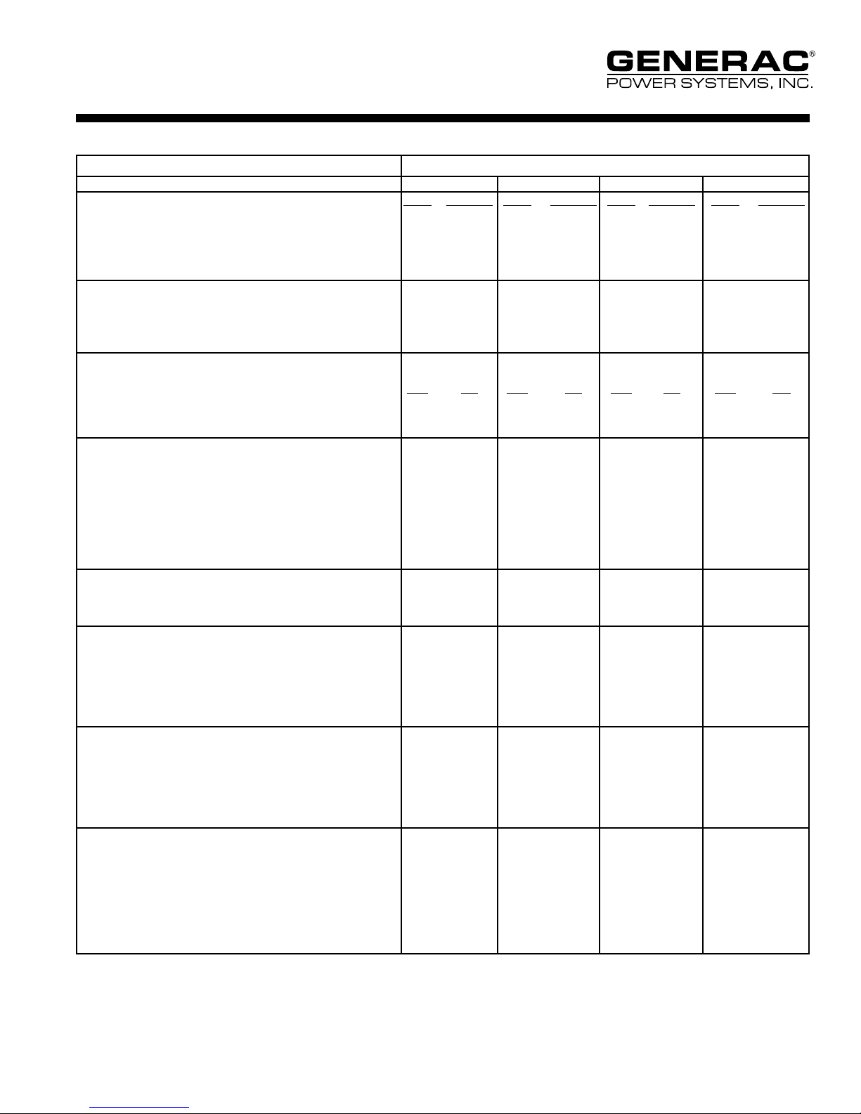
SG010
SG015
Standby Power Rating
10KW 60 Hz
15KW 60 Hz
Liquid Cooled Gas Engine Generator Sets
Prime Power Rating
7.2KW 60 Hz
11KW 60 Hz
Power Matched
GENERAC MMC 4G15 ENGINE
Naturally Aspirated
FEATURES
■ INNOVATIV E DESIGN & PROTOTYPE TESTING are key
components of GENERAC'S success in "IMPROVING POWER BY
DESIGN." But it doesn't stop there. Total commitment to component
testing, reliability testing, environmental testing, destruction and life
testing, plus testing to applicable CSA, NEMA, EGSA, and other
standards, allows you to choose GENERAC POWER SYSTEMS
with the confidence that these systems will provide superior
performance.
■ TEST CRITERIA:
✓ PROTOTYPE TESTED
✓ SYSTEM TORSIONAL TESTED
✓ ELECTRO-MAGNETIC INTERFERENCE
✓ NEMA MG1 EVALUATION
✓ MOTOR STARTING ABILITY
✓ SHORT CIRCUIT TESTING
✓ UL 2200 COMPLIANCE AVAILABLE
■ SOLID-STATE, FREQU EN CY COMPENSATED VOLTAGE
REGULATION. This state-of-the-art power maximizing regulation
system is standard on all Generac models. It provides optimized
FAST RESPONSE to changing load conditions and MAXIMUM
MOTOR STARTING CAPABILITY by electronically torque-matching
the surge loads to the engine.
■ SINGLE SOURCE SERVICE RESPONSE from Generac's dealer
network provides parts and service know-how for the entire unit,
from the engine to the smallest electronic component. You are never
on your own when you own a GENERAC POWER SYSTEM.
■ GEN ERAC TRANS FER SWITC HES, SWITC HGEAR AND
ACCESSORIES. Long life and reliability is synonymous with
GENERAC POWER SYSTEMS. One reason for this confidence is
that the GENERAC product line includes its own transfer systems,
accessories, switchgear and controls for total system compatibility.
Page 2

APPLICATION
& ENGINEERING DATA
SG010 / SG015
GENERATOR SPECIFICATIONS
TYPE ................................................................. Two-pole, revolving field
ROTOR INSULATION ..................................................................Class F
STATOR INSULATION .................................................................Class F
TOTAL HARMONIC DISTORTION ..................................................
TELEPHONE INTERFERENCE FACTOR (TIF) ................................
ALTERNATOR ...........................................Self-ventilated and drip-proof
BEARINGS (PRE-LUBED & SEALED) .................................................1
COUPLING .............................................................. Direct, Flexible Disc
LOAD CAPACITY (STANDBY) .......................................................100%
NOTE: Emergency loading in compliance with NFPA 99, NFPA
110, paragraph 5-13.2.6. Generator rating and performance in
accordance with ISO8528-5, BS5514, SAE J1349, ISO3046 and
DIN6271 standards.
EXCITATION SYSTEM
DIRECT ............................................................. DC excitation system ✓
Low-velocity brushes and slip rings ✓
REGULATION ................................................................... Solid-state ✓
.................................................................................... +2% regulation ✓
<5%
<50
GENERATOR FEATURES
ENGINE SPECIFICATIONS
MAKE .................................................................................... GENERAC
MODEL ................................................................................. MMC 4G15
CYLINDERS ............................................................................... 4 in-line
DISPLACEMENT ................................................... 1.5 Liter (91.5 cu. in.)
BORE .........................................................................75.5 mm (2.97 in.)
STROKE ........................................................................82 mm (3.23 in.)
COMPRESSION RATIO ..................................................................9.4:1
INTAKE AIR ...............................................................Naturally Aspirated
NUMBER OF MAIN BEARINGS ...........................................................5
CONNECTING RODS .............................................. 4-Drop forged steel
CYLINDER HEAD .....................................................................S.O.H.C.
PISTONS ..................................................................... 4-Aluminum Alloy
CRANKSHAFT ...........................................................Drop Forged Steel
VALVE TRAIN
LIFTER TYPE ...............................................................Rocker Arm Type
INTAKE VALVE MATERIAL .....................High Temperature Alloy Forged
EXHAUST VALVE MATERIAL ................High Temperature Alloy Forged
VALVE SEATS ..................................................................... Replaceable
ENGINE GOVERNOR
❐ ELECTRONIC ...................................................................... Standard
FREQUENCY REGULATION, NO-LOAD TO FULL LOAD
STEADY STATE REGULATION ...............................................+0.25%
... Isochronous
■ Four pole, revolving field generator, directly connected to the engine
shaft through a heavy-duty, flexible disc for permanent alignment.
■ Generator meets the temperature rise standards for class "F"
insulation as defined by NEMA MG1-32.6.
■ All prototype models have passed a three-phase symmetrical short
circuit test to assure system protection and reliability.
■ All prototype models are tested for motor starting ability by
measuring the instantaneous voltage dip with a waveform data
acquisition system.
■ All models utilize an advanced wire harness design for reliable
interconnection within the circuitry.
■ Magnetic circuit, including skewed stator design, provides a minimal
level of waveform distortion and an electromagnetic interference
level which meets accepted requirements for standard AM radio, TV,
and marine radio telephone applications.
■ Voltage waveform deviation, total harmonic content of the AC
waveform, and T.I.F. (Telephone Influence Factor) have been
evaluated to acceptable standards in accordance with NEMA
MG1-32.
■ Alternator is self-ventilated and drip-proof constructed.
■ Fully life-tested protective systems, including "field circuit and
thermal overload protection" and optional main-line circuit breakers
capable of handling full output capacity.
■ System Torsional acceptability confirmed during Prototype Testing.
■ Generac H-100 Digital Control Panel
LUBRICATION SYSTEM
TYPE OF OIL PUMP .......................................................................Gear
OIL FILTER .................................................................Full flow, cartridge
CRANKCASE CAPACITY ............................................. 3.8 Liters (4 qts.)
COOLING SYSTEM
TYPE OF SYSTEM ...................................Pressurized, closed recovery
WATER PUMP ..................................................... Pre-lubed, self-sealing
TYPE OF FAN ............................................................................. Pusher
NUMBER OF FAN BLADES ..................................................................6
DIAMETER OF FAN ....................................................380 mm (15.0 in.)
COOLANT HEATER ............................................................120V, 500 W
FUEL SYSTEM
FUEL
❐ Natural Gas or L.P. Vapor ................................................. Standard
❐ L.P. Liquid Withdrawal ........................................................ Optional
CARBURETOR .......................................................................Down draft
SECONDARY FUEL REGULATOR ....... Nat. Gas or L.P. Vapor Systems
HOT WATER VAPORIZER..................... L.P. Liquid Withdrawal Systems
AUTOMATIC FUEL LOCKOFF SOLENOID.............................. Standard
OPERATING FUEL PRESSURE VAPOR SYSTEMS ........7" to 15" H2O
ELECTRICAL SYSTEM
BATTERY CHARGE ALTERNATOR ............................. 15 Amps at 12 V
STARTER MOTOR ...........................................................................12 V
RECOMMENDED BATTERY ............................(1) - 12 V, 530 CCA, 26F
GROUND POLARITY ................................................................Negative
Rating definitions - Standby: Applicable for supplying emergency power for the duration of the utility power outage. No overload capability is available for this rating. (All ratings in accordance with
BS5514, ISO3046 and DIN6271). Prime (Unlimited Running Time): Applicable for supplying electric power in lieu of commercially purchased power. Prime power is the maximum power available at
variable load. A 10% overload capacity is available for 1 hour in 12 hours. (All ratings in accordance with BS5514, ISO3046, ISO8528 and DIN6271).
Page 3
SG010 / SG015
OPERATING DATA
STANDBY PRIME
SG010 SG015 SG010 SG015
GENERATOR OUTPUT VOLTAGE/KW-60Hz NG/LP Rated AMP NG/LP Rated AMP NG/LP Rated AMP NG/LP Rated AMP
120/240V, 1-phase, 1.0 pf 10 41.7 15 62.5 7.2 30.0 11 45.8
120/208V, 3-phase, 0.8 pf 10 34.7 15 52.1 7.2 25.0 11 38.2
120/240V, 3-phase, 0.8 pf 10 30.1 15 45.2 7.2 21.7 11 33.1
277/480V, 3-phase, 0.8 pf 10 15.1 15 22.6 7.2 10.8 11 16.6
MOTOR STARTING KVA
Maximum at 35% instantaneous voltage dip
with standard alternator; 60 Hz 20 29 20 29
FUEL
Fuel consumption—60 Hz—100% Load N.G. L.P. N.G. L.P. N.G. L.P. N.G. L.P.
ft.3/hr. 185 77 265 110 145 60 204 85
m3/hr. 5.2 2.2 7.5 3.1 4.1 1.7 5.8 2.4
COOLING
Coolant capacity System lit.(US gal.) 6.6 (1.75) 6.6 (1.75) 6.6 (1.75) 6.6 (1.75)
Engine lit.(US gal.) 0.9 (0.25) 0.9 (0.25) 0.9 (0.25) 0.9 (0.25)
Radiator lit.(US gal.) 6.6 (1.75) 6.6 (1.75) 6.6 (1.75) 6.6 (1.75)
Coolant flow/min. 60 Hz lit.(US gal.) 25 (6.6) 25 (6.6) 25 (6.6) 25 (6.6)
Heat rejection to coolant 60 Hz BTU/hr. 48,000 72,000 35,000 53,000
Cooling air flow 60 Hz m
3
/min. (cfm) 40 (883) 40 (883) 40 (883) 40 (883)
COMBUSTION AIR REQUIREMENTS
Flow at rated power 60 Hz m
EXHAUST
Exhaust flow at rated output 60 Hz m
3
/min. (cfm) 0.8 (29) 1.2 (41) 0.6 (22) 0.9 (32)
3
/min. (cfm) 2.7 (96) 3.9 (137) 2.1 (75) 3.0 (32)
Max. recommended back pressure Kpa (Hg) 5.0 (1.5") 5.0 (1.5") 5.0 (1.5") 5.0 (1.5")
Exhaust temp. at rated output oC (oF) 593 (1100) 621 (1150) 566 (1050) 593 (1100)
Exhaust outlet size N.P.T. (female) 1.5" 1.5" 1.5" 1.5"
ENGINE
Rated RPM 60 Hz 1800 1800 1800 1800
HP at rated KW 60 Hz 15 23 11 17
Piston speed 60 Hz m/min. (ft./min.) 295 (969) 295 (969) 295 (969) 295 (969)
BMEP (psi) 60 Hz - psi 77 116 55 85
POWER ADJUSTMENT FOR AMBIENT CONDITIONS
Temperature
-3% for every 10
o
C above - °C 40 25 40 25
-1.5% for every 10oF above - °F 104 77 104 77
Altitude
-3% for every 300 m above - m 913 150 913 150
-3% for every 1000 ft. above - ft. 3000 500 3000 500
Page 4
STANDARD ENGINE & SAFETY FEATURES
SG010 / SG015
■ High Coolant Temperature Automatic Shutdown
■ Low Coolant Level Automatic Shutdown
■ Low Oil Pressure Automatic Shutdown
■ Overspeed Automatic Shutdown (Solid-state)
■ Crank Limiter (Solid-state)
■ Oil Drain Extension
■ Radiator Drain Extension
■ Factory-Installed Cool Flow Radiator
■ Closed Coolant Recovery System
■ UV/Ozone Resistant Hoses
■ Rubber-Booted Engine Electrical Connections
■ Isochronous Governor
■ Fuel Lockoff Solenoid
■ Low Coolant Temperature
OPTIONS
■ OPTIONAL FUEL ACCESSORIES
❍ Flexible Fuel Lines
❍ L.P. Liquid Withdrawal
❍ Automatic Gaseous Dual Fuel
■ OPTIONAL EXHAUST ACCESSORIES
❍ Critical Exhaust Silencer
■ OPTIONAL ELECTRICAL ACCESSORIES
❍ Battery, 12 Volt, 75 A.H., 27F
❍ Battery Heater
❍ 2A Battery Charger
❍ 10A Dual Rate Battery Charger
■ Secondary Fuel Regulator (N.G. and L.P.)
■ Low Fuel Pressure Alarm
■ Stainless Steel Flexible Exhaust Connection
■ Battery Charge Alternator
■ Battery Cables
■ Battery Tray
■ Vibration Isolation of Unit to Mounting Base
■ 12 Volt, Solenoid-Activated Starter Motor
■ Air Cleaner
■ Fan Guard
■ Control Console
■ Radiator Duct Adapter
❍ Oil Make-Up System
❍ Oil Heater
❍ 5 Year Warranties
❍ Export Boxing
❍ Heavy Duty Air Cleaner
❍ Engine Block Heater
■ OPTIONAL ENCLOSURE
❍ Weather Protective
❍ Sound Attenuated
❍ Alluminum
❍ Enclosed Muffler
■ OPTIONAL ALTERNATOR ACCESSORIES
❍ Alternator Strip Heater
❍ Alternator Tropicalization
❍ Main Line Circuit Breaker
■ CONTROL CONSOLE OPTIONS
• see Digital Controller H-100 specification 0172110SBY
■ ADDITIONAL OPTIONAL EQUIPMENT
❍ Automatic Transfer Switch
❍ 20 Light Remote Annunciator
❍ Alarm Relay Panels
❍ Unit Vibration Isolators (Pad/Spring)
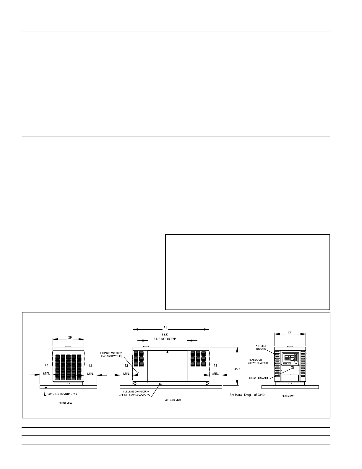
Design and specifications subject to change without notice. Dimensions shown are approximate. Contact your Generac dealer for certified drawings. DO NOT USE THESE DIMENSIONS FOR INSTALLATION PURPOSES.
Distributed by:
mm [in]
GENERAC® POWER SYSTEMS, INC. • P.O. BOX 8 • WAUKESHA, WI 53187
262/544-4811 • FAX 262/544-4851
Bulletin 0172500SBY / Printed in USA 12.05, rev: 01.06
WEIGHT: 1650 lbs.
© 2006 Generac Power Systems, Inc. All rights reser ved. All specifications subject to change without notice.
 Loading...