

Page 1
INSTALLATION GUIDE
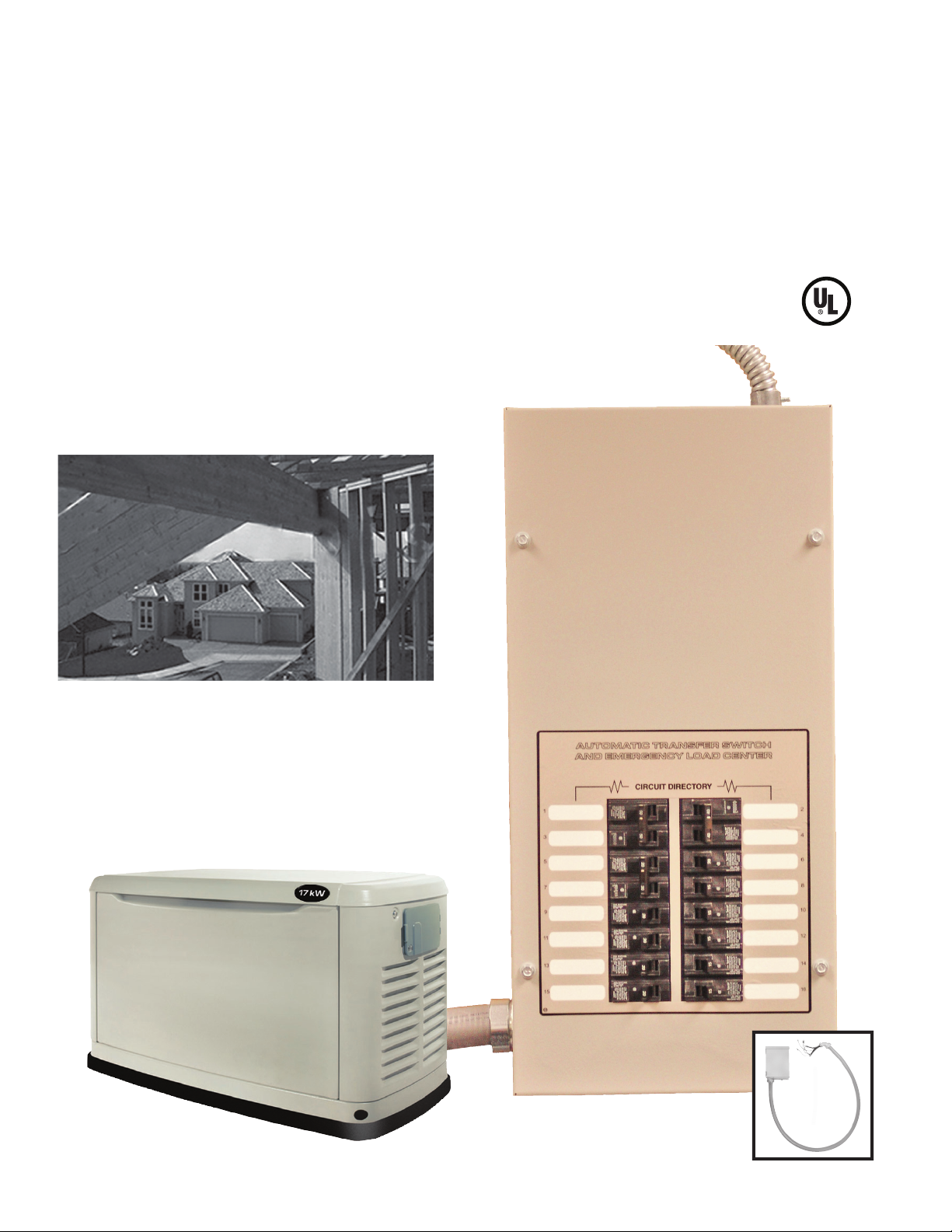
For 100 Amp Automatic Transfer Switch/Load Center Models:
10, 12, 14 and 16 Circuit.
Installed with 8, 10, 12, 14, 16 and 17kW Generators.
This Automatic Transfer Switch with built-in
Load Center includes an Express Install Kit.
C
US
• Saves on installation time and cost, in many
cases up to 50% compared to traditional
transfer switch installations.
• Automatically supplies electricity to
selected critical circuits.
LISTED
• Can be installed prior to, or along with
generator installation.
This manual should remain with the unit.
Page 2

Table of Contents
INSTALLATION GUIDE
INSTALLATION DRAWINGS/WIRING DIAGRAMS/EXPLODED VIEWS ......................................................................8
NOTES ...................................................................................................................................................................16
GUÍA DE INSTALACIÓN .........................................................................................................................................19
GUIDE D'INSTALLATION ........................................................................................................................................29
Page 3
Residential Transfer Switch Installation Guide
PLEASE NOTE:
This installation guide should be used in conjunction with the “Installation and Owner’s Manual” that is furnished with the Air-cooled Standby Generator. Please review both manuals prior to installation of the
generator and transfer switch. This Automatic Transfer Switch/Load Center is not intended for use with the
Liquid-cooled Generator product line. This unit is not compatible with other generator manufacturer’s products.
INTRODUCTION
Thank you for purchasing this 100 Amp Automatic Transfer
Switch/Load Center with Express Install Kit. The Express Install
Kit includes:
• 30 foot, five foot, and two foot pre-wired conduits for making all
required wiring runs.
• An outdoor junction box for making connections between outdoor and indoor pre-wired conduits.
• UL listed wire nuts for reconnecting emergency circuits within
the main distribution panel.
The 100 Amp Automatic Transfer Switch/Load Center with Express
Install Kit can be installed along with a 8, 10, 12, 14, 16 or 17kW
Air-cooled Standby Generator, or can be used to pre-wire a home
or small business in advance of generator installation. In either
case, the Express Install Kit saves installation time and cost, since
the majority of labor involved in installing a standby power system
is in wiring the generator, automatic transfer switch and emergency circuit subpanel.
Four commonly used safety symbols accompany the DANGER,
WARNING and CAUTION blocks. The type of information each
indicates follows:
Indicates a hazardous situation or action which, if
not avoided, will result in death or serious injury.
Four commonly used safety symbols accompany the DANGER,
WARNING and CAUTION blocks. The type of information each
indicates is as follows:
This symbol points out important safety
n
information that, if not followed, could
endanger personal safety and/or property of
others.
This symbol points out potential explosion
hazard.
This symbol points out potential fire hazard.
This symbol points out potential electrical
shock hazard.
SAVE THESE INSTRUCTIONS – The manufacturer sug-
gests that these rules for safe operation be copied and
n
posted near the unit’s installation site. Safety should be
stressed to all operators and potential operators of this
equipment.
The manufacturer cannot anticipate every possible circumstance
that might involve a hazard. The warnings in this manual, and on
tags and decals affixed to the unit are therefore, not all-inclusive. If
using a procedure, work method or operating technique the manufacturer does not specifically recommend, ensure that it is safe for
all personnel. Also make sure the procedure, work method or operating technique chosen does not render the equipment unsafe.
Indicates a hazardous situation or action which,
if not avoided, could result in death or serious
injury.
Indicates a hazardous situation or action which,
if not avoided, could result in minor or moderate
injury.
NOTE:
Notes contain additional information important to a procedure
and will be found within the regular text body of this manual.
These safety warnings cannot eliminate the hazards that they
indicate. Common sense and strict compliance with the special
instructions while performing the action or service are essential to
preventing accidents.
ELECTRICAL HAZARDS
• Utility power delivers extremely high and dangerous voltages to
the transfer switch as does the standby generator when it is in
operation.
• Do not handle any kind of electrical device while standing in water, while barefoot, or while hands or feet are wet.
DANGEROUS ELECTRICAL SHOCK MAY RESULT.
• In case of accident caused by electric shock, immediately
shut down the source of electrical power. If this is not possible, attempt to free the victim from the live conductor. AVOID
DIRECT CONTACT WITH THE VICTIM. Use a non-conducting
implement, such as a rope or board, to free the victim from the
live conductor. If the victim is unconscious, apply first aid and
get immediate medical help.
• Never wear jewelry when working on this equipment. Jewelry
can conduct electricity resulting in electric shock, or may get
caught in moving components causing injury.
1
Page 4
Residential Transfer Switch Installation Guide
100 Amp Automatic Transfer Switch/Load Center with Express Install Kit
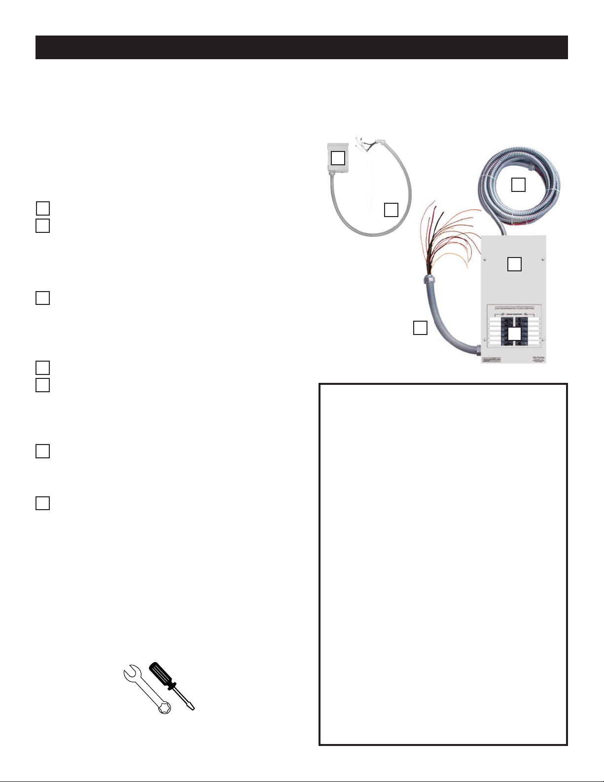
KIT INCLUDES:
THE OUTDOOR CONNECTION BOX WITH FIVE FOOT
A
PRE-WIRED LIQUID TIGHT CONDUIT
B
Mounted outside the home or business nearest the
planned generator location. This is for connection to
generator controls and main line circuit breaker.
30 FOOT FLEXIBLE CONDUIT
C
Pre-wired from the automatic transfer switch with built-
in emergency load center for connection to the outdoor
connection box.
PRE-WIRED AUTOMATIC TRANSFER SWITCH AND
D
EMERGENCY LOAD CENTER
E
Installed within one (1) foot of the building’s main distri-
bution panel. This transfer switch provides smooth and
safe transition between utility and generator power.
Designed with installation
cost savings in mind!
A
C
B
D
F
ITEMS TO BE PURCHASED OR SUPPLIED FOR
COMPLETE INSTALLATION:
E
TWO FOOT PRE-WIRED CONDUIT FOR EASY
F
CONNECTION TO THE BUILDING’S MAIN
DISTRIBUTION PANEL
UL LISTED WIRE NUTS (not shown)
G
TOOLS REQUIRED:
Drill, drill bits, hole saw (type and length will be determined by the materials to be drilled and cut), open-end
wrenches or adjustable wrenches, socket wrenches or
nut drivers, standard and Phillips screwdrivers, sledge
hammer, level, pencil, channel-lock pliers, spade shovel, rake and safety goggles.
2
; 70 amp or 40 amp (8kW) double pole circuit breaker
(must be the same type as in the main electrical
distribution panel)
; Ground rod with grounding strap (for generator
installation)
; Padlock to lock outdoor connection box
; Crushed stone or pea gravel (approximately 10-12
cubic feet) (for generator installation)
; Black poly-film or other vegetation blocking fabric
(for generator installation)
; Silicone caulk
; Fasteners (to mount outdoor connection box and
automatic transfer switch)
; Battery - 12V automotive type, group 26R, negative
ground, 350 CCA (8kW), 525 CCA (10, 12, 13, 14,
16, 17 and 20kW) minimum capacity (required
as part of generator installation).
Page 5
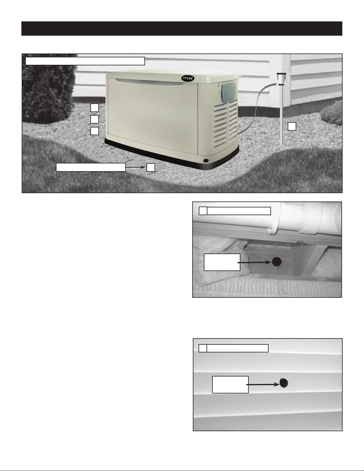
Site Preparation and Standby Generator Placement
1
2
3
Residential Transfer Switch Installation Guide
5
Crushed Stone or Pea Gravel
4
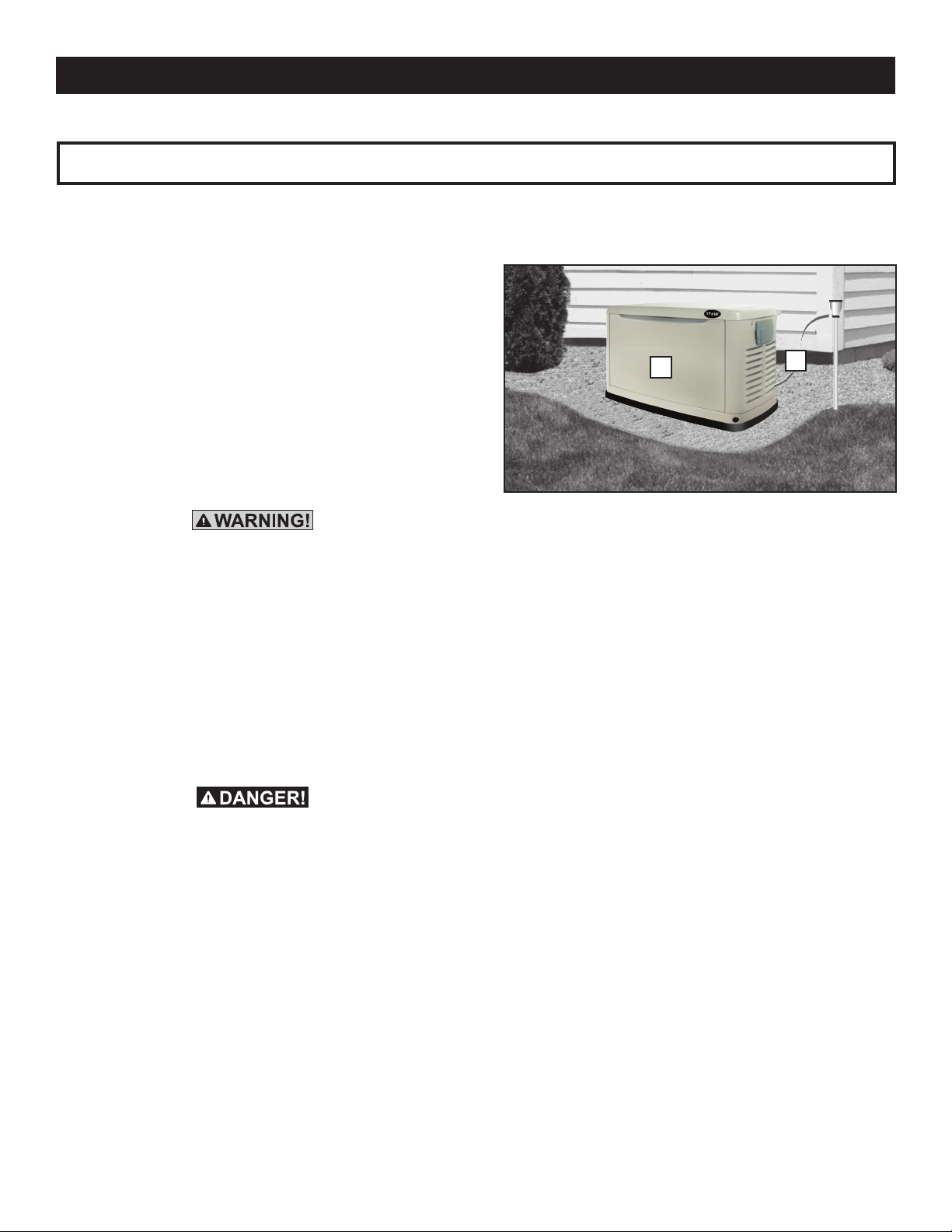
1. PLAN THE LOCATION OF THE GENERATOR.
NOTE:
Do not place the generator directly under a window.
Select an area outside of the home or business nearest
the incoming gas service. Determine where the generator will be placed outside of the building. Arrange for fuel
piping with shut-off valve to be run to this location. Keep
in mind that the manufacturer recommends placement
no closer than 18 inches to any structure. Local codes
may dictate placement farther from a structure. If
facing the unit from the front, the generator's fuel inlet is
located at the rear lower right of the unit.
2. Clear an area 62 inches by 50 inches of grass and veg-
etation to a depth of five inches. This includes the distance the generator should be set away from a structure
(18 inches) and six inches beyond the width and length
of the generator mounting pad (49" L x 25" W).
Drill Hole Through House
6
1-3/4”
Diameter Hole
7. While adhering to all local electrical codes, route the 30
foot conduit along ceiling/floor joists and wall studs to
the location where the conduit will pass through the wall
to the exterior of the building.
3. Lay black poly-film to cover the area.
4. Fill the area to ground level with pea gravel or crushed
stone.
5. Drive an eight foot grounding rod into the ground to
grade. Make sure grounding rod and strap are not
exposed above ground level. (NEC code applies to
grounding method.)
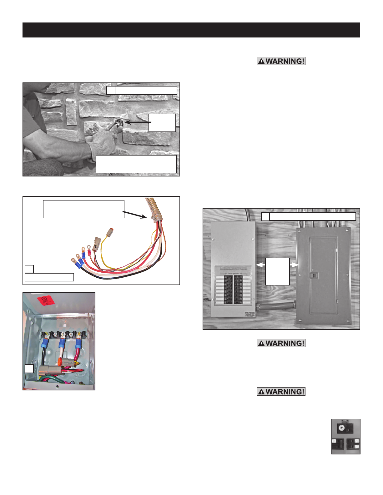
6. Determine where the flexible conduit will pass through
the building from inside to outside. When certain there
is clearance on each side of the wall, drill a small pilot
hole through the wall to mark the location. Drill a 1-3/4”
diameter hole through the sheathing and siding with hole
saw.
Drill Pass Through Hole
7
1-3/4”
Diameter Hole
3
Page 6
Residential Transfer Switch Installation Guide
8. From inside the building, feed the end of the 30-foot
conduit (INCLUDED and pre-wired from transfer switch)
through the wall to the outside.
n
Feed Conduit and Wires
8
Silicone
Caulk
The outer diameter of the conduit
connector is 1-11/16”
9. Remove the threaded lock nut from the conduit coupling.
The outer diameter of the threaded
end is 15/16 inches.
11. Locate automatic transfer switch with built-in emer-
The outdoor connection box must be locked to
ensure safety and to discourage tampering.
gency load center in close proximity to the main
distribution panel. The transfer switch can be located
to the left or right of the main distribution panel. Two
(2) feet is the suggested distance (see Figure 11). The
transfer switch may be located a different distance
from the main panel depending on available mounting
area. Using the two (2) foot conduit connected straight
across to the main panel is another option. Always
adhere to local electrical codes during installation. Hold
transfer switch against the mounting surface. Level the
transfer switch and mark the mounting holes. Drill the
appropriate size pilot holes. Mount transfer switch with
built-in load center to mounting surface with appropriate fasteners.
Mounting Automatic Transfer Switch
11
9
Threaded Lock Nut
10. Lift cover. Remove internal
cover plate screw and internal
cover. Remove the knock out
in the lower right corner of
the external connection box.
From the rear of the connection box, feed wires, 4-pin and
2-pin plugs into box. Slip the
lock nut over wires and plugs
10
and tighten securely onto conduit coupling. Using appropriate fasteners, mount external
connection box over pre-drilled
hole to fully conceal the hole. Seal around the hole and
conduit with silicone caulk from both the inside and outside of the building. Also, caulk around the sides and top
of the box to seal the edges to the siding or wall. Connect
wires to lugs; black to black, white to white, and red to red.
Torque nuts to 20 in/lbs. Snap together the 4-pin and 2-pin
plug connector. Loosen nut from grounding lug and attach
ground wire (green) from conduit. Reinstall nut and tighten
to 45 in/lbs. Reinstall internal cover plate and screw. Close
cover and install lock. This wiring is complete.
4
Two (2)
Feet
Suggested
Distance
The manufacturer recommends that a licensed electrician or an individual with complete knowledge of
electricity perform the procedures in Sections 12
and 13.
Switch service main circuit breaker to the OFF (OPEN)
position prior to removal of cover or removal of any
wiring of the main electrical distribution
panel. The wires connected to the service
main circuit breaker remain LIVE or HOT.
Avoid contact with these wires and the
service main circuit breaker connection
lugs.
OFF
Page 7
Residential Transfer Switch Installation Guide
NOTE:
Balance must be maintained when moving circuit locations from main electrical distribution panel to emergency
load center. Circuit breaker positions alternate buss bars
vertically. Circuits sharing a neutral wire should either be
moved together to adjacent positions in emergency load
center or not moved. If unsure of the proper procedure or
if the installation differs from that described in this guide,
consult a licensed professional at this time.
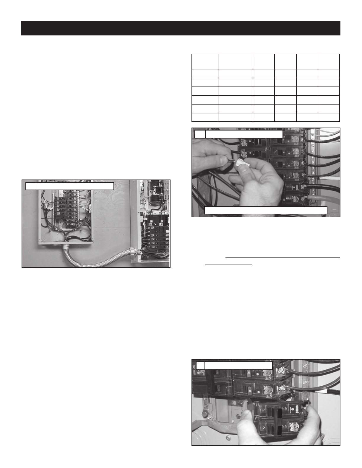
12a. Remove the main electrical distribution panel cover.
Remove appropriate size knockout from the bottom
or side of the main panel. (A two foot flexible conduit
is pre-wired from the transfer switch with built-in load
center). Remove threaded lock nut from conduit coupling. Feed all wires through knockout into main panel.
Slip lock nut over wires and tighten securely onto conduit coupling.
Connection of Emergency Circuits
12a
NOTE:
Circuits to be moved must be protected by same size
breaker. For example, a 15 amp 120 volt circuit in emergency load center will replace a 15 amp 120 volt circuit
in main electrical distribution panel.
12b. In the main panel, remove the black (hot) wire from
the circuit breaker that protects a circuit to be powered
in the event of a power failure. Wire nut the black wire
to the matching circuit lead wire from the emergency
circuit breaker in the load center in the transfer switch.
(All circuit wires are color coded and labeled for easy
identification). UL listed wire locknuts are included in
installation kit. Trace each black (hot) wire connected
and wire nut the white (neutral) wire from the same
Romex cable (circuit) to the matching circuit number
on the white (neutral) wire from the emergency load
center. Repeat for each circuit. Repeat this process
with the remaining circuits to be powered by the generator.
NOTE:
Models
Circuits 50A, 240V - - - 1
40A, 240V - 1 1 1
30A, 240V 1 1 - 20A, 240V 1 - 1 1
20A, 120V 3365
15A, 120V 3545
Connection of Emergency Circuits
12b
UL approved wire nuts are included with installation kit.
10
Circuit
12
Circuit
14
Circuit
16
Circuit
13. Install the 70 amp double pole circuit breaker; 10, 13,
14, 16, and 17kW units or the 40 amp double pole
breaker; 8kW units (purchased or supplied separately),
into main electrical distribution panel. This circuit
breaker must be compatible with the main electrical
distribution panel. It may be necessary to reposition
remaining circuit breakers or remove circuit breakers
that have been disconnected to accommodate the
insertion of the 70 amp or 40 amp double pole circuit
breaker. Connect white wire to the main distribution
panel neutral bar. Connect solid green wire to main
electrical panel ground bar. Connect the black and red
wires to the 70 amp or 40 amp double pole circuit
breaker. Reinstall the main distribution panel cover.
If a generator is being installed at this time, proceed
to step 19. If a generator will not be installed at this
time, perform steps 14 through 17 to complete the
pre-wiring project.
Install 70 Amp Circuit Breaker
13
70
Both grounded and ungrounded conductors must be moved
to the emergency panel and connected to the new wiring
from the emergency panel using supplied wire nuts.
70
5
Page 8
Residential Transfer Switch Installation Guide
THE AUTOMATIC TRANSFER SWITCH/LOAD CENTER IS NOW INSTALLED!
14. Open the outdoor connection box and unplug the 4-pin
and 2-pin connector. Remove the black, white, red,
and green wires that lead from the five foot pre-wired
conduit. Make sure the mating wires from the 30 foot
conduit are on the connection box terminal lugs (or
ground screw), re-install all washers and nuts and
secure them in place.
15. Remove the lock nut holding the five foot pre-wired
conduit coupling to the outdoor connection box. Slip
the lock nut over the wires and plug, then remove
the conduit from the connection box. Use a knockout
plug to close off the opening where the conduit was
removed.
The external connection box must be locked to
n
ensure safety and to discourage tampering.
16. For pre-existing buildings, switch the service main
circuit breaker back on to provide utility power to the
building.
17. Save the five foot pre-wired conduit for re-installation
at time of generator installation. At that time, re-install
the conduit by reversing steps 14 and 15. The grounding strap will also be installed with the generator. Save
this guide for reference at time of generator installation.
Be sure the service main circuit breaker is switched
OFF at time of generator installation.
This completes the pre-wiring portion of the 100 Amp
Automatic Transfer Switch/Load Center Installation.
Proceed with step 18 for generator installation.
18. Place the generator and mounting pad in the location
prepared in steps one through five.
18
19. Attach one end of the grounding strap (No. 12 AWG
stranded copper wire) to grounding rod, and the other
end to the grounding lug (located at rear corner of
unit). Make sure the grounding rod and strap are not
exposed above ground level (NEC code applies to
grounding method).
NOTE:
The generator mode switch should be placed in the OFF
position. Generator main line circuit breaker should be
switched to the OFF or OPEN position.
20. Access wiring connections for installation of five foot
harness at the generator. To gain access to wiring connections and the circuit breaker you must remove the
cover plate (black) over the control module. Remove
the two screws retaining the cover plate. Lift the cover
plate up and towards the front of the generator to
remove.
Remove the small black cap (covering 1-1/16” diam-
eter hole) from back of enclosure. Remove threaded
lock nut from conduit coupling (with 90° elbow) and
wires. Feed wires into 1-1/16” diameter hole. Place
threaded lock nut over wires and onto conduit coupling. Tighten securely with screwdriver and hammer
to ensure lock nut is tight. Connect power leads (red
& black) to the circuit breaker lugs. Connect the neutral wire (white) to terminal bar labeled "NEUTRAL".
Connect the ground wire (green) to terminal bar labeled
"GROUND". Connect sensing wires to terminal strips
as follows: Yellow - N1, Yellow - N2, Blue - T1 / White
- 23, Red - 194.
19
6
Page 9
Residential Transfer Switch Installation Guide
FUEL HOOKUP AND CHECK FOR LEAKS
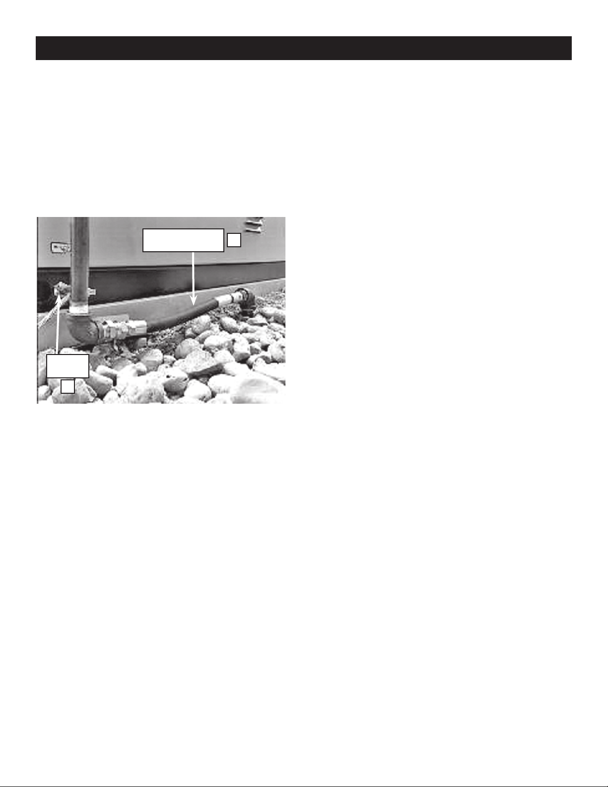
21a. Make the connection between the rigid fuel piping
and the generator using the supplied threaded flexible
fuel line. Use a pipe sealant suitable for gaseous fuel
connections. Check connections for leaks by opening
manual fuel shut-off valve and swab, or spray, connections with soapy water. If a leak exists, the area will
bubble with the presence of the soapy water.
One (1) Foot Flexible
Fuel Line
Grounding
Lug
21
21b. If a leak is located, shut off fuel and disconnect flex-
ible piping. Dry the threaded ends and reapply an
adequate amount of pipe sealant. Reconnect flexible
fuel line, open fuel supply and recheck for leaks. If
leak still exists, repeat step 21b.
22. Follow all generator installation and setup instructions
in the Installation and Owner’s Manual provided with
the generator. During testing performed in Section 2 of
the generator Installation and Owner’s Manual, utility
power supply to the Automatic Transfer Switch/Load
Center can be controlled using the 40 or 70 amp feeder
circuit breaker located in the main distribution panel.
19
7
Page 10
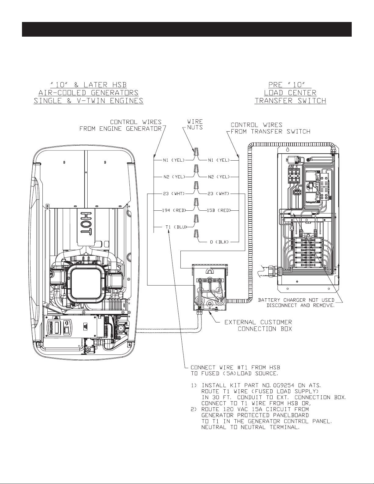
Installation Drawing 0H6393-A
8
Page 11
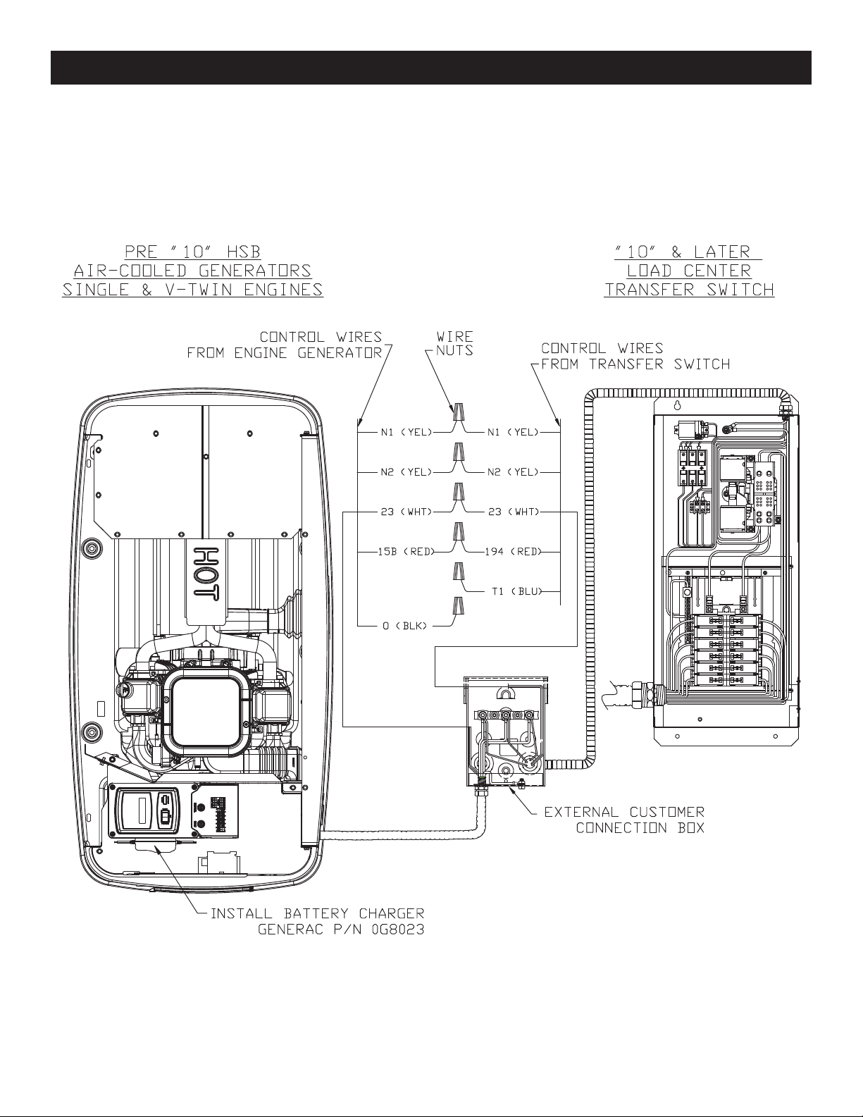
Installation Drawing 0H6393-A
9
Page 12
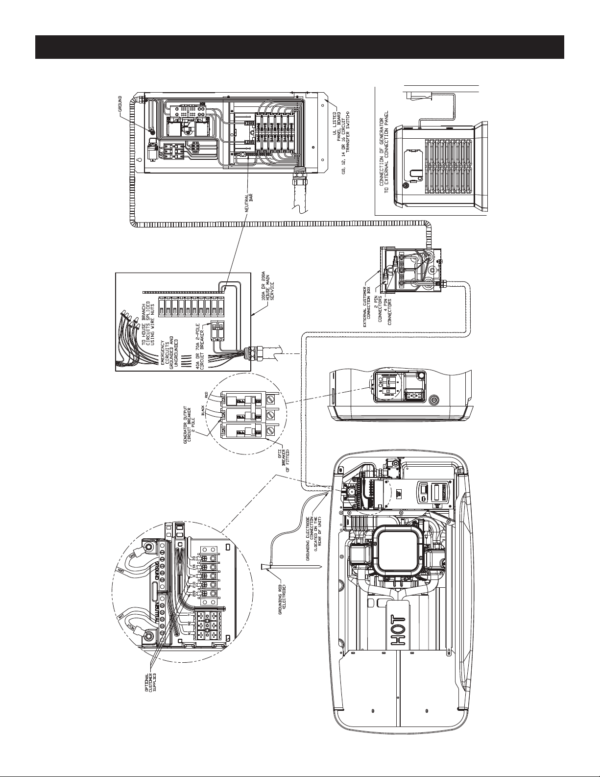
Installation Drawing 0H6392-B
10 10
Page 13

Electrical Schematic Drawing 0H6386-B
11
Page 14

Wiring Diagram Drawing 0H6385-A
12
Page 15

Wiring Diagram Drawing 0H6385-A
13
Page 16

Load Center Exploded View Drawing 0H6388-A
14
Page 17

Load Center Exploded View Drawing 0H6388-A
ITEM PART NO. QTY. DESCRIPTION
1 0G80700ST14 1 GTS LOAD CENTER ENCLOSURE GRAY
2 0G81020ST14 1 COVER 10 POS.GTS LOAD CTR GRAY
0G81030ST14 1 COVER 12 POS.GTS LOAD CTR GRAY
0G81040ST14 1 COVER 14 POS.GTS LOAD CTR GRAY
0G81060ST14 1 COVER 16 POS.GTS LOAD CTR GRAY
3 0C2237 1 TRANSFER SWITCH HOME STANDBY 100A 2P 250V
3A 077220 1 COIL UTILITY
3B 077220A 1 COIL STANDBY
4 074908 4 SCREW HHTT M5-0.8 X 10
5 024912 1 SCREW TAPTITE 1/4-20 X 5/8
6 0A1658 1 LOCK WASHER, SPECIAL-1/4”
7 063617 1 RELAY PANEL 12VDC DPDT 10A@240VAC
8 0E7889 1 12CIR L/CENTR 125A/240V (ALSO USED FOR 10 CIRCUIT)
0F9213 1 16CIR L/CENTR 125A/240V (ALSO USED FOR 14 CIRCUIT)
9 0A1495 4 SCREW HHTT M4-0.7 X 10
10 0A1661 2 RIVET POP .156” X .675”
11 081108 1 PLUG PLASTIC
12 0G8095AST14 1 HARNESS ADAPTER PLATE GRAY
13 0G81300ST14 1 SUBPLATE GTS LOAD CENTER GRAY
14 0F4790 5.28” U-CHANNEL
15 023897 6 WASHER FLAT #10 ZINC
16 022717A 1 GROMMET 3/8 X 1/16 X 1/4
17 0E6155 1 ARM EXTENDER PIN
18 0G8233A 4 CABLE TIE SELF MOUNTING 4.3LG
19 0G8139 1 HARN GTS-MAIN PNL 10CIR W/NEUT
0G8140 1 HARN GTS-MAIN PNL 12CIR W/NEUT
0H6394 1 HARN GTS-MAIN PNL 14CIR W/NEUT
0G8141 1 HARN GTS-MAIN PNL 16CIR W/NEUT
20 074138 3 LUG QUICK DISCONNECT NI-S 10X45 DEG BRASS / TIN
21 036933 6 SCREW PPHM #10-32X3/8
22 077033 6 LUG SLDLSS 1/0-#14X9/16 AL/CU
23 048766 1 BLOCK TERM 20A 2 X 6 X 1100V
24 022152 6 WASHER LOCK #10
25 0A7215 10 SCREW SW 1/4"-20 X 5/8” WITH WASHER
26 066849 2 SCREW HHTT M5-0.8 X 16 (10, 12, 14, 16 CIRCUIT)
27 0H6399A 1 HARNESS LOAD CTR INT.CONN 10-16 (NOT SHOWN)
0H6399B 1 HARNESS LOAD CTR INT.CONN T1 (NOT SHOWN)
0H6399C 1 HARNESS LOAD CTR INT.CONN T2 (NOT SHOWN)
28 0D2572 1 FUSEBLOCK 30A 600V 3POS W/SQ
29 073590A 3 FUSE 5A
10 12 14 16 CIRCUIT
30 0E7888 A/R CIRCUIT BREAKER 20A 2P 1 1 1
31 0E7888A A/R CIRCUIT BREAKER 30A 2P 1 1
32 0E7888B A/R CIRCUIT BREAKER 15A 1P 3 5 4 5
33 0E7888C A/R CIRCUIT BREAKER 20A 1P 3 3 6 5
34 0E7888D A/R CIRCUIT BREAKER 40A 2P 1 1 1
35 0E7888E A/R CIRCUIT BREAKER 50A 2P 1
36 0G80860ST14 1 HARNESS ENTRY COVER GRAY
37 0H6395 1 HARN GTS-EXT CONN BOX 8KW
0H6396 1 HARN GTS-EXT CONN BOX 10KW
0H6397 1 HARN GTS-EXT CONN BOX 14/17KW
0E7889 1 12CIR L/CENTR 125A/240V (ALSO USED FOR 10 CIRCUIT)
15
Page 18

Notes
16
Page 19

Notes
17
Page 20

Part No. 0H6391 Revision C (05/27/10) Catalog No. KGATX0316100-1SI Printed in U.S.A.
Page 21

GUÍA DE INSTALACIÓN
Para modelos de centro de carga/interruptor de transferencia automática de
100 amp: de 10, 12, 14 y 16 circuitos.
Instalado con generadores de 8, 10, 12, 14, 16 y 17kW.
Este interruptor de transferencia automática con centro de carga incorporado incluye un kit de instalación
rápida.
• Ahorra costos y tiempos de instalación, en muchos
casos hasta el 50% comparado con las instalaciones
de interruptores de transferencia tradicionales.
C
LISTED
US
• Suministra electricidad automática-
mente a circuitos críticos seleccionados.
• Puede instalarse antes o junto con la
instalación del generador.
Este manual deberá permanecer con la unidad.
Page 22

20
Page 23

Guía de instalación del interruptor de transferencia residencial
POR FAVOR NOTAR:
Esta guía de instalación deberá usarse junto con el “Manual del propietario e instalación” que se proporciona con el
generador de respaldo enfriado por aire. Por favor revise ambos manuales antes de la instalación del generador e interruptor de transferencia. Este interruptor de transferencia automática/centro de carga no está previsto para usarse con la
línea de productos de generador enfriado por líquido. Esta unidad no es compatible con otros productos de fabricantes
de generadores.
INTRODUCCIÓN
Gracias por comprar este interruptor de transferencia automática /
centro de carga con kit de instalación rápida. El kit de instalación
rápida incluye:
• Conductos pre-cableados de 30 pies, cinco y dos pies para
todo el cableado requerido.
• Una caja de conexiones de exteriores para hacer conexiones
entre los conductos pre-cableados de exteriores e interiores.
• Tuercas para cable listadas en UL para reconectar circuitos de
emergencia dentro del panel de distribución principal.
El interruptor de transferencia automática/centro de carga de 100
amp con kit de instalación rápida puede instalarse junto con el
generador de respaldo enfriado por aire de 8, 10, 12, 14, 16 o
17kW o se puede usar para pre-cablear un domicilio o pequeña
empresa antes de la instalación del generador. En cualquier caso,
el kit de instalación rápida ahorra tiempo y costo de instalación, ya
que la mayor parte del trabajo involucrado en instalar un sistema
de energía en stand by está en el cableado del generador, el interruptor de transferencia automática y el subpanel de circuito de
emergencia.
Cuatro símbolos de seguridad usados comúnmente acompañan
los bloques de PELIGRO, ADVERTENCIA y CUIDADO. El tipo de
información que cada uno indica es como sigue:
PELIGRO
Indica una situación peligrosa o acción que, si
no se evita, traerá como resultado la muerte o un
daño serio.
ADVERTENCIA
Indica una situación peligrosa o acción que, si no
se evita, puede traer como resultado la muerte o
un daño serio.
CUIDADO
Indica una situación peligrosa o acción que, si
no se evita, puede traer como resultado un daño
menor o moderado.
NOTA:
Las notas contienen información adicional importante para un
procedimiento y se les encontrará dentro del cuerpo de este
manual.
Estas advertencias de seguridad no pueden eliminar los peligros
que indican. El sentido común y un estricto cumplimiento de las
instrucciones especiales cuando se realiza la acción o servicio
son esenciales para evitar accidentes.
Cuatro símbolos de seguridad usados comúnmente acompañan
los bloques de PELIGRO, ADVERTENCIA y CUIDADO. El tipo de
información que cada uno indica es como sigue:
Este símbolo señala importante información
de seguridad que, si no se sigue, puede
n
poner en peligro la seguridad personal y/o
las propiedades de otros.
Este símbolo indica un peligro potencial de
explosión.
Este símbolo indica un peligro potencial de
incendio.
Este símbolo indica un peligro potencial de
choque eléctrico.
GUARDE ESTAS INSTRUCCIONES – El fabricante sugiere
n
que estas reglas para la operación segura se copien y
publiquen cerca del sitio de instalación de la unidad.
Debe insistirse en la seguridad para todos los operadores y potenciales operadores de este equipo.
El fabricante no puede anticipar todas las posibles circunstancias
que puedan involucrar peligros. Las advertencias en este manual y
en las etiquetas y calcomanías fijadas en la unidad son, por tanto,
no completamente inclusivas. Si se usa un procedimiento, método
de trabajo o técnica de operación que el fabricante no recomienda
específicamente, asegúrese de que sea seguro para todo el
personal. Asimismo asegúrese que el procedimiento, método de
trabajo o técnica elegida utilizada no vuelva inseguro al equipo.
PELIGROS ELÉCTRICOS
• El servicio eléctrico doméstico entrega voltajes altos y peligrosos al interruptor de transferencia como lo hace el generador cuando está en operación.
• No manipule ningun tipo de dispositivo eléctrico mientras esté
de pie sobre agua, con los pies descalzos o con las manos o
pies húmedos. PUEDE HABER UNA DESCARGA ELÉCTRICA
COMO RESULTADO.
• En caso de un accidente causado por descarga eléctrica,
apague inmediatamente la fuente de energía eléctrica. Si esto
no es posible, intente liberar a la víctima del conductor vivo.
EVITE EL CONTACTO DIRECTO CON LA VÍCTIMA. Une un
implemento no conductivo, como una soga o una tabla, para
liberar a la víctima del conductor vivo. Si la víctima está inconsciente, aplique los primeros auxilios y consiga ayuda médica
inmediatamente.
• Nunca use joyas al trabajar con este equipo. Las joyas pueden
conducir electricidad y traer como resultado una descarga eléctrica, o puede quedar atrapada en los componentes móviles.
21
Page 24

Guía de instalación del interruptor de transferencia residencial
Interruptor de transferencia
automática/centro de carga de
100 amperios con kit de instalación rápida
EL KIT INCLUYE:
LA CAJA DE CONEXIONES DE EXTERIORES CON CONDUCTO
A
ESTRECHO DE LÍQUIDO PRE CABLEADO DE CINCO PIES
Montado fuera del domicilio o empresa más cercana a la ubi-
B
cación del generador. Esto es para la conexión a los controles
del generador e interruptor de circuito de línea principal.
CONDUCTO FLEXIBLE DE 30 PIES
C
Pre-cableado desde el interruptor de transferencia automática
con centro de carga de emergencia incorporado para conectarse a la caja de conexiones de exteriores.
INTERRUPTOR DE TRANSFERENCIA AUTOMÁTICA PRE-
D
CABLEADA Y CENTRO DE CARGA DE EMERGENCIA
Instalado dentro de un (01) pie del panel de distribución prin-
E
cipal del edificio. Este interruptor de transferencia proporciona
una transición suave y segura entre la energía comercial y la
del generador.
CONDUCTO PRE-CABLEADO DE DOS PIES PARA UNA
F
FÁCIL CONEXIÓN AL PANEL DE DISTRIBUCIÓN PRINCIPAL
DEL EDIFICIO
TUERCAS DE CABLE LISTADAS EN UL (no se muestra)
G
¡Diseñado con el ahorro del
costo de instalación en mente!
A
C
B
D
F
ITEMS A ADQUIRIRSE O SUMINISTRARSE PARA
UNA COMPLETA INSTALACIÓN:
; Interruptor de circuito de doble polo de 70 amp o 40
amp (8kW) (debe ser del mismo tipo que en el panel de
distribución eléctrica principal)
; Varilla de tierra con tira de tierra (para instalación del
generador)
E
HERRAMIENTAS REQUERIDAS:
Taladro, brocas, sierra circular (tipo y longitud a determinarse por el material a coratse y taladrarse), llaves de
boca o llaves ajustables, llaves de cubo o desarmador
de tuercas, desarmadores planos y estrella, mazo,
nivel, lápìz, pinzas channel-lock, pala, rastrillo y anteojos de seguridad.
22
; Candado p/cerrar la caja de conexiones de exteriores
; Piedra chancada o gravilla (aproximadamente 10 a 12
pies cúbicos) (para instalación del generador)
; Poly-film nego u otra tela de bloqueo de vegetación
(para instalación del generador)
; Masillado con silicona
; Correas (para montar la caja de conexiones de exteri-
ores y el interruptor de transferencia automática)
; Batería - de 12V tipo automotor, grupo 26R, tierra nega-
tiva, 350 CCA (8kW), 525 CCA (10, 12, 13, 14,
16, 17 y 20kW) capacidad mínima (requerida
como parte de la instalación del generador).
Page 25

Guía de instalación del interruptor de transferencia residencial
Preparación del sitio y ubicación del generador de respaldo
1
2
3
Piedra chancada o gravilla
1. PLANIFICAR LA UBICACIÓN DEL GENERADOR.
NOTA:
No coloque el generador directamente bajo una ventana.
Seleccione un área fuera del domicilio o empresa lo más
cerca al servicio de gas entrante. Determine el lugar donde se
colocará el generador fuera del edificio. Arregle el cableado
de combustible con una válvula de cierre a funcionar en esta
ubicación. Tenga en mente que el fabricante recomienda
una ubicación no más cerca que 18 pulgadas a cualquier
estructura. Los códigos locales pueden indicar lugare más
lejanos de una estructura. Si se ve la unidad desde el frente,
la entrada de combustible de generador está ubicada en la
parte inferior derecha trasera de la unidad.
2. Limpie un área de 62 pulgadas por 50 pulgadas de césped y
vegetación a una profundidad de cinco pulgadas. Esto incluye
la distanca a la que el generador deberá colocarse de una
estructura (18 pulgadas) y seis pulgadas más allá del ancho
y largo de la almohadilla de montaje del generador (49” Largo
x 25” Ancho).
3. Coloque un ply-film negro para cubrir el área.
4. Llene el área a nivel de tierra con gravilla o piedra chancada.
5. Coloque una varilla de ocho pies en tierra. Asegúrese que la
varilla de tierra y la tira de tierra no están expuestas encima
del nivel de tierra. (se aplican los códigos NEC al método de
tierra).
6. Determine el lugar donde el conducto flexible pasará a través
del edificio desde dentro hasta afuera. Cuando esté seguro
que hay claridad a cada lado de la pared, taladre un pequeño
agujero piloto a través de la pared para marcar la ubicación.
Taladre un agujero de 1-3/4” de diámetro a través de la cubierta y los lados con la sierra circular.
5
4
6
Taladrar agujero a través de la casa
1-3/4”
Diámetro del
agujero
7. Adhiriéndose a los códigos eléctricos locales, enrute el con-
ducto de 30 pies a lo largo de las vigas del techo y el piso y
tacos de las paredes a la ubicación donde el conducto pasará
a través de la pared al exterior del edificio.
7
Taladrar agujero de paso
1-3/4”
Diámetro del
agujero
23
Page 26

Guía de instalación del interruptor de transferencia residencial
8. Desde dentro del edificio, alimente el final del conducto de 30
pies (INCLUÍDO y pre-cableado desde el interruptor de transferencia) a través de la pared al exterior.
8
Alimente el conducto y los cables
Silicona
Enmasillar
El diámetro exterior del conector
del conducto es 1-11/16”
9. Retire la tuerca de cierre roscada del acoplamiento del conducto.
El diámetro exterior del extremo
roscado es 15/16 de pulgada.
ADVERTENCIA
La caja exterior de conexión debe estar cerrada
n
para asegurar la seguridad y para desalentar la
manipulación.
11. Ubique el interruptor de transferencia automática con centro
de carga de emergencia incorporado muy cerca del panel de
distribución principal. El interruptor de transferencia puede
ubicarse a la izquierda o derecha del panel de distribución
principal. La distancia sugerida es dos (2) pies (ver figura
11). El interruptor de transferencia puede estar ubicado a
una distancia diferente del panel principal dependiendo del
área disponible de montaje. Otra opción es usar los conductos de dos (2) pies conectados directamente a través del
panel principal. Siempre siga los códigos eléctricos locales
durante la instalación. Sostenga el interruptor de transferencia contra la superficie de montaje. Nivele el interruptor de
transferencia y marque los agujeros de montaje. Taladre los
agujeros pilotos de tamaño apropiado. Monte el interruptor
de transferencia con centro de carga incorporado a la superficie de montaje con las correas apropiadas.
11
Montaje del interruptor de transferen-
cia automática
9
Contratuerca roscada
10. Levante la cubierta. Retire
el tornillo de la placa de cubierta
interna y la cubierta interna. Retire
el dispositivo de eliminación en la
esquina inferior derecha de la caja
de conexiones externa. Desde la
parte de atrás de la caja de conexiones, alimente cables, conectores de 4 y 2 pines en la caja,
Deslice la tuerca de cierre sobre
10
el agujero pre-taladrado para ocultar totalmente el agujero. Selle
alrededor del agujero y conducto con masilla de silicona desde
el interior y exterior del edificio. Asimismo, masille alrededor de
los lados y encima de la caja para sellar los bordes a los lados
o la pared. Conecte los cables a las arandelas, negro con negro,
blanco con blanco, y rojo con rojo. Dé torque a las tuercas a 20
pulg/libra. Una los conectores de 4 pines y 2 pines. Suelte la
tuerca de la arandela de tierra y una el cable de tierra (verde) del
conducto. Reinstale la tuerca y ajuste a 45 pulg/libra. Vuelva a
instalar la placa de cubierta interna y atornille. Cierre la cubierta
e instale el cierre. Este cableado está completo.
24
los cables y conectores y ajuste
en forma segura sobre el acoplamiento del conducto. Usando
las correas apropiadas, monte la
caja de conexiones externa sobre
Dos (2)
pies de
distancia
sugerida
ADVERTENCIA
El fabricante recomienda que un electricista licenciado o una persona con conocimientos completos
de electricidad realice los procedimientos de las
secciones 12 y 13.
ADVERTENCIA
Conmute el interruptor principal del servicio a la
posición OFF (apagado/abierto) antes de retirar la
cubierta o cualquier cableado del panel
de distribución eléctrica principal. Los
cables conectados al interruptor de circuito principal del servicio permanecen
VIVOS o en CALIENTE. Evite el contacto
con estos cables y las lengüetas de conexión del interruptor de circuito principal del servicio.
APAGADO
Page 27

Guía de instalación del interruptor de transferencia residencial
NOTA:
Se debe mantener el balance cuando se mueve las ubicaciones
de circuitos desde el panel de distribución eléctrica al centro
de carga de emergencia. Las posiciones del interruptor de circuitos se alternan con las barras de distribución verticalmente.
Los circuitos que comparten un cable neutral deberán ser
movidos juntos a posiciones adyacentes en el centro de carga
de emergencia o no ser movidos. Si no está seguro del procedimiento apropiado o si la instalación difiere de la descrita en
esta guía, consulte a un profesional licenciado esta vez.
12a. Retire la cubierta del panel de distribución eléctrica principal.
Retire el dispositivo de eliminación de tamaño apropiado de
la parte de abajo o lateral del panel principal. (Un conducto
flexible de dos pies está precableado desde el interruptor
de transferencia con centro de carga incorporado). Retire
la tuerca de cierre roscada del acoplamiento del conducto.
Alimente todos los cables a través del dispositivo de eliminación al panel principal. Deslice la tuerca de cierre sobre
los cables y ajuste en forma segura sobre el acoplamiento
del conducto.
12a
Conexión de los circuitos de emergencia
Modelos
Circuitos 50A, 240V - - - 1
40A, 240V - 1 1 1
30A, 240V 1 1 - 20A, 240V 1 - 1 1
20A, 120V 3365
15A, 120V 3545
12b
Conexión de los circuitos de emergencia
Tuercas de cable aprobadas por UL se incluyen en el kit de
10 cir-
cuitos
instalación.
12 cir-
cuitos
14 cir-
cuitos
16 cir-
cuitos
NOTA:
Los circuitos a moverse deben estar protegidos por un interruptor del mismo tamaño. Por ejemplo, un circuito de 15 amp 120v
en el centro de carga de emergencia reemplazará a un circuito
de 15 amp 120v en el panel de distribución eléctrica principal.
12b. En el panel principal, retire el cable negro (caliente) del inter-
ruptor de circuitos que protege a un circuito de ser energizado en caso de falla de energía. Una el cable negro al cable
de punta del circuito correspondiente del interruptor de circuito de emergencia en el centro de carga en el interruptor
de transferencia. (Todos los cables del circuito están codificados en color y etiquetados para una fácil identificación).
Tuercas para cable listadas en UL se incluyen en el kit de
instalación. Siga cada cable negro (caliente) conectado y
coloque tuerca de cable al cable blanco (neutral) del mismo
cable Romex (circuito) unido con el número de circuito
correspondiente en el cable blanco (neutral) del centro de
carga de emergencia. Repita para cada circuito. Repita este
proceso con los circuitos restantes a ser energizados por el
generador.
NOTA:
El conductor conectado a tierra y el que no está conectado
deben ser movidos al panel de emergencia y conectados al
nuevo cableado desde el panel de emergencia usando las tuercas de cable suministradas.
13. Instale el interruptor de circuito de doble polo de 70 amp;
unidades de 10, 13, 14, 16, y 17kW o el interruptor de
doble polo de 40 amperios; unidades de 8kW (compradas
o suministradas en forma separada), en el panel de distribución eléctrica principal. Este interruptor de circuito debe
ser compatible con el panel de distribución eléctrica principal. Puede ser necesario reposicionar los interruptores
de circuito restantes o retirar los interruptores de circuito
que han sido desconectados para acomodar la inserción
del interruptor de circuito de doble polo de 70 o 40 amp.
Conecte el cable blanco a la barra neutral del panel de distribución principal. Conecte el cable verde sólido a la barra
de tierra del panel eléctrico principal. Conecte los cables
negro y rojo al interruptor de circuitos de doble polo de 70
o 40 amp. Reinstale la cubierta del panel de distribución
principal.
Si se está instalanado un generador en esta ocasión, proceda al
paso 19. Si no se está instalando un generador en esta ocasión,
realice los pasos del 14 al 17 para completar el proyecto de
pre-cableado.
Instale un interruptor de circuito de 70 Amp
13
70
70
Generac® Power Systems, Inc. 25
25
Page 28

Guía de instalación del interruptor de transferencia residencial
¡EL INTERR. DE TRANSFERENCIA AUTOMÁTICA/CENTRO DE CARGA ESTÁ AHORA INSTALADO!
14. Abra la caja de conexiones de exteriores y desconecte el
conector de 4 pines y de 2 pines. Retire los cables negro,
blanco, rojo y verde que salen del conducto pre-cableado de
5 pies. Asegúrese de que los cables correspondientes del
conducto de 30 pies estén en las lengüetas terminales de la
caja de conexiones (o tornillo de tierra), reinstale todas las
arandelas y tuercas y asegúrelas en su lugar.
15. Retire la tuerca de cierre que sostiene el conducto precableado de cinco pies que acopla con la caja de conexiones exterior. Deslice la tuerca de cierre sobre los cables y
conector, luego retire el conducto de la caja de conexiones.
Use un conector de dispositivo de eliminación para cerrar
las aberturas donde se removió el conducto.
ADVERTENCIA
La caja externa de conexión debe estar cerrada para
asegurar la seguridad y para desalentar la manipu-
n
lación.
16. Para edificios pre-existentes, conmute el interruptor princi-
pal de circuitos del servicio de regreso para proporcionar
energía comercial al edificio.
17. Guarde el conducto pre-cableado de cinco pies para una
reinstalación al momento de la instalación del generador. En
ese momento, reinstale el conducto revirtiendo los pasos
14 y 15. La tira de tierra también será instalada con el generador. Cuarge esta guía para referencia al momento de la
instalación del generador.
PELIGRO
Asegúrese de que el interruptor principal de circuitos del
servicio esté apagado al momento de la instalación del
generador.
Esto completa la porción pre-cableada del interruptor de transferencia automática / centro de carga de 100 amperios. Proceda con
el paso 18 para la instalación del generador.
18. Coloque el generador y almohadilla de montaje en la ubicación preparada en los pasos uno al cinco.
19
18
19. June un extremo de la tira de tierra (No. 12 AWG cable de
cobre trenzado) a la varilla de tierra, y el otro extremo a
la lengüeta de tierra (ubicada en la esquina trasera de la
unidad). Asegúrese que la varilla y tira de tierra no estén
expuestas sobre el nivel de tierra (el código NEC se aplica al
método de conexión a tierra).
NOTA:
El interruptor de modo de generador deberá estar colocado
en posición OFF. El interruptor de circuito de línea principal
del generador deberá estar conmutado a la posición OFF o
ABIERTO.
20. Acceda a las conexiones de cableado para la instalación de
un arnés de cinco pies en el generador. Para ganar acceso
a las conexiones de cableado y al interruptor de circuitos
usted debe retirar la placa de cubierta (negra) sobre el
módulo de control. Retire los dos tornillos que retienen la
placa de cubierta. Levante la placa de cubierta hacia el
frente del generador para retirarla.
Retire la pequeña tapa negra (que cubre el agujero de
1-1/16” de diámetro) de la parte de atrás de la caja. Retire
la tuerca de cierre roscada del acoplamiento del conducto
(con codo de 90º) y cables. Alimente cables en el agujero
de 1-1/16”. Coloque la tuerca de cierre roscada sobre los
cables y en el acoplamiento del conducto. Asegure firmemente con destornillador y martillo para asegurarse que
la tuerca de cierre esté ajustada. Conecte las puntas de
energía (rojo y negro) a las lengüetas del interruptor del
circuito. Conecte el cable neutral (blanco) a la barra terminal
marcada “NEUTRAL”. Conecte el cable de tierra (verde) a
la barra terminal marcada “GROUND” (tierra). Conecte los
cables sensores a las tiras terminales como sigue: Amarillo
- N1, Amarillo - N2, Azul - T1 / Blanco - 23, Rojo - 194.
26
Page 29

Guía de instalación del interruptor de transferencia residencial
CONEXIÓN DE COMBUSTIBLE Y REVISIÓN
DE FUGAS
21a. Haga la conexión entre la tubería rígida de combustible y el
generador usando la línea de combustible flexible roscada suministrada. Use un sellador de tubería adecuado para conexiones
de combustible gaseoso. Revise si hay fugas en las conexiones
abriendo la válvula de cierre de combustible manual y utilizando
un hisopo o pulverizador en las conexiones con agua jabonosa.
Si existe una fuga, el área botará burbujas con la presencia de
agua jabonosa.
Línea de combustible
flexible de un (1) pie
Lengüeta
de tierra
19
21
21b. Si se percibe una fuga, cierre el combustible y desconecte la
tubería flexible. Seque los extremos roscados y vuelva a aplicar una cantidad adecuada de sellador de tubería. Reconecte
la línea de combustible flexible, abra el suministro de combustible y revise las fugas. Si todavía hay fugas, repita el
paso 21b.
22. Siga toda la instalación del generador y las instrucciones de
configuración en la instalación y el manual del propietario
proporcionado con el generador. Durante la prueba realizada
en la sección 2 de la instalación del generador y del manual
del propietario, la fuente de energía comercial al interruptor
de transferencia automática/centro de carga puede controlarse usando el interruptor de circuito alimentador de 40 o
70 amp ubicado en el panel de distribución principal.
27
Page 30

Parte No. 0H6391 Revisión B (05/27/10) Catálogo No. KGATX0316100-1SI Impreso en los EE.UU.
Page 31

GUIDE D'INSTALLATION
Pour les modèles de commutateur de transfert automatique de 100 A / centre
de distribution : Circuit 10, 12, 14 et 16.
Installé avec les générateurs de 8, 10, 12, 14, 16 et 17 kW.
Ce commutateur de transfert automatique
avec centre de distribution intégré inclut un kit
d'installation rapide.
• Réduit le temps d'installation et le coût de
jusqu'à 50 % par rapport aux installations
traditionnelles de commutateur de transfert
dans bien des cas.
C
LISTED
US
• Fournit automatiquement l'électricité à
certains circuits importants.
• Peut être installé avant ou en même
temps que le générateur.
Ce manuel doit accompagner l'unité.
29
Page 32

30 30 30
Page 33

Guide d'installation du commutateur de transfert résidentiel
REMARQUE :
Ce guide d'installation doit être utilisé en conjonction avec le « Manuel d'installation et d'entretien » fourni
avec le générateur de secours refroidi à l'air. Bien vouloir consulter les deux manuels avant l'installation
du générateur et du commutateur de transfert. Ce commutateur de transfert automatique / centre de distribution n'est pas destiné à être utilisé
avec la gamme de générateurs refroidis au liquide. Cet appareil n'est pas compatible avec les produits d'un autre fabricant de générateur.
INTRODUCTION
Merci d'avoir acheté ce commutateur de transfert automatique /
centre de distribution de 100 A avec kit d'installation rapide. Ce Kit
d'installation rapide inclut :
• Des conduits pré-câblés de 30, 5 et 2 pieds pour tous les
parcours de câbles requis.
• Une boîte de jonction extérieure pour la connexion les conduits
pré-câblés extérieurs et intérieurs.
• Des coinceurs à câble homologués UL pour la reconnexion des
circuits d'urgence dans le panneau de distribution principal.
Le commutateur de transfert automatique / centre de distribution
de 100 A avec Kit d'installation rapide peut être installé avec un
générateur de secours refroidi à l'air de 8, 10, 12, 14, 16 ou 17
kW, ou peut être utilisé pour pré-câbler une maison ou une petite
entreprise avant l'installation du générateur. Dans les deux cas, le
Kit d'installation rapide permet de gagner du temps et d'économiser
de l'argent dans la mesure où la majorité des travailleurs impliqués
dans l'installation d'un système d'alimentation de secours travaillent
dans le câblage du générateur, le commutateur de transfert
automatique et le panneau du circuit de secours.
Quatre symboles de sécurité communément utilisés accompagnent
les blocs DANGER, AVERTISSEMENT et ATTENTION. Chacun des
blocs véhicule un type d'informations :
Indique une situation ou une action dangereuse
qui, si elle n'est pas évitée, entraînera la mort ou
des blessures graves.
AVERTISSEMENT !
Indique une situation ou une action dangereuse
qui, si elle n'est pas évitée, entraînera la mort ou
des blessures graves.
ATTENTION!
Indique une situation ou une action dangereuse
qui, si elle n'est pas évitée, entraînera des blessures légères ou modérées.
REMARQUE :
Les remarques contiennent des informations supplémentaires
importantes relatives à une procédure et se trouvent dans le
corps de texte régulier de ce manuel.
Ces avertissements de sécurité ne peuvent pas éliminer les dangers qu'ils signalent. Le sens commun et le respect strict des
instructions spéciales lors de l'action ou l'entretien sont essentiels
pour éviter les accidents.
Quatre symboles de sécurité couramment utilisés accompagnent
les blocs DANGER, AVERTISSEMENT et ATTENTION. Chacun
indique le type d'informations suivant :
Ce symbole indique des informations importantes
relatives à la sécurité qui, si elles ne sont pas
n
suivies, pourraient mettre en danger la sécurité
personnelle et/ou les biens des autres.
Ce symbole indique un risque potentiel d'explosion.
Ce symbole indique un risque potentiel d'incendie.
Ce symbole indique un risque potentiel
d'électrocution.
CONSERVER CES CONSIGNES – Le fabricant recommande
n
que ces règles relatives au fonctionnement sûr soient
copiées et affichées à proximité du site d'installation
de l'unité. Tous les opérateurs et opérateurs potentiels
de cet équipement doivent prendre conscience de la
question de la sécurité.
Le fabricant ne peut pas anticiper toutes les situations possibles
qui peuvent impliquer un danger. Les avertissements de ce manuel
et figurant sur les étiquettes et les autocollants apposés sur l'unité
ne sont, toutefois, pas exhaustifs. Si vous suivez une procédure,
une méthode de travail ou une technique de fonctionnement que le
fabricant ne recommande pas en particulier, assurez-vous qu'elle
est sans danger pour les autres. S'assurer que la procédure, la
méthode de travail ou la technique de fonctionnement choisie ne
rend pas le générateur dangereux.
DANGERS ÉLECTRIQUES
• Le réseau électrique délivre des tensions extrêmement élevées
et dangereuses au commutateur de transfert comme le générateur de secours pendant son fonctionnement.
• Ne jamais manipuler tout type de dispositif électrique qui est
dans l'eau, alors que vous êtes pieds nus ou que vos mains
ou vos pieds sont mouillés. CELA ENTRAÎNERA UN RISQUE
D'ÉLECTROCUTION.
• En cas d'accident causé par électrocution, couper immédiatement
la source d'alimentation électrique. Si cela est impossible,
essayer de libérer la victime du conducteur sous tension.
ÉVITER TOUT CONTACT DIRECT AVEC LA VICTIME. Utiliser un
objet non conducteur, comme une corde ou une planche, pour
libérer la victime du conducteur sous tension. Si la victime est
inconsciente, assurer les premiers secours et demander une
aide médicale immédiate.
• Ne jamais porter de bijoux lors du travail sur cet équipement. Les
bijoux peuvent être conducteurs et entraîner une électrocution
ou peuvent s'accrocher sur les composants mobiles, entraînant
des blessures.
31 31
Page 34

Guide d'installation du commutateur de transfert résidentiel
Commutateur de transfert automatique / centre de distribution de 100 A avec Kit d'installation rapide
LE KIT INCLUT :
LA BOÎTE DE CONNEXION EXTÉRIEURE AVEC UN CONDUIT
A
DE LIQUIDE ÉTANCHE PRÉ-CÂBLÉ DE CINQ PIEDS
B
Monté à l'extérieur de la maison ou du bureau, le plus proche
possible de l'emplacement prévu pour le générateur. Ceci
permet la connexion aux commandes du générateur et au
disjoncteur de ligne principale.
CONDUIT FLEXIBLE DE 30 PIEDS
C
Pré-câblé à partir du commutateur de transfert automatique
avec centre de distribution de secours intégré pour un
raccordement au boîtier de raccordement extérieur.
Conçu pour réduire les coûts
d'installation !
A
B
F
C
D
E
COMMUTATEUR DE TRANSFERT AUTOMATIQUE PRÉ-
D
CÂBLÉ AVEC CENTRE DE DISTRIBUTION DE SECOURS
E
Installé à un (1) pied du panneau de distribution principal de
la construction. Ce commutateur de transfert permet une
transition en douceur et en toute sécurité entre l'utilité et
l'alimentation du générateur.
CONDUIT PRÉ-CÂBLÉ DE 2 PIEDS POUR UN RACCORDEMENT
F
FACILE AU PANNEAU DE DISTRIBUTION PRINCIPAL DU
BÂTIMENT
COINCEURS DE CÂBLE HOMOLOGUÉS UL (pas présenté)
G
OUTILS REQUIS :
Perceuse, mèches et forêts, scie (le type et la longueur
sera déterminée par les matériaux à percer et à couper),
clés à fourche ou clé à molette, clés à douille ou tournevis
à douille, tournevis standard et Phillips, marteau, niveau,
crayon, pinces de verrouillage de canal, pelle bêche,
râteau et lunettes de sécurité.
ARTICLES ACHETÉS OU LIVRÉS POUR UNE
INSTALLATION COMPLÈTE :
; disjoncteur bipolaire de 70 ou 40 ampères (8 kW) (doit être
du type indiqué dans le panneau de distribution électrique
principal)
; Mettre la tige à la terre avec la sangle de mise à la terre
(pour l'installation du générateur)
; Cadenasser pour verrouiller la boîte de raccordement
extérieure
; Pierres concassées ou gravillon (environ 10-12 pieds
cubes) (pour l'installation du générateur)
; Poly-film noir ou tout autre élément de blocage de tissu
(pour l'installation du générateur)
; Mastic de silicone
; Attaches (pour monter la boîte de raccordement extérieure
et le commutateur de transfert automatique)
32 32
; Batterie - de type automobile de 12 V, groupe 26R, masse
négative, 350 ADF (8 kW), 525 ADF (10, 12, 13, 14, 16,
17 et 20 kW) capacité minimale (requise comme partie de
l'installation du générateur).
Page 35

Guide d'installation du commutateur de transfert résidentiel
Préparation du site et installation du générateur de secours
1
2
3
5
Gravillons ou cailloux concassés
4
1. DÉTERMINER L'EMPLACEMENT DU GÉNÉRATEUR.
REMARQUE :
Ne pas placer le générateur directement sous une fenêtre.
Choisir une zone à l'extérieur de la maison ou de l'entreprise, le
plus près possible de l'entrée de gaz. Déterminer l'emplacement
du générateur à l'extérieur du bâtiment. Préparer une utilisation
de tuyauterie de combustible gazeux avec soupape d'arrêt à
cet emplacement. Ne pas oublier que le fabricant recommande
une installation à plus de 18 pieds de toute structure. Les
codes locaux peuvent exiger une distance d'installation
plus grande. Si vous regardez l'appareil à l'avant, l'entrée
de combustible du générateur est située à la partie arrière
inférieure droite de l'appareil.
2. Réserver un espace herbeux ou couvert de végétation de
62 po sur 50 pour une profondeur de 5 pouces. Ceci inclut
l'écartement entre le générateur et la structure (18 pouces) et
6 pouces de plus que la largeur et la longueur de la plaque de
montage du générateur (49 po L x 25 po l).
3. Recouvrir la zone avec du papier film en polyester.
Percer un trou à travers le mur de la maison
6
Diamètre du trou
de 1,75 pouces
7. Tout en respectant tous les codes électriques locaux, passer
le conduit de 30 pieds le long du plafond / solives de plancher
et les montants du mur, à l'endroit où le conduit traverse le
mur pour se retrouver à l'extérieur.
Percer un trou qui débouche
7
4. Remplir la zone jusqu'au niveau du sol avec des gravillons ou
des cailloux concassés.
5. Placer une tige de mise à la terre de 8 pieds dans le sol à
niveler. S'assurer que la tige de mise à la terre et la sangle ne
sont pas exposés au niveau du sol. (Le code NEC concerne
la méthode de mise à la terre.)
6. Déterminer à quel endroit le conduit flexible traversera la
construction, de l'intérieur à l'extérieur. Lorsqu'on est sûr de
l'existence d'un dégagement de chaque côté du mur, percer un
petit trou pilote à travers le mur pour marquer l'emplacement.
Percer un trou de 1,75 po de diamètre dans le revêtement à
l'aide d'une scie.
Diamètre du trou
de 1,75 pouces
33
33
Page 36

Guide d'installation du commutateur de transfert résidentiel
8. De l'intérieur du bâtiment, passer l'extrémité du conduit de
30 pieds (INCLUS et pré-câblé à partir du commutateur de
transfert) à travers le mur vers l'extérieur.
Introduire les conduits et les câbles
8
Silicone
Mastic
Le diamètre extérieur du connec-
teur du conduit est de 1,68 po
9. Retirer le contre-écrou fileté du raccord du conduit.
Le diamètre extérieur de l'extrémité
filetée est de 0,94 pouces.
AVERTISSEMENT !
Le boîtier de raccordement extérieur doit être verrouillé
pour assurer la sécurité et éviter les contacts imprévus.
n
11. Placer le commutateur de transfert automatique avec
centre de distribution de secours à proximité du panneau
de distribution principal. Le commutateur de transfert peut
être situé à gauche ou à droite du panneau de distribution
principal. La distance suggérée est de deux (2) pieds (voir
Figure 11). Le commutateur de transfert peut être situé à
une distance différente du panneau principal en fonction de
la zone de montage disponible. L'on peut également utiliser
un conduit de deux (2) pieds relié directement au panneau
principal. Toujours respecter les codes électriques locaux
lors de l'installation. Maintenir le commutateur de transfert
sur la surface de montage. Équilibrer le commutateur de
transfert et marquer les trous de montage. Percer les trous
pilotes de taille appropriée. Monter le commutateur de
transfert avec centre de distribution intégré sur la surface
de montage avec les fixations appropriées.
Montage du commutateur de transfert automatique
11
9
Contre-écrou fileté
10. Soulever le couvercle. Enlever
la vis de la plaque du couvercle
interne et le couvercle. Retirer la
débouchure du coin inférieur droit
de la boîte de connexion externe.
À partir de l'arrière de la boîte de
connexion, passer les fils et les
prises à 4 et 2 goupilles dans la
boîte. Glisser l'écrou de blocage
sur les fils et les prises et serrer
10
percé pour bien cacher le trou. Fermer les abords du trou et le
conduit avec du silicone à partir de l'intérieur et de l'extérieur du
bâtiment. Ensuite, mastiquer les abords et le dessus de la boîte
pour sceller les bords du bardage ou mur. Connecter les fils aux
prises ; le noir avec le noir, le blanc avec le blanc, et le rouge
avec le rouge. Serrer les écrous sur 20 po/lbs. Faire pression
sur le connecteur de la prise à 4 et 2 broches. Desserrer l'écrou
de la prise de mise à la terre et fixer le fil de terre (vert) à partir
du conduit. Remonter l'écrou et serrer à 45 po / lb. Remettre
la plaque du couvercle interne et la vis. Fermer le couvercle et
installer la serrure. Le câblage est terminé.
34 34
fermement sur le raccord du
conduit. En utilisant les attaches
appropriées, monter la boîte de
connexion externe sur un trou pré-
Deux (2)
Distance
proposée
en pieds
AVERTISSEMENT !
Le fabricant recommande qu'un électricien agréé ou une
personneayant une connaissance complète de l'électri-
cité exécute les procédures contenues dans les sections
12 et 13.
AVERTISSEMENT !
Mettre le disjoncteur de service principal sur OFF
(OPEN), avant le retrait du couvercle ou
le retrait de tout câblage du panneau de
distribution électrique principal. Les fils
connectés au disjoncteur principal de
service restent ACTIFS ou CHAUDS. Éviter
tout contact avec ces fils et les cosses du
disjoncteur de service principal.
OFF
Page 37

Guide d'installation du commutateur de transfert résidentiel
REMARQUE :
L'équilibre doit être maintenu lors du déplacement des sites du
circuit du panneau de distribution électrique principal au centre
de distribution de secours. Le disjoncteur positionne les barres
omnibus alternatives à la verticale. Les circuits partageant un
fil neutre doivent être placés à des positions adjacentes dans
le centre de distribution de secours ou ne pas être déplacés. En
cas de doute sur la bonne procédure ou si l'installation diffère de
celle décrite dans ce manuel, consulter un professionnel agréé.
12a. Retirer le couvercle du panneau de distribution électrique
principal. Retirer la débouchure de taille appropriée à partir du
bas ou du côté du panneau principal. (Un conduit flexible de
deux pieds est pré-câblé à partir du commutateur de transfert
avec centre de distribution intégré). Retirer le contre-écrou
fileté du raccord du conduit. Faire passer tous les fils dans le
panneau principal à travers la débouchure. Faire glisser l'écrou
sur les fils et serrer fermement sur le raccord du conduit.
Connexion des circuits d'urgence
12a
REMARQUE :
Les circuits à déplacer doivent être protégés par un disjoncteur
de même taille. Par exemple, un circuit de 15 A, 120 volts dans
le centre de distribution de secours remplace un circuit de 15 A,
120 volts dans le panneau de distribution électrique principal.
12b. Dans le panneau principal, retirer le câble noir (chaud) du
disjoncteur qui protège un circuit devant être alimenté en cas de
panne de courant. Raccorder le fil noir au fil de circuit adapté à
partir du disjoncteur de secours dans le centre de distribution
du commutateur de transfert. (Tous les fils du circuit sont codés
par couleur et étiquetés pour faciliter l'identification). Les écrous
de verrouillage de câble homologués UL sont inclus dans le
kit d'installation. Passer chaque fil noir (chaud) connecté et
raccorder le fil blanc (neutre) du même câble (circuit) Romex
au numéro de circuit adapté sur le fil blanc (neutre) du centre
de distribution d'urgence. Reprendre le même processus pour
chaque circuit. Répéter ce processus avec les circuits restants
devant être alimenté par le générateur.
REMARQUE :
Les conducteurs mis à la terre et exposés doivent déplacés
en direction du panneau de secours et connectés au nouveau
câblage à partir du panneau de secours en utilisant les
coinceurs de câble fournis.
Modèles
Circuits 50 A, 240 V - - - 1
40 A, 240 V - 1 1 1
30 A, 240 V 1 1 - 20 A, 240 V 1 - 1 1
20 A, 120 V 3365
15 A, 120 V 3545
Connexion des circuits d'urgence
12b
Les capuchons de connexion homologués
UL sont fournis avec le kit d'installation.
10
Circuit
12
Circuit
14
Circuit
16
Circuit
13. Installer le disjoncteur bipolaire de 70 ampères ; appareils
de 10, 13, 14, 16, et 17 kW ou le disjoncteur bipolaire de 40
ampères ; appareils de 8 kW (achetés ou fournis séparément),
dans le panneau de distribution électrique principal. Ce
disjoncteur doit être compatible avec le panneau de
distribution électrique principal. Il peut s’avérer nécessaire
de repositionner les autres disjoncteurs ou supprimer les
disjoncteurs qui ont été débranchés pour accueillir l'insertion
du disjoncteur bipolaire de 70 ou 40 ampères. Connecter
le fil blanc à la barre neutre du panneau de distribution
principal. Connecter le fil vert solide à la barre de terre du
panneau électrique principal. Connecter les fils noir et rouge
au disjoncteur bipolaire de 70 ou 40 ampères. Réinstaller le
couvercle du panneau de distribution principal.
Si un générateur est en cours d'installation en ce
moment, passer à l'étape 19. Si un générateur ne
sera pas installé en ce moment, suivre les étapes 14
à 17 pour terminer le projet de pré-câblage.
Installation du disjoncteur de 70 A
13
70
70
35 35
Page 38

Guide d'installation du commutateur de transfert résidentiel
L'INSTALLATION DU COMMUTATEUR DE TRANSFERT AUTOMATIQUE / CENTRE DE DISTRIBUTION EST TERMINÉE !
14. Ouvrir la boîte de connexion extérieure et débrancher le
connecteur de 4 et 2 broches. Retirer les fils noir, blanc, rouge
et vert provenant du conduit de cinq pieds pré-câblé. S'assurer
que les fils d'accouplement provenant du conduit de 30 pieds
sont sur les cosses de la boîte de connexion (ou vis de terre),
ré-installer toutes les rondelles et les écrous et stabiliser.
15. Retirer le contre-écrou en maintenant le raccord du conduit de
cinq pieds pré-câblé sur le boîtier de raccordement extérieur.
Faire glisser le contre-écrou sur les fils et la prise, puis retirer
le conduit de la boîte de connexion. Utiliser un opercule pour
fermer l'ouverture de laquelle le conduit a été enlevé.
AVERTISSEMENT !
Le boîtier de raccordement extérieur doit être verrouillé
n
pour assurer la sécurité et éviter les contacts imprévus.
16. Pour les bâtiments pré-existants, remettre le disjoncteur
principal de service en marche pour fournir de l'énergie
secteur dans le bâtiment.
17. Réserver le conduit pré-câblé de cinq pieds pour ré-installation
au moment de l'installation d'un générateur. En ce moment,
ré-installer le conduit en inversant les étapes 14 et 15. La
sangle de terre sera également installée avec le générateur.
Conserver ce guide de référence au moment de l'installation
d'un générateur.
S'assurer que le disjoncteur principal de service est
désactivé au moment de l'installation d'un générateur.
Cette étape termine la portion de pré-câblage de l'installation
du commutateur de transfert automatique / centre de
distribution de 100 A. Procéder à l'étape 18 pour l'installation
du générateur.
18. Placer le générateur et plaque de montage à l'emplacement
préparé dans les étapes un à cinq.
18
19. Fixer une extrémité de la sangle de terre (fil toronné en cuivre
n°12 AWG) à la tige de terre, et l'autre extrémité à la cosse de
terre (située au coin arrière de l'appareil). S'assurer que la tige de
mise à la terre et la sangle ne sont pas exposées au niveau du
sol (le code NEC s'applique à la méthode de mise à la terre).
19
REMARQUE :
Le commutateur de mode générateur doit être placé en position
OFF. Le disjoncteur de la ligne principale du générateur doit être
en position OFF ou OPEN.
20. Préparer les connexions de câblage pour l'installation du
harnais de 5 pieds au niveau du générateur. Pour accéder
aux connexions de câblage et au disjoncteur, vous devez
retirer la plaque du couvercle (noir) sur le module de
commande. Retirer les deux vis qui retiennent le couvercle.
Soulever la plaque du couvercle vers le haut, vers l'avant du
générateur, pour pouvoir le retirer.
Enlever le petit couvercle noir (couvrant 1,68 po du diamètre
du trou) de l'arrière du boîtier. Enlever le contre-écrou fileté
du raccord du conduit (avec coude à 90 °) et des fils. Passer
les fils dans le diamètre du trou de 1,68 po. Placer le contreécrou fileté sur les fils et dans le raccord du conduit. Bien
serrer avec un tournevis et un marteau pour s'assurer que le
contre-écrou est bien serré. Connecter les fils d'alimentation
(rouge et noir) aux cosses du disjoncteur. Connecter le fil
neutre (blanc) à la barre de borne marquée « NEUTRE ».
Connecter le fil de terre (vert) à la barre de borne marquée
« TERRE ». Connecter les fils de détection aux bandes de
bornes comme suit : Jaune - N1, Jaune - N2, Bleu - T1 /
Blanc - 23, Rouge - 194.
36 36
Page 39

Guide d'installation du commutateur de transfert résidentiel
BRANCHEMENT DE CARBURANT ET
VÉRIFICATION DES FUITES
21a. Connecter la tuyauterie de carburant rigide et le générateur à
l'aide de la ligne de carburant flexible filetée fournie. Utiliser un
mastic approprié pour les connexions à combustibles gazeux.
Vérifier s'il existe des fuites sur les connexions en ouvrant la
soupape d'arrêt de combustible manuelle et la tige ou pulvériser
les connexions avec de l'eau savonneuse. En cas de fuite, la zone
concernée forme des bulles en présence d'eau savonneuse.
Ligne de carburant
flexible d'un (1) pied
Borne de mise
à la terre
21
21b. Lorsqu'une fuite est détectée, couper et débrancher la
tuyauterie flexible de carburant. Sécher les extrémités
filetées et réappliquer une quantité adéquate de mastic.
Rebrancher la ligne flexible de carburant, ouvrir l'alimentation
de carburant et vérifier à nouveau la présence des fuites. Si
la fuite persiste, répéter l'étape 21b.
22. Suivre toutes les instructions d'installation et de configuration
du générateur contenues dans le Manuel d'installation et
d'entretien fourni avec le générateur. Au cours de tests
effectués dans la Section 2 du Manuel d'installation et
d'entretien du générateur, l'alimentation secteur envoyée
au commutateur de transfert automatique / centre de
distribution peut être contrôlé en utilisant un disjoncteur
d'alimentation de 40 ou 70 ampères situé dans le panneau
de distribution principal.
19
37 37
Page 40

Référence 0H6391 Révision B (05/27/10) Catalogue n° KGATX0316100-1SI Imprimé aux États-Unis
 Loading...