

Page 1
This symbol points out important safety instructions, which, if not followed, could endanger the personal safety and/or
property of yourself and others. Read and follow all instructions in the manual before attempting to operate this unit.
Model No. 1403-0 Power Transfer System Manual No. B4610 (Revision 2, 1/28/2000)
GENERAC
Portable Generator
Power Transfer System with Dual Load Manager
™
Owner’s Manual
Problems?
Questions?
Before taking your system
back to the store,
call the generator
helpline at
18002701408
MF 85 CT
DESCRIPTION
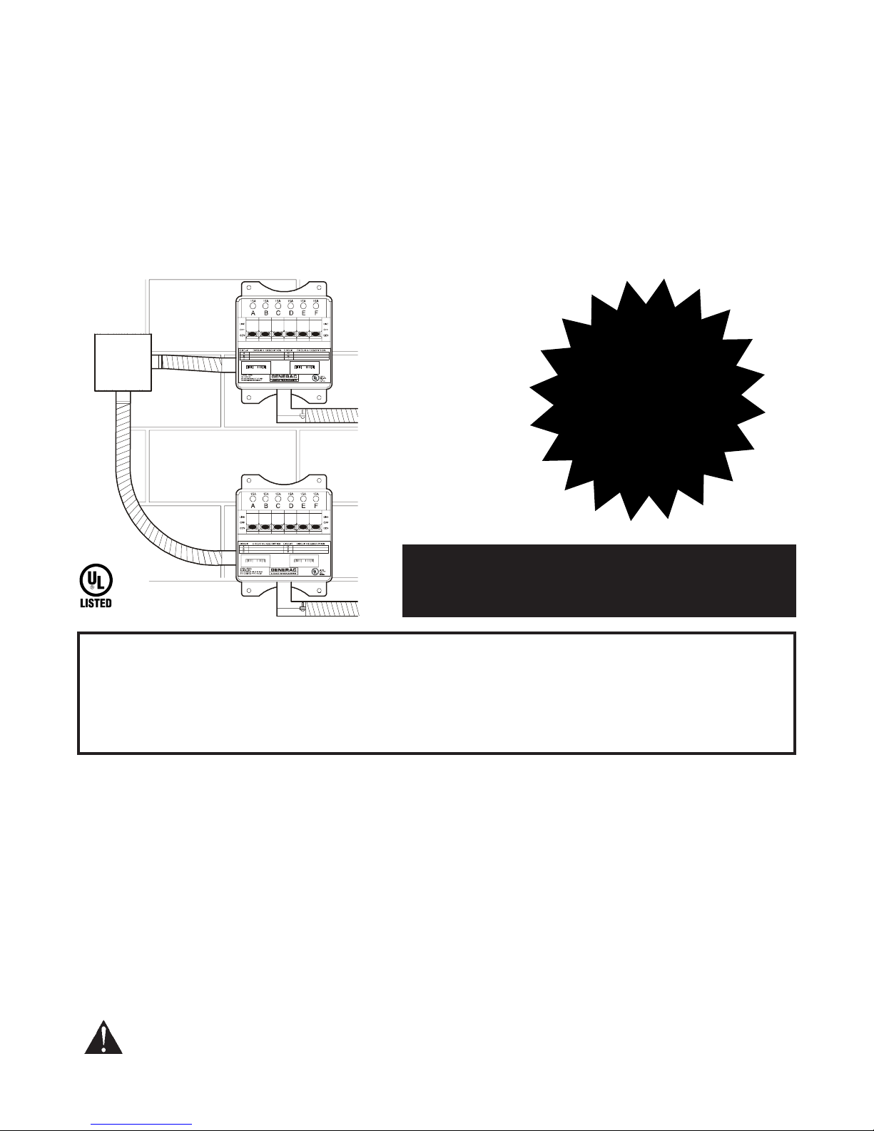
The Model 1403 Power Transfer System safely connects up to twelve essential household loads, such as the
furnace fan, freezer, refrigerator, water well pump, sump pump, lighting or outlet circuits to either the utility power
or a portable generator. In the event of a utility power failure, the homeowner can safely select devices to be
powered by an outdoor portable generator. Self-contained load meters assist the operator when managing power
loads. The power transfer system will not permit connection to both utility and generator power at the same time.
The Model 1403 Power Transfer System is easy for a licensed electrician or qualified professional to install, safe
for a homeowner to operate, and will work with 240 Volt AC generators factory equipped with a NEMA type
14-50R receptacle.
This manual contains important warnings and information. READ AND RETAIN FOR REFERENCE.
IMPORTANT
This product must be installed in compliance with local residential wiring and electrical codes by a
licensed electrician or qualified professional. Generac Portable Products is not responsible for
damaged equipment, accidents, or personal injury caused by incorrect installation.
Read this Safety Manual and Instructions BEFORE operating Power Transfer System.
CONTENTS:
Installation Instructions - - - - - - - - - - - -Page 1 through 12
Owners Operating Procedure - - - - - -Page 13 through 16
Page 2
Generac Portable Products Power Transfer System
2
NOTE: The maximum load allowed through each
Load Manager switch is 7200 Watts: 30 Amps at
240 Volts or 60 Amps at 120 Volts.
Per National Electric Code, connection of a
generator to any electrical circuit normally
powered by an electric utility must be by means
of approved transfer switch equipment so as to
isolate the electrical circuit from the utility
distribution system when the generator is
operating. Failure to isolate the electrical circuits
by such means may result in injury or death to
utility power workers due to backfeed of
electrical energy.
CAUTION: Each Load Manager switch is for
indoor use only. The connection box is a NEMA
type 3R, intended for outdoor use.
NEMA stands for National Electrical Manufacturers Association.
GENERATOR
COMPATIBILITY
Only use a generator that is
factory-equipped with a NEMA
Type 14-50R receptacle.
NEVER use a generator equipped
with a 3-prong 240 Volt receptacle
because damage may occur in
connected appliances.
CARTON CONTENTS
Items in the shipping carton include:
Two Load Manager Switches
Connecting Box
Connecting Cord Set
50 Amp Connecting Plug
Attention Decal
If any of the above parts are missing or damaged, call
the Generac helpline at 18002701408.
UNPACKING
Remove the Power Transfer System components from
the shipping carton. Each Load Manager switch is
completely prewired and ready for installation. Inspect
the switches and attached wires and flexible conduit
for any shipping damage.
The connection box is supplied ready to be wired.
Inspect the box, the connection cord set, and the
connecting plug for any damage.
The installer will select and attach the connecting cord
plug, as described in the Installation Procedure,
step 22.
Items Not Shipped with Power Transfer System:
The following items, required for system installation,
are not included and must be provided by the installer:
1. Tools required for installation
2. Anchors and screws to mount the power transfer
system components and conduit.
3. Junction box(s), conduit, fittings, wire nuts, and
insulated copper wire for connecting the Load
Manager switches to the outside connection box.
SPECIFICATIONS
Model Number.......................................................1403
Maximum Circuits......................................................12
Maximum Load/Circuit from Generator ...........15 Amps
Maximum Load/Circuit from Load Center .......20 Amps
Maximum Watts per Load Manager...................7200
Connecting Cord Length .........................................8 ft.
Page 3

Generac Portable Products Power Transfer System
3
GENERAL SAFETY
INFORMATION
1. A licensed electrician or qualified professional
(referred to herein as installer) must install
the power transfer system per local code.
2. During installation, the installer is required to
remove the cover from the building power
distribution panel (referred to herein as a load
center.) To reduce the risk of electrical shock, the
Main circuit breaker must be turned OFF while the
load center cover is removed.
3. DO NOT OVERLOAD THE GENERATOR.
Overloading a generator in excess of its rated
wattage capacity will trip generator circuit
breakers.
4. Always plug the connecting cord set into the
connection box and generator BEFORE starting
the generator. Always shut the generator down
before detaching the cord set.
5. Portable generators attached to this Power
Transfer System must be operated outside, in
accordance with warnings and instructions found in
the generators Owners Manual.
PLAN THE INSTALLATION
The installer and the homeowner decide which circuits
are to be powered by the generator during a utility
power outage:
The plan should ensure that no single circuit load
exceeds 15 Amps.
The plan should also identify circuits that exceed the
15 Amp maximum.
During generator operation, the homeowner should
use only necessary household items and to alternate
use of larger loads, such as water pump or electric
skillet. The installer will instruct the homeowner in
appropriate load management techniques.
Three methods of determining loads are given here:
Measure Actual Loads
The installer uses a clamp-on ammeter to measure
each of the actual desired loads to ensure each total
circuit draws less than 15 Amps.
Sum Loads from Data Plates
The installer inspects each desired device, notes
current consumption found on labels on each
appliance, then adds all loads on each circuit:
The rated current of appliances and motors can
usually be found on a data plate or decal affixed to
the device.
The rated wattage of lights can be taken from light
bulbs.
Some electric motors, such as induction types,
require about three times more power for starting
than for running. This surge of power lasts for only a
few seconds when starting such motors. Be sure to
allow for this high starting load.
Estimate Loads
The third method estimates total circuit loads based on
information given in Figure 1.
APPLIANCE ~ ~ ~ ~ ~ ~ ~ ~ ~ ~ ~ ~ ~ ~ ~ ~LOAD DRAW
Air Conditioner (12,000 BTU) ~ ~ ~ ~ ~(1700W) 7A@240V
Coffee Maker ~ ~ ~ ~ ~ ~ ~ ~ ~ ~ ~ ~(1000W) 8.4A@120V
*Electric Range (one element) ~ ~ ~(1500W) 6.3A@240V
Electric Blanket ~ ~ ~ ~ ~ ~ ~ ~ ~ ~(1500W) 12.5A@120V
Electric Skillet ~ ~ ~ ~ ~ ~ ~ ~ ~ ~ ~(1250W) 10.5A@120V
*Freezer ~ ~ ~ ~ ~ ~ ~ ~ ~ ~ ~ ~ ~ ~ ~(500W) 4.2A@120V
*Furnace Fan (1/3 HP) ~ ~ ~ ~ ~ ~ ~(1200W) 10A@120V
*Jet Pump ~ ~ ~ ~ ~ ~ ~ ~ ~ ~ ~ ~ ~ ~(800W) 3.4A@240V
Light Bulb ~ ~ ~ ~ ~ ~ ~ ~ ~ ~ ~ ~ ~ ~(100W) 0.9A@120V
Microwave Oven ~ ~ ~ ~ ~ ~ ~ ~ ~ ~ ~(700W) 5.9A@120V
Oil Burner on Furnace ~ ~ ~ ~ ~ ~ ~ ~(300W) 2.5A@120V
Oil Fired Heater (30,000 BTU) ~ ~ ~ ~(150W) 1.3A@120V
Oil Fired Heater (85,000 BTU) ~ ~ ~ ~(225W) 1.9A@120V
Oil Fired Heater (140,000 BTU) ~ ~ ~(400W) 3.4A@120V
Radio ~ ~ ~ ~ ~ ~ ~ ~ ~ ~(50 to 200W) 0.5 to 1.7A@120V
*Refrigerator ~ ~ ~ ~ ~ ~ ~ ~ ~ ~ ~ ~ ~ ~(600W) 5A@120V
*Submersible Well Pump (1 HP) ~ ~(2000W) 8.4A@240V
Sump Pump ~ ~ ~ ~ ~ ~ ~ ~ ~ ~ ~ ~ ~ ~(600W) 5A@120V
Television ~ ~ ~ ~ ~ ~ ~ ~(200 to 500W) 1.7 to 4.2A@120V
* Allow 3 times the listed watts for starting these devices.
WATTS = AMPS x VOLTS
Figure 1 Load Reference Guide
Page 4
Generac Portable Products Power Transfer System
4
INSTALLATION
PROCEDURE
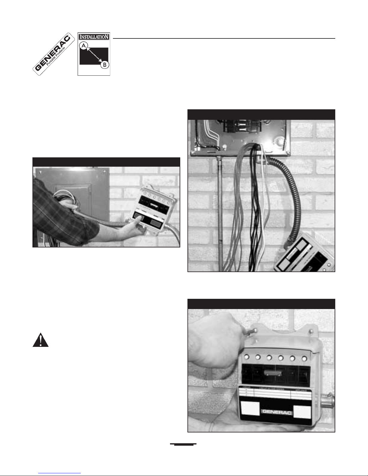
Load Manager Switch
Before removing the load center cover, plan mounting
location for both Load Manager switches. To do so,
hold a Load Manager switch about 18 inches from
the center of the load center, as shown in Figure 2.
NOTE: The following procedure describes the
installation of one Load Manager switch. Use
identical instructions to install and test the second
Load Manager switch.
1. Ensure there is enough room to mount both Load
Manager switches so their flex conduit attaches
directly to the load center.
2. Identify appropriate vacant load center 3/4
knockouts.
DANGER: Contact with wires and terminals
inside the load center must be avoided as
contact may result in dangerous electrical
shock. Before removing the load center cover,
switch OFF the main circuit breaker serving the
load center. Remember that wires on the line
side of the main circuit breaker are electrically
dangerous.
3. Turn OFF the load centers main circuit breaker,
then remove the load center cover.
4. Remove the predetermined knockouts. Route all
wires extending from the flexible conduit attached
to a Load Manager switch through the empty
hole, as shown in Figure 3. Secure the conduit
connector to the load center with the supplied lock
nut.
5. Anchor the Load Manager switch to the wall at
the selected position, as shown in Figure 4.
Figure 2 Planning Switch Location
Figure 3 Wire Loom from Switch
Figure 4 Anchoring Load Manager Switch
Page 5
Generac Portable Products Power Transfer System
5
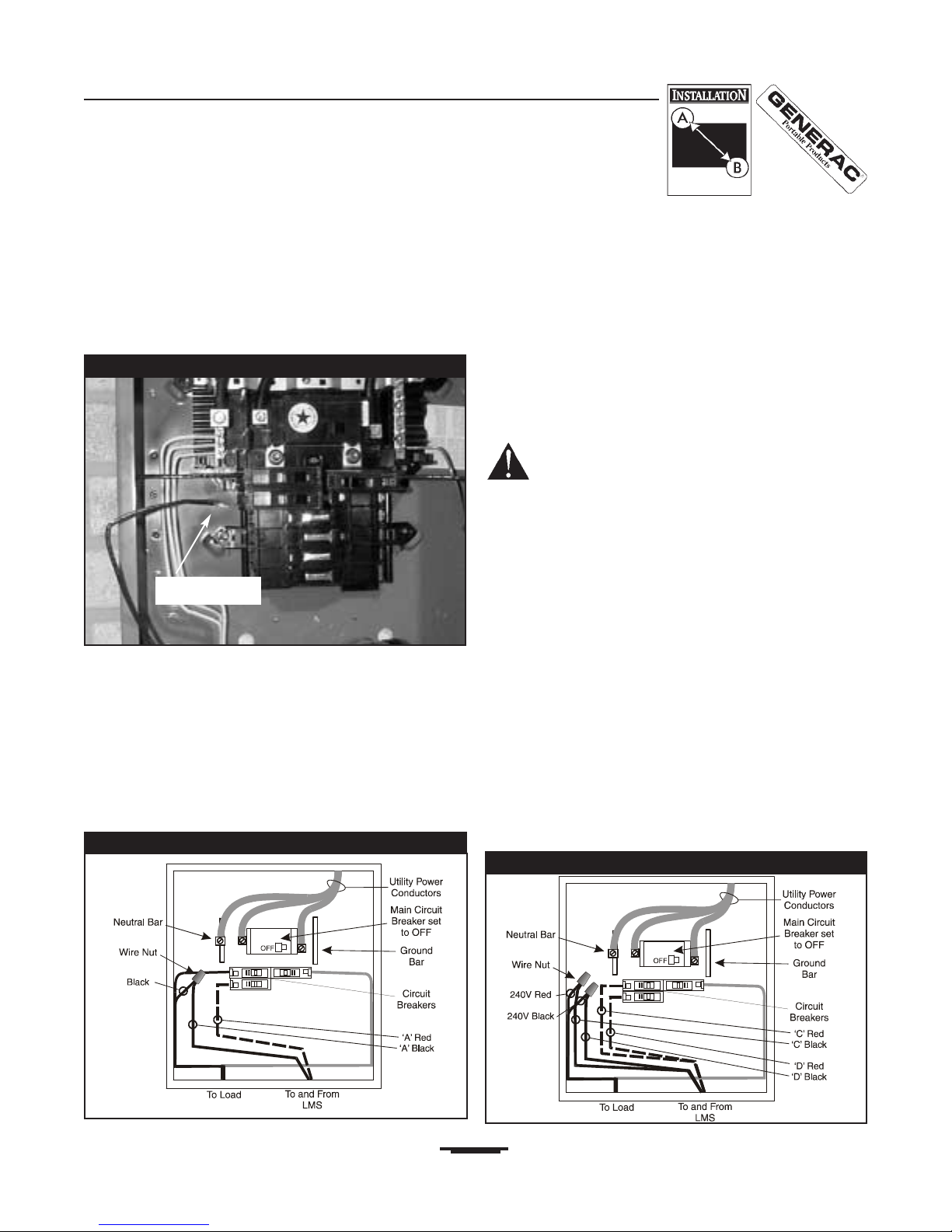
6. From the load management plan, determine the
load that is to be connected to Load Manager
switch circuit A. Turn that load center circuit
breaker to its OFF position. Loosen the screw
that retains the wire to this breaker, then detach
the wire. Figure 5 shows the selected load wire
detached from the circuit breaker.
7. Find the black and red wires marked A that come
from the Load Manager switch. Using good
workmanship, route both of these wires near the
selected circuit breaker. Trim and strip the red A
wire and install it properly into the circuit breaker.
8. Trim and strip the black A wire to mate with the
wire previously detached from the breaker. Secure
the wire ends with a wire nut. Neatly dress the
wires into the load center, as shown in Figure 6.
IMPORTANT:The installer should never cross the
black and red leads from the Load Manager switch.
Doing so will void the warranty and could cause
significant damage to Load Manager components
and the generator.
Make Sure:
The RED wire from the Load Manager switch is
always connected to the circuit breaker.
The BLACK wire from the Load Manager switch is
always connected to the wire going to the load.
DANGER! You must connect the Load
Manager switch wires as described or serious
damage to the equipment or yourself may result.
9. Select the load center circuit that will become load
management circuit B. Repeat Steps 6 through 8
for the red and black wires marked B coming
from the Load Manager switch.
10. If you wish to connect a 240 Volt AC two-pole
circuit, such as a well pump, proceed as follows:
a. Turn off the two-pole circuit breaker used for
the pump circuit and detach the load wires
from that breaker.
b. Select the four wires marked C and D
coming from the Load Manager switch
conduit and route them close to the selected
circuit breaker(s).
c. Repeat Steps 6 through 8 for each pair of red
and black wires C and D.
d. A typical two-pole circuit connection is shown
in simplified form in Figure 7.
Figure 7 Two-pole Connection
Figure 5 Wire Detached From Breaker
Wire removed
Figure 6 Single-pole Connection
Page 6

Generac Portable Products Power Transfer System
6
11. If a two-pole circuit is not needed, the two-pole
coupled switch can be converted into two singlepole circuits. Simply remove and discard the
handle tie connecting load management circuits
C and D, as shown on the right in Figure 8.
12. When steps 6 through 8 have been completed for
all desired circuits, install the WHITE (neutral) lead
coming from the Load Manager switch, as
follows:
a. Find an unused hole in the load center neutral
bar.
b. Trim and strip the white wire and install it into
the neutral bar.
c. Figure 9 shows a properly-connected WHITE
lead.
13. Install the GREEN lead coming from the Load
Manager switch, as follows:
a. Find an unused hole in the load center
GROUND bar.
b. Trim and strip the green wire and install it into
the GROUND bar.
c. Remove protective backing from the Attention
Decal. Per National Electric Code, affix decal
to load center surface closest to the green wire
installed in (b.) above.
d. If no ground bar exists, install the GREEN wire
into an unused hole in the neutral bar. Affix
label as described in (c.).
e. Figure 10 shows a properly-connected GREEN
lead.
14. Install the second Load Manager switch,
repeating the instructions given in Steps 4 through
13 above.
15. After both Load Manager switches have been
installed, install the load center cover. Set all
switches on both Load Manager switches to the
LINE position. Turn ON the load center MAIN
breaker. All breakers in the load center connected
to Load Manager circuits should be switched on.
Load Manager switch installation is now
complete.
Figure 10 GREEN Lead Installation
Figure 9 WHITE Lead Installation
(Neutral)
Figure 8 Convert Two Pole to Single Pole
Handle Tie Installed Handle Tie Removed
Page 7

Generac Portable Products Power Transfer System
7
Connection Box
The installer should use local codes and the following
procedure to install the generator connection box
provided with this system.
16. Locate and mount the connection box on an
outside wall as close as possible to the load
center. However, consider household air intake
ducting when when locating generator and
connection box. A typical power transfer system
complete installation is depicted in Figure 11.
17. As shown in Figure 12, mount a junction box at the
appropriate distance from the Load Manager
switches so that both 1/2 flexible conduits can be
connected to it.
Figure 12 Junction Box Installation
Figure 11 Typical Completed Power Transfer System Installation
Page 8

Generac Portable Products Power Transfer System
8
18. Referring to Figure 13, remove the connection box
inner panel. Mount the connection box at its
planned location on an outside wall.
19. Run appropriately sized conduit from the junction
box to the connection box. Anchor all boxes,
conduit, and fittings.
20. Pull four properly-sized insulated wires through the
conduit joining the junction box and the connection
box. Trim and strip each wire in the junction box.
Make secure connections using wire nuts.
Figure 14 shows wires from one of the two Load
Manager switches installed. When both switches
have been connected, install the junction box
cover.
Figure 13 Connection Box Installation
Figure 14 Junction Box Connections
Page 9

Generac Portable Products Power Transfer System
9
21. As shown in Figure 15, trim, strip, and connect
each wire to the appropriate terminal on the
locking receptacle on the connection box inner
panel. Use the schematic affixed to the inside of
the connection box to make proper wire
connections. When all connections have been
made, install the connection box inner panel.
Connecting Cord Set
22. Referring to the schematic in Figure 16 and the
markings on the connector itself, properly attach
the plug to the pigtail end of the connecting cord
set.
Identifying Circuits
A label, similar to that depicted in Figure 17, is
provided on each Load Manager switch cover. The
installer should fill in this information, describing the
appliance and the related circuit numbers in the load
control center.
This completes the installation of the Generac Portable
Products Power Transfer System. The installer should
test the system, as described in the TESTING section,
and instruct the homeowner in proper routine testing
techniques.
Figure 15 Connection Box Connections
Figure 16 50 Amp Cord Set Connector
Figure 17 Circuit Identification Label
Page 10

Generac Portable Products Power Transfer System
10
INSTALLATION AND LOAD MANAGEMENT NOTES
Page 11

Generac Portable Products Power Transfer System
11
LOAD MANAGER SCHEMATIC DIAGRAM
Page 12

Generac Portable Products Power Transfer System
12
Item Part No. Qty. Description
1 20030 1 COMPLETE ENCLOSURE,
Front & Back
2 39271 1 CONNECTOR, 90 Degree
3 98927 1 ASSY., Switch, 3 Position
Item Part No. Qty. Description
4 99151 1 ASSY., Circuit Breaker, 15
Amp
5 B4603 2 METER, 30 Amp, 3600 Watt
6 B5683 2 BUSHING, Anti Short
Item Part No. Qty. Description
1 B4608 1 CORD SET, Connecting
2 97774 2 SWITCH, Load Manager
3 B4609 1 BOX, Connecting
Item Part No. Qty. Description
4 B4626 1 DECAL, Attention
5 B4612 1 PLUG, Connecting
EXPLODED VIEW & PARTS LIST
Page 13

Generac Portable Products Power Transfer System
13
OPERATING PROCEDURE
This manual section describes the routine procedures
used by the owner to operate the Power Transfer
system.
Each Load Manager switch is equipped with six
three-position switches. The switch positions labeled
LINE are used for connecting the desired devices to
the utility power source. The switch positions labeled
OFF are used for load management. The switch
positions labeled GEN are used for connecting
desired circuits to the generator power source.
Switch To Generator Power
To switch to generator power after a utility power
failure:
1. Ensure all Load Manager switches are in LINE
position, as shown in Figure 18.
2. Align the female socket of the connecting cord set
with the connection box receptacles mating male
prongs, as shown in Figure 19. Push cord set
connector in and twist clockwise to lock.
3. Align the male prongs on the other end of the cord
set with the mating female terminals of the
generators 50 Amp 240V receptacle, as shown in
Figure 20. Push connector fully into receptacle.
4. Ensure generator is outdoors and fuel is adequate.
5. Start the generator using instructions given in the
generator owners manual.
Figure 18 Switches in LINE Position
Figure 19 Connection Box Connection
Figure 20 Align Connector at Generator
Page 14

Generac Portable Products Power Transfer System
14
6. At the Load Manager switches, move desired
circuit switches from LINE position to GEN
position (as shown in Figure 21).
Load Management
The number of circuits that can be operated
simultaneously during a utility failure will depend on the
wattage capacity of your generator. Most portable
generators do not have the capacity to handle loads on
all Load Manager switch circuits at the same time.
Review the load management plan developed with the
installer (see Plan the Installation). It may be
necessary to selectively turn on and off certain loads
while using generator power so that necessary
appliances can be operated safely.
The watt meters provided on the Load Manager
monitor the current draw through each set of three
circuits (i.e.: circuits A, B, and C are monitored by
the lower left meter; circuits D, E, and F are
monitored by the lower right meter.) When switching
loads to the GEN position, watch the watt meter to
ensure that maximum current levels are not exceeded.
Switch To Utility Power
To revert from generator power to utility power after
utility power is restored:
1. At the Load Manager switches, place all
switches in LINE position, as shown in Figure 18.
2. Shut off the generator.
3. Disconnect the connecting cord set from the
generator and the connection box.
Testing
Following installation and periodically thereafter, test
the power transfer system as follows:
1. Ensure that all Load Manager switches are at
LINE position (see Figure 18).
2. Connect the connection cord set to the house
connector box (see Figure 19).
3. Connect the other end of the connection cord set
to the generator (see Figure 20).
4. Start the generator.
5. At one of the Load Manager switches, set the
A switch to the GEN position, as shown in
Figure 22. Verify that the load attached to the A
circuit is operating properly. Return A switch to
LINE position.
6. Repeat Step 5, above, for each remaining load
management circuit on both switches.
Circuit Breakers in Load Manager
Switch
Individual Load Manager switch circuits A through
F are each protected by a 15 Amp circuit breaker.
These breakers are labeled A, B, C, and so forth,
as seen in Figure 22, for example. If an electrical load
on one of these circuits exceeds 15 Amps, the Load
Manager switch circuit breaker will open.
To reset a Load Manager switch breaker:
1, Eliminate the overload condition.
2. Place the switch with the tripped circuit breaker in
the OFF or middle position.
3. Press in the circuit breaker button and observe that
the button remains in.
4. Place the switch that was in the OFF position back
to GEN (or LINE, if that is what is desired).
The load controlled by that Load Manager switch
circuit should now be operating properly.
If the circuit breaker does not reset, contact a licensed
electrician to repair the problem.
Figure 21 All Switches in GEN Position
Figure 22 A Switch in GEN Position
Page 15

Generac Portable Products Power Transfer System
15
TROUBLESHOOTING
Problem Cause Solution
Generator is running, but no
AC output is available.
1. Generator circuit breaker is
open.
2. Poor connection or defective
cord set.
3. Connected device is bad.
4. Fault in generator.
1. Reset circuit breaker.
2. Check and repair.
3. Select a different appliance or load
that is in good condition.
4. Contact authorized service center.
Generator runs good but
bogs down when loads are
connected.
1. Short circuit in a connected
load.
2. Generator is overloaded.
1. Disconnect shorted electrical load.
2. See Load Management on page 14.
All Load Manager switches
do not work when on
generator power.
1. Load management switches
in OFF or LINE positions.
2. Generator circuit breaker is
open.
3. Poor connection or defective
cord set.
4. Connected device is bad.
5. Fault in generator.
1. Set Load Manager switches in GEN
position.
2. Reset circuit breaker.
3. Check and repair.
4. Select a different appliance or load
that is in good condition.
5. Contact authorized service center.
Appliances dont work after
utility power comes back on.
1. Load management switch in
OFF or GEN position.
2. Load management switch
circuit breaker(s) is open.
1. Set switch to LINE position.
2. Reset circuit breaker. See Circuit
Breakers in Load Manager Switch
section, page 14.
Only some loads work on
generator power.
Load management switch circuit
breaker is open.
Reset circuit breaker. See Circuit
Breakers in Load Manager Switch
section, page 14.
Wattmeter overloaded.
Connected loads on circuits
exceed 3600 watts.
Reduce loads on circuits.
Page 16

LIMITED WARRANTY
One Year Limited Warranty
Generac Portable Products (hereafter referred to as the COMPANY), warrants to the original purchaser that this
Power Transfer System will be free from defects in material and or workmanship for a period of one year from
date of original sale. To register Power Transfer System ownership, the Owners Registration card must be
completed and returned to the COMPANY by the installer (licensed electrician or qualified professional). Any
equipment that the buyer claims to be defective in material and or workmanship must be examined by a licensed
electrician or qualified professional who is familiar with local electrical codes. The COMPANY will, at its option,
repair and/or replace any part which is found by the COMPANY to be defective under normal use and service. All
transportation costs under this warranty, including return to the factory, are to be borne and prepaid by the
purchaser.
Warranty Schedule
Year One - 100% for all components (as listed in manual)
All warranty expense allowances are subject to the conditions as defined in the published COMPANY Policies
and Procedures Manual.
This Warranty Shall Not Apply To:
1. Power Transfer Systems NOT installed by a licensed electrician or qualified professional.
2. Cost of installation or start-up.
3. Travel expenses of individuals performing repairs.
4. Units used as demonstrators or rentals.
5. Failures due to (a) normal wear and tear, or (b) accident, misuse, abuse, negligence, or improper installation.
Incidental, consequential, or indirect damages caused by defects in material or workmanship, or any costs
associated with the delay in repair or replacement of the defective parts.
THIS WARRANTY REPLACES ALL PREVIOUS POWER TRANSFER SYSTEM WARRANTIES,
EXPRESS OR IMPLIED. SPECIFICALLY, THE COMPANY MAKES NO OTHER WARRANTIES AS TO
MERCHANTABILITY OR FITNESS FOR A PARTICULAR PURPOSE. THE COMPANYS ONLY
LIABILITY SHALL BE THE REPAIR AND/OR REPLACEMENT OF PARTS AS STATED ABOVE. IN NO
EVENT SHALL THE COMPANY BE LIABLE FOR ANY INCIDENTAL OR CONSEQUENTIAL
DAMAGES.
Generac Portable Products
Jefferson, Wisconsin U.S. A.
 Loading...