

Page 1
Surface Mount Models: Flush Mount Models:
004996-0 004997-0 Standard Annunciator
004998-0 004999-0 Annunciator w/Remote Relay Panel
PM-DCP 20-light
Remote Annunciator
Owner’s Manual
GEN.
RUN.
PRESSURE
GENERAC
LOW
OIL
BATTERY
CHARGER
FAILURE
PRE - ALARMS
HIGH
WATER
TEMP.
LOW
BATTERY
VOLTAGE
LOW
WATER
TEMP.
HIGH
BATTERY
VOLTAGE
LOW
FUEL
®
POWER SYSTEMS
1 AMP
RPM
SENSOR
LOSS
LOW
OIL
PRESSURE
RESET
ALARM
OVER
CRANK
HIGH
WATER TEMP
LOW WATER
LEVEL
RE-ARM
HORN
OVER
SPEED
EMERGENCY
STOP
GEN.
POWER
NOT
IN
AUTO
POWER MONITOR
TEST
ON
OFF
SYSTEM
READY
LINE
POWER
REMOTE START
COMMS.
OK
0A6733
ON
OFF
Page 2

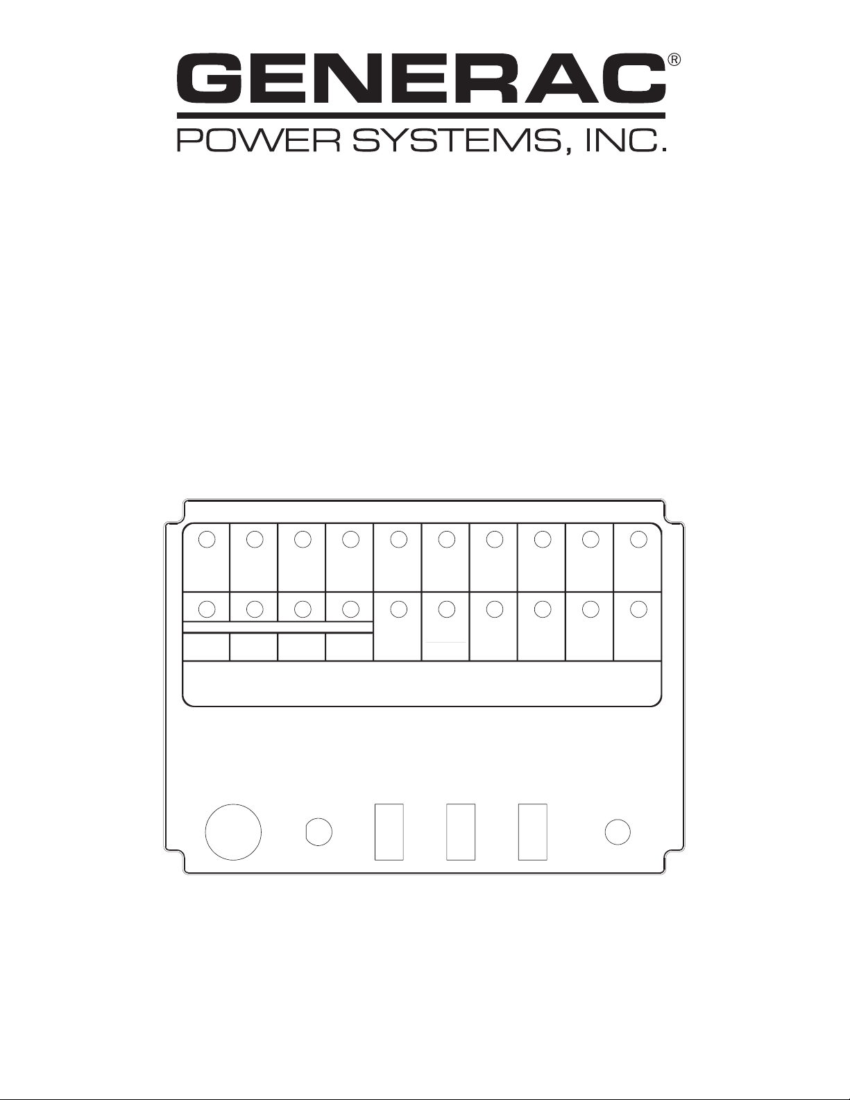
20-light Remote Annunciator
DETAILED SPECIFICATIONS
ENVIRONMENTAL SPECIFICATIONS
Temperature -20°C to +50°C
Humidity 0 to 95% Non Condensing
POWER SUPPLY REQUIREMENTS
Power Supply Source Generator Battery to comply
with NFPA
Nominal Supply +12 to +24VDC
Transient protection Spikes clamped to 40V
Power Usage 150mA maximum.
Battery Supply cable 2 wire - DC resistance less
than 7 Ohms per conductor.
Fuse on front panel 1 Amp
COMMUNICATION WITH GENERATOR CONTROL
SYSTEM
Communication link 2 wire RS485 fully isolated.
Communication cable 2 wire—twisted pair with
overall screen.
Cable size 24 AWG 0-250 feet. 18 AWG
0-1,200 feet.
Baud rate 4800, N, 8, 2.
NOTE:
1. The RS485 cable should not be run in the same
conduit, or in the same grouping as any high voltage or other “noisy” electrical conductors.
2. Avoid running the RS485 cable through any “high
noise” environments.
INTERFACE WITH OTHER EQUIPMENT
Alarm Relay Output 1 pair N/O Volt-free contacts-
100mA, 24V DC
AGENCY COMPLIANCE
NFPA-110 Yes
NFPA-99 Yes
TRANSPORTATION AND STORAGE
Temperature -20°C to +80°C
Humidity 0-95% Non Condensing
Detailed Specifications ..................................................2
Environmental Specifications ........................................2
Power Supply Requirements..........................................2
Communication With Generator Control System ..........2
Interface With Other Equipment ....................................2
Agency Compliance ......................................................2
Transportation and Storage ..........................................2
Packaging and Mounting................................................3
Annunciator Panel Mounting..........................................3
System Specification ......................................................3
Active/Passive Mode ......................................................3
Setting to Passive Mode ................................................4
Hardware Functional Description ..................................4
Generator Stop Signals..................................................4
Warning Indicators ........................................................4
Generator Power............................................................5
Line Power ....................................................................5
Battery Charger AC Failure............................................5
System Status Indicators ..............................................5
System Ready................................................................5
Communication OK........................................................6
Audible Annunciator ......................................................6
Test Switch ....................................................................6
Re-Arm Horn Switch ......................................................6
Reset Switch ..................................................................6
Relay Output ..................................................................6
Software Specification....................................................6
Serial Interface ..............................................................6
Request Frequency........................................................6
Operator Functions ........................................................6
Error Handling................................................................6
Hardware Watchdog ......................................................6
Troubleshooting ..............................................................7
Notes ................................................................................8
Electrical Data ................................................................9
Exploded Views & Parts Lists......................................12
2 Generac®Power Systems, Inc.
Page 3
20-light Remote Annunciator
Generac®Power Systems, Inc. 3
PACKAGING AND MOUNTING
Enclosure type Sheet metal box.
Base panel Generac part #0A6985/0A7437
Front panel Generac part #0A6988/0A7443
Panel overlay Generac part #0A6733
Mounting Flush or Wall.
Weight requirements None
Manuals Yes - Operator guide
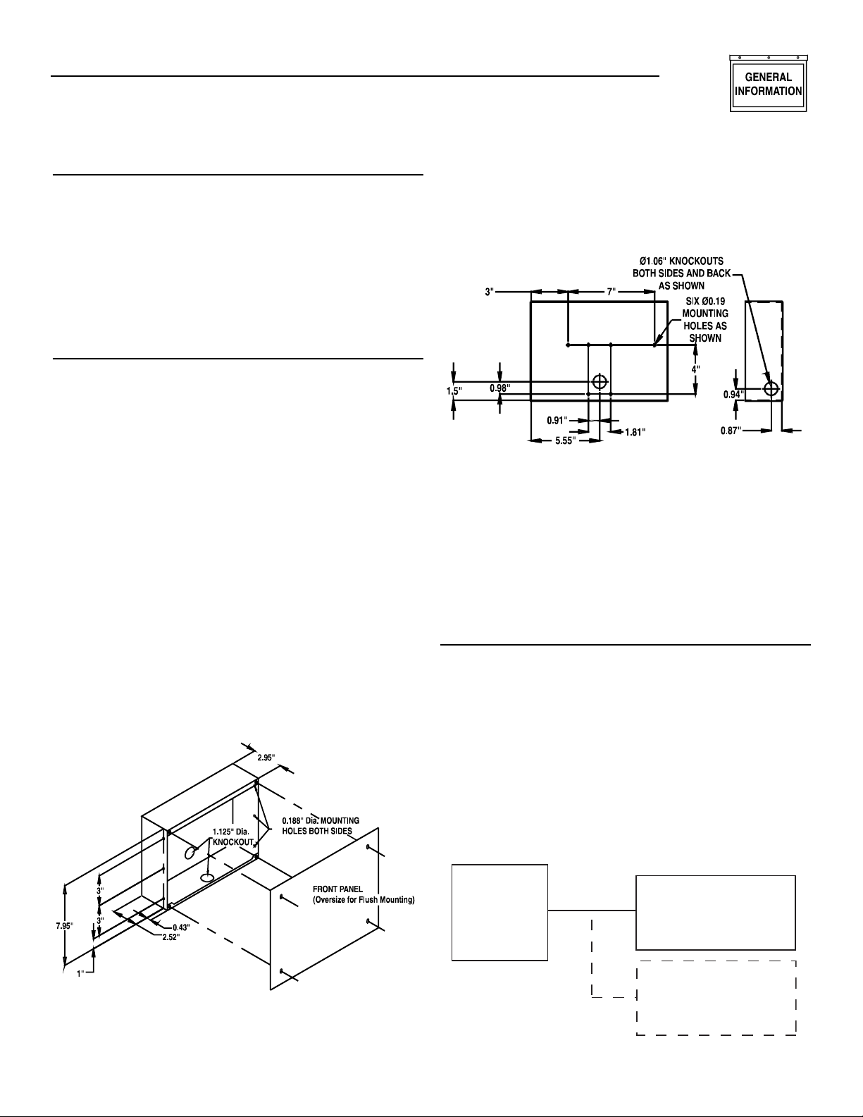
ANNUNCIATOR PANEL MOUNTING
NOTE:
For ALL models installation must always comply
with applicable codes, standards, laws and regulations. Adhere strictly to local, state and national
electrical and building codes. Comply with regulations the Occupational Safety and Health
Administration (OSHA) has established. Also, the
generator and related components must be installed
completely in conformance with the manufacturer’s
instructions and recommendations. Following proper
installation, do nothing that might alter a safe installation and render the unit in non-compliance with
such codes, standards, laws and regulations.
The Remote Annunciator panels (Models 004997-0 and
004999-0) are intended for flush mounting. Panel
mounting dimensions are shown in the illustration
below. The panel can be installed behind a cutout in an
existing sheet metal panel by using the four mounting
holes in its front panel. For wall mounting, use a square
outlet box behind the annunciator panel.
Flush Mounting Dimensions
The Remote Annunciator panels (Models 004996-0, and
004998-0) are mounted using any combination of the
mounting holes in the back panel of the box itself.
Surface Mount Dimensions
SYSTEM SPECIFICATION
The 20-light remote annunciator panel (RAP) directly
interacts with Generac’s control systems, and provides
remote monitoring and annunciation of 17 generator
parameters, two system-level warnings - System Ready
and Communications OK, and one spare channel.
Power to the RAP is supplied from the generator battery
(+12VDC to +24VDC) via a 2-wire link.
ACTIVE/PASSIVE MODE
The 20-light remote annunciator can be set to operate in
either ACTIVE or PASSIVE mode. In ACTIVE mode, it is
a modbus master and will request data from the DCP.
The DCP must be set as a slave port. In PASSIVE mode,
it is a modbus slave and must be connected to a master
port on the DCP; or, it can be hooked onto a masterslave link as a pure listening device. This method allows
for the connection of more than one annunciator.
An annunciator connected to an engine controller would
be a master.
Annunciator Connected to Engine Controller
PM-GC
(Slave)
Annunciator
(Master)
Slave
Page 4
4 Generac®Power Systems, Inc.
An annunciator connected to a system controller would
be a slave.
Annunciator Connected to System Controller
DO NOT set the PM-GC to a modbus master port.
This connection will not work.
SETTING TO PASSIVE MODE
To set the 20-light annunciator to passive mode, simply
connect an 18 to 22 gauge wire between header positions J3-1 and J3-2.
NOTE:
1. It is not recommended to connect more than a
total of two 20-light remote annunciator panels.
(one set to active mode, one set to passive mode)
2. Up to four remote relay panels can be used with
the two 20-light remote annunciators.
HARDWARE FUNCTIONAL DESCRIPTION
The Remote Annunciator Panel communicates with the
control system and updates the light panel and audible
annunciator as described below.
GENERATOR STOP SIGNALS
These lights will flash when any alarm occurs and the
horn will sound as follows:
The ‘Re-Arm Horn' switch can be used to turn off and
re-arm the horn, or the alarms can be fully acknowledged using the ‘Reset' switch.
The ‘Reset' switch will turn off and re-arm the horn, and
any flashing lights will switch to the ON state until the
alarms are no longer present at the generator control
panel.
NOTE:
1. Alarm condition MUST be reset at the generator
set control panel.
2. When this annunciator is used in a Modular Power
System (MPS), an alarm on any one of the generators will cause the above lights to light, and alarm
to sound.
WARNING INDICATORS
These lights will flash when any alarm occurs and the
horn will sound according to the following table:
These alarms will be latched/not latched by the RAP
according to the above table. They can be acknowledged
at the RAP using the ‘Reset' switch—the active lamps
will then stop flashing and remain in the ON state until
the alarm signal clears from the generator control
panel. The ‘Reset' switch will also turn off and re-arm
the horn.
NOTE:
1. These lamps can only be fully reset when the
alarm state is no longer active and “Reset” has
been pressed at both the generator control panel
and the RAP.
Alternatively, at any time the horn can be turned
OFF and re-armed with the ‘Re-Arm Horn’ switch.
2. When this annunciator is used in a Modular Power
System (MPS), a warning on any one of the generators will cause the above lights to light, and
alarm to sound (if the warning is audible).
!
20-light Remote Annunciator
Annunciator Light Light Audible
Color Alarm
RPM Sensor Loss Red Yes
Overcrank Red Yes
Overspeed Red Yes
Low Oil Pressure Red Yes
High Water Temp/Low Water Level Red Yes
Emergency Stop Red Yes
Annunciator Light Light Audible Latched
Color Alarm
Pre-low OIl Pressure Yellow Yes Yes
Pre-high Water Temp Yellow Yes Yes
Pre-low Water Temp Yellow Yes Yes
Pre-low Fuel Yellow Yes Yes
Battery Charger AC Failure Yellow Yes No
Low Battery Voltage Yellow Yes No
High Battery Voltage Yellow No No
Generator Run Yellow No No
Generator Power Yellow No No
Not in Auto Red Yes No
PM-SC
(Master)
Annunciator
(Slave)
Slave
DANGER
Page 5

Generac®Power Systems, Inc. 5
20-light Remote Annunciator
GENERATOR POWER
This light indicates different things depending on the
type of system it is attached to.
• For a PowerManager System Controller (PM-SC with
external transfer switch(es)), generator power is
defined as any one or more generators in the system
running and connected to the generator bus.
• For a PowerManager Integrated Controller (PM-IC
with integrated transfer switch), it represents the status of the generator’s side auxiliary contact of the
internal transfer switch. This shows whether the load
is powered by the generator.
• For a non-paralleling engine controller (PM-GC
WITHOUT internal transfer switch), it represents the
status of the input 4 (TB2-5) to the generator DCP.
This should be connected to the generator side auxiliary contact of the external transfer switch. A closure
to ground will cause the light to illuminate. This
shows whether the load is powered by the generator.
• For an engine controller that is part of an MPS system
(PM-PC), generator power represents the state of the
internal contactor that the generator is connected to.
• For a Utility paralleling engine controller (PM-GCF),
generator power represents the status of the generator side auxiliary contact of the internal transfer
switch. This shows whether the load is powered by
the generator.
LINE POWER
This light indicates different things depending on the
type of system it is attached to.
• For a PowerManager System Controller (PM-SC with
external transfer switch(es)), line power represents
the auxiliary input C (TB6-4).
• For a PowerManager Integrated Controller (PM-IC
with integrated transfer switch), it represents the status of the utility side auxiliary contact of the internal
transfer switch. This shows whether the load is powered by the utility.
• For a non-paralleling engine controller (PM-GC
WITHOUT internal transfer switch), it represents the
status of the input 3 (TB2-4) to the generator DCP.
This should be connected to the utility side auxiliary
contact of the external transfer switch. A closure to
ground will cause the light to turn ON. This shows
whether the load is power by the utility.
• For an engine controller that is part of an MPS system
(PM-PC), line power is not used.
• For a Utility paralleling engine controller (PM-GCF), it
represents the status of the utility side auxiliary contact of the internal transfer switch. This shows
whether the load is powered by the utility.
BATTERY CHARGER AC FAILURE
This light annunciates upon loss of 120 VAC power supply to the battery charger. This requires an AC relay
with normally closed contacts connected in the circuit
feeding power to the battery charger.
NOTE:
To prevent false alarms caused by brief power outages or load switching, a time delay AC relay
(approximately 30 second delay) is suggested.
SPARE
The spare indicator can be activated from the DCP by
using the programmable logic controller (PLC) feature.
SYSTEM STATUS INDICATORS
These lamps are for Status indication only—the normal
condition is ON.
SYSTEM READY
The System Ready is defined as ALL “in service” generators are ready to start, run, and supply power. Any
generators manually declared as “out of service” will not
affect this LED.
Upon a loss of System Ready, the annunciator will
respond as follows:
1. The System Ready LED will begin to flash.
2. The alarm will sound.
The “Re-arm Horn” switch can be used to turn off and
re-arm the horn, or the alarm can be fully acknowledged using the reset switch at which time the System
Ready LED will turn off and remain off until the System
Ready status is returned.
Annunciator Light Light Audible
Color Alarm
System Ready Green Yes
Communication OK Green Yes
Line Power Green No
Spare Green No
Page 6

6 Generac®Power Systems, Inc.
COMMUNICATION OK
This LED will be on as long as there is proper communication between the Remote Annunciator Panel and the
generator control system.
When communication failure occurs, the RAP will flash
the communication LED, and sound the horn. The rate
of flashing will be indicative of the cause of error.
1. No reply from the generator control system Frequency = one second on/one second off.
2. Consecutive data errors Frequency = 0.5 second on/two seconds off.
This alarm condition can be acknowledged at the RAP
using the “reset” switch - the horn will be turned off and
re-armed, and the communication OK light will continue to flash until proper communication returns.
AUDIBLE ANNUNCIATOR
See System Status Indicators chart for alarm occurrences.
TEST SWITCH
While the test switch is pressed, all lights will light and
the horn will sound. When released the lights will return
to their original status. During this test, communication
to the generator control system will be suspended.
RE—ARM HORN SWITCH
The re-arm horn switch will silence the horn and rearm it for new alarm occurrences.
RESET SWITCH
The reset switch is used to acknowledge any active
alarms. It will re-set any flashing light to ON (steady)
condition (or OFF for normally on lights). If the alarm
no longer exists and it has also been latched OFF at the
generator control panel (pre-alarm indicators only) the
active light will go OFF. It will also silence the horn and
re-arm it for new alarm occurrences.
NOTE:
Pre-alarm conditions MUST be reset at the generator
set control panel.
RELAY OUTPUT
The RAP will also provide a pair of Normally Open contacts which will mimic the status of the Audible alarm
(Horn). The relay output is fail-safe (i.e. DC supply failure will reset the relay to OFF, which will close the contacts).
SOFTWARE SPECIFICATION
In general terms, the RAP polls the generator control
system. The generator control system returns an ASCII
text string which represents the status of the indicator
lights on the panel display.
SERIAL INTERFACE
Default 4800,n,8,2
NOTE:
Set the DCP port to these settings.
REQUEST FREQUENCY
Once per three seconds.
OPERATOR FUNCTIONS
Switches will be scanned every 1/10 second.
ERROR HANDLING
An error will be reported by flashing the
Communication OK light—the rate of flashing will be
indicative of the cause of the error.
1. No reply from generator control system—frequency
one second on/one second off.
2. Consecutive data errors—frequency 0.5 seconds
on/two seconds off.
HARDWARE WATCHDOG
Will reset the CPU if :
a. Supply voltage at CPU drops below 4.65VDC.
b. CPU activity stops for 15 seconds.
20-light Remote Annunciator
Page 7

Generac®Power Systems, Inc. 7
20-light Remote Annunciator
TROUBLESHOOTING GUIDE
No LEDs are lit. 1. Check for proper battery supply at J1 pins 3 and 4.
• J1 pin 3 should be + Battery (12 or 24 volts).
• J1 pin 4 should be – Battery.
• Refer to the “power supply requirements” section at the
beginning of the manual for cable specifications.
2. Check the 1 Amp panel fuse, replace if necessary.
The “Communication OK” 1. Does the RS485 communications cable meet specifications.
LED is flashing at the rate: Refer to the “Communication with generator control system”
one second on/one second off section at the beginning of the manual.
2. Check that the RS485 connections are connected properly.
• RS485+ connected to J1 pin 1.
• RS485– connected to J1 pin 2.
• Shield is connected correctly. Refer to the wiring schematic for
your particular model located in this manual. Note the screen
should be connected on one end only.
3. Check for proper installation of the RS485 cable between the annunciator and the generator’s control system. Is this cable sharing a conduit
or running next to any high voltage or other “noisy” electrical lines?
4. Check that the DCP port is set to 4800, N, 8, 2.
5. Use GenLink communication diagnostics to check if data is being sent
or received via the Tx and Rx check boxes. Go to pull-down menu for
diagnostics and select “Com Ports”. Select the port the R.A. is connected to (normally port 0) and look to see if the check boxes change
state. If not, data is not being transmitted/received, check the cabling.
If data is being received, check the baud rate, etc.
The “Communication OK” 1. Does the RS485 communications cable meet specifications?
LED is flashing at the rate: Refer to the “Communication with generator control system”
0.5 seconds on/two seconds off section at the beginning of the manual.
2. Is the cable shield connected correctly? Refer to the wiring schematic
for your particular model located in this manual. Note that the
screen should be connected on one end only.
3. Check for proper installation of the RS485 cable between the annunciator and the generator’s control panel. Is this cable sharing a conduit
or running next to any high voltage or other “noisy” electrical lines?
4. Check that the DCP port is set to 4800, N, 8, 2.
5. Use GenLink communication diagnostics to check if data is being sent
or received via the Tx and Rx check boxes. Go to pull-down menu for
diagnostics and select “Com Ports”. Select the port the R.A. is connected to (normally port 0) and look to see if the check boxes change
state. If not, data is not being transmitted/received, check the cabling.
If data is being received, check the baud rate, etc.
Page 8

8 Generac®Power Systems, Inc.
20-light Remote Annunciator
Page 9

Generac®Power Systems, Inc. 9
(CONNECT SCREEN AT ONE END ONLY)
(
O
N
M
M
/
V
E
O
U
C
O
O
0V
N
S
-
5+
ST
P
/
O
S
S
G
O
C
O
85-
85
6
5
8
S
O
+
US
P
O
-
S
T
U
P
0
S
O
C
SC
0
S
9
S
S
ARM
O
20-light Remote Annunciator
Wiring Diagram - Drawing No. 0E5616
ARD
R B
IAT
N
TE ANN
EM
SE I/
F
E O/
F
RN +5 O/P
H
RN O/P
H
E
RE
TE
V O
RE-ARM H
R
EXTERNAL ALAR
XTERNAL ALAR
CREEN-SPAR
CREE
BATT
BATT +12
485
R
24
RS48
T
2
E
P
V
T
E
RN
-
21
2
ET
E
ET
E
2
E
2
27
2
2
P
A
.
P
RN
1
+
24 V
REEN
4
4
V
2
REEN
NLY.
R
T T
ENERAT
NNE
TEM
Y
L
NTR
T THE
END
NNE
N THI
WER
PPLY
HE
Page 10

10 Generac®Power Systems, Inc.
20-light Remote Annunciator
Wiring Diagram - Drawing No. 0E5617
Page 11

Generac®Power Systems, Inc. 11
20-light Remote Annunciator
Wiring Diagram - Drawing No. 0E5617
Page 12

ITEM PART NO. QTY. DESCRIPTION
1 0A6985 1 PANEL ANNUNCIATOR REAR
2 0A6388D 1 ASSY, 20LT MODBUS ANNUN G-PNL
4 040213 6 PCB SUPPORT SNAP-IN 1/4"
5 0A6990 1 SUPPORT, PC BOARD
6 036901 4 SCREW PPHM #6-32 X 3/8
7 0A6988 1 PANEL ANNUNCIATOR FRONT
8 0A6733 1 DECAL ANNUNCIATOR PANEL
10 061284 3 SWITCH ROCKER SPST 10@125V SPD
11 032300 1 HOLDER FUSE
12 044299 1 FUSE 1A X AGC1
13 061286 1 SOUNALERT, BUZZER
14 065511 1 PLUG PANEL PLASTIC 1/2"
16 056892 4 SCREW CRIMPTITE 10-24 X 3/8
17 025034 2 PLUG STEEL 1.0625
18 0E5620 1 HARNESS,10 WIRE REMOTE ANN
19 022985 4 WASHER FLAT #6 ZINC
20 022155 4 WASHER LOCK #6
21 022188 4 NUT HEX #6-32 STEEL
22 0F0168 1 DECAL MODEL NO. 04996-0
23 0D4462 1 DECAL,WIRING,REMOTE ANNUNCIATOR
6
0
0
0
8
J
0
0
3
3
0
3
8
6
6
5
9
0
12 Generac
®
Power Systems, Inc.
20-light Remote Annunciator
Assembly - Drawing No. 0F0169
1
1
1
2
1
21
2
1
2
1
2
1
Page 13

Generac®Power Systems, Inc. 13
ITEM PART NO. QTY. DESCRIPTION
1 0A7437 1 PANEL ANNUNCIATOR REAR
2 0A6388D 1 ASSY, 20LT MODBUS ANNUN G-PNL
4 040213 6 PCB SUPPORT SNAP-IN 1/4"
5 0A6990 1 SUPPORT, PC BOARD
6 036901 4 SCREW PPHM #6-32 X 3/8
7 0A7438 1 PANEL ANNUNCIATOR FRONT
8 0A6733 1 DECAL ANNUNCIATOR PANEL
10 061284 3 SWITCH ROCKER SPST 10@125V SPD
11 032300 1 HOLDER FUSE
12 044299 1 FUSE 1A X AGC1
13 061286 1 SOUNALERT, BUZZER
14 065511 1 PLUG PANEL PLASTIC 1/2"
16 036918 4 SCREW PPHM #8-32 X 1/2
17 025034 1 PLUG STEEL 1.0625
18 0E5620 1 HARNESS,10 WIRE REMOTE ANN
19 022985 4 WASHER FLAT #6 ZINC
20 022155 4 WASHER LOCK #6
21 022188 4 NUT HEX #6-32 STEEL
22 0F0172 1 DECAL MODEL NO. 04997-0
23 0D4462 1 DECAL,WIRING,REMOTE ANNUNCIATOR
]
0
0
8
6
J
0
5
8
3
3
0
9
6
3
3
20-light Remote Annunciator
Assembly - Drawing No. 0F0173
2
1
2
OTHER SIDE OF PANEL
-
1
1
1
1
1
1
-
Page 14

ITEM PART NO. QTY. DESCRIPTION
1 0A6985 1 PANEL ANNUNCIATOR REAR
2 0A6388D 1 ASSY, 20LT MODBUS ANNUN G-PNL
3 0A9036B 1 8CH REM RLY PNL MODBUS RRP G-P
4 040213 12 PCB SUPPORT SNAP-IN 1/4"
5 0A6990 2 SUPPORT, PC BOARD
6 036901 8 SCREW PPHM #6-32 X 3/8
7 0A6988 1 PANEL ANNUNCIATOR FRONT
8 0A6733 1 DECAL ANNUNCIATOR PANEL
10 061284 3 SWITCH ROCKER SPST 10@125V SPD
11 032300 1 HOLDER FUSE
12 044299 1 FUSE 1A X AGC1
13 061286 1 SOUNALERT, BUZZER
14 065511 1 PLUG PANEL PLASTIC 1/2"
16 056892 4 SCREW CRIMPTITE 10-24 X 3/8
17 025034 2 PLUG STEEL 1.0625
18 0E5620 1 HARNESS,10 WIRE REMOTE ANN
19 022985 8 WASHER FLAT #6 ZINC
20 022155 8 WASHER LOCK #6
21 022188 8 NUT HEX #6-32 STEEL
22 0F0174 1 DECAL MODEL NO. 04998-0
23 0D4461 1 DECAL,WIRING,REMOTE RELAY PNL
24 0D4462 1 DECAL,WIRING,REMOTE ANNUNCIATOR
6
0
3
6
0
6
9
5
8
J
0
0
0
C
3
3
8
O
G
0
T
14 Generac
®
Power Systems, Inc.
20-light Remote Annunciator
Assembly - Drawing No. 0F0175
2
TE RELAY PANEL WIRIN
REM
LIGH
2
1
2
1
1
1
1
2
1
21
1
Page 15

Generac®Power Systems, Inc. 15
ITEM PART NO. QTY. DESCRIPTION
1 0A7437 1 PANEL ANNUNCIATOR REAR
2 0A6388D 1 ASSY, 20LT MODBUS ANNUN G-PNL
3 0A9036B 1 8CH REM RLY PNL MODBUS RRP G-P
4 040213 12 PCB SUPPORT SNAP-IN 1/4"
5 0A6990 2 SUPPORT, PC BOARD
6 036901 8 SCREW PPHM #6-32 X 3/8
7 0A7438 1 PANEL ANNUNCIATOR FRONT
8 0A6733 1 DECAL ANNUNCIATOR PANEL
10 061284 3 SWITCH ROCKER SPST 10@125V SPD
11 032300 1 HOLDER FUSE
12 044299 1 FUSE 1A X AGC1
13 061286 1 SOUNALERT, BUZZER
14 065511 1 PLUG PANEL PLASTIC 1/2"
16 036918 4 SCREW PPHM #8-32 X 1/2
17 025034 1 PLUG STEEL 1.0625
18 0E5620 1 HARNESS,10 WIRE REMOTE ANN
19 022985 8 WASHER FLAT #6 ZINC
20 022155 8 WASHER LOCK #6
21 022188 8 NUT HEX #6-32 STEEL
22 0F0176 1 DECAL MODEL NO. 04999-0
23 0D4461 1 DECAL,WIRING,REMOTE RELAY PNL
24 0D4462 1 DECAL,WIRING,REMOTE ANNUNCIATOR
]
0
0
6
J
5
3
8
0
3
3
0
9
6
3
3
3
C
8
20-light Remote Annunciator
Assembly - Drawing No. 0F0177
2
1
OTHER SIDE OF PANEL
2
-
1
1
4
1
1
-
Page 16

GENERAC®POWER SYSTEMS, INC.
P.O. BOX 8 • WAUKESHA, WI 53187
PH: (414) 544-4811 • FAX: (414) 544-4851
Part No. 0F0270 Revision 0 (03/29/04)
Printed in U.S.A.
 Loading...