

Page 1

Manual Part No. 94468-A
SERVICE
Manual
COMPUTER
CONTROLLED
VARIABLE
SPEED RV
GENERATORS
Series NP-30G and NP-40G
P. O. Box 8
PH ONE: (414) 544-4811
Printed In U.S.A.
Waukesha, Wisconsin 53187
_________
FA X: (414) 544-4851
REVISED: 05/16/96
Page 2

SAFETY
Throughout this publication, ’DANGERl" and "CAUTiONI" blocks are used to alert the mechanic to special
Instructions concerning a particular service or operation that might be hazardous if performed Incorrectly or
carelessly. PAY CLOSE ATTENTION TO THEM.
DANGER!
UNDER THIS HEADING WILL BE FOUND SPECIAL INSTRUCTIONS WHICH, IF NOT COMPLIED WITH,
COULD RESULT IN PERSONAL INJURY OR DEATH.
CAUTION!
Under this heading will be found special instructions which, if not complied with, couid result in damage
to equipment and/or property.
These ‘Safety Alerts” alone cannot eliminate the hazards that they signal. Strict compliance with these special
Instructions plus ‘common sense” are major accident prevention measures.
NOTICE TO USERS OF THIS MANUAL
This SERVICE MANUAL has been written and published by Generac to aid our dealers’ mechanics and company
service personnel when servicing the products described herein.
It Is assumed that these personnel are familiar with the servicing procedures for these products, or like or similar
products manufactured and marketed by Generac. That they have been trained in the recommended servicing
procedures for these products. Including the use of common hand tools and any special Generac tools or tools
from other suppliers.
Generac could not possibly know of and advise the service trade of all conceivable procedures by which a
service might be performed and of the possible hazards and/or results of each method. We have not undertaken
any such wide evaluation. Therefore, anyone who uses a procedure or tool not recommended by Generac must
first satisfy himself that neither his nor the products safety will be endangered by the service procedure selected.
All information. Illustrations and specifications in this manual are based on the latest product information
available at the time of publication.
When working on these products, remember that the electrical system and engine Ignition system are capable
of violent and damaging short circuits or severe electrical shocks. If you intend to perform work where electrical
terminals could be grounded or touched, the battery cables should be disconnected at the battery.
Any time the Intake or exhaust openings of the engine are exposed during service, they should be covered to
prevent accidental entry of foreign material. Entry of such materials will result In extensive damage when the
engine Is started.
During any maintenance procedure, replacement fasteners must have the same measurements and strength as
the fasteners that were removed. Metric bolts and nuts have numbers that indicate their strength. Customary bolts
use radial lines to indicate strength while most customary nuts do not have strength markings. Mismatched or
Incorrect fasteners can cause damage, malfunction and possible injury.
REPLACEMENT PARTS
Components on Generac recreational vehicle generators are designed and manufactured to comply with
Recreational Vehicle Industry Association (RVIA) Rules and Regulations to minimize the risk of fire or explosion.
The use of replacement parts that are not In compliance with such Rules and Regulations could result In a fire or
explosion hazard. When servicing this equipment it is extremely important that all components be properly
Installed and tightened. If improperly Installed and tightened, sparks could ignite fuel vapors from fuel system
leaks.
Page 3

PART
TITLE
SERVICE
MANUAL
COMPUTER
CONTROLLED
VARIABLE
SPEED RV
GENERATORS
Series NP-30G and NP-40G
1
2
3
4
5
6
7 TROUBLESHOOTING
8
THE AC GENERATOR
ENGINE MECHANICAL
GASOLINE FUEL SYSTEM
GASEOUS FUEL SYSTEM
ENGINE OIL & COOLING SYSTEM
ENGINE ELECTRICAL SYSTEM
SPECIFICATIONS & CHARTS
Page 4

Part 1
THE AC
GENERATOR
COMPUTER
CONTROLLED
VARIABLE
SPEED RV
GENERATORS
Series NP-30G and NP-40G
SECTION
1.2
1.3
1.4
1.5
1.6
1.7
TITLE
TaEnE!53tT5i?TOnï55mÇÏTRB"
GENERATOR MAJOR COMPONENTS
OPERATIONAL ANALYSIS
INSULATION RESISTANCE
COMPONENTS TESTING
CONTROL PANEL
SHEET METAL
Page 5

Section 1.1- GENERATOR FUNDAMENTALS
Magnetism
Magnetism can be used to produce electricity and
electricity can be used to produce magnetism.
Much about magnetism cannot be explained by our
present knowledge. However, there are certain patterns
of behavior that are known. Application of these behavior
patterns has led to the development of generators, mo
tors and numerous other devices that utilize magnetism
to produce and use electrical energy.
See Figure 1. The space surrounding a magnet Is
permeated by magnetic lines offeree called "flux“. These
lines offeree are concentrated at the magnet’s north and
south poles. They are directed away from the magnet at
Its north pole, travel In a loop and re-enter the magnet at
Its south pole. The lines of force form definite patters
which vary In Intensity depending on the strength of the
magnet The lines of force never cross one another. The
area surrounding a magnet In which Its lines offeree are
effective Is called a "magnetic field".
Like poles of a magnet repel each other, while unlike
poles attract each other.
Electromagnetic Fields
AM conductors through which an electric current Is
flowing have a magnetic field surrounding them. This
field Is always at right angles to the conductor. If a
compass Is placed near the conductor, the compass
needle will move to a right angle with the conductor. The
following rules apply:
NOTE: The "right hand rule" Is based on the "current
flow" theory which assumes that current flows from
positive to negative. This Is opposite the "electron"
theory, which states that current flows from negative to
positive.
Electromagnetic induction
An electromotive force (EMF) or voltage can be pro
duced In a conductor by moving the conductor so that it
cuts across the lines of force of a magnetic field.
Similarly, if the magnetic lines of force are moved so
that they cut across a conductor, an EMF (voltage) will
be produced In the conductor. This Is the basic principal
of the revolving field generator.
Figure 3, below. Illustrates a simple revolving field
generator. The permanent magnet (Rotor) Is rotated so
that its lines of magnetic force cut across a coll of wires
called a Stator. A voltage Is then Induced into the Stator
windings. If the Stator circuit Is completed by connecting
a load (such as a light bulb), current will flow in the circuit
and the bulb will light.
□ The greater the current flow through the conductor,
the stronger the magnetic field around the conduc
tor.
□ The Increase In the number of lines of force Is di
rectly proportional to the Increase In current flow
and the field Is distributed along the full length of the
conductor.
D The direction of the lines of force around a conduc
tor can be determined by what Is called the "right
hand rule". To apply this rule, place your right hand
around the conductor with the thumb pointing In the
direction of current flow. The fingers will then be
pointing in the direction of the lines of force.
Alternating Current
A simple generator consists of a coil of wires called a
Stator and a magnetic field called a Rotor. As the Rotor’s
magnetic field cuts across the Stator coll, a voltage Is
induced into the Stator windings. The amount of Induced
voltage is equal to the strength of the magnetic field.
Page 1.1-1
Page 6
Section 1.1- GENERATOR FUNDAMENTALS
Alternating Current (Continued)
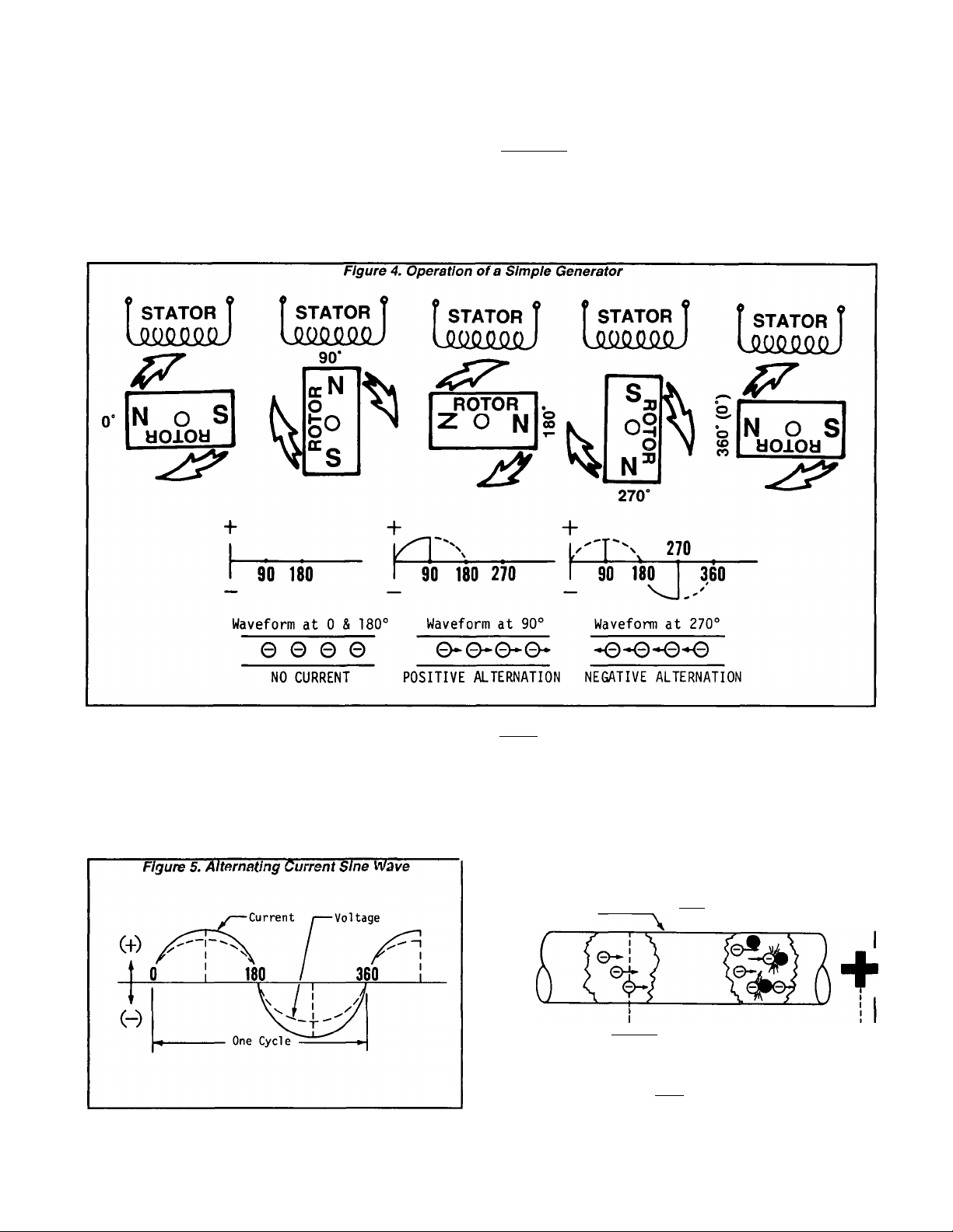
See Figure 4. The current alternates according to the
position of the Rotor’s poles in relation to the position of
the Stator. At 0* and again at 180*, no current flow Is
produced. At 90’ of Rotor rotation, current flow reaches
a maximum positive value. Rotor rotation to 270’ brings
another maximum flow of current. However, at 270’ the
current flow has reversed In polarity and now flows in the
opposite direction.
Electrical Units
AMPERE;
The rate of electron flow in a circuit is represented by
the AMPERE. The ampere is the number of electrons
flowing past a given point at a given time. One AMPERE
Is equal to Just slightly more than six thousand million
billion electrons per second.
With alternating current (AC), the electrons flow first
In one direction, then reverse and move In the opposite
direction. They will repeat this cycle at regular intervals.
A wave diagram, called a “sine wave“ shows that current
goes from zero to maximum positive value, then reverses
and goes from zero to maximum negative value. Two
reversals of current flow Is called a cycle. The number of
cycles per second Is called frequency and is usually
stated in "Hettz".
Page 1.1-2
VOLT:
The VOLT is the unit used to measure electrical PRESSURE, or the difference In electrical potential that causes
electrons to flow. Very few electrons will flow when
voltage is weak. More electrons will flow as voltage
becomes stronger. VOLTAGE may be consdiered to be
a state of unbalance and current flow as an attempt to
regain balance. One volt is the amount of EMF that will
cause a current of 1 ampere to flow through 1 ohm of
resistance.
Figure 6. Electrical Units
Conductor of a
Circuit
AMPERE - Unit measuring rate of
L.
OHM - Unit measuring resistance
or opposition to flow
current flow (nunfcer of elec
trons past a given point)
■ VOLT - Unit measuring force or
_____
difference in potential
causing current flow
Page 7
Section 1.1- GENERATOR FUNDAMENTALS
OHM:
The OHM Is the unit of RESISTANCE. In every circuit
there Is s natural resistance or opposition to the flow of
electrons. When an EMF Is applied to a complete circuit,
the electrons are forced to flow In a single direction
rather than their free or orbiting pattern. The resistance
of a conductor depends on (a) Its physical makeup, (b)
Its cross-sectional area, (c) Its length, and (d) Its temper
ature. As the conductor’s temperature Increases, Its re
sistance Increases In direct proportion. One (1) ohm of
resistance will permit one (1) ampere of current to flow
when one (1) volt of electromotive force (EMF) Is applied.
Ohm’s Law
A definite and exact rela
tionship exists between
VOLTS, OHMS and AMPERES.
The value of one can be calcu
lated when the value of the
other two are known. Ohm’s
Law states that In any circuit
the current will Increase when
voltage Increases but resis
tance remains the same, and
current will decrease when re
sistance Increases and volt
age remains the same.
If AMPERES Is unknown while VOLTS and OHMS are
known, use the following formula:
i AMPS
\(l)
OHMS j
(R)y
The magnetic field around the conductor Induces elec
tromotive forces that cause current to keep on flowing
while voltage drops. The result Is a condition In which
voltage leads current When a conductor Is formed Into
a coll, the magnetic lines of force are concentrated In the
center of the coll. This Increased density causes an
Increase In magnetically Induced EMF without Increas
ing current Thus, colls cause Inductive reactance.
Inductive reactance can also be caused by placing an
Inductlonmotoronthe circuit which utilizes the current’s
magnetic field for excitation.
AMPERESs VOLTS
■ÖHMS"
If VOLTS is unknown while AMPERES and OHMS are
known, use the following formula:
VOLTS 3 AMPERES X OHMS
If OHMS Is unknown but VOLTS and
AMPERES are unknown, use the following:
OHMS: VOLTS
AMPERES
Reactance in AC Circuits
GENERAL:
When direct current (DC) Is flowing, the only opposi
tion to current flow that must be considered is resistance
(ohms). This Is also true of alternating current (AC) when
only resistance type loads such as heating and lamp
elements are on the circuit In such a case, current will
be In phase with voltage- that Is, the current sine wave
will coincide In time with the voltage sine wave.
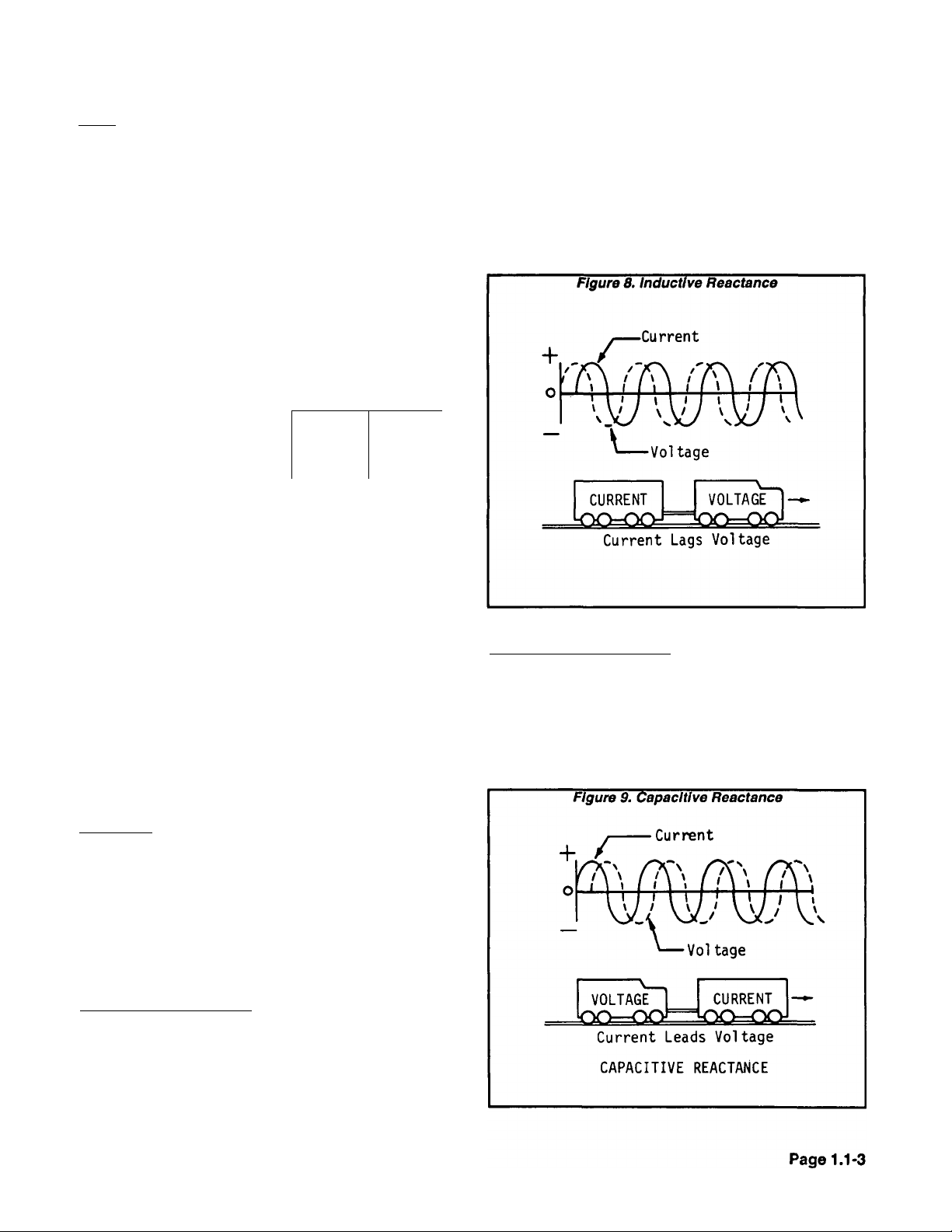
However, two factors In AC circuits called INDUCTIVE
and CAPACITIVE REACTANCE will prevent the voltage
and current sine waves from being In phase.
INDUCTIVE REACTANCE:
This condition exists when current lags behind volt
age (Figure 8). As current flows In a circuit, magnetic
lines offeree are created at right angles to the conductor.
The continuous changes In current value (from positive
to negative) cause these magnetic lines to collapse and
build up continuously.
CAPACITIVE REACTANCE:
This condition occurs when current leads voltage (Fig
ure 9). It might be thought of as the ability to oppose
change In voltage. Capacitance exists In a circuit when
certain devices are (a) capable of storing electrical
charges as voltage Increases and (b) discharging these
stored charges when the voltage decreases.
Page 8
Section 1.1- GENERATOR FUNDAMENTALS
introduction to CCG’s
WHAT IS A "CCG"?:
The initials “CCG” stand for “computer con
trolled generator“. Such units are different from
conventional generators in that the performance of
the engine and AC generator are more accurately
matched over a wide range of power needs. The
CCG’s provide greater efficiency of both the engine
and the generator while maintaining electrical out
put within an acceptable voltage and frequency
band.
CCG units have the ability to operate the engine
over a wide range of speeds, while conventional
generators will deliver correct AC frequency and
voltage only at a fixed rpm. The unit’s electrical
output is fed through an AC-AC converter which
reconstructs electrical waveforms to the correct
output frequency.
Unlike conventional AC generators, the CCG can
match engine speed to load requirements. This
provides several advantages, as follows:
П Smaller engines can be used to produce more
power than on a conventional generator, since
it can be allowed to run at a higher speed.
□ When the load is reduced, the engine can run
at slower than the usual speeds. This improves
fuel economy and reduces engine noise.
□ The CCG unit can be operated closer to its peak
power point at all times, because output volt
age and current are functions of engine speed.
This allows fora much more compact generator
design.
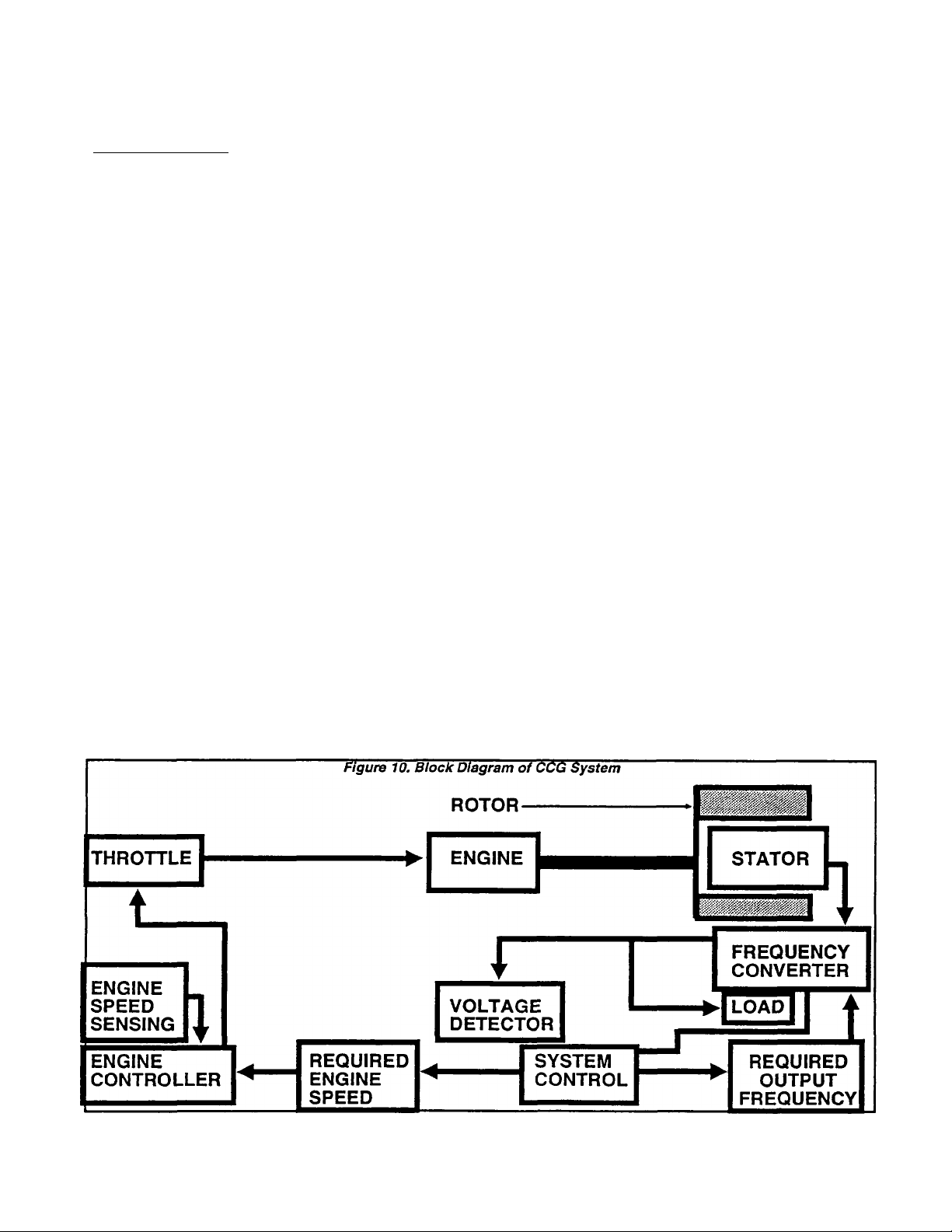
CCG SYSTEM OVERVIEW:
Figure 10 is a block diagram of the CCG system.
The major elements of the system are represented
in the diagram. Operation of the system may be
described briefly as follows:
1. The engine is directly coupled to a permanent
magnet type Rotor, so the Rotor runs at the same
speed as the engine.
2. As the Rotor turns. Its magnetic field cuts across
the Stator windings to induce a voltage into the
Stator.
a. The Stator is a 2-phase type with center tap.
b. Stator AC output frequency Is between 336 and
540 Hertz. This corresponds to engine speeds of
2520 to 4050 rpm.
c. The load requires a nominal AC frequency of
60 Hertz. Thus, the generated frequency Is six to
nine times the desired range.
3. A Frequency Converter changes the high fre
quency output to a useful frequency, I.e., one that
is compatible with load requirements of about 60
Hertz.
4. A Voltage Detector circuit senses load voltage
and signals a System Control circuit.
5. The System Control circuit establishes the RE
QUIRED ENGINE SPEED for correct voltage and
delivers an output to an Engine Controller.
6. The Engine Controller adjusts the engine’s
Throttle to change engine speed and establish the
correct AC output voltage.
7. The following facts should be apparent:
□ LOAD FREQUENCY IS CONTROLLED BY THE
“FREQUENCY CONVERTER“ DEVICE.
□ VOLTAGE IS CONTROLLED BY A “SYSTEM
CONTROL“ CIRCUIT WHICH CHANGES EN
GINE SPEED TO MAINTAIN A CONSTANT
VOLTAGE AT VARYING ELECTRICAL LOADS.
Page 1.1-4
Page 9

Section 1.1- GENERATOR FUNDAMENTALS
Why Variable
Most electrical loads will operate satisfactorily
only within a relatively small voltage band. In order
to provide useful voltage at larger load currents, It
is necessary to increase engine speed.
In conventional AC generators, some form of
voltage regulation Is needed to provide correct
voltage in the full range of load current. This Is
often accomplished by regulating excitation cur
rent to the Rotor (fíelo) which then regulates the
strength of the Rotor’s magnetic field. The voltage
Induced Into the Stator windings Is proportional to
the strength of the Rotor’s magnetic field.
Speed Control?
The CCG uses a Rotor having a fixed and perma
nent magnetic field. The strength of this magnetic
field Is fixed and cannot be regulated.
The output voltage on CCG generators tends to
droop with Increasing electrical loads. The SYS
TEM CONTROLLER maintains a constant AC out
put voltage by Increasing engine and Rotor speed
as the load current increases, to offset this Inherent
voltage droop.
The SYSTEM CONTROLLER also selects the cor
rect number of generator pulses which are com
bined to form each 60 Hertz "half-cycle“.
Page 10

Section 1.1- GENERATOR FUNDAMENTALS
Page 1.1-6
Page 11
Section 1.2- MAJOR GENERATOR COMPONENTS
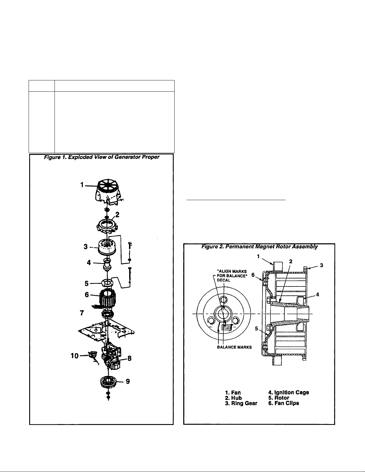
Introduction
Major components of the generator proper are
shown in Figure 1, beiow. Externai sheet metal and
other unrelated components are omitted from the
drawing for clarity. These parts are:
ITEM
1
2
3
4
5
6
7
8
9
10
NOMENCLATURE
Upper Fan Housing
Upper Cooling Fan
Permanent Magnet Rotor
Rotor Hub
Stator Retaining Ring
Stator Assembly
Stator Adapter
Engine
Lower Fan & Flywheel
Stepper Motor
Upper Fan Housing
As its name implies, this component houses and
shields the upper cooling fan. See Figure 1, Item
1.
Upper Cooling Fan
The Cooling Fan draws air Into the generator
through slots in the Upper Fan Housing. It Is fas
tened to and rotates with the Permanent Magnet
Rotor.
Permanent Magnet Rotor
Sixteen permanent magnets have been affixed to
the Rotor. A starter ring gear is welded to the
Rotor. The Rotor and Hub are balanced at the fac
tory as an assembly and must be replaced as an
assembly.
NOTE: The hub MUST be properly aligned during
reassembiy. The mounting bolt, housing opening
and magnet must be properly aligned. In addition,
match marks between the Hub and Rotor must be'
aiigned as indicated by an “ALIGN MARKS FOR
BALANCE” decal. During assembiy, use care to
avoid damage to the Ignition Sensor.______________
DANGERI
THE PERMANENT MAGNET ROTOR PRODUCES
AN EXTREMELY STRONG MAGNETIC FORCE.
USE CARE DURING INSTALLATION TO AVOID
PINCHED FINGERS.
Page 1.2-1
Page 12
Section 1.2- MAJOR GENERATOR COMPONENTS
Rotor Hub
See Figure 2. The Rotor Hub Is balanced with the
Rotor and must be replaced with the Rotor as an
assembly. Part of the engine ignition system is
pressed onto the Hub and can be replaced only as
part of the Rotor and Hub assembly.
Stator Retaining Ring
The Stator Retaining Ring is made of dIe-cast
aluminum. Four hex head capscrews with
lockwashers pass through holes in the Retaining
Ring, to retain the Stator Assembly to the Stator
Adapter (Item 7, Figure 1).
Stator Assembly
The 2-phase Stator is made up of eight (8) wind
ings, with leads brought out as shown in figure 3.
Figure 4 is a schematic representation of each sta
tor winding. Note that there are four (4) power
phase windings (Leads AC2, AC1, SI2, SI1 and 11);
a timing winding (Leads TIM1 and TIM2); a power
supply winding (Leads PS1, PS2); and a dual bat
tery charge winding (Leads 55, 66, 77).
The Stator produces a frequency of 336 to 540
Hertz, which corresponds to engine speeds
between 2520 and 4050 rpm. This means the gen
erated frequency is between six and nine times
the desired frequency of about 60 Hertz.
Stator Adapter
The Adapter Is retained to the engine by means
of four hex head capscrews. The Stator Is retained
to the Stator Adapter and Is “sandwiched'' between
the Adapter and the Stator Retaining Ring.
Lower Fan & Flywheel
The Lower Fan and Flywheel are retained to the
engine PTO shaft by means of a conical washer and
an Ml 6-1.50 hex nut. When assembling, tighten the
flywheel nut to 75 foot-pounds.
Engine
The engine is a single cyclinder, overhead valve
type manufactured by Generac Corporation. De
pending on the specific generator Model Number,
either a GN-190 or a GN-220 engine is used on
NP-30 and NP-40 RV generators.
sponse to changes In AC output voltage. Thus, In
response to decreasing AC output voltages, the
Motor will increase the throttle setting and engine
speed will Increase. Conversely, Increasing AC
output voltages will cause the Motor to decrease
throttle setting and engine speed will decrease.
Figure 3. Stator Pictorial View
-66 (BROWN)-
—77 (BROWN) T1M1 (ORANGE)
—TM2 (GRAY)
-PS1 (BROWN)-
-AC2 (YELLOW)
-AC1 (GRAY)—
-SL1 (ORANGE)—
-----
SL2 (BROWN)-------------
Figure 4. Schematic- Stator Windings
POWER
PHASE 1
POWER
PHASE 2
AC1 aC2
I ! I
POWER I TIMING
SUPPLY I I
PS1 PS2
C «r ® ®
-55 (BLACK)
--------
»<§)
H T1M1 (
PS2 (YELLOW)
■11 (BLUE)
---------
AC2
I (7»CT«r|
II è
b
SL2
è
Stepper Motor
The Stepper Motor (Figure 5, next page) consists
of a stepper motor along with a gear and cam
arrangement which allows motor movement to
change the engine carburetor throttle setting. The
Motor Is controlled by output signals from the Com
puter Control Circuit Board, which calculates the
number of steps the stepper needs to take and
generates the required signals to the Motor. The
circuit board signals the Motor to actuate in re
Page 1.2-2
BATTERY
CHARGE
Page 13
Section 1.2- MAJOR GENERATOR COMPONENTS
The Genistor
GENERAL:
See Figure 6. The GENISTOR is often called a
“frequency converter“ (also see "Introduction to
CCG’s“ on Page 1.1-4). its function is to change the
high frequency AC output of the Stator (336-540
Hertz) to a useful frequency (about 56-60 Hertz).
The Genistor has no intelligence of Its own. It is
simply a high speed switcning device which is
controlled by the CCG circuit board.
Switching signals from the CCG circuit board are
also delivered to the Genistor. These signals
switch the Genistor on and off as required, result
ing In a sine wave output to the load as shown in
Figure 8.
Figure 6. The dtenhtor
GENISTOR THEORY:
The purpose of a “frequency converter“ is to
divide the Stator AC output frequency by an inte
gral factor to provide a useful output frequency.
Each of the four half-phases of the center-tapped
Stator Is Genistor-controlled.
Figure 7 shows the sine wave output from the
2-phase Stator windings. This output Is delivered
to the Genistor switching module.
The CCG Circuit Board
GENERAL:
The CCG circuit board has several functions as
follows:
1. It controls the operation of the “frequency con
verter“ (Genistor).
2. It controls AC output voltage under all load
requirements by controlling engine speed.
3. It protects the system against various faults.
FREQUENCY CONTROL:
The CCG board will adjust the number of alterna
tor cycles In one output cycle to control AC output
frequency. The number of cycles is based on en
gine rpm and the output frequency will be main
tained in the 55-65 Hertz band.
The board uses a "zero crossing" detector to
synchronize an internal clock. The frequency of the
Stator’s waveform is measured and, with
referencve to the required output frequency, a “freguency divisor" is calculated. The circuit board
then signals the Genistor (frequency converter) to
switch on and off at the proper times so that fre
quency Is maintained in the 55-65 Hertz band.
Page 1.2-3
Page 14

Section 1.2- MAJOR GENERATOR COMPONENTS
The CCG
VOLTAGE CONTROL:
The CCG circuit board utilizes a closed-loop,
proportional-derivative controller which regulates
RMS voltage by changing engine speed. The sys
tem maintains output voltage at about 115 volts at
the lowest rpm and 120 volts up to the maximum
rpm.
The board controls a Stepper Motor (Figure 5),
which moves the throttle. The board calculates the
number of steps the Motor needs to take and sig
nals the Motor to move. Motor movement changes
throttle position and changes In engine speed re
sult.
FAULT PROTECTION:
The CCG board has the ability to detect several
fault conditions and shut the engine down, as fol
lows:
1. Overvoltage:- If the output voltage exceeds 127
VAC for longer than 15 seconds, the board will turn
AC output power off and shut the engine down.
2. Undervoitage:- If output remains below about 96
VAC longer than 15 seconds, an overload condition
probably exists. The board will then turn AC output
off and shut the engine down.
3. Overspeed:- if engine speed exceeds 4500 rpm,
shutdown will occur.
4. Failure of the Genistor (frequency converter) will
result in engine shutdown.
5. Loss of output to any circuit connected to the
board will result in engine shutdown.
Circuit Board (Continued)
CIRCUIT BOARD CONI
The board Is equipped with eight (8) connection
points (receptacles). These are identified as
"CONNr through "CONNS". See Figure 9.
CONNECTOR
CONNI
CONNECTIONS:
FUNCTION
Six-pin connector Interconnects
with speed control Stepper Motor.
CONN2
12-pin connector is NOT used on
RV units. An orange jumper wire
is connected across Pins 5 & 11.
CONN3
7-pin connector interconnects with
the Genistor.
CONN4
4-pln receptacle for connection of
the Stator power supply leads
(PS1, PS2) and the Stator timing
leads (TIM1, TIM2).
CONNS Single point connection for Stator
lead No. 11 (blue).
CONN6 Interconnects with the Genistor.
CONN7 Single point connector Is NOT
used on RV units.
CONNS Single point connector for Wire 18B.
Interconnects with Engine Cont
roller circuit board, allows the
CCG board to shut the engine down.
-O
-Ó
Figure 9. the CÔà Circuit Board
0 0 ^
C0NN4
CDNN8 CDNN7
CDNN5
a
u
JSl
_______________
Ì i
□
o
o
CGNN3 CDNN6
lij Itl lil Ui lli'ururuu umuuiuiuniniimui Ui'Ul uul
mfamfsifsifiifgifaifgimfiimfsimmisifCTm ijunj
■~L0r'
Page 1.2-4
Page 15
Section 1.3- OPERATIONAL ANALYSIS
General
Figure 1, below, is a block diagram of the com
puter controlled RV generator. The diagram la In
tended only for the purpose of Illustrating genera
tor operation. Refer to the actual wiring diagram for
wiring interconnections.
Operational Description
1. The PERMANENT MAGNET ROTOR Is directly
coupled to the ENGINE and rotates at the same
speed as the engine.
2. As the ROTOR turns, its magnetic field cuts
across a number of STATOR windings, to Induce a
voltage Into those windings. A voltage Is induced
Into the following STATOR windings:
a. Phase 1 and 2 of the STATOR POWER WIND
INGS (output leads AC1-AC2 and SL1-SL2).
b. The STATOR POWER SUPPLY WINDING with
output leads PS1-PS2.
c. The STATOR TIMING WINDING (output leads
TIM1-TIM2).
d. STATOR BATTERY CHARGE WINDING with
output leads 55,66 and 77.
Figure 1. Block Diagram- AC Generator System
3. STATOR BATTERY CHARGE WINDING o^ut Is
delivered to the unit battery via a BATTERY
CHARGE RECTIFIER (BCR) and a 1 OHM, 50 WATT
RESISTOR. The circuit Is completed through the
battery to frame ground and back to the BATTERY
CHARGE WINDING via Wire 55.
4. STATOR TIMING WINDING output is delivered to
the CCG CIRCUIT BOARD. The circuit board mea
sures the frequency of the waveform and calcu
lates a "frequency divisor" to maintain a useable
frequency to the CUSTOMER CONNECTION re
gardless of rpm.
5. The STATOR POWER SUPPLY WINDING output
Is delivered to the CCG CIRCUIT BOARD. This is
the power supply for operation of the circuit board
and GENISTOR.
6. STATOR POWER WINDING OUTPUT (Phase 1
and 2) Is delivered to a GENISTOR. The GENISTOR
is a nIgh-speed switching device which is con
trolled by the CCG board.
7. The CCG CIRCUIT BOARD senses voltage and
frequency and then acts to control voltage and
frequency as follows:
STATOR
POWER
WINDING
AC1-AC2
WÀ‘§Ê2
STATOR
POWER
WINDING
SL1-SL2
STATOR
POWER
SUPPLY
WINDING
PS1-PS2
STATOR
TIMING
WINDING
TIM1-TIM2
WIRE18B
.(ENGINE
SHUTDOWN)
STATOR
BATTERY
CHARGE
WINDING
66-77
MAGNETIC
FIELD
PERMANENT
MAGNET
ROTOR
ENGINE
Page 1.3-1
Page 16

Section 1.3- OPERATIONAL ANALYSIS
Operational Description (Continued)
a. The circuit board senses actual voltage and b. The CCG board <
"compares“ it to a pre-set “reference“ voltage of
about 115-120 volts AC.
0) If voltage Is low, the board will signal a STEPPER
MOTOR to change engine throttle setting and In
crease speed until the desired voltage level Is
reached.
If voltage goes high, the board will signal the
STEPPER MOTOR to reduce engine throttle setting
until the desired voltage level Is obtained.
(3) Engine speed Is variable and Is used to control
output voltage and may range from about 2520 to
4050 rpm.
acting on the GENISTOR.
(1) The GENISTOR is a high speed switching
device.
(2) The CCG board signals the Genistor to switch
generator waveforms on and off at the proper
times. In order to maintain a frequency In the
55-65 Hertz band.
8. The CCG circuit board can protect the system
against some faults by shutting the engine down,
wire 18B is the “engine shutdown“ lead that connectcts this system to the Engine Controller circuit
board. See “FAULT PROTECTION“, Page 1.2-4.
controls AC frequency by
Page 1.3-2
Page 17
Section 1.4- INSULATION RESISTANCE
Dirt and Moisture
If moisture Is permitted to remain In contact with the
generator Stator windings, some of It will be retained In
voids and cracks of the winding Insulation. This can
eventually cause a reduction In Insulation resistance and
generator output may be affected.
Winding Insulation In Generac generators Is moisture
resistant. However, prolonged exposure to water, high
humidity, salt air, etc., will gradually reduce the resis
tance of winding Insulation.
Dirt can make the problem even worse, since It tends
to hold moisture Into contact with the windings. Salt, as
from sea air, can also worsen the problem, since salt
tends to absorb moisture from the air. When salt and
moisture combine, they make a good electrical conduc
tor.
Because of the detrimental effects of water, dirt and
salt, the generator should be kept as dry and as clean as
possible. Stator windings should be tested periodically
using a Hi-Pot tester or a Megohmmeter. If insulation
resistance is low, drying of the unit may be necessary. If
resistance is still low after drying, the defective Stator
should be replaced.
Insuiation Resistance Testers
One kind of Insulation resistance tester Is shown in
Figure 1, below. Other types are commerlally available.
The type shown has a "Breakdown” lamp which turns on
to indicate an Insulation breakdown during the test.
One common type of tester is the "Megohmmeter"
which measures resistance in "Megohms".
NO. COLOR CONNECTS TO
U
77
66
55
SL2
SL1
AC2
AC1
PS1
TIM1
PS2
TIM2
Blue
Brown
Brown
Black
Brown
Orange
Yellow
Gray
Brown
Orange
Yellow
Gray
Main Circuit Breaker CB1
Battery Charge Rectifier BCR
Battery Charge Rectifier BCR
Grounding Terminal
Genistor fG)
Genistor (G)
Genistor (G)
Genistor (G)
CCG Circuit Board (CCB)
CCG Circuit Board i CCB)
CCG Circuit Board l CCB)
CCG Circuit Board (CCB)
Figure 2. Stator Leads
— 55 (BLACK)-*^)
-66 (BROWN)
— 77 (BROWN) —(ORANGE)
PS2 (YELLOW)
—TM2 (GRAY) -
-PS1 (BROWN)I (BLUE) —«0)
-AC2 (YELLOW)
-AC1 (GRAY)—
-SL1 (ORANGE)^—
CAUTION!
When using a Megohmmeter or any other tester,
be sure to follow the manufacturer’s instructions
carefully. All Stator leads must be isolated from
other components, especially circuit boards, be
fore performina tests. The high voltages used In
testing Insuiation resistance will damage elec
tronic components.
Stator Leads
The following leads are brought out of the Stator and
connected to various components in the unit:
-----
SL2 (BROWN)
-------------
■^0
Preparation for Tests
See Stator leads CHART above. Disconnect and Iso
late all Stator leads. ALL STATOR LEADS MUST BE
DISCONNECTED AND ISOLATED BEFORE STARTING
THE TESTS.
Test Aii Stator Windings to Ground
Connect the ends of all Stator leads together. Make
sure none of the leads are touching any terminal or any
part of the generator.
Connect one Tester probe to the Junction of all Stator
leads; the other Tester probe to a clean frame ground on
the Stator. Apply a voltage of 1000 volts for about 1
second.
Follow the tester manufacturer’s Instructions care
fully. Some "Hl-Pot" testers are equipped with a "Break
down" light which will turn ON to indicate an Insulation
breakdown.
A
"Megger" (Megohmmeter) will Indicate the "meg
s’’ of resistance. Normal Stator winding Insulation
ohms"
resistance is on the order of "millions of ohms" or "meg
ohms". The MINIMUM acceptable Insulation resistance
reading for Stators can be calculated using the following
formula.
MINIMUM INSULATION
RESISTANCE
(In “megohniis")
GENERATOR RATED VOLTS
-
------------------------------------------ +1
1000
Page 1.4-1
Page 18
Section 1.4- INSULATION RESISTANCE
Test All Stator Windings to
Ground (Continued)
EXAMPLE: Generator rated voltage Is "120 VAC".
Divide ■
obtain
the unit Is "1.12 megohms".
120 by 1000 to obtain "0.12". Add “1" to
"1.12 . Minimum Insulation resistance for
.
..............................................■
Test for Shorts Between Windings
Figure 2 on the previous page shows the Stator leads
that are brought out of the Stator. Figure 3 is a schematic
representation of the eight (8) Stator windings. To test
for shorts between windings, proceed as follows:
1. Make sure all Stator output leads are isolated from
each other and from the frame.
2. POWER PHASE TO TIMING WINDINGS:- Connect one
tester probe to Stator lead No. 11, the other test probe to
Stator lead TIM1. Apply a voltage of 1000 volts. The
Tester will Indicate a breakdown if the windings are
shorted together.
3. POWER PASE TO POWER SUPPLY WINDINGS: Con
nect one tester probe to Stator lead No. 11, the other
tester probe to Stator lead PS1. Apply 1000 volts. If a
breakdown Is Indicated, the windings are shorted to
gether.
4. POWER PHASE TO BATTERY CHARGE WINDINGS:Connect one tester probe to Stator Lead No. 11, the other
probe to Stator lead No. 55. Apply 1000 volts. If break
down Is Indicated, the windings are shorted together.
5. TIMING TO POWER SUPPLY WINDING:- Connect one
tester probe to Stator lead No. TM1, the other test probe
to Stator lead No. PS1. Apply 1000 volts. If breakdown is
Indicated, the windings are shorted together.
6. TIMING TO BATTERY CHARGE WINDING:- Connect
one test probe to Stator lead No. TIM1, the other test
probe to Stator lead No. 55. Apply 1000 volts. If break
down is Indicated the windings are shorted together.
7. POWER SUPPLY TO BATTERY CHARGE WINDING:Connect one test probe to Stator lead No. PS1, the other
probe to Stator lead No. 55. Apply 1000 volts. If break
down is indicated, the windings are shorted together.
Results of Tests
1. If testing Indicates that Stator windings are shorted to
ground, the Stator should be cleaned and dried. The
Insulation resistance tests should then be repeated. If,
after cleaning and drying, the Stator again fails the test,
replace the Stator assembly.
2. If testing Indicates that a short between windings
exists, clean and dry the Stator. Then, repeat the tests. If
Stator fails a second test (after cleaning and drying),
replace the Stator assembly.
Cleaning the Generator
GENERAL:
If testing indicates that the insulation resistance is
below a safe value, the winding should be cleaned.
Proper cleaning can be accomplished only while the
generator is disassembled. The cleaning method used
should be determined by the type of dirt to be removed.
Be sure to dry the unit after it has been cleaned. An
electric motor repair shop may be able to assist with
cleaning. Such shops are often experienced in special
problems (sea coast, marine, wetland applications, etc.).
Figure 3. Schematic- Stator Windings
pravm ппушт|
POWER
PHASE 1
POWER ^
PHASE 2
BATTERY
CHARGE
AC1
I
SL1
à
POWER
f
SUPPLY
PS1 PS2 .
О ^ О
11
AC2
h
SL2
h
TIMING
TIMI T1M2
USING SOLVENTS FOR CLEANING:
A solvent is generally required when dirt contains oil
or grease. Only petroleum distillates should be used to
clean electrical components. Recommended are safety
type petroleum solvents having a flash point greater than
100’ F. (38* C.).
Use a soft brush or cloth to apply the solvent. Use care
to avoid damaging magnet wire or winding Insulation.
After cleaning, dry all components thoroughly with mois
ture-free, low pressure compressed air.
DANGER!
DO NOT WORK WITH SOLVENTS IN ANY EN
CLOSED AREA. ALWAYS PROVIDE ADEQUATE
VENTILATION. FIRE, EXPLOSION OR OTHER
HEALTH HAZARDS MAY EXIST UNLESS ADE
QUATE VENTILATION IS PROVIDED. WEAR EYE
PROTECTION. WEAR RUBBER GLOVES TO PRO
TECT THE HANDS.
CAUTIONI
Some generators use epoxy or polyester base
winding varnishes. Use solvents that do not at
tack such materials.
Page 1.4-2
Page 19

Section 1.4- INSULATION RESISTANCE
Drying the Generator
GENERAL:
If testing Indicates that the insulation resistance of a
winding Is below a safe value, the winding should be
dried before operating the unit Some recommended
drying methods include (a) heating units and (b) forced
air.
HEATING UNITS:
If drying Is needed, the generator can be enclosed In
a covering. Heating units can then be Installed to raise
the temperature about 15’-18* F. (8*-10* C.) above ambi
ent.
FORCED AIR:
Portable forced air heaters can be used to dry the
generator. Direct the heated air Into the generator’s air
intake openings. Run the unit at no-load. Air temperature
at the point of entry Into the generator should not exceed
150* F. (66* C.).
Page 20

Section 1.4- INSULATION RESISTANCE
Page 1.4-4
Page 21
Section 1.5- COMPONENTS TESTING
Introduction
Problems that occur In the computer-controlled
RV generator generally Involve the following sys
tems or components:
1. The engine.
2. The Speed Control System.
3. The AC Generator.
4. The Genistor.
5. Battery Charge Circuit.
6{ CCG Circuit Board.
7. Wiring Harness and Front Panel.
This Section will discuss test procedures for the
following components. Also see Part 8 of this
Manual, “TROUBLESHOOTING".
1. The AC Generator (Stator).
2. The Genistor.
3. Battery Charge Circuit.
4. CCG Circuit Board.
Stator Assembly
GENERAL:
For additional information on the Stator, refer to
the following:
1. “ Stator Assembly“ on Page 1.2-2.
2. Section 1.4, “INSULATION RESISTANCE“.
SYMPTOMS OF STATOR FAILURE:
A. If the engine starts but the Stepper Motor does
not move, and shutdown occurs after several sec
onds, look for the following:
1. Broken or shorted Power Supply winding
(Wires PS1 and PS2).
2. Broken or shorted Timing winding (Wires TIM1
and TIM2).
NOTE: If the Power Supply windina Is shorted to
ground, a burned area on the CCG circuit board
mircult board ground track) may be visible. If the
Timing winding Is shorted to ground, the circuit will
probably be damaged but bum-up may not be vls-
A short circuit between windings.
□
□
NOTE: The resistance of Stator windings Is very
low. Some meters will not read such alow resis
tance and will simply Indicate “continuity". Recom
mended Is a high quality, digital type meter capable
of reading very low resistances.
TESTING POWER PHASE WINDINGS:
A. Refer to Figures 1 and 2. To test the Power
Phase windings for an open circuit condition, pro
ceed as follows:
1. Disconnect the following wires:
a. Lead “AC1" (Gray) at the Genistor.
b. Lead “AC2” (Yellow) at the Genistor.
c. Lead “SL1" (Orange) at the Genistor.
d. Lead “SL2" (Brown) at the Genistor.
e. Lead No. 11 (Blue) at the Main Circuit Breaker
(CB1).
2. Make sure all of the disconnected leads are
isolated from each other and are not touching the
frame during the test.
3. Set a VOM to its "Rxl" scale and zero the
meter.
4. Connect one VOM test lead to Lead No. 11
. Then, connect the remaining test lead as
K
s:
a. To Lead AC1 and note the resistance reading,
b. To Lead AC2 and note the resistance reading,
c. To lead SL1 and note the resistance reading,
d. To lead SL2 and note the resistance reading.
NOMINAL RESISTANCE- POWER PHASE WINDINGS
Figure 1. Schematic- Stator Windings
POWER
PHASE 1
POWER
PHASE 2
0.30 to 0.42 ohm
B. If the engine shuts down but speed did NOT
exceed 4500 rpm, look for the following:
1. One of the main windings (Power Phase 1 or
2) is open.
2. One of the main windings (Power Phase 1 or
2) is shorted to ground.
TESTING THE STATOR WITH A VOM:
A Volt-Ohm-Milliammeter (VOM) can be used to
test the Stator windings for tne following faults:
□ An open circuit condition.
□ A "short-to-ground“ condition.
BATTERY
CHARGE
nSGfiSIPr
PS1
c
POWER
SUPPLY
TIMING
TIMI T1M2
Page 1.5-1
Page 22
Section 1.5- COMPONENTS TESTING
Stator Assembly (Continued)
TESTING POWER PHASE WINDINGS
B. To test the Power Phase windings for a "short-toground* condition, proceed as follows:
1. Make sure all leads are Isolated from each other and
are not touching the frame.
2. Set a VOM to its *Rx10,000" or "RxlK* scale and
zero the meter.
3. Connect one VOM test lead to the terminal end of
Lead" AC1", the other test lead to a clean frame ground
on the Stator.
a. The meter should read "infinity".
b. Any reading other than "infinity" indicates a
"short-to-ground* condition.
TESTING POWER SUPPLY WINDINGS:
A. To test the Power Supply winding for an open circuit
condition, proceed as follows:
1. Disconnect the 4-pin connector from "CONN4" of
the CCG circuit board. See Rgure 3.
a. Stator lead "PS1* (Brown) connects to Pin 1 of
the connector.
b. Stator lead "PS2* (Yellow) connects to Pin 3 of
the connector.
2. Set a VOM to its *Rx1* scale and zero the meter.
3. Connect one VOM test lead to Pin 1 (Lead PS1Brown), the othet test lead to Pin 3 (Lead PS2-Yellow).
The meter should indicate the resistance of the Power
Supply winding.
NGS (CONT’D): NOTE: Any reading other than "Infinity'' Indicates
the winding Is shorted to ground. If winding Is open
or shorted, the Stator should be replaced.
TESTING THE TIMING WINDING:
A. To test the Stator Timing winding for an open circuit
condition, proceed as follows:
1. Disconnect the 4-pin connector from "CONN4" of
the CCG circuit board. See Rgure 3.
a. Stator lead TIM1 (Orange) connects to Pin 2 of the
4-pin connector.
b. Stator lead TIM2 (Gray) connects to Pin 4 of the
4-pin connector.
2. Set a VOM to its *Rx1 * scale and zero the meter.
3. Connect one VOM test lead to Pin 2 (Lead TIM1Orang^; connect the other test lead to Pin 4 (Lead
TIM2- Gray). The meter should Indicate the Stator
Timing winding resistance.
B. To test the Timing winding for a "short-to-ground"
condition, proceed as follows:
1. Set the VOM to its "Rx10,000* or "Rx1K" scale and
zero the meter.
2. Connect one VOM test lead to Pin 2 of the 4-pin
connector (Lead TIMI-Orange).
3. Connect the other test lead to a clean frame ground
on the Stator. The meter should read "Infinity". Any
reading other than "Infinity" Indicates the Timing
winding is shorted to ground.
Figures. "CONN4“4-Pin Connector
NOMINAL RESISTANCE
STATOR TIMING WINDING
0.35-0.44 ohm
NOMINAL RESISTANCE
POWER SUPPLY WINDING
0.35-0.44 ohm
B. To test the Power Supply winding for a “short-toground" condition, proceed as follows:
1. Set the VOM to its “Rx10,000" or "RxlK" scale and
zero the meter.
2. Connect one VOM test lead to Pin 1 (Lead PS1Brown). Connect the other test lead to a clean frame
ground on the Stator. The meter should read "infinity".
Page 1.5-2
SHORT CIRCUIT BETWEEN WINDINGS:
To test for a short circuit between windings, proceed
as follows:
1. Set a VOM to its "Rx10,000" or "RxlK" scale and
zero the meter.
2. Connect one meter test lead to Stator lead PS1
(Brown).
3. Connect the remaining test lead to Stator lead AC1
(Gray). The meter should read "Infinity*. Any reading
other than "infinity" indicates a shorted condition and
the Stator should be replaced.
Page 23
Section 1.5- COMPONENTS TESTING
4. Connect one VOM test lead to Stator lead AC1,
the other test lead to Stator lead 77. The VOM
should read "Infinity“.
5. Connect one VOM test lead to Stator lead AC1,
the other test lead to Stator lead TIM1. The meter
should read “Infinity”.
6. Connect one test lead to Stator lead PS1, the
other to Stator lead TIM1. “Infinity" should be
Indicated.
7. Connect one test lead to Stator lead PS1, the
other to Stator lead 77. The VOM should read
"Infinity".
8. Connect one VOM test lead to Stator lead TIMI,
the other test lead to Stator lead 77. “Infinity"
should be Indicated.
Genistor
GENERAL:
The “Genistor" or "Triac Module" is the FRE
QUENCY CONVERTER for the generator. For addi
tional Information on the Genistor, refer to "The
Genistor" on Pages 1.2-3 and 1.2-4.
SYMPTOMS OF GENISTOR FAILURE:
If the engine shuts down but speed did not ex
ceed 4500 rpm, the following problems may exist:
1. Loss of the "Gate" connection (G1 through G4)
between the CCG circuit board and the Genistor.
2. Although the correct “Gate" signal Is received
from the CCG board, one or more switches are not
gating.
3. The Genistor is not gating properly, I.e., one or
more switches are permanently turned on.
4. Open circuit or loss of connection(s) between
Stator and Genistor (Leads AC1, aC2, SLI, SL2,
22).
5. Open circuit or loss of connection between
Genistor and CCG circuit board (Leads AC1, AC2,
SL1,SL2).
TESTING THE GENISTOR:
Disconnect ail wires from the Genistor before
attempting to test it.
RESISTANCE READING
"COM" to G1 s 20-60 Ohms
"COM" to G2 > 20-60 Ohms
"COM" to G3 o 20-60 Ohms
"COM" to G4 B 20-60 Ohms
3. Set the VOM to its “Rx1” scale and zero the
meter. Then connect the VOM test leads across
the “COM" terminal and the center screw. The
VOM should read “continuity”.
4. Now, connect the VOM test leads across the fol
lowing terminals and screws:
a. Across AC1 screw to AC1 terminal should
read “continuity”.
b. Across AC2 screw to AC2 terminal should
read “continuity”.
c. Across SLI screw to SLI terminal should read
“continuity”.
d. Across SL2 screw to SL2 terminal should read
“continuity”.
5. Set the VOM to its “Rxl 0,000” or “RxlK” scale
and zero the meter. Then, connect the VOM test
leads across each of the screws. There should be
no continuity between any of the screws (“infini
ty”).
NOTE: The resistance reading between any two of
the screws on the Genistor is in the neighborhood
of about 1 megohm (about 1 million amps). If the
Genistor failed any of the proceeding tests, it
should be replaced.
f^lgure 4. Genistor Test Points
CAUTIONI
DO NOT attempt to test the Genistor until ALL
leads have been disconnected. The genistor
MUST be completely disconnected from the cir
cuit If testing is accomplished with any leads
connected, alftest results are Invalid.
See Figure 4. To test the Genistor, proceed as
follows:
1. Set a VOM to a resistance scale that will allow a
range of about 20-60 ohms to be read. Zero the
meter.
2. Connect one VOM test leads to the "COM" termi
nal and the other test lead to Terminals G1, G2, G3
and G4 one at a time. Read the resistance as the
meter is connected to G1, to G2, to G3, and to G4.
Testing the Battery Charge Circuit
GENERAL:
The Stator Is equipped with
dual battery charge windings.
These windings deliver an AC
output to a Battery Charge Rec
tifier (BCR) which rectifies it
changes It to direct current or
É
C). The direct current Is deliv
ered to the unit battery, to main
tain the battery in a charged
state while the unit Is running.
figure 5,
BATTERY CHARGE
WINDING
Page 1.5-3
BCR
Page 24
Section 1.5- COMPONENTS TESTING
Testing the Battery Charge Circuit
(Continued)
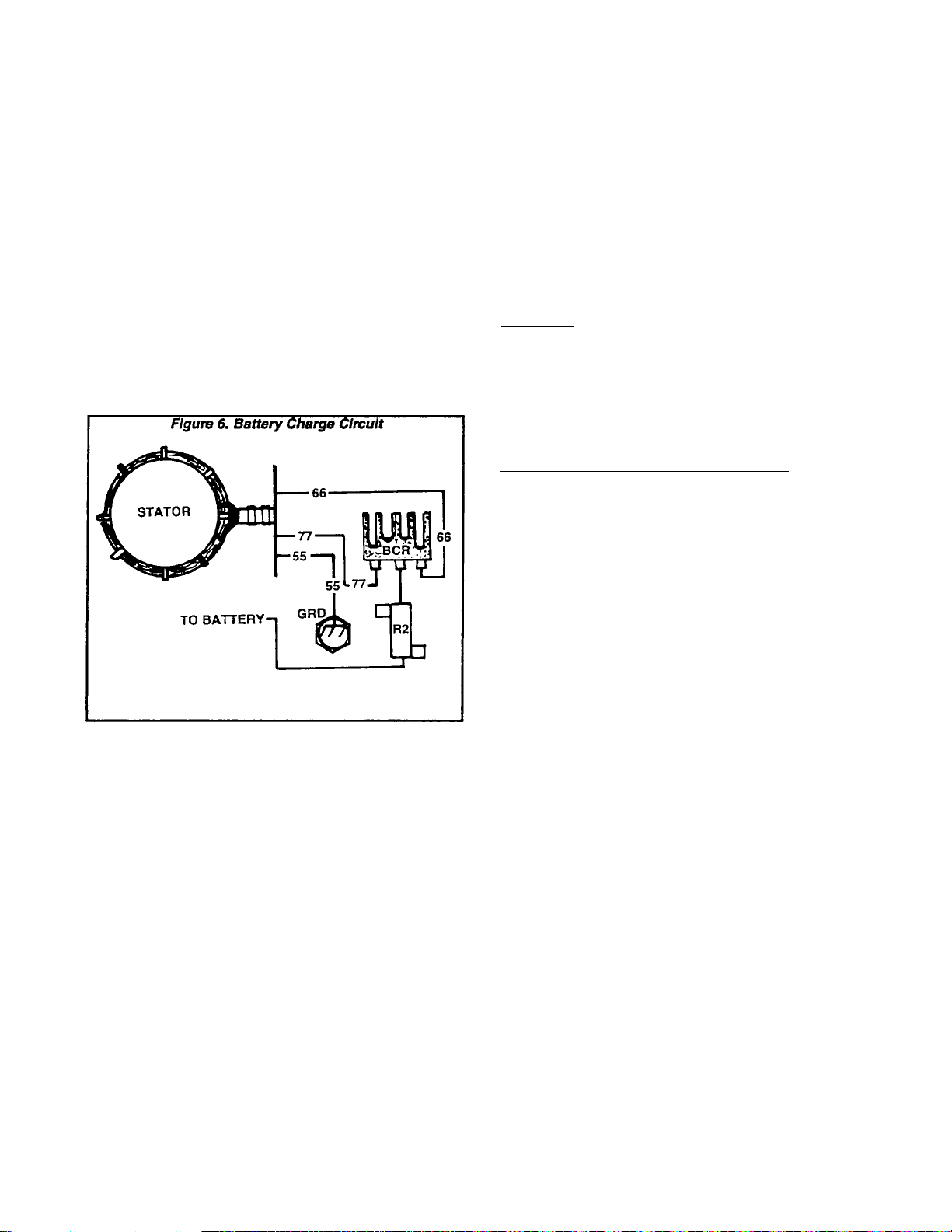
SYMPTOMS OF CIRCUIT FAILURE:
It is difficult to determine if the battery charm
circuit is operating without testing for correct volt
age. If you suspect the battwery charge circuit Is
defective, the following symptoms will usually
point to a cause of the problem. See Figure 6.
1. If no AC voltage can be measured across Stator
connections at the Battery Charge Rectifier (BCR),
an open circuit condition probably exists in Wire 66
(Brown), or Wire 77 (Brown).
2. If AC voltage is available to the Wire 66 and 77
terminals at the battery Charge Rectifier, but no
voltage or a low voltage Is measured between the
BCR’s Wire 55 terminal and ground, the Battery
Charge Rectifier (BCR) Is defective.
TESTING THE BATTERY CHARGE CIRCUIT:
Test the Battery Charge winding as follows:
1. Disconnect Wire 77 at the Battery Charge Recti
fier (BCR).
2. Disconnect Stator output Wire 66 at the Battery
Charge Rectifier (BCR).
3. Disconnect Wire 55.
4. Set a VOM to its ”Rx1" scale and zero the meter.
5. Connect the VOM test leads across Wires 77 and
55, then across Wires 66 and 55. Note the resis
tance reading in both cases. Replace Stator As
sembly, If defective.
BATTERY CHARGE WINDING RESISTANCE
ACROSS WIRES 66 TO 55 s 0.037-0.042 Ohm
ACROSS WIRES 77 TO 55 s 0.037-0.042 Ohm
6. Use a VOM to measure AC voltage at the Wires
66 and 77 terminals of the Battery Charge
Rectifier, with the unit running. If no AC voltage is
measured, an open circuit exists in the wire 66 or
77 circuit.
7. With engine running, use a VOM to check for DC
voltage between the Battery Charge Rectifiers
Wire 55 and frame ground. If AC voltage was pre
sent in step 6, but DC voltage is NOT present in
this stem, the Battery Charge Rectifier (BCR) is
d6f6CtiVG.
Testing the CCG Circuit Board
GENERAL:
It is difficult if not impossible to test the CCG
circuit board in the field. Generally, if the other
components in the AC generator system have
tested good, you may assume that any problem is
In the CCG circuit board.
NOTE: Also refer to “CCG Circuit Board" on Pages
Ï.2-4, 1^-5, and 1^-6.
SYMPTOMS OF CIRCUIT BOARD FAILURE:
1. If the engine starts, but the Stepper Motor does
not move, and engine shuts down after several
seconds, the CCG circuit board’s micro-controiler
may not be operating.
2. A failure of the circuit board’s Stepper Motor
drive can result in the following:
a. Engine starts, but Stepper Motor does not
move. The engine accelerates uncontrollably
and shuts down when engine speed exceeds
4500 rpm.
b. Engine starts, but Stepper Motor does not
move. The following symptoms occur:
(1) Engine appears to operate too slowly.
(2) Engine is not able to handle the load and unit
operates at low AC output voltage.
(3) After several seconds under load, AC output
voltage is turned off (overload condition).
3. If the engine can be started, but shuts down after
several seconds, a timing detection faiiure may
have occured (Timing winding. Wires TIM1, T1M2).
4. if the engine speed and output voltage are erratic
under constant load, but the AC output does not
turn off intermittently, erratic timing detection may
have occured (Timing winding. Wires TIM1, TIM2).
NOTE: Timing detection Involves the circuit
board’s ability to detect "zero crosslrws" of the
sine wave (see “Alternating Current", Pages 1.1-1
and 1.1-2). The CCG clrculfboard must detect both
zero VOLTAGE and zero CURRENT crossings If the
system Is to operate properly. This “zero crossing“
detector Is used to synchronize an Internal clock
on the circuit board. The frequency of the Input
waveform la measured by the circuit board and
checked against a "reference“ frequency. The
board then calculates a frequency divisor. By
counting “zero voltage crossings“, an Internal reterence output polarity Is generated. The Genistor
switch with the maximum potential In the direction
of the Internal reference Is gated.
Page 1.5-4
Page 25

Section 1.5- COMPONENTS TESTING
TESTING THE CIRCUIT BOARD;
There Is no practical way of testing the CCG
circuit board In the field. Read "SYMPTOMS OF
CIRCUIT BOARD FAILURE" carefully. Test the Sta
tor, the Genistor, and the Battery Charge circuit as
outlined In this Section. Also perform a resistance
test of the Stepper Motor (see Part 7, "THE VARI
ABLE SPEED SYSTEM") and observe Its operation
If possible.
Inspect wiring and wiring connections between
the CCG circuit board and the Genistor as follows
(refer to appropriate wiring diagram):
1. Check wires G1 through G4 (and Wire 22) for
proper connections at circuit board and at the
Genistor.
2. Use a VOM to check Wires G1 through G4 (and
Wire 22) for continuity.
3. Check Wires AC1, AC2, SL1 and SL2 (between
circuit board and Genistor) for proper connections.
4. Use a VOM to check Wires AC1, AC2, SL1, SL2
(between circuit board and Genistor) for condlnu-
Ity.
If all tests are completed and no problem Is found
on other components of the system, replace the
CCG circuit board and check unit operation.
Page 1.5-5
Page 26

Section 1.5- COMPONENTS TESTING
Page 1.5-6
Page 27
Section 1.6- CONTROL PANEL
Construction
The panel Is constructed of sheet metal and Includes
a panel box, a panel back cover and a front control panel.
The panel box Is retained to an enolne-generator divider
plate by five MS screws. Removal of these screws will
permit the panel to be removed from the divider plate and
set out of the way with connecting wires still attached.
This will allow access to components housed In the
control panel.
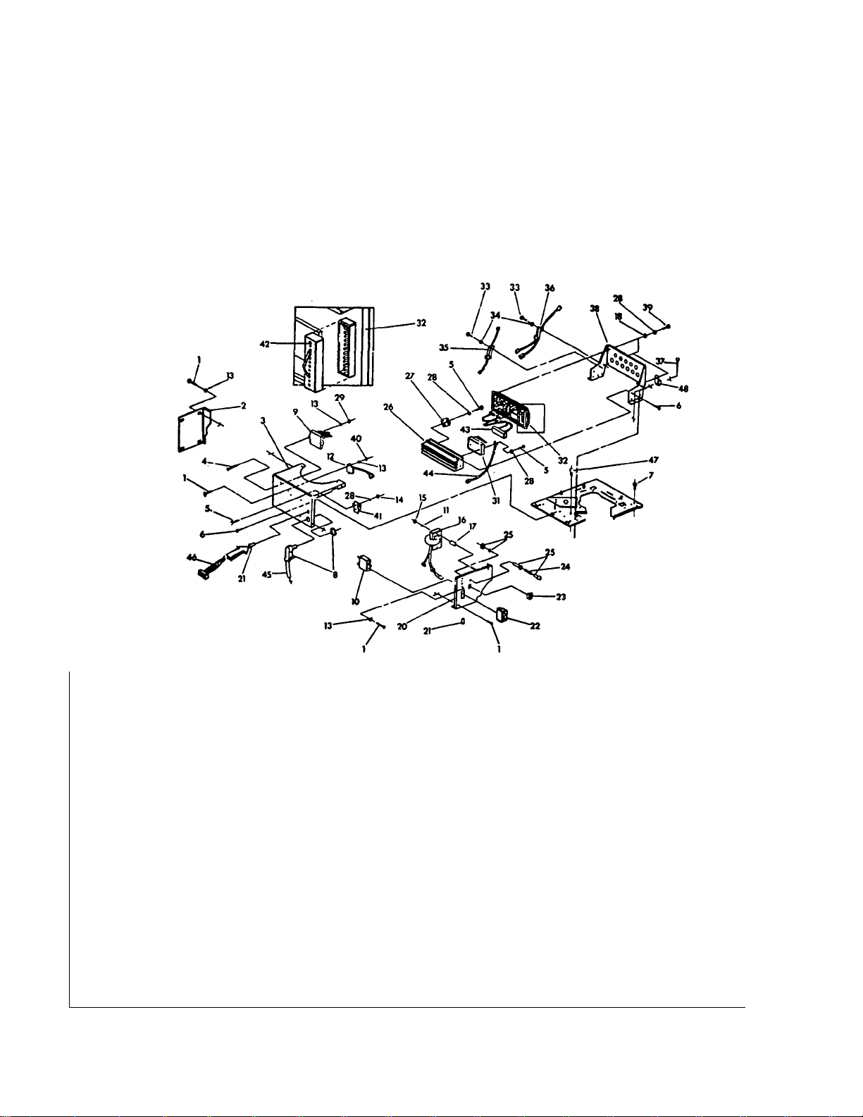
Figurer 1. Exploded View of Control Panel
Components
A heat sink bracket Is attached to the engine-generator
divider plate, for attachment of a heat sink to which a
CCG circuit board and Genistor are mounted. See Items
26,31,32 and 38 In the Exploded View of Control Panel.
Other components are also shown In the Exploded View.
Many of tnese components are part of the "ENGINE
ELECTRICAL SYSTEM" (Part 6 of this manual).
ITEM
1
2
3
4
5
6
7
8
9
10
11
12
13 8
14
15
16
17
18
20
21
22
23
24
25
QTY
6
1
1
2
5
8
1
1
1
1
2
1
2
2 M6 Hex Nut
1
2
4
1
2
1
1
1
1
M5 Pan Head Machine Screw
Engine Controller Circuit Board
DESCRIPTION
Back Panel Cover
Control Panel Box
No. 10-32 Pan Head Screw
M4 Pan Head Screw
M5 Screw
Snap Bushing
90’ Connector
25 amp circuit breaker
M6 Lockwasher
Ignition Module 38
M5 Lockwasher
M4 Hex Nut
Ignition Coll Assembly
Ignition Coll Spacer
No. 8 Flatwasher 44 1 Ground Wire
Front Control Panel 45 1
Snap Bushing 46
Start-Stop Switch
Fuel Primer Switch
15 amp Fuse
Fuse Holder
ITEM
26 1
27 1
28 9
29 2
31 1
32 1 CCG Printed Circuit Board
33 4 M3 Pan Head Screw
34 4 M3 Lockwasher
35
36 1 500 ohm Power Resistor
37 4 M6 Screw
39 4
40 2
41 1 Terminal Block
42
43 1 Genistor Harness
47
48 2 Wiring Harness Clamp
49 1 Panel Harness (Not Shown)
QTY
1 1 ohm Power Resistor
1 Heat Sink Bracket
1 12-pln Connector
1 Remote Panel Harness
1
DESCRIPTION
Heat Sink
Battery Charge Rectifier
M4 Lockwasher
No. 10-32 Hex Nut
Genistor
M4 Pan Head Screw
M5 Hex Nut
Customer Wiring Harness
Snap Bushing
Page 1.6-1
Page 28

Section 1.6- CONTROL PANEL
Page 1.6-2
Page 29
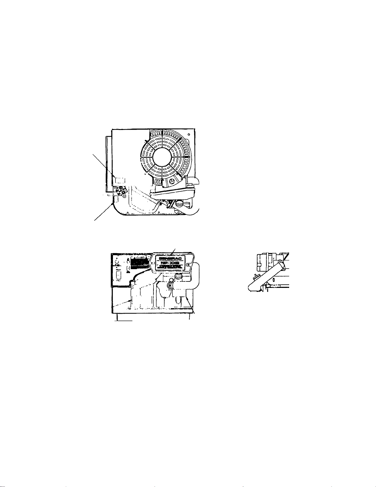
Section 1.7- SHEET METAL
See ‘Exploded View of Sheet Metal" on next page. A
General
DIVIDER PLATE (Item 1 )separate8 the AC generator com
ponents from the engine. The engine Itself Is enclosed
by a BASE HOUSING WRAPPER (ftem 4), a FRAME (Item
24), and a BELLY PAN (Item 23). These components are
sealed by means of rubber SEALS (Items 3), to prevent
the escape of gases.
NP-30/NP-40 Generator
CONTROL PANEL
BOX
DIVIDER PLATE
The LOWER FAN attaches to the engine shaft and Is
enclosed In a LOWER FAN HOUSING (Item 19). Air Is
drawn Into the enclosed area around the engine and
forced out of the LOWER FAN HOUSING.
Removal of sheet metal will be necessary for many
repairs and for replacement of most parts.
ROCKER COVER
COVER
OIL FILTER buy il
AIR CLEANER
/
I ...r
OIL FILL TAG
ionoanjiiJ
Page 1.7-1
Page 30

Section 1.7- SHEET METAL
Parts List for Exploded View of Sheet Metal
ITEM
1 1
2
3
4
5 26
6
7
8
9 5
10
12 1
13
14 1 3/8"-16 Capscrew 38 1 Snap Bushing
15
16
17
18
19
20
21 1
22 1
23
24
25
QTY
Engine-Generator Divider Plate
1 Engine Upper Wrapper
1 Rubber Seal
1
2 Customer Mounting Ralls
4 M8 Lockwasher 32 1 Starter Contactor Insulator Boot
4
7 M6 Lockwasher 35 4
1
1 3/8” Lockwasher 39
1 3/8” Hex NHut 40
1 Air Outlet Deflector 41 1
1 Exhaust Muffler
1
1 45 1 Grounding Strap
1 Belly Pan 49 1 Muffler Lower Insulation
1
1
DESCRIPTION ITEM QTY DESCRIPTION
Grounding Strap
1/4” Lockwasher
Seal Retainer
M8 Flatwasher
No. 8 Hex Nut
M6-1.00 Capscrew
Lockwasher
Muffler Heat Shield
Base Housing Wrapper
M5 Screw 30
M8-1.25 Capscrew
M8-1.25 Capscrew
Spark Arrestor
Exhaust Clamp
Lower Fan Housing
Carburetor Baffle SKlrt
Rocker Cover Cover
Spark Plug Side Skirt 48
Frame
Grounding Strap
26 1
27 1 Fuel Pump
28 2 Barbed 90* Fitting
29
31
33 1 Oil Filter Opening Seal
34 1
36 1 Fuel Line
37
42
44
47
50 1 Muffler Upper Insulation
3 1/4”-20 Hex Nut
3
1 Starter Contactor
2 Hose Clamp
7 Lockwasher
1 No. 8 Hex Nut
2
1
1
1 Muffler Hanger Bracket
Page 1.7-2
Page 31

Section 1.7- SHEET METAL
Exploded View of Sheet Metal
g 53 s ■«
Page 1.7-3
Page 32

Section 1.7- SHEET METAL
Page 1.7-4
Page 33

SECTION
TITLE
Part 2
ENGINE
MECHANICAL
COMPUTER
CONTROLLED
VARIABLE
SPEED RV
GENERATORS
Series NP-30G and NP-40G
2.1
2.2
2.3
2.4
GENERAL INFORMATION
VALVE TRAIN
PISTON, RINGS, CONNECTING ROD
CRANKSHAFT & CAMSHAFT
Page 34

Section 2.1- GENERAL INFORMATION
Introduction
The engine used on Series NP-30G and NP-40G recre
ational vehicle AC generators Is a Generac Series GN190
or GN220, vertical shaft, single cylinder, overhead valve
type.
These engines are not equipped with a mechanical
engine governor. Instead, variable engine speeds are
controlled by a computer circuit board. The circuit board
signals a stepper motor to move the carburetor throttle
linkage.
4-Cycle Engine Theory
GENERAL;
Series GN190 and GN220 engines require four (4)
strokes or cycles to complete one power cycle. This is
often called the ''4-stroke, 5-event" cycle. The 4 strokes
and 5 events that occur are (1) Intake, (2) compression,
(3) Ignition, (4) power and (5) exhaust
INTAKE STROKE (Figure 1):
The Intake valve is open. The exhaust valve Is closed.
The piston travels downward, creating a suction which
draws the air-fuel mixture from the carburetor Into the
cylinder and Just above the piston.
COMPRESSION STROKE (Figure 2):
As the piston reaches bottom dead center (BOC), the
Intake valve closes. The exhaust valve remains closed,
as well. The piston starts to move outward in the cylinder.
Since both valves are closed, the air-fuel mixture In the
cylinder Is compressed.
POWER STROKE (Figure 3);
Both valves remain closed. At some point before the
piston reached top dead center (TDC), the spark plug
fires to ignite the fuel-air mixture. The piston moves to
its top dead center position and the burning, expanding
gases of combustion force the piston downward.
EXHAUST STROKE (Figure 4):
The expanding gases of combustion force the piston
downward to its bottom dead center (BOC) position. The
exhaust valve then opens, as the piston starts its move
ment toward top dead center (TDC). Piston movement
then forces the exhaust gases out through the open
exhaust valve. The 4-stroke cycle of events then starts
over again.
TIMING;
Valve timing and Ignition timing must be precisely
controlled If the engine Is to operate properly and effi
ciently. Intake and exhaust valves must open and close
In a precise timed sequence If the four strokes are to
occur. Ignition must occur at exactly the correct piston
position, just prior to the start of the power stroke.
Timing of valve opening and closing, as well as of spark
occurence. Is given in relation to the piston position and
the degrees of crankshaft rotation.
Ignition Is timed to occur several degrees before top
dead center (TDC) of the piston, to allow time for the
air-fuel mixture to ignite and start to bum before the
piston reaches top dead center
There must be no leakage past the valves in their
closed position or compression will not develop. Like
wise, there must be no leakage past the piston-
Figure 3. Power Stroke
Page 35

Section 2.1- GENERAL INFORMATION
Recommended Fuels
GASOLINE FUEL SYSTEMS:
For models equipped with a gasoline fuel system, the
use of clean, fresh, UNLEADED, regular grade gasoline
Is recommended. Unleaded gasoline burns cleaner, ex
tends engine life, and promotes better starting by reduc
ing carbon deposits In the combustion chamber.
Leaded "Regular* grade gasoline may be used if un
leaded gasoline Is not available.
The use of gasohol is NOT recommended. If it must be
used, it should not contain more than 10 percent ethanol.
When gasoline containing ethanol is used, special care
Is required when preparing the unit for storage (see
"Storage Instructions").
DO NOT USE GASOLINE CONTAINING METHANOL.
DO NOT MIX OIL WfTH THE GASOLINE.
DANGERl
GASOLINE IS EXTREMELY FLAMMABLE AND
ITS VAPORS ARE EXPLOSIVE. DO NOT PERMIT
SMOKING, OPEN FLAME, SPARKS OR ANY
SOURCE OF HEAT IN THE VICINITY WHILE HAN
DLING GASOLINE. AVOID SPILLAGE OF GASO
LINE ON A HOT ENGINE. THERE MUST BE NO
LEAKAGE OF GASOLINE INTO THE RV GENER
ATOR COMPARTMENT.
GASEOUS FUEL SYSTEMS:
Some RV generator models may be equipped with an
LP or natural gas fuel system. The use of such gaseous
fuels may result in a slight power loss as compared to
gasoline. However, that disadvantage is usually com
pensated for by the many advantages offered by such
fuels. Some of these advantages are:
Recommended Engine Oil
Use a clean, high quality, detergent oil that Is
classified "For Service SC, SD, SE, SF or SG". Use
no special additives with the oil.
G During summer months (above 32* F. or 0* C.), use
SAE 30 oil. SAE 10W-30 oil Is an acceptable substi
tute.
G During winter months (below 32* F. or 0* C.), use SAE
5W-20 or 5W-30 oil.
G DONOTUSESAE10W-40OIL.
Engine crankcase oil capacity without oil filter change
is about 29 fluid ounces (850ml).
Engine crankcase oil capacity (with oil filter change)
is about 1 U.S. quart (946ml).
Change engine oil and the oil filter after the first eight
(8) hours of operation. Thereafter, change engine oil and
oil filter every 50 operating hours.
NOTE: Additional Information on the engine oil
system can be found In Part 5 of this manual,
"Engine Oil and Cooling System".
Storage Instructions
PREPARATION FOR STORAGE:
The engine should be started at least once every
seven (7) days and allowed to run for at least thirty (30)
minutes. If this cannot be done and the engine is to
remain unused longer than thirty (30) days. It must be
prepared for storage. To prepare the unit for storage,
proceed as follows:
1. Start the engine and let It warm up.
2. After engine Is thoroughly warmed up, shut It down.
D A low residue content which results In minimum
carbon formation In the engine,
n Reduced sludge buildup in the engine oil.
n Reduced burning of valves as compared to gasoline.
D No "washdown" of the engine cylinder wall during
cranking and startup.
D Excellent anti-knock qualities,
n A nearly homogenous mixture in the engine cylin
der.
□ Fuel can be stored for long periods without break
down.
DANGERl
GASEOUS FUELS ARE HIGHLY VOLATILE AND
THEIR VAPORS ARE EXPLOSIVE. LP GAS IS
HEAVIER THAN AIR AND WILL SETTLE IN LOW
AREAS. NATURAL GAS IS LIGHTER THAN AIR
AND WILL ACCUMULATE IN HIGH AREAS. EVEN
THE SLIGHTEST SPARK CAN IGNITE THESE
FUELS AND CAUSE AN EXPLOSION. THE USE
OF LEAK DETECTORS IS RECOMMENDED
WHEN GASEOUS FUELS ARE USED. ALL
CODES, STANDARDS AND REGULATIONS PER
TAINING TO THE INSTALLATION AND USE OF
GASEOUS FUELS MUST BE COMPLIED WITH.
NOTE: If the unit Is equipped with a gasoline fuel
system and GASOHOL was used as a fuel, turn off
the supply of fuel to the engine and let It run out of
gas.
3. While engine Is still warm from running, completely
drain the oil. Then, refill with the recommended oil. See
"Recommended Engine Oil".
4. Attach a tag to the engine Indicating the viscosity and
classification of the oil m the crankcase.
5. Remove the spark plug and pour about one (1) ounce
(15ml) of clean, fresh engine oil into the spark plug
threaded opening. Crank the engine several times to
distribute the oil, then Install and tighten the spark plug.
6. Remove the battery and store It In a cool, dry room on
a wooden board. Never store the battery on any concrete
or wood floor.
7. Clean and wipe the generator exterior surfaces.
RETURN TO SERVICE AFTER STORAGE:
To return the unit to service after storage, proceed as
follows:
1. Verify that the correct oil is In the engine crankcase by
checking the tag on the engine (see "Recommended
Engine Oil".) If necessary, drain oil and refill with the
recommended oil.
Page 2.1-2
Page 36

Section 2.1- GENERAL INFORMATION
2. Check the battery. Fill all battery cells to the proper
level with distilled water. DO NOT USE TAP WATER IN
THE BATTERY. If necessary, recharge the battery to a
100 percent state of charge or replace It, If defective.
3. Turn OFF all electrical loads. Start the engine at no-
load and let It warm up.
4. Apply electrical looads to at least 50% of the unit’s
rated capacity.
5. When engine Is thoroughly warmed up, turn off or
disconnect all electrical loads. Then, shut the engine
down.
THE UNIT IS NOW READY FOR SERVICE.
Engine Tuneup
The following procedure may be used as a minor
tuneup. On completion of the procedure, the engine
should run properly. If It does not run properly, additional
checks and repairs are required.
1. Service and repair engine air cleaners, as necessary.
2. Check engine oil level and condition of oil. Add or
change oil as required.
3. Remove shrouding and clean away dirt from the en
gine cylinder head and cooling fins.
4. Check fuel filters and clean or replace as necessary.
5. Replace the spark plug with a Champion RC12YC (or
equivalent) plug.
a. Set spark plug gap to 0.030 Inch (0.76mm).
b. Install new plug and tighten to 13 foot-pounds (1.8
N-m).
c. If a torque wrench Is not available, tighten spark
plug as tight as possible with fingers and then
(1) If plug is RE-USED, tighten about 1/4 turn more
with a wrench.
(2) If plug Is NEW, tighten it about 1/2 turn more with
a wrench.
6. Check that wiring Is free of breaks, abrasions and are
properly routed.
7. Check for spark as outlined in "Ignition“ section of Part
6 of this manual.
8. Run engine, adjust carburetor If necessary and check
operation.
Page 2.1-3
Page 37

Section 2.1- GENERAL INFORMATION
Exploded View of Engine Long Block
ITEM
QTY
DESCRIPTION ITEM
1 1 (jonneciihg Hd'd &
2 1
3
4 2
5
6
7 2
8
10 1
11 1
12
13
14
15 4
16
17 3
18
19
21 1
22 1
23 1
24 1
25 1
26
27
1
1
1
1
Crankshaft & Gear Assembly
1 Sleeve Bearing
2
1
4
1
1
Crank Case Flange Gasket
Oil Pressure Spring Retainer
Oil Pressure Relief valve Ball
4
M6 Screw & Lockwasher
1
Piston Pin 32
Piston Ring Set (STD)
1/4“ Pipe Plug
Breather Cover
Piston
Piston Pin Retainer
Oil Breather Separator
Crankcase Assembly 41
Crankshaft Oil Seal 43 2
Breather Baffle Cup 44
M6 Screw
Lockwasher
Dowel Sleeve
Camshaft Assembky
Cylinder Head Gasket
Oil Pressure Spring
Thread Forming Bolt 54
Oil Filter Adapter
28 6 M8-1.25 Capscrew
29 1
30
2
Oil Pressure Switch
Valve Spring Retainer
NOTE 1Item 36 Includes valve seats and guides.
QTY DESCRIPTION
2
vaive spring
1 Dowel Pin
33 1
34
36 1
37 1
38
39 2
40
42 1
2
1
2 Tappet
1
Inner Oil Pump Rotor
Connecting Rod Bolt
Cylinder Head (see NOTE 1)
Exhaust Valve
Intake Valve
Push Rod
Oil Pickup Screen
Rocker Cover Gasket
Pivot Ball Stud
45
46
2
2
1
Rocker Arm
Rocker Arm Nut
Puch Rod Guide Plate
47 5 Head Bolt
48 1 Rocker Cover
49
50
51 1
52 1
53 2
55 1
56 2
57
58 1
59 1
60
2 Breather Gasket
2 Bolt
Outer OH Pump Rotor
Oil Sump Assembly
Valve Spring Wear Washer
1
Intake Valve Seal
Oil Temperature Switch
M3 Screw
2
M3 Lockwasher
Spark Plug (see NOTE 2)
Oil Filter Adapter Gasket
1
1/4" NPT Pipe Plug
NOTE 2:- Use a Champion RC12YC (or equivakent)
spark plug with gap set to 0.030 Inch (0.76mm).
-------
50
€-J
----------
V4——
-------
5
4—
Page 2.1-4
Page 38

Section 2.2- VALVE TRAIN
Valve Train Components
Valve train components are listed below and shown In
Rgure 1, below.
ITEM
QTY
1
2
3
4 2
5
6 1
7 2
8 2
9 2
10
11
2
2
2
2
1
1
DESCRIPTION
Tappet
Push Rod
Rocker Arm
Pivot Ball Stud
Rocker Arm Jam Nut
Push Rod Guide Plate
Valve Spring
Valve Spring Retainer
Valve Spring Washer
Exhaust Valve
Intake Valve
2. Loosen the rocker arm Jam nuts on the pivot ball studs.
Then, loosen the pivot ball studs. Remove the two pivot
ball studs, the rocker arms and the Jam nuts. Also remove
the push rod guide plate.
NOTE: Keep the Intake valve and exhaust valve
parts separated. Intake and exhaust parts are Iden
tical. However, once a wear pattern has been estab
lished on these parts their tit will be different.
3. Remove the push rods.
4. Remove the cylinder head bolts, then remove the
cylinder head and head gasket
Valve Components Removal
1. The ROCKER ARM COVER Is retained by four M6-1.00
X 12mm screws and lockwashers. Remove the four
screws and lockwashers, then remove the ROCKER ARM
COVER and Its gasket
NOTE: Replace the ROCKER ARM COVER GASKET
each time the COVER Is removed, to ensure proper
sealing.
NOTE: Replace the head gasket every time the head
Is removed. The new head gasket must be free of
nicks and scratches as these could cause leakage.
Figure 4. Cylinder Head Removal
CYLINDER
CYUNDER
HEAD
BOLTS
HEAD
HEAD
GASKET
CRANKCASE
DANGERI
ALWAYS WEAR SAFETY GLASSES WHEN RE
MOVING THE VALVE SPRINGS.
5. See Figure 5, next page. Hold the valve with your
fingers while compressing the spring with your thumb,
then proceed as follows:
Page 2.2-1
Page 39

Section 2.2- VALVE TRAIN
Valve Components Removal (Con
tinued)
a. While the spring is compressed, slide the larger hole
of the valve spring retainer toward the valve stem.
b. With the larger spring retainer hole around the valve
stem, release the spring.
c. Remove the valve spring retainer, the spring and the
spring washer.
6. Remove the Intake and exhaust valves.
7. Clean all parts. Remove carbon from valve heads and
stems.
8. Inspect the valves and valve seats. Service parts as
outlined under ‘Valve Service*.
DESIGN MARGIN: 0.034-0.044 Inch (0.87-1.13mm)
VALVE MARGIN (GN220)
WEAR LIMIT: 0.020 Inch (0.50mm) Maximum
INTAKE VALVE STEM DIAMETER (GN190)
DESIGN DIAMETER: 0.215-0.216 Inch (5.465-5.480mm)
WEAR LIMIT: 0.214 inch (5.435mm) Minimum
INTAKE VALVE STEM DIAMETER (GN220)
DESIGN DIAMETER: 0.274-0.275 inch (6.965-6.980mm)
WEAR LIMIT: 0.273 Inch (6.934mm) Minimum
EXHAUST VALVE STEM DIAMETER (GN190)
DESIGN DIAMETER: 0.214-0.215 inch (5.445-5.460mm)
WEAR LIMIT: 0.213 Inch (5.415mm) Minimum
EXHAUST VALVE STEM DIAMETER (GN220)
DESIGN DIAMETER: 0.273-0.274 Inch (6.945-6.960mm)
WEAR LIMIT: 0.272 Inch (6.909mm) Minimum
NOTE: Design sizes and wear limits of valve train
components can also be found In Part 9 of this
Manual (“SPECIFICATIONS & CHARTS").
VALVE SEATS:
Valve seats are NOT
replaceable. If burned
or pitted, seats can be
reground. Grind seats
at a 45* angle and to a
width of 0.039 Inch
(1.0mm).
Figure 7.
SEAT
^WIDTH
\
,\ V ’1
Valve Service
VALVES:
Replace valves if they
are damaged, distorted
or if the margin is ground
to less than 0.039 Inch
(1.0mm). If the valves
are In useable condition,
use a valve grinder to
grind the faces to a 45*
angle. Check valve stem
diameter.
After the valves have
been reconditioned, they
should be lapped with a
suitable lapping tool and
valve lapping com
pound.
NOTE: Proper lapping of valves and valve seats will
remove grinding marks and ensure a good seal
between the valve and Its seat. Be sure to clean
lapping compound from the valve seats and faces.
VALVE MARGIN (GN190)
DESIGN MARGIN: 0.058-0.060 inch (1.48-1.52mm)
WEAR LIMIT: 0.039 inch (0.98mm) Maximum
STEM —
45"
Figure 6.
0
FACE
--------f
MARGIN
VALVE SEAT WIDTH (GN190 & GN220)
DESIGN WIDTH: 0.034-0.044 inch (0.87-1.13mm)
WEAR LIMIT: 0.064 inch (1.63mm) Maximum
VALVE GUIDES:
Valve guides are permanently Installed in the cylinder
head and cannot be replaced. If the guides become worn
beyond the wear limit, they can be reamed to accomod
ate a 0.020 Inch (0.50mm) oversize valve stem. Use a
straight shank hand reamer or a low speed drill press to
ream valve guides.
VALVE GUIDES (GN190)
DESIGN DIAMETER: 0.216-0.217 Inch (5.505-5.520mm)
WEAR LIMIT: 0.218 inch (5.54mm) Maximum
VALVE GUIDES (GN220)
DESIGN DIAMETER: 0.237-0.2364 inch (6.02-6.005mm)
WEAR LIMIT: 0.238 inch (6.045mm) Maximum
NOTE: After the valve guides have been oversized,
be sure to recut the valve seats so they will align
with the guides.
Page 2.2-2
Page 40

Section 2.2- VALVE TRAIN
Valve Service (Continued)
VALVE TAPPETS!
Valve tappets can be
removed during re
moval of the engine
camshaft. Intake and
exhaust valve tappets
are Identical. However,
once a wear pattern
has been established
the two tappets should
not be Interchanged.
1. Lubricate the valve stems and the valve guides with
engine oil.
2. Install the Intake and exhaust valves through their
respective valve guides in the cylinder head.
a. The exhaust valve has the smaller head with a
diameter of 1.053 Inches (26.75mm).
b. The Intake valve has the larger head, having a
diameter of 1.171 Inches (29.75mm).
c. Valve seat sizes In the cylinder head will match their
respective head sizes.
NOTE: The exhaust valve stem Is also smaller than
that of the Intake valve.
Figure 11. Installation of Intake and Exhaust Valves
VALVE SPRINGS:
Inspect the valve
springs. Measure the
spring free length.
Also, cneck the amount
of force required to
compress the spring to
a length of 1.39 Inch
(35.2 mm). Replace any
damaged or defective
spring.
VALVE SPRING FREE LENGTH
GN190:1.910 Inch (48.48mm)
GN220: 2.074 Inch (52.69mm)
FORCE REQUIRED TO COMPRESS SPRING
TO 1.39 INCH (35.2MM)
GN190:14.8-16.2 lbs (6.7-7.4kg)
GN220:19.8-21.8 lbs (9.0-9.9kg)
Valve Components Installation
After the valve train parts have been Inspected and (If
necessary) serviced. Install them as follows:
BE SURE TO LUBRICATE VALVE
GUIDES A STEMSI
3. Install the valve
spring washers, valve
springs and valve
spring retainers over
the valve guides.
a. Hold the valve
with your fingers
and use your
thumbs to com
press the spring.
b. When the spring
Is compressed suf
ficiently, slide the
spring retainer
small opening over
the valve stem.
c. With the smaller
retainer opening
around the valve
stem, release the spring.
4. After both valves have been retained in the cylinder
head, position a new head gasket and Install the cylinder
head.
NOTE: The head gasket Is coated with a special
substance for better sealing. The gasket must be
free of nicks, scratches and other defects for better
sealing.
5. Install cylinder head bolts. Tighten the head bolts In
the sequence shown to the recommended tightness.
Page 2.2-3
Page 41

Section 2.2- VALVE TRAIN
Valve Components Installation
(Continued)
TIGHTENING TORQUE
CYLINDER HEAD
GN190: 25 foot-pounds
GN220: 29 foot-pounds
6. Place the push rod guide plate Into position on the
head. Then, Install the rocker arm and the pivot ball
stud. The rocker arm Jam nut must be on far enough to
hold the guide plate In position.
NOTE: Do NOT adjust valve clearance at this time.
This will be done later.
Adjusting Valve Clearance
When adjusting valve clearance, the enolne should be
at room tenmerature and the piston shouldbe at top dead
center (TDC) of Its compression stroke (both valves
closed).
VALVE CLEARANCE
GN190 ENGINE
INTAKE VALVE: 0.001-0.003 Inch (0.03-0.07mm)
EXHAUST VALVE: 0.001-0.003 Inch (0.03-0.07mm)
VALVE CLEARANCE
GN220 ENGINE
INTAKE VALVE: 0.001-0.0022 Inch (0.03-0.056mm)
EXHAUST VALVE: 0.0018-0.003 Inch (0.046-0.07mm)
7. Install the push rod with either end against the tappet
a. Place the push rod between the guide plate tabs.
b. Place the rocker arm socket onto end of push rod.
c. Alignment Is correct when push rod ball rests In the
rocker arm socket.
NOTE: The pivot ball stud will be tightened when
the valve clearance Is adjusted. After valve clear
ance has been adjusted, the rocker arm cover will
be Installed.
Adjust the valve clearance as follows:
1. Rotate the crankshaft until the piston Is at top dead
center (TDC) of Its compression stroke. Both valves
should be closed.
2. Loosen the rocker arm Jam nut
3. Use an alien wrench to turn the pivot ball stud while
checking the clearance between the rocker arm and the
valve stem with a feeler gauge.
Page 2.2-4
Page 42

Section 2.2- VALVE TRAIN
4. When valve clearance is correct, hold the pivot ball
stud with the alien wrench while tightening the rocker
arm |am nut with a crow’s foot. Tighten the Jam nut to the
specified torque. After tightening the Jam nut, recheck
the valve clearance to make sure It did not change.
JAM NUT TIGHTENING TORQUE
GN190: 75 Inch-pounds
GN220: 6.3 foot-pounds
Rocker Arm Cover installation
Place a new rocker arm cover gasket into place. Then,
install the rocker arm cover. Finally, retain the cover with
M6-1.00 X 12mm screws.
Page 2.2-5
Page 43

Section 2.2- VALVE TRAIN
Page 2.2-6
Page 44
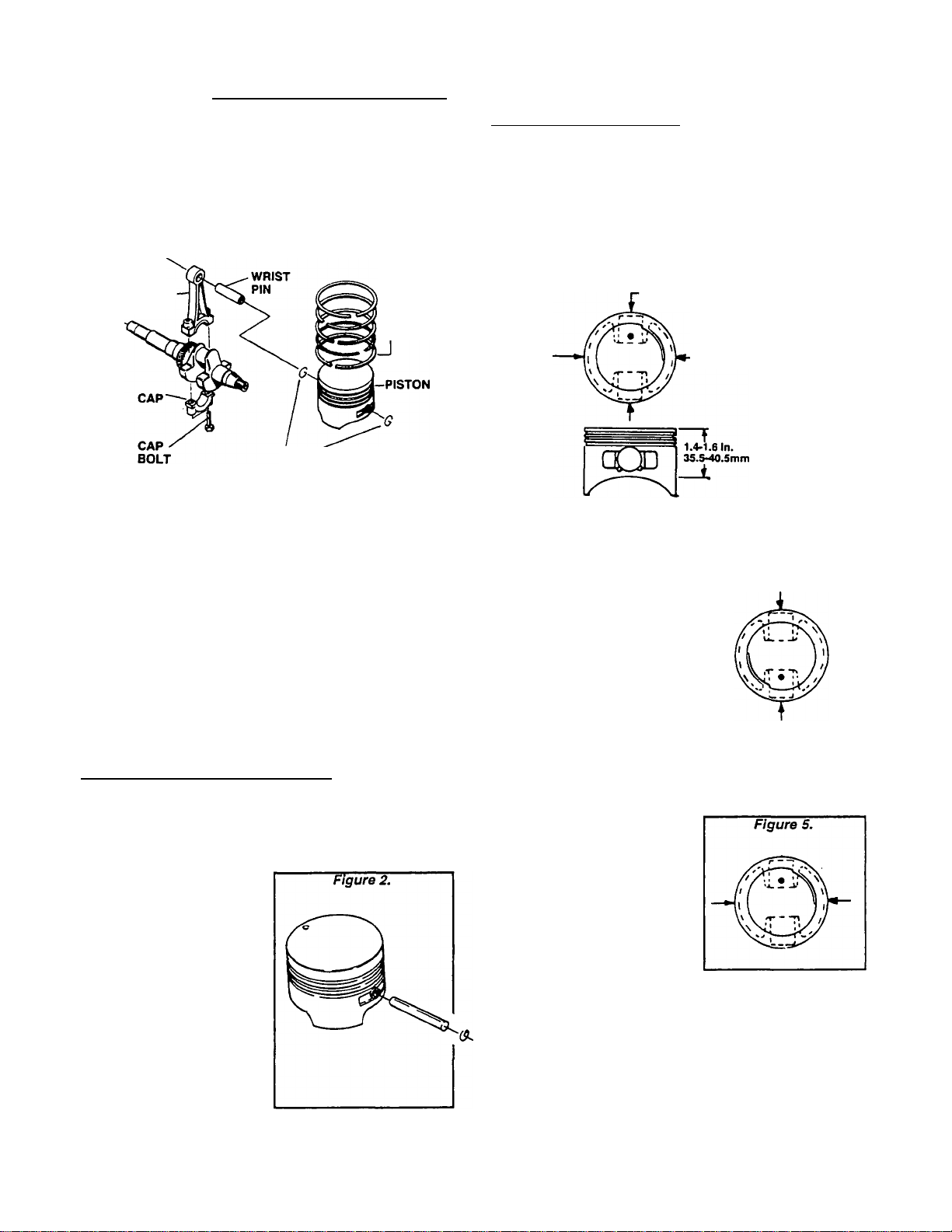
_________
Section 2.3- PISTON, RINGS, CONNECTING ROD
Oversize Piston & Rings
Worn or scored cylinders may be rebored to 0.010
(OJZSmm) or 0.020 (0.50mm) oversize. Pistons and pis
ton rings of matching oversize are available to fit the
rebored cylinder.
Figure 1. Piston, Rings and Connecting Rod
CONNECTING ROD
-RINGS
SNAP"
RING
Prior to Removai
Before removing pistons, rings and connecting rod,
clean all carbon from the cylinder bore. Carbon buildup
In the cylinder bore can cause ring breakage during
piston removal.
Removai
Remove the connecting rod CAP BOLTS and the con
necting rod CAP. Then, push the piston and connecting
rod out through top of cylinder.
CHECK FOR PISTON WEAR:
The piston is slightly elliptical. It’s smaller diam
eter is in line with the wrist pin boss. It’s larger
diameter is 90° from the wrist pin boss.
NOTE: An assembly mark Is provided on the piston.
This mark should face the flywheel end of the
crankshaft (3:00 position) during reassembly.
Figure 3. Elliptical Shape of Piston
2.747-2.748 In.
69.789-69.809mm
2.753-2.754 In.
69.939-89-959tnm
To check the piston for wear, proceed as follows:
1. Minor Diameter:- At a posi
Figure 4.
tion directly in line with the
wrist pin hole, measure from
top of piston down to a dis
tance of 1.4-1.6 Inches (35.5-
40.5mm). This is the "minor"
diameter. Measure at this point
to check for wear.
Piston
REMOVE FROM CONNECTING ROD;
NOTE: An oil hole In the wrist pin area of the piston
helps distribute oil to assist In cooling. The oil hole
also provides an assist In removing the wrist pin
snap ring.
To remove the piston from
the connecting rod, proceed
as follows:
1. Move the snap ring around
until its protruding end is
aligned with the notched out
oil hole. Use needle nose pli
ers to turn the snap ring and
puil it toward you.
2. With one snap ring re
moved, slide the wrist pin
out of the piston boss. This
will separate the piston from
the connecting rod.
PISTON MINOR DIAMETER (GN190 & GN220)
DESIGN DIAMETER: 2.747-2.748 inch (69.789-
69.809mm)
WEAR LIMIT: 2.745 Inch (69.739mm) Minimum
2. Major Diameter:- At a point
90* from the wrist pin bore,
measure down 1.4-1.6 inches
(35.5-40.5mm). This Is the
"major" diameter. Measure at
this point to check for piston
wear. Replace the piston if wear
limits are exceeded.
3. Check wrist Pin for Looseness:- A rough check for
wear in the wrist pin, wrist pin bore in the piston, or wrist
pin bore In the connecting rod is to check for looseness
or play with the piston assembled to the rod. Looseness
or play Indicates a worn wrist pin, or a worn bore in the
piston or connecting rod.
NOTE: Always apply engine oil to wrist pin and Its
bores during Installation. Wrist pin fit Is very close.
Page 2.3-1
Page 45

Section 2,3- PISTON, RINGS, CONNECTING ROD
Piston (Continued)
CHECK PISTON FOR WEAR (CONT’D):
4. Check Wrist Pin for Wear:- Measure the outside diam
eter of the wrist pin. Also measure the inside diameter of
the wrist pin bore in the piston and In the connecting rod.
Also check wrist pin length. Replace any component that
is worn excessively.
WRIST PIN OUTSIDE DIAMETER (GN190 & GN220)
DESIGN DIAMETER: 0.708-0.709 Inch (17.989-
18.000mm)
WEAR UMIT: 0.707 Inch (17.969mm) Minimum
WRIST PIN LENGTH (GN190 & GN220)
DESIGN LENGTH: 2.196-2.213 Inch (55.8-56.2mm)
WEAR LIMIT: 2.193 inch (55.7mm) Minimum
WRIST PIN BORE IN PISTON (GN190 & GN220)
DESIGN DIAMETER: 0.708-0.709 inch (18.000-
18.011mm)
WEAR LIMIT: 0.710 Inch (18.026mm) Maximum
CONNECTING ROD SMALL END I.D. (GN190 & GN220)
DESIGN DIAMETER: 0.709-0.710 inch (18.02-18.03mm)
WEAR UMIT: 0.711 inch (18.05mm) Maximum
5. Ring to Groove Side Clearance:- Clean carbon from
piston ring groov js. Install new rings. Use a feeler gauge
to measure the side clearance between the rings and ring
grooves. If ring-to-groove side clearance exceeds the
stated limits, replace the piston.
Piston Rings
GENERAL:
The following rules pertaining to piston rings must
always be complied with:
□
Always replace piston rings in sets.
□
When removing rings, use a ring expander to pre
vent breakage. Do not spread the rings too far or they
will break.
D When installing the piston into the cylinder, use a
ring compressor. This will prevent ring brteakage
and/or cylinder damage.
n When installing new rings, deglaze the cylinder wall
with a commercially available deglazing tool.
RING DESCRIPTION:
A piston ring SET consists of (a) a top compression
ring, (b) a second compression ring, and (c) an oil ring
assembly. When installing rings, pay close attention to
the following:
G The OIL RING is a 3-piece assembly which consists
of two oil rails and an oil spacer ring. Oil rails have
a rounded face and can be Installed with either side
_ up-
□ The second compression ring has an inside chamfer
which must face UP when installing the ring.
G The top compression ring has a barrel-shaped face
and can be Installed with either side up.
Figure 7. Ring Locations in Piston Grooves
RING TO GROOVE SIDE CLEARANCE (GN190 &
GN220)
0.0004-0.0014 inch (0.012-0.034mm)
Figure 6. Ring to Groove Side Clearance
1ST COMPRESSION RING
TOP COMPRESSION RING
EITHER SIDE UP
2ND COMPRESSION RING
CHAMFER FACES UP
OIL CONTROL RING
EITHER SIDE UP
CHECKING PISTON RING END GAP:
To check piston rings end gap, proceed as follows
(see Figure 8):
1. Locate a point inside the cylinder that Is 2.75 inches
(70mm) down from top of cylinder. This Is approximately
half-way down.
2. Place the ring into the cylinder. Use the piston to push
the ring squarely into the cylinder to the proper depth.
3. Use a feeler gauge to measure the ring end gap. If end
gap is excessive, rebore the cylinder to take oversize
parts.
TOP RING END GAP (GN190 & GN220)
DESIGN GAP: 0.005-0.016 inch (0.15-0.40mm)
WEAR LIMIT: 0.024 inch (0.60mm) Maximum
Page 2.3-2
Page 46

Section 2.3- PISTON, RINGS, CONNECTING ROD
SECOND RING END GAP )GN190 & GN220)
DESIGN GAP: 0.006-0.016 Inch (0.15-0.40mm)
WEAR LIMIT: 0.024 Inch (0.60mm) Maximum
OIL RING END GAP (GN190 & GN220)
DESIGN GAP: 0.015-0.055 Inch (0.38-1.40mm)
WEAR LIMIT: 0.062 Inch (1.60mm) Maximum
Connecting Rod
Tha connecting rod Is man
ufactured of die cast alumi
num. Alignment marks are
provided on the rod and on the
connecting rod cap. Be sure to
align these marks when as
sembling the rod to the crank
shaft. Connecting rod bolts
are of the "washerless" type.
The connecting rod and the
connecting rod cap are a
matched set and must be re
placed as a matched set
INSTALLATION:
Coat the cylinder walls with engine oil, as well as the
crank throw, connecting rod bearing and connecting rod
cap bearing. Then, Install the rod and piston assembly
as follows:
1. Use a ring compressor to compress the rings Into the
piston ring grooves. MAKE SURE ALL RINGS ARE
FULLY COMPRESSED INTO THEIR GROOVES.
2. Guide the connecting rod Into the cylinder, with as
sembly mark on piston toward the flywheel side of en
gine.
3. When the ring compressor contacts top of cylinder,
use a wood hammer handle to gently tap the piston down
into the cylinder.
4. Check that the connecting rod’s large diameter bear
ing is coated with oil, as well as the crank throw and the
connecting rod cap.
5. Guide the large end of the connecting rod onto the
crankshaft Install the connecting rod cap. The match
mark on the cap must be aligned with an Identical mark
on the rod (Figure 10).
6. Install the corinecting rod cap bolts and tighten to the
proper torque.
TIGHTENING TORQUE
CONNECTING ROD CAP BOLTS (GN190 & GN220)
10 foot-pounds (1.36 N-m)
NOTE: The connecting rod can be Installed In either
direction. That Is, the cap marks on the rod and cap
may face toward the Installer or away from the
Installer. The only requirement Is that the assembly
mark on top of piston be toward the flywheel side
of engine.
Assembly and Installation
ASSEMBLY:
Use a ring expander when Installing rings Into the
piston ring grooves. Install the OIL RING ASSEMBLY
first. Then, Install the second compression ring with its
Inside chamfer facing up. Finally, install the top com
pression ring.
When assembling the piston, connecting rod and wrist
pin, the assembly marks on the piston must be toward
the flywheel side of the engine.
Coat the wrist pin, wrist pin bore In piston, and wrist
pin bore in the rod with engine oil. Install one snap ring
Into the piston’s wrist pin bore. Then, assemble the
piston to the rod. Slide the wrist pin through one piston
bore, through the rod bore, and through the second
piston bore until It contacts the snap ring. Then, Install
the second snap ring into the piston bore.
Cylinder Service
INSPECTION:
Check the cylinder for dirty, broken or cracked fins.
Also look for worn or scored bearings, or a scored
cylinder wall. Check the cylinder head mounting surface
for warpage. If the head is warped, it must be replaced.
If the cylinder bore Is worn (as evidenced by excessive
ring end gap), the cylinder should be replaced or rebored
to 0.010 or 0.020 (0.25 or 0.50mm) oversize.
After reboring the cylinder to a specific oversize, In
stall an Identically oversize piston along with identically
oversized rings.
Page 2.3-3
Page 47

Section 2.3- PISTON, RINGS, CONNECTING ROD
Cylinder Service (Continued)
REBORING THE CYUNDER;
Always resize the cylinder bore to EXACTLY 0.010
Inch or 0.020 Inch (0.25 or 0.50mm) over the standard
cylinder dimensions. If this Is done accurately, the ser
vice oversize ring and piston will fit and correct clear
ances will be maintained.
STANDARD CYUNDER BORE DIAMETER
MINIMUM: 2.7560 Inches (70.000mm)
MAXIMUM: 2.7570 Inches (70.025mm)
To rebore the cylinder, use a commercial hone of
suitable size chucked In a drill press having a spindle
speed of about 600 rpm. Use the stones andlubrlcatlon
recommended by the hone manufacturer to produce the
proper cylinder bore finish. Proceed as follows:
1. Start with coarse stones. Center the cylinder under the
drill press spindle. Lower the hone so that the lowest end
of the stone contacts the lowest point in the cylinder
bore.
2. Begin honing at bottom of cylinder. Move the hone up
or down at about 50 strokes per minute, to avoid cutting
ridges In the cylinder wail. Every fourth or fifth stroke,
move the hone far enough to extend it one (1) Inch
beyond the top and bottom of the cylinder bore.
3. Every 30 or 40 strokes, check the bore for size and
straightness. If stones collect metal, clean them with a
wire brush.
4. Hone with coarse stones until the cylinder bore is
within 0.002 Inch (0.05mm) of the desired finish size.
Then, replace the coarse stones with burnishing stones
and continue until bore is within 0.0005 inch (0.01mm) of
the desired size.
5. Install finishing stones and polish the cylinder to its
final size.
6. Clean the cylinder with soap and water. Dry thor
oughly.
7. Replace the piston and rings with parts of correct
oversize.
Page 2.3-4
Page 48

Section 2.4- CRANKSHAFT AND CAMSHAFT
General
Prior to removal of the crankcase cover, gain access
to the engine and generator by removing surrounding
sheet metal as required. See Section 1.6.
Crankcase Cover Removal
Before attempting to remove the crankcase cover,
remove rust, paint and burrs from the power takeoff
end of the crankshaft. This will reduce the possl-
K
of damaging the oil seal In the crankcase cover or
the bearing during cover removal.
To remove the crankcase cover, proceed as follows:
1. Drain oil from the crankcase.
2. Remove the et^lne cylinder head, push rods and push
rod guide plate. See Section 2.2.
3. Remove all bolts that retain the crankcase cover to the
crankcase.
4. Remove the crankcase cover. If necessary, tap lightly
with a soft hammer on alternate sides of the cover.
Camshaft Removal
See Figure 2. Remove the camshaft as follows:
1. Tip the engine over onto the flywheel end of the
crankshaft. Support the engine to prevent end of crank
shaft from resting on the workbench.
2. Reach In with two fingers and hold the tappets up so
they are clear of the camshaft lobes. Then, remove the
camshaft.
3. Remove the two tappets.
4. Remove the outer and Inner oil pump rotors.
Crankshaft Removal
See Figure 3. To remove the crankshaft, proceed as
follows:
1. The engine flywheel must be removed before the
crankshaft can be removed.
2. The piston and connecting rod must be removed.
3. Remove the crankshaft by pulling It straight out of the
crankcase.
Camshaft Inspection
Carefully Inspect the entire camshaft for wear, nicks,
damage. All areas Indicated In Figure 4 should be
checked for wear.
Page 49

Section 2.4- CRANKSHAFT AND CAMSHAFT
Camshaft Inspection (Continued)
The following should be measured carefully to check
for wear:
MAIN CAMSHAFT BEARING DIAMETER
(FLYWHEEL END)
DESIGN DIAMETER: 1.022-1.023 Inch (25.96-25.98mm)
WEAR LIMIT: 1.020 Inch (25.91mm) Minimum
MAIN CAMSHAFT BEARING DIAMETER
(PTO END) GN-190 ONLY
DESIGN DIAMCTER: 1.022-1.023 Inch (25.96-25.98mm)
WEAR LIMIT: 1.020 Inch (25.91mm) Minimum
MAIN CAMSHAFT BEARING DIAMETER
(PTO END) GN-220 ONLY
DESIGN DIAMETER: 1.297-1.298 Inch (32.96-32.98mm)
WEAR LIMIT: 1.295 Inch (32.89mm) Minimum
CAMSHAFT BEARING BORE IN CRANKCASE
DESIGN DIAMETER: 1.024-1.025 Inch (26.00-26.03mm)
WEAR LIMIT: 1.026 Inch (26.06mm) Maximum
CAMSHAFT BEARING BORE IN CRANKCASE COVER
DESIGN DIAMETER: 1.299-1.300 inch (33.00-33.03mm)
WEAR LIMIT: 1.302 Inch (33.06mm) Maximum
DESIGN DIAMETER: 1.180-1.181 INCH (29.99-30.01 MM)
CRANKPIN OUTSIDE DIAMETER
WEAR LIMIT: 1.179 inch (29.96mm) Minimum
CRANKSHAFT BEARING JOURNAL (FLYWHEEL END)
DESIGN DIAMETER: 1.102-1.103 Inch (28.000-
28.012mm)
WEAR LIMIT: 1.100 inch (27.95mm) Minimum
CRANKSHAFT BEARING JOURNAL (PTO END)
DESIGN DIAMETER: 1.102-1.103 inch (28.000-
28.012mm)
WEAR LIMIT: 1.186 inch (27.95mm) Minimum
DESIGN LIFT: 0.210-0.212 Inch (5.34-5.38mm)
CAM LIFT
WEAR LIMIT: 0.206 Inch (5.24mm) Minimum
Crankshaft Inspection:
CRANKSHAFT PROPER:
Use a commercial solvent to clean the crankshaft.
After cleaning, Inspect the crankshaft as follows:
□ Inspect keyways in crankshaft, make sure they are
not worn or spread. Remove burrs from edges of
keyway, to prevent scratching the bearing.
D Inspect timing gear teeth for chipping or cracking. If
the timing gear Is damaged, the crankshaft assembly
must be replaced.
G Inspect the crankpin for damage, nicks, scratches,
etc. Small nicks and scratches may be polished out
using fine emery cloth. ALL EMERY RESIDUE MUST
BE REMOVED. Use a solvent (such as kerosene) to
remove emery residue.
D Carefully measure the outside diameter (O.D.) of the
crankpin, crankshaft journal at flywheel end, and
crankshaft journal at PTO end. Replace the crank
shaft if it is worn smaller than the stated limits.
NOTE: DO NOT regrInd the crankpin to any smaller
diameter. Undersize connecting rods are NOT
available for the GN-190 or GN-220 engines.
G Inspect oil passage. Use a length of wire to make
sure it Is open. Inspect threaded ends of crankshaft.
CRANKSHAFT SLEEVE BEARING:
A sleeve bearing (Figure 6) Is pressed into the crank
shaft bore of the crankcase. A bearing is NOT provided
for the crankshaft bore in the crankcase cover.
Inspect the sleeve bearing In the crankcase for dam
age. Measure the inside diameter (I.D.) of the sleeve
bearing. Replace any sleeve bearing that Is worn exces
sively. Press out the old bearing, press a new bearing
into place.
CRANKSHAFT SLEEVE BEARING
DESIGN DIAMETER: 1.104-1.106 inch (28.044-
28.099mm)
WEAR LIMIT: 1.107 inch (28.129mm) Maximum
Check the crankshaft bearing bore in the crankcase
cover. If limits are exceeded, replace the crankcase
cover.
CRANKSHAFT BEARING BORE IN CRANKCASE
COVER
DESIGN DIAMETER: 1.104-1.105 inch (28.040-
28.065mm)
WEAR LIMIT: 1.106 inch (28.092mm) Maximum
Page 2.4-2
Page 50

Section 2.4- CRANKSHAFT AND CAMSHAFT
Figure 9. Measuring Compression Release Lift
Compression relief lift can also
Compression Release Mechanism
A mechanical compression release Is provided on the
camshaft. See Rgure 8. A PIN extends over the cam lobe.
This PIN pushes on the tappet, to lift the valve and relieve
compression for easier cranking. When the engine
starts, centrifugal force moves the FLYWEIGHT outward
against SPRING force. The PIN will then drop back and
allow the engine to run at full compression.
Measure the amount of compression release lift at the
tappet (Rgure 9).
COMPRESSION RELEASE LIFT FOR GN-190 ENGINE
(MEASURED AT TAPPET)
DESIGN LIFT: 0.027-0.055 Inch (0.70-1.40mm)
WEAR LIMIT: 0.023 Inch (0.60mm) Minimum
COMPRESSION RELEASE LIFT FOR GN-220 ENGINE
(MEASURED AT TAPPET)
DESIGN LIFT: 0.020-0.047 Inch (0.50-1.20mm)
WEAR LIMIT: 0.016 Inch (d.406mm) Minimum
Installing the Crankshaft
Before Installing the crankshaft, lubricate all bearing
surfaces with engine oil. Use oil seal protectors, to pre
vent damage to seals during installation. Install the
crankshaft as follows:
1. Lubricate all bearing surfaces with engine oil.
2. Install the valve tappets.
3. Support both ends of the crankshaft and carefully
Install Into the crankcase.
4. Rotate the crankshaft until the timing mark (Figure
10) is toward the cam gear side of the crankcase.
Installing the Camshaft
Apply engine oil to the camshaft main bearing and to
bearing bore In crankcase. Carefully install the camshaft
Into the crankcase camshaft bore.
Hold the tappets out of the way during Installation.
Align timing mark on camshaft gear with timing mark on
crankshaft gear (piston will be at top dead center). See
Figure 11.
Page 2.4-3
Page 51

Section 2.4- CRANKSHAFT AND CAMSHAFT
Installing the Camshaft (Continued)
NOTE: For Installation ot the oil pump assembly,
oil pickup assembly and crankcase cover, see Part
5 "ENGINE OIL & COOUNG SYSTEM".
Figure 10. Timing Mark on Crankshaft Gear
Page 2.4-4
Page 52

Part 3
GASOLINE
FUEL
SYSTEM
COMPUTER
CONTROLLED
VARIABLE
SPEED RV
GENERATORS
Series NP-30G and NP-40G
SECTION
3.2
3.3
3.4
3.5
3.6
TITLE
im66U6TI(5NT(SPUEL5V§TgM
AIR CLEANER & AIR INTAKE
FILTER & FUEL PUMP
CARBURETOR
AUTOMATIC CHOKE
SPEED CONTROL SYSTEM
Page 53

Section 3.1- INTRODUCTION TO FUEL SYSTEM
General
Recreational vehicle generators equipped with a gas
oline fuel system are usually Installed so that they share
the fuel supply tank with the vehicle engine. When this
Is done, the generator Installer must never tee off the
vehicle fuel supply line to deliver fuel to the generator.
When the generator fuel supply line Is teed off the
vehicle’s fuel supply line, the more powerful vehicle
engine’s fuel pump will starve the generator when both
are running. In addition, when the vehicle engine Is not
running the generator fuel pump will draw all of the
gasoline from the vehicle engine line or even from the
vehicle engine carburetor. This will result in hard starting
of the vehicle engine.
One method of sharing the same fuel supply tank is to
install a special fitting at the tank outlet so that two fuel
dip tubes can be fitted In the tank (Rgure 1). Another
method Is to Install a new outlet In the tank. If the tank
has an unused outlet, it can be used.
A second fuel dip tube can be Installed In the original
tank outlet if the tank outlet Is large enough to accommo
date two dip tubes. The required fittings can be made at
a machine shop. To install a second fuel outlet on the
tank means removing the tank to braze or weld a new
fitting Into place.
DANGER!
ATTEMPTING TO WELD OR BRAZE ON A FUEL
TANK, EMPTY OR NOT, IS EXTREMELY DAN
GEROUS. FUEL VAPORS IN THE TANK WILL RE
SULT IN AN EXPLOSION.
The generator’s fuel dip tube in the tank should be
shorter than the vehicle engine’s dip tube. This will
prevent the generator from consuming the entire fuel
supply.
DANGERI
THE FUEL SYSTEM DESIGNED AND INSTALLED
BY THE GENERATOR MANUFACTURER IS IN
STRICT COMPLIANCE WITH STANDARDS ES
TABLISHED BY THE RECREATIONAL VEHICLE
INDUSTRY ASSOCIATION (RVIA). NOTHING
MUST BE DONE DURING MAINTENANCE THAT
WILL RENDER THE SYSTEM IN NON-COMPLI
ANCE WITH THOSE STANDARDS.
not contain more than 10% ethanol and It must be re
moved from the generator fuel system during storage,
do NOT use fuel containing methanol. If any fuel con
taining alcohol Is used, the system must be inspected
more frequently for leakage and other abnormalities.
Evaporation Control Systems
Federal and state laws have Imposed strict evapora
tive controls on gasoline fuel systems. The recreational
vehicle Industry has complied with such strict regula
tions by using specially designed fuel tanks, tank filler
tubes and gas caps. Special canisters are often used to
collect the gasoline vapors rather than let them escape
into the atmosphere.
Such systems are designed to operate within very
critical pressure ranges. For that reason, the vehicle
manufacturer’s fuel supply system design must not be
altered. Service technicians working on the RV genera
tor systems must not do anything that might change the
vehicle fuel system design.
Figure 2. Typical Gasoline Fuel System
CARBURETOR
DANGER!
THERE MUST BE NO LEAKAGE OF GASOLINE
OR GASOLINE VAPORS INTO THE VEHICLE. THE
GENERATOR COMPARTMENT MUST BE VAPORTIGHT TO PREVENT ENTRY OF FUEL VAPORS
OR FUMES INTO THE VEHICLE. THE
GENERATOR’S VENTILATION SYSTEM MUST
PROVIDE A FLOW OF AIR THAT WILL EXPEL
ANY FUEL VAPOR ACCUMULATIONS.
Recommended Fuel
Use a high quality UNLEADED gasoline. Leaded REG
ULAR grade gasoline Is an acceptable substitute.
Do NOT use any fuel containing alcohol, such as
“gasohol“. If gasoline containing alcohol is used, it must
CUSTOMER
CONNECTION
FUEL
FILTER
Page 3.1-1
Page 54

Section 3.1- INTRODUCTION TO FUEL SYSTEM
Page 3.1-2
Page 55

Section 3.2- AIR CLEANER & AIR INTAKE
Air Cleaner
DESCRIPTION:
The air cleaner assembly consists of (a) an air cleaner
BASE, (b) a PAPER FILTER, and (c) a COVER. See Figure
1.
SERVICING THE AIR CLEANER:
Clean or replace the PAPER FILTER every 25 hours of
operation or once each year, whichever comes first.
Air Intake
See Figure 2. Air Is drawn Into the aircleaner, passes
through the air cleaner filter, and Is then ported to the
carburetor air Inlet through an air Intake hose.
Periodically inspect the air Intake hose for condition,
damage, holes, perforations, etc. Replace hose, if neces
sary. Inspect air intake hose clamps for tightness, con
dition. Tighten or replace as necessary.
1. Loosen the two screws that retain the air cleaner
COVER and remove the COVER.
2. Remove the PAPER FILTER.
3. Clean the PAPER FILTER by tapping gently on a flat
surface. If PAPER RLTER is extremely dirty, replace It
4. Clean the air cleaner BASE and COVER, then Install
the new PAPER RLTER into COVER.
5. Install COVER with PAPER RLTER. Retain to BASE
with two screws.
Page 3.2-1
Page 56

Section 3.2- AIR CLEANER & AIR INTAKE
Page 3.2-2
Page 57

Section 3.3- FILTER & FUEL PUMP
Fuel Filter
The fuel filter should be removed end replaced every
100 hours of operation or once each year, whichever
occurs first
The 12 voKs DC electric fuel pump has a zinc plate
finish. Flow through the pump Is positively shut off
when it is not operating. The pump Is actually rated at a
voltage of 8 to 16 VDC, but has a nominal voltage rating
of 12 VDC.
Current draw of the pump at nominal voltage Is ap
proximately 1.4 amperes maximum.
Pressure rating of the pump at zero delivery is 2.0 to
3.5 psi.
Two wires are brought out from the pump. The black
wire Is grounded by connecting It to a pump mounting
bolt The red wire is Identified as Wire No. 14A. The pump
will operate whenever:
□ The FUEL PRIME switch on the generator panel is
actuated to Its "ON” position.
□ During engine startup and running conditions when
the Engine Controller circuit board energizes the
Wire No. 14 circuit
TESTING THE PUMP:
1. The pump coll can be tested for an open or shorted
condition as follows:
a. Test for "Open":
(1) Disconnect the RED pump wire at Its "bullet* lug.
(2) Set a VOM to Its *Rx1" scale and zero the meter.
(3) Connect one meter test probe to the RED pump
wire, the other test probe to terminal end of the
pump’s BLACK lead. The VOM should Indicate
pump coll resistance.
FUEL PUMP NOMINAL COIL RESISTANCE
ABOUT 0.75 to 1.00 ohm
b. Test for "Shorted" condition:
(1) Disconnect the RED and the BLACK fuel pump
leads.
(2) Set a VOM to its "Rxl0,000" or "RxlK" scale and
zero the meter.
(3) Connect one VOM test lead to the pump RED
lead, the other test probe to the pump body. The
meter should read "Infinity".
2. Pump operation can be tested as follows:
a. Disconnect the fuel line from the outlet side of the
fuel pump.
b. Make sure a supply of fuel Is available to the inlet
side of the pump.
c. The RED lead from the pump must be connected
properly Into the circuit The pump’s BLACK lead must
be connected at the pump mounting bolt
d. Actuate the Fuel Prime switch on the generator
panel. The pump should operate and should pump fuel
from the outlet side.
NOTE: If desired, a pressure aauge can be attached
to the pump’s outlet side. Pump outlet pressure
should be 2.0 to 3.5psI.
Page 3.3-1
Page 58

Section 3.3- FILTER AND FUEL PUMP
Page 3.3-2
Page 59

Section 3.4- CARBURETOR
General Information
Proper engine performance depends on the car-
buretion system. The use of clean, fresh gasoline
and a well-maintained air cleaner are extremely
important to proper operation, as well as engine
reliability and power.
Most causes of carburetion problems are related
to the use of stale, gummy fuel and the Ingestion
of dirt Before servicing the carburetor, be sure to
check for evidence of these conditions. Gasoline
that is left in the fuel lines for long periods can form
gum or varnish deposits that will adversely affect
carburetor operation.
NOTE: A commercial fuel stabilizer (such as
STABIL®) will minimize the formation of gum de
posits durina storage. Add the stabilizer to the
gasoline In the fuel tank or In the storage container,
hollow the ratio recommended on the stabilizer
container. Run the engine for about 10 minutes
after adding stabilizer, to allow It to enter the car
buretor.
that can be purchased In most automotive repair
facilities or In lawn and garden centers.
"StABIL®“ Is a brand name fuel stabilizer
Description
The carburetor used on GN-190 and GN-220 en
gines is a float type with fixed main jet. Carburetor
throttle position and engine speed are controlled
by an electric stepper motor. The stepper motor
moves the throttle in response to signals received
from a CCG circuit board. The circuit board senses
load voltage, establishes the correct engine speed
to obtain correct voltage and delivers an output
signal to the stepper motor. The stepper motor
adjusts the engine throttle to change engine speed
and establish correct output voltage.
When the needle valve moves off Its seat, fuel
can flow Into the bowl. As the fuel level rises, the
float moves upward to force the needle valve
against its seat and stop the flow into the bowl.
CHOKE POSITION:
The choke valve is closed to restrict the flow of
air Into the engine. As the engine cranks, air pres
sure in the cylinder is reduced. Since the air intake
passage is partially blocked by the choke valve,
fuel is drawn from the main nozzle and from the idle
discharge port. This creates the very rich fuel mix
ture required for starting a cold engine.
IDLE OPERATION:
The throttle valve is nearly closed to shut off the
fuel supply from all ports except the primary Idle
fuel discharge port. Engine suction then draws
fuel only from that port.
FLOAT OPERATION;
A hollow plastic float maintains fuel level In the
float bowl. As fuel is used, the float moves down
ward to move an inlet needle valve off its seat.
HIGH SPEED OPERATION;
The throttle valve is wide open. This allows a
large volume of air to pass through the carburetor
at a high velocity. The high velocity air flow past
the carburetor venturi results in a drop In air pres
sure at the venturi throat This reduceo air pressure
draws fuel through the main nozzle that opens into
the venturi which then mixes with the air in the air
passage.
Carburetor Disassembiy
See Figure 3, next page. The carburetor can be
disassembled as follows:
1. Remove the BOWL NUT (Item 3) and the FIBER
WASHER (Item 4). Then, remove the FLOAT BOWL
(Item 5).
2. Remove the FLOAT PIN (Item 6). Then, remove
the FLOAT (Item 7) and the INLET VALVE (Item 8).
Page 3.4-1
Page 60

Section 3.4- CARBURETOR
Carburetor Disassembly (Contin
ued)
3. Remove the IDLE MIXTURE SCREW (Item 22) with
SPRING (Item 21).
4. Remove thie IDLE SPEED SCREW (Item 20) with
SPRING (Item 19).
5. Rotate the THROTTLE VALVE (Item 10) to Its closed
osltlon and remove the SCREW (Item 9). Remove the
?
HROTTLE VALVE.
6. Remove the THROTTLE SHAFT (Item 14), along with
the THROTTLE SHAFT SPRING (Item 13) and the THROT
TLE SHAFT SEAL (Item 12).
7. Remove the CHOKE VALVE SPRING RETAINER (Item
18). Remove the CHOKE VALVE (Item 17). Remove the
CHOKE SHAFT (Item 15) and the SHAFT SEAL (Item 16).
Cleaning and Inspection
1. Separate all non-metallic parts.
2. Clean metallic parts In a solvent or a commercial
cleaner. Soak the parts no longer than about 30 minutes.
3. Inspect throttle lever and plate. Replace If worn or
damaged.
4. Inspect the Idle mixture screw. Check the point as well
as Its seating surface for damage. Replace the screw, If
damaged.
5. The float bowl must be free of dirt and corrosion. Use
a new float bowl gasket when assembling the bowl.
6. Check the float for damage. Replace, if damaged. The
float setting is fixed and non-adjustable.
7. The carburetor body contains a main Jet tube that Is
pressed In to a fixed depth. Do NOT attempt to remove
this tube. Tube movement will adversely affect carbu
retor metering characteristics.
8. After soaking In solvent, blow out all passages with
compressed air.
Adjustment
The carburetor is equipped only with an idle jet
adjustment. This jet controls the fuel-air mixture
from light to no-load conditions. The carburetor’s
high speed jet is FIXED and NON-ADJUSTABLE.
If the engine is operated at a significantly differ
ent altitude than the factory (900 feet above sea
levei). It may become necessaiy to readjust the idle
jet. The fuel-air mixture must be set LEANER for
high altitudes. If the unit is moved back to a lower
altitude, return the jet to a richer setting.
CAUTIONI
Do NOT adjust the fuel-air mixture excessively
lean. An excessively lean mixture can result in
engine damage.
3. Bowl Nut
4. Fiber Washer
5. Float Bowl
6. Float Pin
7. Float
8. Infet Valve
9. Screw
10. Throttle Valve
11. Body
12. Throttle Shaft Seal
13. Throttle Shaft Spring
14. Throttle Shaft
15. Choke Shaft
16. Choke Shaft Seal
17. Choke Valve
18. Choke Valve Spring Retainer
19. Idle Speed Screw Spring
20. Idle Speed Screw
21. Idle Mixture Screw Spring
22. Idle Mixture Screw.
NOTE: Item 20 used
only on Serial No.’s
1354194-1354198 and
1361541-1361600. On
other units. Idle Speed
Screw has been rem
oved.
See Figure 4, next page. Turn the IDLE JET In
ward (clockwise) until it just contacts its seat. DO
NOT FORCE. Then, turn the IDLE JET outward
(counterclockwise) 1-1/8 turns. This initial adjust
ment should allow the engine to be started and
warmed up.
Page 3.4-2
After the initial adjustment, start the engine and
let it warm up for about five (5) minutes. If the
engine runs rough or if exhaust smoke is black,
proceed as follows:
Revised- 02/07/95
Page 61

Section 3.4- CARBURETOR
1. with enqine running at no-load, turn the IDLE JET
clockwise (leaner) until engine speed starts to decrease
or fluctuate.
2. Turn the IDLE JET counterclockwise (richer) until
engine speed starts to decrease or fluctuate or until
black smoke comes from exhaust.
3. Very SLOWLY turn the IDLE JET clockwise (leaner)
until engine speed just stabilizes or until black smoke
just stops coming from exhaust 00 NOT turn the JET
excessively lean.
Use the following procedure to ensure the link
age rod is properly adjusted:
1. Start the engine and immediately shut it down. As the
engine coasts to a stop, observe from above the engine
as the carburetor throttle lever rotates counterclockwise.
2. There should be a gap of about 0.003 inch (0.08-0.5mm)
between the stop tab on the throttle lever arm and the
stop block on the carburetor casting. See Figure 5.
CAUTION!
The next step Involves bending a spring clip. Do
NOT overbend the clip or it may lose its clamping
force.
3. Use pliers to lightly compress the spring clip on the
carburetor lever arm (Figure 6). This permits the linkage
rod to slide freely through the clip. With the clip com
pressed, rotate the throttle lever in the appropriate direc
tion until there is a 0.003 Inch (0.08-0.5mm) gap.
4. Release the spring clip to lock In the adjustment
Figure 5. Set Between Stop Tab and Stop Block
THROTTLE LEVER ARM
Engine Speed
Engine speed is controlled by the CCG circuit
board. That circuit board signals a stepper motor
which moves the throttle linkage. Engine speed will
vary in response to changes In generator AC output
voltage.
The circuit board monitors the demand for power
and adjusts the engine speed accordingly. This
permits the engine to deliver only the power
needed.
NOTE: Do NOT attempt to accelerate the enalne
manually by grasping the throttle or throttle link
age. This win cause the system to enter a fault
condition and terminate generator AC output.
Throttle Linkage Adjustment
If necessary, the length of the linkage between
the stepper motor and the carburetor throttle lever
arm can be adjusted. This adjustment helps to
establish the proper travel relationship of the link
age. If the adjustment is not correct, the CCG board
will not be able to control the full range of engine
speed. The following conditions might occur:
G If the throttle linkage Is set too short, the system will
not be able to provide wide open throttle or full
power conditions.
G If the linkage Is set too long, the system will not be
able to provide closed throttle or no power condi
tions.
Figure 6. Adjusting Throttle Linkage
Page 3.4-3
Page 62

Section 3.4- CARBURETOR
Carburetor Removal
To remove the carburetor from the engine, proceed as follows:
1. Disconnect the carburetor fuel Inlet line.
2. Loosen the clamp and disconnect the carburetor
air Inlet hose.
3. Remove the two M6-1.00 x 90mm screws that
retain the carburetor.
Figure 7. Carburetor Removal
SPACER GASKETS
/. \
-t
SPACER
CARBURETOR
SKIRT
CARBURETOR
GASKET
iT
4. Remove the carburetor air Inlet adapter, the air
inlet adapter gasket, carburetor and carburetor to
skirt gasket.
5. Remove the sheet metal carburetor skirt.
6. Remove two gaskets and the carburetor spacer.
INLET ADAPTOR
HOSE CLAMP
-------
TO REGULATOR
MOUNTING BOLT
Page 3.4-4
Page 63

Section 3,5- AUTOMATIC CHOKE
General
The GN-190 and GN-220 vertical shaft engines
are equipped with an automatic choke. A choke
solenoid is attached to the carburetor choke shaft
by means of a choke control link. Solenoid opera*
tion is controlled by an engine controller circuit
board. The circuit board energizes and de-ener
gizes the solenoid cyclically at a rate dependent on
ambient temperature during engine cranking only.
Description
See Figure 1. The CHOKE SOLENOID is retained
to a CHOKE COVER by two No. 4-40 SCREWS,
LOCKWASHERS and FLATWASHERS. The two
screw holes in the COVER are slotted to provide for
axial adjustment of the CHOKE SOLENOID. A COT
TER PIN retains a CHOKE LINK to the SOLENOID.
A CHOKE BI-METAL & HEATER Is retained to the
SOLENOID by two No. 4-40 SCREWS,
LOACKWASHERS and FLATWASHERS.
Operational Check and Adjustment
OPERATIONAL CHECK:
Crank the engine. During cranking, the choke
solenoid should pull in about every 2 to 5 seconds.
If it does NOT pull in, try adjusting the choke.
PRE-CHOKE ADJUSTMENT:
With the solenoid NOT pulled In, the carburetor
choke valve (choke plate) should be about 1/8 inch
from its full open position. If necessary, use needle
nose pliers to bend the tip of the BI-METAL until a
1/8 inch setting is obtained.
CHOKE SOLENOID ADJUSTMENT:
Loosen the two screws that retain the choke
solenoid to Its cover. Adjust axial movement of the
solenoid plunger by sliding the solenoid In the
slotted screw holes of the cover.
Adjust plunger axial movement until (with the
carburetor choke valve closed) the plunger is bot
tomed in the solenoid coil. That Is, until the plunger
is at its full actuated position.
With the choke valve (choke plate) closed and the
plunger bottomed in its coil, tighten the two
screws.
figure 2. Choke Adjustment
NOTE: Also see Part 6, "ENGINE ELECTRICAL
SYSTEM". The section on DC control system In
cludes additional Information on choke operation
and the engine controller circuit board.
When the engine Is being cranked, engine con
troller circuit board action energizes the choke
solenoid in regular timed cycles. Each time the
choke solenoid is energized, it closes the carbu
retor choke valve. The circuit board’s choke timer
circuit provides energizes the choke solenoid
(pulls it in) about every 2 to 5 seconds’
When the engine starts, cranking is terminated.
The choke action Is then terminated and the choke
setting is determined by a choke heater (CH).
Loosen 2 screws and
slide solenoid In the
slots of choke mount
cover. With carburet
or choke plate clos
ed, plunger must
be bottomed In coil.
Page 3.5-1
Page 64

Section 3.5- AUTOMATIC CHOKE
Page 3.5-2
Page 65

Section 3.6- SPEED CONTROL SYSTEM
General
The AC generator’s output voltage Is controlled
by a “computerized" speed control system. This
system changes engine speed In response to
changes In the AC output voltage at varying engine
loads. The speed control system consists of (a) the
CCG circuit board and (b) a stepper motor.
CCG Circuit Board
This circuit board utilizes a closed-loop, propor
tional-derivative controller circuit which regulates
the generator’s RMS voltage by changing engine
speed. The system attempts to maintain an output
voltage of about 115 volts at the lowest rpm and 120
volts up to the maximum rpm.
The system also Includes a controller which will
hold the engine at maximum speed. In this mode,
the system will attempt to maintain an output volt
age of 105-115 volts.
The CCG circuit board controls a stepper motor
by calculating the number of steps the motor needs
to take and then supplying the necessary signals
to the motor to take those steps.
NOTE: Also see "CCG Circuit Board" on Pages
1.2-4 through 1.2-6.
Stepper Motor
See "Stepper Motor" on Page 1.1-2.
Testing the CCG Circuit Board
See "Testing the CCG Circuit Board" on Pagel .5-
4 and 1.5-5.
Stepper Motor Probiems
INTRODUCTION:
Some stepper motor problems that might occur
Include the following:
n Throttle linkage or carburetor throttle shaft sticking,
or linkage disconnected.
D Stepper motor failed or seized.
□ Electrical connections to stepper motor broken or
disconnected.
D Electrical leads to stepper motor are connected
wrong.
THROTTLE LINKAGE:
Check throttle linkage and carburetor throttle
shaft for binding, disconnected linkage. This type
of problem will usually result in the carburetor
throttle lever not moving. If the throttle lever does
. not move, the throttle may be stuck at a perma
nently open throttle or a permanently closed throt
tle as follows:
1. If the throttle is open, engine will start but will acceler
ate quickly and uncontrollably. It will shut down when
speed exceeds about 4500 rpm.
2. If the throttle Is closed, engine will not accelerate under
load. After about 10 seconds, generator AC output will
terminate.
STEPPER MOTOR FAILED OR SEIZED:
The engine will start but stepper motor will not
turn. If an open throttle condition exists, either of
the following might occur:
1. Engine may accelerate and shut down at 4500 rpm.
2. Engine may shut down after 15 seconds due to an
overvoltage condition.
If throttle is closed, engine will be unable to
accelerate under load and AC output will be lost
after 10 seconds.
A failed stepper motor may also turn erratically.
If this Is the case, engine speed and AC output
voltage will be erratic under constant load.
ELECTRICAL CONNECTIONS BROKEN:
If one or more of the electrical connections to the
stepper motor are broken or disconnected, either
of the following might occur:
1. The stepper motor may not turn at all.
2. The stepper motor may turn erratically.
If the stepper motor does not turn, symptoms will
be the same as for a failed or seized stepper motor.
LEADS CONNECTED WRONG:
Incorrectly connected electrical leads to the
stepper motor can result In any one of the follow
ing:
1. Stepper motor may not turn at all.
2. Stepper motor may turn erratically.
3. Stepper motor may turn backwards.
If the stepper motor does not turn, engine will start and
the following may occur:
1. If throttle Is open, engine will accelerate and shut down
when speed reaches 4500 rpm or after 15 seconds due
to overvoltage condition.
2. If throttle Is closed, generator AC output will terminate.
If the stepper motor turns erratically, engine speed and
AC output voltage will be erratic under a constant load.
The AC output will not terminate.
If the stepper motor Is turning backwards, engine will
accelerate and shut down at 4500 rpm.
Page 3.6-1
Page 66

Section 3.6- SPEED CONTROL SYSTEM
Figure 1, Speed Control System
CCG BOARD
CONNECTOR
STEPPER
MOTOR
RED
ORANGE
YELLOW
BROWN
BLACK
Testing the Stepper Motor
GENERAL:
The Stepper Motor consists of an electric motor
plus a small gearbox. It is shown pictoriaily and
schematically in Figure 3. The four (4) motor wind
ings can be tested for (a) continuity and (b) shorts
to the case.
it is difficult to perform an operational test of the
motor since the amount of motor arm movement is
so small.
TESTING FOR OPEN CONDITION:
To test the motor windings for an open circuit
condition, proceed as follows:
1. Unplug the Stepper Motor connector from its recepta
cle on the CCG circuit board.
2. Set a volt-ohm-milllammeter (VOM) to its "Rx1“ scale
and zero the meter.
3. Connect one VOM test probe to the connector pin to
which the RED wire attaches. This is the -t-DC side of all
windings. Then, connect the other VOM test probe as
follows:
a. To the ORANGE wire connector pin. Approxi
mately 19-21 ohms should be
indicated.
b. To the YELLOW wire con
nector pin. About 19-21 ohms
should be read.
c. To the BROWN wire pin for
a reading of 19-21 ohms.
d. To the BLACK wire connec
tor pin for a reading of about
19-21 ohms.
TESTING FOR SHORTED CONDITION:
1. Set the VOM to its "Rxl 0,000“ or “Rxl K“ scale and zero
the meter.
2. Connect one VOM test probe to the RED wire connecvtor pin, the other test probe to the Stepper Motor case.
The meter should read "infinity“. Any reading other than
"infinity“ Indicates a shorted winding.
Replace the Stepper Motor if It fails any part of the test.
Figure 3. The Stepper Motor
ORANGE
RED
^YELLOW
19-21
ohms
Schematic
JOOOOir
19-21
ohms
■BROWN
I I
-BLACK
imm,
Pictorial
Page 3.6-2
Page 67

Part 4
GASEOUS
SECTION
4.1
4.2
4.3
TITLE
INTRODUCTION TO FUEL SYSTEM
SHUTOFF VALVE & REGULATOR
CARBURETOR
FUEL
SYSTEM
COMPUTER
CONTROLLED
VARIABLE
SPEED RV
GENERATORS
Series NP-30G and NP-40G
NOTE: Information on the following is the same as
for the "GASOLINE FUEL SYSTEM" (Part 3):
Air Cleaner & Air Intake (Section 3.2)
Speed Control System (Section 3.6)
Page 68

Section 4.1- INTRODUCTION TO FUEL SYSTEM
General Information
Some RV generator models are equipped with
fuel systems that utilize LP gas as a fuel. The
Initials “LP" stand for "liquefied petroleum". This
gas Is highly volatile and can be dangerous if han
dled or stored carelessly.
All applicable laws, codes and regulations per
taining to the storage and handling of LP gas must
be complied with. The installation of such fuel
systems must also be In compliance with such
laws, codes and regulations. Service technicians
who work on these systems must do nothing that
might cause the system to be In non-compliahce
with regulations.
Regulations established by the Recreational Vehiclelndustry Association (RVIA) must be followed
in the installation, use and servicing of such sys
tems.
DANGERI
LP GAS IS HIGHLY EXPLOSIVE. THE GAS IS
HEAVIER THAN AIR AND TENDS TO SETTLE IN
LOW AREAS. EVEN THE LIGHTEST SPARK CAN
IGNITE THE GAS AND CAUSE AN EXPLOSION.
ONLY COMPETENT, QUALIFIED GAS SERVICE
TECHNICIANS SHOULD BE ALLOWED TO IN
STALL, TEST, ADJUST OR SERVICE THE GAS
EOUS FUEL SYSTEM. INSTALLATION OF A GAS
EOUS FUEL SYSTEM MUST BE IN STRICT COM
PLIANCE WITH APPLICABLE CODES. FOLLOW
ING INSTALLATION NOTHING MUST BE DONE
THAT MIGHT RENDER THE SYSTEM IN NONCOMPLIANCE WITH SUCH CODES.
DANGERI
USE ONLY APPROVED COMPONENTS IN THE
GASEOUS FUEL SYSTEM. IMPROPER INSTAL
LATION OR USE OF UNAUTHORIZED COMPO
NENTS CAN RESULT IN FIRE OR AN EXPLOSION
USE APPROVED METHODS TO TEST THE SYS
ТЕМ FOR LEAKS. NO LEAKAGE IS PERMITTED
DO NOT PERMIT FUEL VAPORS TO ENTER THE
VEHICLE INTERIOR.
Advantages of Gaseous Fuels
The use of gaseous fuels may result In a slight
power loss, as compared to gasoline. However,
that disadvantage Is usually compensated for by
the many advantages of gaseous fuels. Some of
these advantages are:
□ A low residue content results in minimum car
bon formation in the engine.
□ Reduced sludge buildup in the engine oil.
□ Reduced burning of valves as compared to
gasoline.
□ No wash-down of engine cylinder walls during
cranking and startup.
□ Excellent anti-knock qualities.
□ A nearly homogeneous mixture In the engine
cylinders.
□ Fuel can be stored for long periods without
breakdown.
Fuel System Components
When the generator set is shipped from the fac
tory, the following feui system components are
Included with the unit:
1. A Fuel Lockoff Solenoid
2. The LP Gas Regulator
3. The carburetor.
4. Interconnecting lines and fittings.
Components that must be added by the genera
tor installer include the following:
1. A VAPOR WITHDRAWAL type fuel tank.
2. A PRIMARY REGULATOR that will deliver a
fuel pressure to the Fuel Lockoff Solenoid of
about 11 psi.
3. Interconnecting lines and fittings.
Vapor Withdrawal
LP gas Is stored in pressure tanks as a liquid.
Gaseous fuel system components Installed on the
generator are designed for "vapor withdrawal" type
systems. Such systems use the gas vapors that
form above the liquid fuel In the tank. Do not at
tempt to use any "liquid withdrawal" type tank with
the RV generator.
NOTE: "Liquid withdrawal" type systems use the
liquid fuel from the tank. The liquid fuel must be
vaporized before It reaches the carburetor. Fuel
vaporization Is usually accomplished by porting
the liquid fuel through some kind of heating device.
Important Considerations
When servicing the gaseous fuel system the fol
lowing rules apply:
□ All lines, fittings, hoses and clamps must be
free of leaks. Apply pipe sealant to threads
when assembling threaded connectors to re
duce the possibility of leakage.
□ Following any service, the system must be
tested for leaks using APPROVED test meth
ods.
□ Optimum gas pressure at the Inlet to the fuel
lockoff solenoid and secondary regulator Is 11
inches of water column. Do NOT exceed 14
inches water column.
Page 4.1-1
Page 69

Section 4.1- INTRODUCTION TO FUEL SYSTEM
Important Considerations (Contin
ued)
NOTE: A PRIMARY REGULATOR, between the tank
and the fuel lockoff solenoid, Is required to ensure
that correct gas pressure Is delivered to the lockoff
solenoid.
n The generator installer’s connection point is at
the fuel lockoff solenoid which has a 3/4 inch
(female) connection.
□ A length of flexible hose is required between
the fuel lockoff solenoid and rigid fuel piping,
to allow for vibration and/or shifting of the unit.
This line must be at least six (6) inches longer
than necessary.
Fuei Suppiy Lines
When servicing or repairing the gaseous fuel
system, the following ruies apply to gaseous fuel
supply lines:
□ The LP gas lines must be accessible but must
also be protected against possible damage.
□ Do NOT connect electrical wiring to any gas
eous fuel line. Do NOT route electrical wiring
alongside the gaseous fuel lines.
n Route the gaseous fuel lines AWAY from hot
engine exhaust mufflerts and piping.
Figure 1. A Typical LP Gas Fuel System
□ Gas lines should be retained with metal clamps
that do not have any sharp edges.
□ Gaseous fuel lines and primary regulators must
be properly sized to deliver adequate fuel flow
to the generator engine. The generator requires
at least 67 cubic feet of gas per hour for its
operation.
NOTE: An existing primary regulator may be used
to deliver gas to the fuel lockoff solenoid provided
It has sufficient flow capacity for the generator and
other gas appliances In the circuit. If the existing
primary regulator does not have a sufficient capac
ity (a) replace It with one that has adequate flow
capacity, or (b) Install a separate primary regulator
having at least a 67 cubic feet per hour capacity.
Excess Fiow Vaive
Rules established by the National Fire Protection
Association (NFPA) and the Recreation Vehicle In
dustry Association (RVIA) require that the LP gas
tank be equipped with an excess flow valve, mis
valve and the gaseous fuel lines must be carefully
sized so the excess flow valve will close in the
event of line breakage.
Shutoff valves on the fuel supply tank and else
where in the system must be fully open when oper
ating the generator. The excess flow valve will
function properly only if all valves are fully open
and fuel lines are properly sized.
Page 4.1-2
VAPOR
WITHDRAWAL
vTANK
11-14 Inches
of water
FUEL
LOCKOFF
SOLENOID
r
-------------
V
LP GAS
CARBURETOR
regulator.
T
Page 70

Section 4.1- INTRODUCTION TO FUEL SYSTEM
Gaseous Carburetion
Gas at positive pressure is deiivered from the
fuei iockoff soiehoid to the iniet of the reguiator
(about 11-14 inches of water).
As the engine piston moves downward on its
intake stroke, air is drawn into the area above the
piston through the carburetor venturi. A negative
pressure is created at the venturi which is propor-
tionai to the amount of air that is fiowing.
The negative pressure at the carburetor venturi
acts on the reguiator diaphragm to puii the dia
phragm toward the source of iow pressure. A lever,
attached to the diaphragm, opens a metering vaive
which aiiows gas to enter and flow through the
carburetor.
The greater the air flow through the carburetor
venturi, the iower the pressure at the venturi throat.
The lower the pressure at the venturi throat, the
greater the movement of the diaphragm and the
more the metering vaive opens.
□ It must be sensitive to pressure changes In the
carburetor venturi throughout the entire oper
ating range.
n it must positiveiy stop the fiow of gas when the
engine is not running.
□ The slightest air flow through the carburetor
venturi must move the regulator valve off its
seat and permit gas fiow.
Leakage Testing
Whenever any lines, fittings or other compo
nents of the fuel system have been removed and
replaced, the system should be carefully checked
for leaks before It is placed into service.
To check for leakage, start the engine and let It
run. Then use a soap and water solution or an
approved commercial leak detector solution to de
termine if any leakage exists. No leakage is permit
ted.
DANGER!
DO NOT USE FLAME TO CHECK FOR LEAKAGE.
GASEOUS FUEL LINES BETWEEN THE TANK
AND SECONDARY REGULATOR ARE UNDER A
POSITIVE PRESSURE (ABOUT 11 INCHES OF
WATER COLUMN). HOWEVER, GAS PRESSURE
AT THE OUTLET SIDE OF THE SECONDARY
REGULATOR IS A NEGATIVE PRESSURE
(ABOUT 1 INCH WATER COLUMN). THIS NEGA
TIVE PRESSURE CAN DRAW FLAME INSIDE A
LINE OR FITTING AND CAUSE AN EXPLOSION.
The foiiowing requirements of the secondary
reguiator must be emphasized:
IMPORTANT!
APPLY PIPE SEALANT TO THREADS OF ALL
FITTINGS TO REDUCE THE POSSIBILITY OF
LEAKAGE.
Page 4.1-3
Page 71

Section 4.1- INTRODUCTION TO FUEL SYSTEM
Page 4.1-4
Page 72

Section 4.2- SHUTOFF VALVE & REGULATOR
General
See Figure 1. The fuel shutoff valve (lockoff
solenoid) and the secondary regulator are retained
to a flat mounting bracket which, In turn, mounts to
the generator base cover. The fuel lockoff solenoid
is retained to the mounting bracket by means of a
u-boit The secondary regulator is retained to the
mounting bracket with two MA“-2Q x 3/4" long
capscrews.
Parts List for Figure 1
ITEM QTY
1 1
2 1 Fuel Lockoff Solenoid
3 1
4 2 3/4" NPT Street Elbow
5
6
7 1
8
9
10 2
11 2
12 2
13
14 1
15 1 Sleeving (9" long)
1 3/4" NPT Close Nipple
1 3/8" NPT Street Elbow
1 Hose Clamp
1 1/2" ID Hose (11.5" long)
2 5/16"-18Hex Nut
U-Bolt-1.25" wide (5/16‘-18)
Regulator Mounting Bracket
DESCRIPTION
LP Gas Regulator
1/2" X 3/8“ NPT Fitting
1/4"-20 X 3/4" Capscrew
1/4" Lockwasher
5/16" Lockwasher
Adjustments
There are no adjustments on the fuel lockoff
solenoid or the secondary regulator. This system
is NOT equipped with a load block.
The LP Gas Regulator
The secondary regulator is a GARRETSON®
Model KN. It Is designed for simplicity and simple
operation. The regulator is suitable for use with low
pressure vaporized gaseous fuels where depend
able starting is a requirement. Recommended inlet
pressure to the regulator is 11 inches water col
umn.
The regulator comes with a 3/4 inch NPT fuel inlet
and a 3/8 Inch NPT fuel outlet.
The LOCKOFF ADJUSTMENT SCREW shown in
Figure 2 has been preset at the factory. No addi
tional adjustment Is authorized.
DANGER!
DO NOT ATTEMPT TO ADJUST THE GAS REGU
LATOR. REGULATOR ADJUSTMENTS SHOULD
BE ATTEMPTED ONLY BY QUALIFIED GAS SER
VICE TECHNICIANS WHO HAVE THE KNOWL
EDGE AND SPECIALIZED EQUIPMENT FOR
SUCH ADJUSTMENTS.
Testing the Fuel Lockoff Solenoid
GENERAL:
The fuel lockoff solenoid Is energized open by 12
volts DC power from the engine controller circuit
board during engine cranking. The solenoid can
also be energized open without cranking by actu
ating the fuel primer switch on the generator panel.
TEST PROCEDURE:
1. Set a volt-ohm-mllliammeter (VOM) to read
battery voltage (12 VDC).
Page 4.2-1
Page 73

Section 4.2- SHUTOFF VALVE & REGULATOR
Testing the Fuel Lockoff Solenoid (Continued)
2. Connect the VOM test leads across Wire 14 (Red) at
the solenoid and a clean frame ground.
3. Set the fuel primer switch on the generator panel to its
ON position.
a. The meter should indicate battery voltage.
b. The solenoid should energize open.
RESULTS OF TEST:
1. If battery voltage is Indicated but the solenoid does
NOT energize, replace the lockoff solenoid.
2. If battery voltage is NOT indicated, a problem exists In
the DC control system. See Parts 6, “ENGINE ELECTRI
CAL SYSTEM".
Page 4.2-2
Page 74

General
The carburetor Is designed for use with LP gas
in its vapor form. The following specifications
apply:
Section 4.3- CARBURETOR
Carburetor Inlet Diameter
Carburetor Outlet Diameter .. 0.78 inch i20mm)
Venturi Diameter......................0.63 Inch (16mm)
Main Jet Diameter
Number..................................370
Measured Size........................0.145 Inch (3.7mm)
____
1.02 inch f26mm)
Carburetion
Refer to "Gaseous Carburetion" In Section 4.1
(Page 4.1-3).
Carburetor Adjustment
The LP gas carburetor used on NP-30 and NP-40
generator sets is equipped with a fixed Jet and is
non-adjustable.
Carburetor Removal
Refer to Part 3, Section 3.4, Page 3.4-4 for carbu
retor removal procedures.
Disassembly and Reassembly
The carburetor is replaced as an entire assembly.
Disassembly and reassembly Is not required.
Page 75

Section 4.3- CARBURETOR
Page 4.3-2
Page 76

SECTION
TITLE
Part 5
ENGINE OIL
& COOLING
SYSTEM
COMPUTER
CONTROLLED
VARIABLE
SPEED RV
GENERATORS
Series NP-30G and NP-40G
5.1
5.2
ENGINE OIL SYSTEM
ENGINE COOLING SYSTEM
Page 77

Section 5.1- ENGINE OIL SYSTEM
Introduction to Oil System
The engine oil system serves to (a) reduce fric
tion between parts, (b) cool the engine, and (c)
establish a slightly negative pressure In the crank
case to prevent oil leakage. Major components that
will be discussed in this section Include the follow
ing:
□ Oil PIckupScreen.
□ Oil Pump.
□ Crankshaft OH Seals.
□ Pressure Relief Valve.
□ Breather Assembly.
□ Oil Sump.
n Oil Filter Support Assembly.
Oil Flow
See Figure 1. The oil pump draws oil from the oil
sump through an oil pickup screen and delivers It
to the areas requiring lubrication as follows:
1. Through a cored channel In the oil sump to the crank
case Journal at one end of the crankshaft
2. Through the hollow camshaft to the camshaft bearing.
3. Through a cored passage In the crankcase to the
crankshaft Journal.
4. Through the crankshaft to the crankpin and connect
ing rod bearing.
INSPECTION:
To gain access to the screen, remove the oil filter
support and its gasket. Pull the screen off Its
tubular protrusion. Clean the screen In solvent,
then Inspect for damage. Replace the screen If
necessary.
Oil Pump
DESCRIPTION:
The oil pump Is of the trochoid type. Its Inner
rotor rotates on a shaft provided In the camshaft
bore of the oil sump. The outer rotor Is Installed
over two drive pins on the end of the camshaft and
Is driven by camshaft rotation.
Oil Pickup Screen
DESCRIPTION:
The oil pickup screen consists of a cylindrical
screen which Is open at one end only. The screen’s
open end fits over a tubular protrusion In the oil
sump. Just behind the oil filter support. Also see
" Oil Filter Support Assembly".
INSPECTION:
See Figure 3. Inspect the Inner and outer rotors
of the pump for damage and wear. Use a feeler
gauge to check tip clearance of the rotor (measured
on the shaft in the oil sump). Check the bore Inner
diameter and the thickness of the Inner rotor. If
wear limits are exceeded, replace the appropriate
part(s).
PUMP TIP CLEARANCE
(MEASURED ON SHAFT IN OIL SUMP)
DESIGN CLEARANCE: 0.0000-0.0010 Inch
(0.000-0.025mm)
WEAR LIMIT: 0.004 Inch (0.105mm) Maximum
INNER PUMP ROTOR BORE
DESIGN BORE: 0.354-0.355 Inch (9.000-9.019mm)
WEAR LIMIT: 0.357 Inch (9.034mm) Maximum
INNER ROTOR THICKNESS
DESIGN THICKNESS: 0.312-0.315 Inch (7.95-8.00mm)
WEAR LIMIT: 0.311 Inch (7.90mm) Minimum
Replace any part that is damaged or worn exces
sively. The shaft on which the inner rotor rotates
is NOT repiaceabie (oil sump must be replaced).
Page 5.1-1
Page 78

Section 5.1- ENGINE OIL SYSTEM
Oil Pump (Continued)
INSPECTION (CONT’D):
Inspect the outer drive pins on the camshaft
Look for breakage, bending, other damage. These
are roll pins which can be removed and replaced.
Crankshaft Oil Seals
An oil seal Is provided In the crankcase and in
the oil sump, to prevent leakage past the crankshaft
journals. See Figure 4.
A defective or leaking seal can be replaced. If the
crankshaft has been removed from the engine, old
seals can be removed by tapping out with a screw
driver or punchinq them out from inside. Oil seal
pullers are available commercially, for seal removal
with the crankshaft installed.
Always use a seal protector when Installing the
crankshaft into its crankcase bore and when In
stalling the oil sump over the crankshaft.
Pressure Relief Valve
DESCRIPTION:
A ball type pressure relief valve Is located In a
bore of the crankcase. The ball and spring are
retained in the crankcase bore by a spring retainer.
The Relief Valve serves to limit oil pressure to a
maximum value. The ball will remain against Its
seat as long as oil pressure In the crankcase oil
passage is below approximately 30 psi (29 kg/cm^).
Should oil pressure increase above that value, the
ball will be forced off Its seat to relieve excess
pressure Into the crankcase.
INSPECTION:
Remove the 8mm screw that retains the spring
RETAINER to the crankcase interior. Remove the
RETAINER, SPRING and BALL. Clean all parts In
solvent.
Inspect the BALL and RETAINER for damage,
excessive wear. Replace any damaged or worn
components. Inspect the SPRING and replace If
damaged or worn.
Apply a known test load to the SPRING, sufficient
to compress the spring to a length of 1.03 inch
(26.3mm). The amount of the test load at the stated
spring length should be as follows:
Page 5.1-2
RELIEF VALVE SPRING TO 1.03 INCH (26.3mm)
FORCE REQUIRED TO COMPRESS
0.86-0.95 pounds (0.43-0.39 kg)
If the test load at the stated length is not within
limits, replace the SPRING.
Breather Assembly
DESCRIPTION:
A crankcase breather Is located In the crankcase
assembly.
Page 79

Section 5.1- ENGINE OIL SYSTEM
The breather serves to maintain a partial vacuum
In the engine crankcase, to prevent oil from being
forced past oil seals, gaskets or rings.
See Figure 6. A reed type breather valve permits
excess pressure to be vented out of the crankcase
and to atmosphere through a breather tube. A
breather retainer limits the movement of the
breather valve. Two small oil return holes In the
breather cup allow condensed oil vapors to drain
back to the crankcase. A "steel wool" type breather
separator separates the breather cup from the
breather cover and breather tube opening.
Figure 6, Breather Assembly
TO AIR
CLEANER
BASE
— M6 BOLT
- BREATHER
BREATHER
COVER
VALVE
BREATHER
BAFFLE CUP
GASKET
INSPECTION:
Clean the oil sump and blow dry with com
pressed air. Use compressed air to blow out all oil
passages. Inspect the sump for cracks, damaae,
etc. Check the following bores In the oil sump Tor
wear:
CRANKSHAFT BEARING BORE DIAMETER
GN-190 ENGINE
DESIGN DIAMETER: 1.103-1.105 Inch (28.030-
28.058mm)
WEAR LIMIT: 1.106 Inch (28.088mm) Maximum
CRANKSHAFT BEARING BORE DIAMETER
GN-220 ENGINE
DESIGN DIAMETER: 1.104-1.105 Inch (28.040-
28.065mm)
WEAR LIMIT: 1.106 Inch (28.092mm) Maximum
CAMSHAFT BEARING BORE DIAMETER
GN-190 & GN-220 ENGINE
DESIGN DIAMETER: 1.299-1.300 Inch (33.00-33.03mm)
WEAR LIMIT: 1.302 Inch (33.06mm) Maximum
OIL PUMP INNER ROTOR SHAFT DIAMETER
GN-190 & GN-220 ENGINE
DESIGN DIAMETER: 0.353-0.354 Inch (8.969-8.987mm)
WEAR LIMIT: 0.352 Inch (8.949mm) Minimum
INSPECTION:
Remove the breather hose. Inspect It for cracks,
damage, hardening. Replace, If necessary.
Clean the breather cover and breather cup In
commercial solvent. Check that the two small drain
holes In the breahtre cup are open; open with a
length of wire. If necessary.
Inspect the rivets that retain the reed type
breather valve, make sure they are tight. Also
check that the valve seats flat on the breather cup
around the entire surface of the valve.
Oil Sump
DESCRIPTION:
The die cast aluminum oil sump Is retained to the
crankcase with six (6) flanged head bolts. Install a
new gasket between the oil sump and crankcase
each time the oil sump Is removed.
Bores are provided In the oil sump for fa) oil
pump rotors and camshaft, (b) crankshaft, (c) gov
ernor gear assembly, (d) oil pickup. Cored oil pas
sages are provided from the pickup to the pump
and from the pump to the crankshaft bore.
Oil Filter Support
An oil filter support and its gasket are retained to
the oil sump by four (4) M6-1.00 bolt.
A threaded bore Is provided In the support for a
low oil pressure switch. This switch will protect the
engine against damaging low oil pressure by shut
ting the engine down automatically If oil pressure
should drop below a pre-set low limit.
A high oil temperature switch Is retained to the
support by two (2) MS screwqs and lockwashers.
This thermal sensor will protect the engine against
damaging high temperature conditions through automatlc shutdown.
1. Oil Sump 5. Filter Support
2 MS Scraw 6. Lockwasher
3. Lockwasher 7. Screw
4. Oil Temp. Switch
__________________________
Figure 7. Oil Filter Support
8. Pipe Plug
9. Olf Press. Switch
10.011 Pickup
Screen
Page 5.1-3
Page 80

Section 5.1- ENGINE OIL SYSTEM
Page 5.1-4
Page 81

Section 5.2- ENGINE COOLING SYSTEM
General
The engine and generator are alr-cooled. It is
absolutely essential that an adequate flow of air for
cooling, ventilation and combustion be supplied to
the RV generator. Without sufficient air flow, the
engine-generator will quickly overheat. Overheat
ing can result in serious damage to the equipment,
as well as fire and possible Injury. Air must be
drawn into the generator compartment of the recre
ational vehicle at a sufficiently high rate. The air
must then be exhausted from the compartment at
a sufficiently high rate.
Generator Air Flow
A cooling fan is attached to the generator’s per
manent magnet rotor. This pressure fan draws air
Into the top of the generator, into the side of the
control panel, and across the engine-generator and
electronic components.
A suction fan is attached to the engine crank
shaft. This fan draws the heated air Into a collector
pan at the bottom of the engine-generator, where It
Is directed across the exhaust muffler and then
deflected out to ambient air.
a. Ideally, three openings should be provided In such a
door as shown In Figure 2.
(1) One opening of 40 square Inches (unre
stricted) as shown.
(2) Two 10 square inch openings (unrestricted)
as shown.
NOTE: If screening, louvers or expanded metal are
used to cover air openings, It must be remembered
that such materials will restrict air flow. This re
striction must be compensated for by making the
actual air opening size proportionately larger. See
"Compensating for Restrictions".
NOTE: If the generator Is Installed In a compart
ment. at least 1-1/2 Inches of clearance must be
provided between the generator and the compart
ment and any Insulation or metal lining the com
partment walls. Provide at least two (2) Inches of
clearance between the top of the generator and the
compartment celling.
Figure 2. Air Inlet In Door
Air Flow into Generator Compart
ment
GENERAL:
The installer of an RV generator Into a vehicle
must provide air openings that will supply the
needed air for cooling, ventilation and combustion.
Technicians who service the engine-generator
must not do anything that will restrict this air flow.
Any one or a combination of several different meth
ods may be used to deliver the required air flow.
The method used by the installer will depend on the
method used to mount the generator In the vehicle,
as follows:
1. If the generator set Is mounted In a compartment above
the vehicle frame, air openings can be provided In the
compartment door.
2. If the generator Is suspended below the vehicle frame,
any one of several methods can be used to supply re
quired air flow.
a. A door in the vehicle skirt having the required
air inlet openings (Figure 3).
b. By using ductwork. Air must be available at top
of the engine-generator. See Figure 4.
c. By providing an opening in the vehicle skirt
and at least 2 Inches of space above the enginegenerator (Figure 5).
Compensating for Restrictions
Materials such as screening, louvers and ex
panded metal will restrict the free flow of air. When
such materials are used to cover air openings, they
must be compensated for by making the actual air
opening size proportionately larger.
Some materials may offer only a 60 percent "free
inlet area". More efficient materials may offer a 90
percent "free inlet area". The percentage of free air
inlet opening can usually be obtained from the
manufacturer of the material.
Page 5.2-1
Page 82

Section 5.2- ENGINE COOLING SYSTEM
Compensating for Restrictions
(Continued)
EXAMPLE: Screening with an 80 percent free air
Inlet area Is to be used to cover an opening that
must be at least 40 square Inches In area. Divide 40
by 0.80 to obtain 50 square Inches. In this case, the
actual opening size must be at least 50 square
Inches.
Figure 5. Opening In Vehicle Skirt
fleCOMMENOED C5LEAHANCE. 2 M. (SIMM)
MMtMUM CLEARANCE . t M. (2S.4MM)
VEHCIE FLOOR
~ “t
ENGINE
SIDE
VIEW
c
Figure 4. Ductwork
Page 5.2-2
Page 83

Part 6
ENGINE
ELECTRICAL
SYSTEM
COMPUTER
CONTROLLED
VARIABLE
SPEED RV
GENERATORS
Series NP-30G and NP-40G
SECTION
6.1
6.2
6.3
6.4
6.5
6.6
TITLE
ENGINE DC CONTROL SYSTEM
ENGINE CONTROLLER BOARD
ENGINE CRANKING SYSTEM
ENGINE IGNITION SYSTEM
ENGINE PROTECTIVE DEVICES
OPTIONAL REMOTE PANEL
Page 84

Section 6.1- ENGINE DC CONTROL SYSTEM
General
The engine DC control system consists of all
those electrical components required for cranking,
starting and running the engine. These compo
nents include the following:
1. Engine cranking system components
a. A 12 VDC battery.
b. A Start-Run-Stop Switch (SW1).
c. A Starter Contactor (Starter Relay)- (SC).
d. A Starter Motor (SM).
2. An Engine Controller Circuit Board (ECB).
3. A Fuel Primer Switch (SW2).
4. Engine Ignition System Components.
a. Ignition Module (IM).
b. Ignition Stator (IS).
c. Ignition Coil (1C).
d. Spark Plug (SP).
5. Engine Protective Devices
a. Low Oil Pressure Switch (LOP).
b. High Oil Temperature Switch (НТО).
6. An optional Remote Panel.
Figure 1.
How it Works
ENGINE NOT RUNNING:
1. Battery output (12VDC) Is
available to the contacts of
a starter contactor (SC).
However, the contacts are
open.
2. Battery output is deliv
ered to Terminal J3 of an
Engine Controller circuit
board, via Wire 13, a 15 amp
fuse, and Wire 15. Circuit
board action holds this cir
cuit open.
3. Battery output is avail
able to a Battery Charge
Rectifier (BCR) via Wire 13,
15 amp Fuse (FI), Wire 15,
a Resistor (R2) and Wire
15A.
CUSTOMER SUPPLIED
NOTE: On units with LP gas fuel system, the Fuel
Lockoff Solenoid (FS) will be turned on by closing
the Primer Switch.
CRANKING:
When the Start-Run-Stop Switch is held at
"START“, the Wire 17 circuit from the Engine Con
troller circuit board Is connected to frame ground.
Circuit board action then Initiates the following
events:
1. Battery voltage Is delivered to the Starter Con
tactor (SC) coil via Wire 56.
a. The SC coil energizes and its contacts (SC)
close.
b. Closure of SC contacts deliver battery voltage
to the Starter Motor (SM) via Wire 16. The engine
cranks.
2. Battery voltage Is delivered to the Wire 14 circuit.
a. The Fuel Pump (FP) turns on.
b. Power is available to the Ignition Module (IM)
and ignition occurs.
Schematic- Engine DC Control System
BCR . BAT^^HARQC RECTIRER
BATTERY
PP - FUEL PUMP (QASOUNS)
HM • HQURMSTER(OPnON&)
НТО • НЮН OIL TEMP. SWITCH
1C - кантон coil
IM • кантон MODULE
18 ■ IQHmOH STATOR
LI - RUN LAMP fOPTIOHAL)
LOP - OIL PRESSURE SWITCH
R2 «lOHfcLW WATT RESISTOR
SC • STARTER COHTACTOR
SM ■ STARTER MOTOR
8W1 « 8TART*STOP SWITCH
W2 - PRIMER SWITCH
f
PI • SPARK PLUG
PRIMING:
When the Primer Switch
(SW2) is closed, battery
voltage is delivered to the
engine Fuel Pump via Wire
13, 15 amp Fuse (FI), the
Switch contacts (SW^ and
Wire 14A. The Fuel Pump
will operate to draw fuel
from the tank and "prime"
the fuel lines.
RE MO T E PAN E L
(OP T IO NA L )
Page 6.1-1
Page 85

Section 6.1- ENGINE DC CONTROL SYSTEM
How it Works (Continued)
CRANKING (CONT’D):
3. Engine Controller circuit board action operates
the automatic choke.
NOTE: Also see Section 3.5. “AUTOMA TIC CHOKE”
and Section 6.2, "ENGINE CONTROLLER BOARD”.
RUNNING:
With fuel flow and Ignition available, the engine
starts and runs. The operator releases the Start*
Run-Stop switch to its "RUN" position.
1. The Wire 18 circuit Is now open to ground. Circuit
board action terminates the 12 VDC to the Starter
Contactor (SC). The SC contacts open and crank
ing ends.
2. Choking action ends and the carburetor choke
plate is positioned by the Choke Heater (CH).
3. Circuit board action continues to power the Wire
14 circuit- fuel flow and ignition continue.
NORMAL SHUTI
When the Start-Run-Stop switch is held at
"STOP", the Wire 18 circuit Is connected to frame
ground. Engine Controller circuit board action
then terminates the DC flow to the Wire 14 circuit.
1. Fuel Pump (FP) shuts down.
2. Ignition terminates.
3. Engine shuts down.
NOTE: Connection of the circuit board’s Wire 18 or
Wire 18B circuit to frame ground will always result
In engine shutdown. Note that Wire 18B is routed
to the CCG circuit board, giving that circuit board
engine shutdown capability.
ENGINE PROTECTIVE DEVICE SHUTDOWN:
Refer to "Oil Filter Support" on Page 5.1-3 and
Section 6.5. The engine mounts a Low Oil Pressure
Switch (LOP) and a High Oil Temperature Switch.
DOWN:
Page 6.1-2
Page 86

Section 6.2- ENGINE CONTROLLER BOARD
General
The Enalne Controller circuit board controls all
phases of engine operation, Including cranking,
starting, running ana shutdown.
The circuit board interconnects with other com
ponents of the engine eiectricai system to turn
them on or off at the proper times.
The board is powered by fused 12 VDC battery
output, avaiiabie to the board via Wire 15.
Receptacle J3
wire 15 connects to Terminal J3. This Is fused
battery voltage. The Wire 15 circuit Is electrically
hot at all times (provided the unit battery Is con
nected).
Figure 2. Receptacle J1
WIRE
56
Delivers 12 VDC to Starter Contactor
90
Delivers 12 VDC to automatic choke
solenoid coll while cranking only.
18B
Interconnects CCG circuit board so
that board can stop engine In the event
of a generator fault (NOTE 1).
Not used on computer-controlled
Not used on computer-controlled
17
When Wire 17 Is connected to ground
by holding Start-Run-Stop switch at
"START", cranking will occur.
ToncnsTT
while cranking only.
generator units.
generator units.
Circuit Board Connections
The circuit board mounts a 15-pin receptacie
(J1). A 15-pin connector piug connects to this re
ceptacle to Interconnect the board with other com
ponents and circuits. In addition, a single pin ter
minal Is provided on the board for connection of
Wire 15 (J3) and a single pin terminal for Wire 14
(J2).
Receptacle J1
This 15-pln receptacle Is shown In Figure 2, along
with a chart that identifies each pin, wire and func
tion.
Receptacle J2
Wire 14 connects to Terminal J2. This terminal
and wire are electrically hot (12 volts DC) only when
the engine is cranking or running. Battery voltage
Is delivered to Terminal J2 when circuit board ac
tion energizes a board-mounted run relay while
cranking or running.
Wire 14 DC output is delivered to (a) the engine
fuel pump and (b) the engine Ignition system. If an
optional remote panel Is used. Wire 14 DC output
will turn on a "RUN" lamp on that panel.
Not used on computer-controlled
generator units.
Not used on computer-controlled
generator units.
Not used on computer-controlled
generator units.
10
66
AC signal from Stator battery charge
winding for starter cutout.
11
85
When grounded by Low Oil Pressure
or High oil Temperature switch, the
circuit board will stop engine.
12
13
Common frame ground.
Not used on Computer-controlled
generator units.
14
18
When Wire 17 Is connected to ground
by holding Start-Run-Stop switch at
"STOP^'i shutdown will occur.
15
Not used on computer-controlled
generator units.
NOTE 1:- See "AUTOMATIC SHUTDOWNS" In Section
1.2 (Page 1.2-5).
1 3 5 7 10 12 14
6
11
9
13
15
b P P □ □ □ □ o q q q q A A
Page 6.2-1
Page 87

Section 6.2- ENGINE CONTROLLER BOARD
Page 6.2-2
Page 88

Section 6.3- ENGINE CRANKING SYSTEM
Introduction
COMPONENTS:
The enqine cranking wstem Is shown schemat
ically in Figure 1, below. The system consists of the
following components:
n A 12 volts Battery.
□ A Start-Run-Stop Switch (SW1).
□ A Starter Contactor (SC),
n A Starter Motor (SM).
□ Engine Controller Circuit Board.
□ Interconnecting wires.
OPERATION:
1. Holding the Start-Run-Stop switch (SW1) at
"START* connects Wire 17 from the Engine Con
troller board to frame ground.
a. Engine Controller board action energizes a
crank relay on the board.
b. Closure of the crank relay’s contacts delivers
12 VDC to Wire 56 and to a Starter Contactor (SC).
The Starter Contactor (SC) energizes and its con
tacts close.
2. Closure of the the Starter Contractor (SC) con
tacts delivers battery voltage to the Starter Motor
(SM). The Motor energizes and the engine is
cranked.
and capable of delivering 360 cold-cranking
amperes.
□ For prevailing ambient temperatures below 32*
F. (0* C.), use a battery rated 95 amp-hours and
capable of delivering 450 cold-cranking am
peres.
BATTERY CABLES:
Battery cables should be as short as possible
and of adequate diameter. Cables that are too long
or too small in diameter can result In voltage drop.
The voltage drop between battery terminals and the
connection point at generator should not exceed
0.121 volts per 100 amperes of cranking current.
The cables should be carefully selected based on
(a) cable length and (b) prevailing ambient temper
atures. Generally, the longer the cable and the
colder the ambient temperature, the larger the re
quired cable size. The following chart applies:
CABLE LENGTH
Feet (Meters) CABLE SIZE
0 to 10(0 to 3) 2*
11 to 15(3.4-4.5
16 to 20 (4.5 to 6)
For warm weather use No. 2 cable up to 20 feet
0
000
The battery is generally supplied by the cus
tomer. Recommended is a battery that meets the
following requirements:
□ Use a 12 VDC automotive type storage battery.
□ For prevailing ambient temperatures above 32*
F. (0* C.), use a battery rated at 70 amp-hours
BATTERY CABLE CONNECTIONS:
1. Connect the cable from the large Starter Contac
tor (SC) lug to the battery post Indicated by a
POSITIVE, POS or (+).
*2:'Connect the cable from Its FRAME GROUND
connection to the battery post indicated by a NEG
ATIVE, NEG or (-).
TESTING A BATTERY:
The best method of testing a battery Is with an
automotive type battery hydrometer. Some “Main
tenance Free" batteries cannot be tested with a
hydrometer.
Most batteries can be tested for both STATE OF
CHARGE and CONDITION as follows:
1. Test for State of Charge:a. Follow the hydrometer manufacturer's instruc
tions carefully. Test the specific gravity of the
fluid in all battery cells.
b. If the hydrometer does not have a "Percentage
of Charge" scale, compare the readings obtained
with the following:
SPECIRC GRAVITY
1.260
1.230
1.200
1.170
PERCENTAGE OF CHARGE
100%
75%
50%
25%
Page 6.3-1
Page 89

Section 6.3- ENGINE CRANKING SYSTEM
Battery (Continued)
TESTING A BATTERY (CONT’D);
If the battery State of Charge Is less than 100%,
use an automotive type battery charger to recharge
It to a 100% State of Charge.
2. Test for Condition:
a. If the difference In specific gravity between the
highest and lowest reading cell is greater than
0.050 (50 points), the battery is nearing the end
of Its userul life and should be replaced.
b. However, If the highest reading cell is less than
1.230, recharge thebattery and repeat the test.
Start-Run-Stop Switch (SW1)
Wires 17 and 18 connect
to the two outer terminals
of the switch. Wire 0
(ground) connects to the
switch center terminal.
The switch can be tested
using a volt-ohm-milliam-
meter (VOM) as follows:
1. Set a volt-ohm-milliammeter (VOM) to read bat
tery voltage (12 VDC).
2. Connect the VOM test leads across the Wire 56
terminal of the Contactor and frame ground. The
meter should Indicate "zero" volts.
3. Hold the Start-Run-Stop switch at "START" and
the VOM should read battery voltage and the Con
tactor should energize. After reading the voltage,
release the switch. If battery voltage Is NOT indi
cated, a problem exists elsewehere in the circuit
4. Connect the VOM test leads across the Wire 16
terminal lug and frame ground.
a. Hold the Start-Run-Stop switch at “START".
The Contactor should actuate and the meter
should Indicate battery voltage.
b. If battery voltage Is not Indicated, replace the
Starter Contactor.
c. If battery voltage Is Indicated but engine does
not crank, check the Starter Motor and its cable.
1. Set the VOM to Its" Rxl “ scale and zero the meter.
2. Connect the VOM test leads across the Wire 17
terminal and the center (Wire 0) terminals.
a. Hold the switch at "START" and the VOM
should indicate "continuity".
b. Hold switch at "STOP" and meter should read
"infinity".
3. Now, connect the meter test leads across the
center and Wire 18 terminals.
a. With switch at “START" VOM should Indicate
"infinity".
b. With switch at "STOP", meter should read
"continuity".
Replace the switch If It is defective.
Starter Contactor
WIRE AND CABLE CONNECTIONS:
The red (positive) battery cable connects to one
of the starter contactor’s large terminal lugs. The
unit’s 15 amp fuse also attaches to this lug, via Wire
13.
The starter motor (SM) cable (16) attaches to the
second terminal lug.
Wire 56, from the engine controller circuit board,
attaches to one of the small contactor terminals.
TESTING THE STARTER CONTACTOR:
To test the installed Starter Contactor, proceed
as follows:
The Starter Motor is a 12 volts negative ground
type. It Is capable of operating on heavy duty bat
tery Input at temperatures as low as -30 F. without
any significant change in performance. Its pinion
is a 10-tooth type having a 20’ pressure angle.
TESTING:
Connect the test leads of a VOM across the
Starter Motor terminal and case. Hold the StartRun-Stop switch at "START". The VOM should read
battery voltage and the Starter Motor should turn.
If VOM reads 12 volts DC and the Motor does not
turn, the Motor is probably defective. Remove the
Motor and test with a 12 volts DC power source.
Replace the Starter Motor if defective.
Page 6.3-2
Page 90

Section 6.3- ENGINE CRANKING SYSTEM
Engine Controller Circuit Board
Refer to Section 6^.
Page 6.3-3
Page 91

Section 6.3- ENGINE CRANKING SYSTEM
Page 6.3-4
Page 92

Section 6.4- ENGINE IGNITION SYSTEM
Introduction
The engine ignition system consists of the fol*
lowing major components:
□ Ignition Cage Assembly.
□ Ignition Sensor Assembly.
□ Ignition Module (IM).
□ Ignition Coll (1C).
□ Spark Plug (SP1).
Ignition Cage Assembly
An IGNITION CAGE ASSEMBLY is factory In
stalled onto the permanent magnet rotor hub. Two
magnets are installed In the cage as shown In
Figure 1 (50* apart), so that the north pole of one
magnet faces away from the cage outer periphery
and the north pole of the other mag net faces toward
the cage outer periphery. A special fixture Is used
to install the cage onto the rotor hub so that the
center line of the first magnet Is 68* away from the
Rotor Hub mounting hole as shown.
NOTE: Placement of the magnets on the Rotor Hub
at the exact position stated above results In an
Ignition timing of 29’ BTDC.
The Ignition Cage assembly cannot be replaced.
The entire Rotor Hub must be replaced.
Replacement Rotor Hubs will include a factory
installed Ignition Cage assembly, and Magnetic
Housing Assembly.
NOTE: Also refer to “Permanent Magnet Rotor" In
Section 1^ (Page 1.2-1).
Figure 1. Ignition Cage Assembly
As the generator’s Permanent Magnet Rotor
turns during operation, magnets on the Ignition
Cage rotate past the Ignition Sensor to induce a
timed low voltage pulse Into the Sensor. This volt
age pulse Is delivered to an Ignition Module and
serves as a timing pulse for the Module.
See Figure 3. The Sensor circuit board mounts
solid state components which are sensitive to mag
netism. Magnets In the Ignition Cage rotate past the
Sensor, causing the base of a transistor to be
"pulsed". The transistor acts much like a "switch"
or a set of "contact points". Pulsing the transistor
base causes the "switch" to close and connect the
"OUT" lead to the "GND" lead. This triggers the
Ignition Module to delivers primary Ignition current
to the Ignition Coll at timed Intervals.
Figure 3. Ignition Sensor Schematic
Ignition Sensor
The Ignition Sensor is retained to the AC
enerator’s Stator Adapter by means of two M4.70 X 8mm screws and lockwashers. The Sensor
e
housing houses a circuit board. The entire housing
cavity is filled with potting material.
ignition Moduie
While cranking and running, battery voltage Is
delivered to the Ignition Module via Wire 14 from
the Engine Controller circuit board. The Module will
deliver this battery voltage to the Ignition Coll
based on the "timing" signal it receives from the
Ignition Sensor.
The Ignition Module Is retained In the generator
control panel by two capscrews.
Page 6.4-1
Page 93
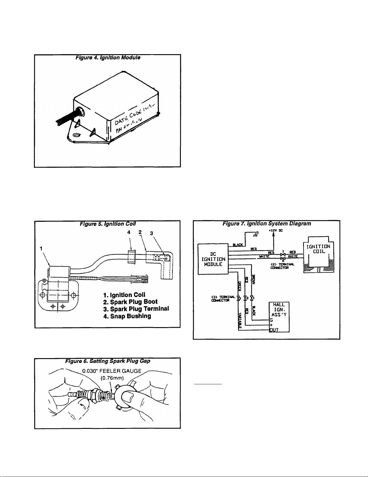
Section 6.4- ENGINE IGNITION SYSTEM
Ignition Module (Continued)
Ignition Coii
Primary Ignition voltage (12 VDC) Is delivered
from the Ignition Module to the Ignition Coll. The
Coil boosts the voltage and delivers the high volt
age to the engine Spark Plug.
Clean the Spark Plug and reset its gap to 0.030
inch (0.76mm) every 100 hours of operation. Clean
by scraping or wire brushinq and washing with
commerciaf solvent. DO NOT blast clean the spark
plug.
Summary of Operation
See Figure 6. As the generator’s permanent mag
net rotor turns, magnets in the Rotor hub’s Ignition
Cage rotate past an Ignition Sensor at fixeci inter
vals.
Battery voltage is delivered to an Ignition Module
during cranking and running, via Wire 14. From the
Ignition Module, battery voltag^e is also delivered to
the Ignition Sensor via the RED (+) lead. The Igni
tion Sensor acts as a "trigger" mechanism, causing
the Ignition Module to deliver its output to the
Ignition Coll at timed intervals. Current flows
through the primary coll of the Ignition Coil and
then collapses to Induce a high voltage Into the
Ignition Coil’s secondary coil. This high voltage
(about 25,000 volts) is delivered to the Spark Plug
to fire the spark plug gap.
Components encapsulated in the Ignition Mod
ule provide an automatic spark advance. At crank
ing speeds, ignition will occur at about 15'-18*
BTDC. At higher speeds. Ignition can occur up to
29* BTDC.
Spark Piug
The Spark Plug on GN-190 and GN-220 engines
is a Champion RC12YC (or equivalent).
Page 6.4-2
Ignition Timing
Ignition timing is fixed and non-adjustable.
Testing the System
GENERAL:
Solid state components Inside the Ignition Sen
sor, Ignition Module and Ignition Coil are not acces
sible and cannot be serviced. If any of these com
ponents is defective, the entire component must
be replaced. The system does not include an arma
ture and there Is no air gap to adjust, or breaker
points to adjust or replace.
Page 94

________________
Section 6.4- ENGINE IGNITION SYSTEM
TESTING FOR SPARK:
To test the Ignition system, a suitable spark tes
ter may be used. Such spark testers are commer
cially available. Test the system as follows:
1. Disconnect the high tension lead from the spark
plug.
2. Attach the spark plug
high tension lead to the
spark tester terminal.
3. Connect the spark tester
clamp to the engine cylin
der head.
4. Crank the engine rapidly.
Engine must be turning at
350 rpm or more. If spark
Jumps the tester gap, you
may assume the ignition
system is operating satis
factorily.
If sparking across the tester gap does-NOT
occur, go to XHECK POWER SUPPLY".
CHECKING ENGINE MISS:
To determine if an engine miss is Ignition related,
connect the spark tester In series with the spark
plug’s high tension lead and the spark plug. Then,
start the engine. If spark jumps the tester gap at
regular intervals but the engine miss continues, the
problem is In the spark plug or in the fuel system.
CHECK POWER SUPPLY:
When the engine is being cranked, battery volt
age should be available from the Engine Controller
circuit board to a 4-termlnal connector via Wire 14.
From the 4-termlnal connector, battery voltage
should be available to the Ignition Module via Wire
14 (RED wire). And battery voltage should be avail
able from the Ignition Module to the Ignition Sensor
via a RED wire. If this 12 VDC power supply is not
available, the ignition system will not function. To
check the power supply, proceed as follows using
a volt-ohm-milliammeter (VOM):
1. Gain access to the control panel interior.
2. In the panel, locate the 3-pin connector that
Interconnects the Ignition Module and the ignition
Sensor.
3. Press down on the connector lock tang and
disconnect the two connector halves.
NOTE: A single large black lead carries the three
leads from the Ignition Sensor to the 3-pln MALE
connector. The three leads from the Ignition Mod
ule (brown, green and red) attach to the 3-pln FE
MALE connector.
4. Set the VOM to a scale
that will allow battery volt
age to be read (about 12
volts DC).
5. Connect the meter test
leads across the center FE
MALE pin (RED wire) and
frame ground.
6. Hold the Start-Run-Stop
switch at "START". The
meter should read battery
voltage.
If battery voltage Is NOT indicated, go to Step 7.
If battery voltage IS Indicated, go to "CHECK IGNI
TION SENSOR^..
7. Now locate the 4-termi
nal connector in the panel.
Connect the VOM test
leads across the terminal
and frame ground. Crank
the engine and the VOM
should read battery volt
age.
a. If battery voltage is
indicated now but was
NOT Indicated In Step 6,
test Wire 14 (RED) be
tween the 4-terminal
connector and the Igni
tion Module. If wire is
bad, repair or replace as necessary.
b. If battery voltage Is NOT Indicated In Step 7,
test Wire 14 between the 4-terminal connector
and the Engine Controller circuit board. Repair
or replace as necessary.
CHECK IGNITION SENSOR:
1. In the 3-pln connector plug half from the Ignition
Module, locate FEMALE Pin 1 to which the BROWN
wire connects.
2. Connect a jumper wire from FEMALE Pin 1
(BROWN wire) to frame ground.
3. Connect the Spark Plug high tension lead to a
spark tester (Figure 8) and the spark tester clamp
to ground.
Page 6.4-3
Page 95

Section 6.4- ENGINE IGNITION SYSTEM
Testing the System (Continued)
CHECK IGNITION SENSOR (CONT’D);
4. Crank the engine and
observe the spark tester
for sparking.
IGNITION SENSOR" and under "TESTING IGNITION
COIL". If these components tested good, replace
the Ignition Module.
If sparking occurs with
the BROWN wire
grounded but did NOT
occur under "TESTING
FOR SPARK", the Ignition
Sensor is probabiy defec
tive and shouid be repiaced.
NOTE: The Ignition Sensor Is mounted to the
generator's Stator Adapter. To replace the Sensor,
disassembly of the generator and removal of the
Stator will be necessary.
If sparking does NOT occur with the BROWN wire
grounded and did NOT occur under "TESTING FOR
SPARK", either the Ignition Module or the Ignition
Coil is defective. Go to "TESTING IGNITION COIL".
TESTING IGNITION COIL:
The Ignition Coil is housed In the generator con
trol panel. To test the coil, proceed as follows:
1. Unplug the two halves of the 2-pin connector
plug from the Ignition Coil. The red and white wires
are the primary coil leads.
2. To read PRIMARY coil resistance:
a. Set a volt-ohm-milllammeter (VOM) to its "Rx1"
scale and zero the meter.
b. Connect the VOM test leads across the two
male pins of the 2-pin connector. Primary coil
resistance should be about 0.5 to 1.5 ohms.
3. To read SECONDARY coil resistance:
a. Set the VOM to its "Rxl0,000" or "Rx1K" scale
and zero the meter.
b. Unplug the high tension lead from the Spark
Plug.
c. Connect one VOM test lead to the white wire
connector pin.
d. Connect the other VOM test lead into the Spark
Plug lead rubber boot so it contacts the lead’s
metal terminal end. The VOM should read ap
proximately 16,000-17,000 ohms (16.0-17.0 k-
Ohms).
Figure 13. Testing Ignition Coll
Si
16,000-17,000 OHMS
Replace the Ignition Coil if defective. If the Ignition
Coll tested good, go to "TESTING IGNITION MOD
ULE".
TESTING IGNITION MODULE:
If a problem was indicated under "TESTING FOR
SPARK", you should have completed the tests
under "CHECK POWER SUPPLY", under "CHECK
Page 6.4-4
Page 96

Section 6.5- ENGINE PROTECTIVE DEVICES
The engine mounts an Oil Pressure Switch (LOP)
General
and an Oil Temperature Switch (НТО). These two
switches, In conjunction with the^gine Controller
circuit board, protect the engine against (a) low oil
pressure and (b) high oil temperature.
The engine protective circuit is shown In Rgure
1.
Oil Pressure Switch
DESCRIPTION:
The Oil Pressure Switch has normally-closed
contacts which are held open by engine oil
pressure during cranking and running. Should oil
pressure drop below approximately 5 psi, the
switch contacts will dose to complete the Wire 85
circuit to ground. Engine Controller circuit board
action will then de-energize the Wire 14 circuit and
the engine will shut down.
The Engine Controller circuit board provides a
time delay to allow oil pressure to build during
startup, to prevent premature shutdown.
NOTE: Early production NP40G units wore
equipped with a Low Oil Switch rated 10 psi (Part
No. ¿0108). Later production units are now
equipped with a Low Oii Switch rated 5 psi (Part No.
Т/бЕЛ. Units equipped with the 10psi Switch must
be retrofitted with the new 5 psi Switch (Part No.
77667). .
Figure 1. Engine Protective Circuit
BCCB - BtraiNB CONTROL CIRCUIT BORRO
НТО ■ HIOH Olb TSHP. SWITCH
LOP ■ LOW OIL PRBSSURB SWITCH
ECCB
НТО
T
O-p-o—< I
LOP
A. Schematic
’A ^
TESTING THE SWITCH:
Use a voit-ohm-milliammeter (VOM) to test the oil
pressure switch. Connect the VOM test leads
across the switch terminal and the switch body.
With the engine shut down, the meter should read
“continuity” (a very small resistance is
acceptable). With engine running, the meter should
read “infinity”.
Oil Temperature Switch
DESCRIPTION:
This thermostatic switch has normally-open
contacts. Should engine oil temperature exceed a
preset safe value (about 293^ F.), the switch
contacts will close. On closure of the Switch
contacts, the Wire 85 circuit will be connected to
frame ground. Engine shutdown will then occur.
NOTE: Eariy production NP40G units were
equipped with an Oil Temperature Switch rated
265^ F. That Oil Temperature Switch has been
replaced on later production units by the 293^ F.
Switch (Part No. 94090). Early units having the
26S^ F. Switch may be subject to overtemperature
shutdown and should be retrofitted with the new
293« F. Switch.
Page 6.5-1
Page 97

Section 6.5- ENGINE PROTECTIVE DEVICES
Oil Temperature Switch
(Continued)
NOTE: The CCG circuit board also has automatic
engine shutdown capability. The circuit board will
shut the engine down automatically on occurence
of (a) over-voltage, (bj under-voltage, (c) over
speed, (di zero current failure, (e) converter failure,
or (ef) micro-processor failure, see Section 1.2.
TESTING;
See Figure 3. Remove the switch and piace its
sensing tip into oii. Place a thermometer into the
oil. Connect the test leads of a VOM across the
switch terminals. The meter should read "Infinity''.
Heat the oil. When oil temperature reaches
approximately 287<-296a F. (142a-147a C.), the
meter should read "continuity" (a small resistance
Is acceptable).
NOTE: The above procedure yjplles to OII
Temperature Switch Part No. 94090, rated 293^ F.
(14S‘ C.). Some early production units were
equipped with a 265‘ F. switch which caused
premature high temperature shutdowns. The 265^
F. switch should be removed and replaced with the
Part No. 94090 switch.
Page 6.5-2
Revised- 02/07/95
Page 98
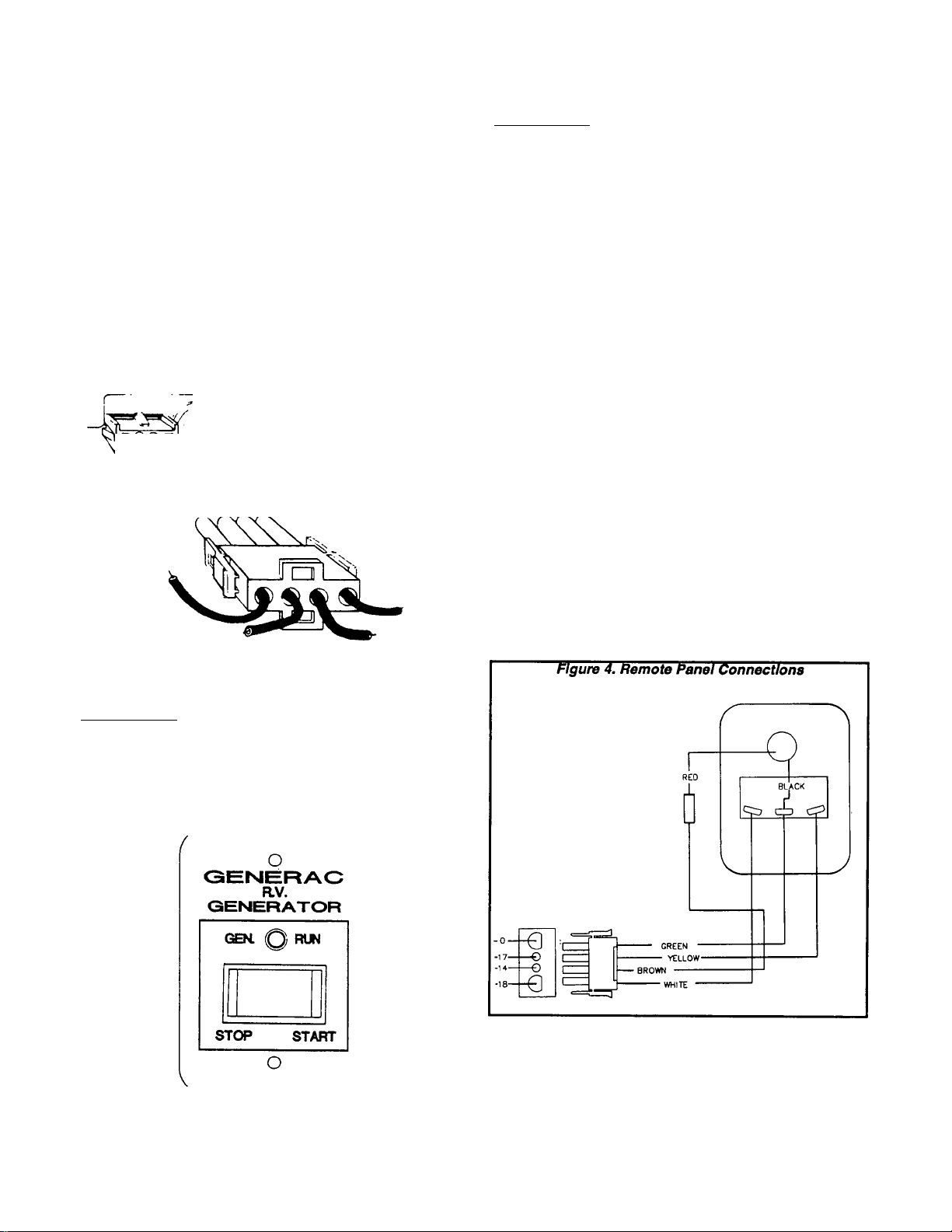
Section 6.6- OPTIONAL REMOTE PANEL
General
An optional remote-mounted Start-Stop panel is
available. This panel will permit the generator to be
started and stopped from some convenient remote
location In the recreational vehicle.
Remote Panel Cables
The generator Is equipped with a 4-pin receptacle
for connection of the remote panel. Cables are
available which mate with the receptacle and Inter
connect the generator with the remote panel.
□ Cable Model 9045 is a 10 foot long, 4-wlre cable.
□ Cable Model 9046 Is a 30 foot long, 4-wire cable.
Figure 1. Remote Panel Receptacle
WIRE #18
(STOP)
WIRE #0
(GROUND)
WIRE #14
(ENGINE RUN SIGNAL)
WIRE #17
(CRANK)
MODEL 9043:
The Model 9043 remote panel mounts a rocker
type Start-Run-Stop switch, a "GEN. RUN" lamp
and an hourmeter.
The "GEN. RUN" lamp will turn on when the
engine Is running. It is turned on by Wire 14 power.
The Hourmeter provides a continuous Indication
of oenerator operating hours in hours and tenths
of hours. It can be used in conjunction with the
required periodic maintenance on the unit.
Figure 3. Model 9043 Remote Panel
^GENERAC R.V. GENERATOR °
GEN.
STOP
o
RUN
START
O
TOTAL HOURS
o
o
Wiring Connections
wiring connections for the remote panel are
shown in Figure 4.
Description
MODEL 9042:
The Model 9042 remote panel mounts a rocker
type Start-Run-Stop switch and a "GEN. RUN" ad
visory lamp. The lamp Is turned on by Wire 14
current when the generator Is running.
Figure 2. Model 9042 Remote Panel
J
Page 6.6-1
Page 99

Section 6.6- OPTIONAL REMOTE PANEL
Page 6.6-2
Page 100

Part 7
TROUBLE
SHOOTING
COMPUTER
CONTROLLED
VARIABLE
SPEED RV
GENERATORS
Series NP-30G and NP-40G
SECTION
7.1
7.2
TITLE
GENERATOR & SPEED CONTROL
ENGINE DC CONTROL SYSTEM
 Loading...