

Page 1
Power Manager Integrated Controller
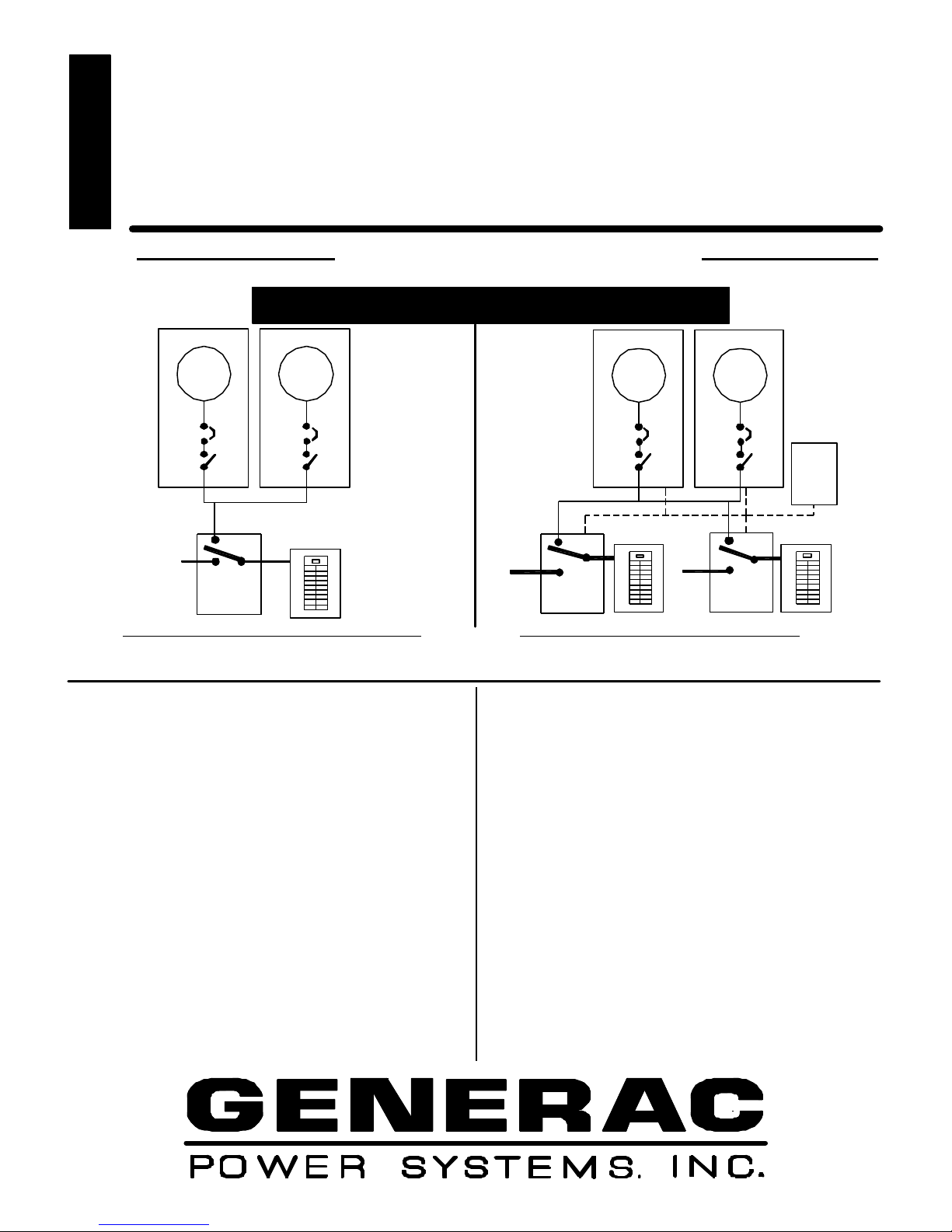
Layout
Power Manager System Controller Layout
FEATURES
Modular Power
System (MPS)
®
MPSG350
350 kW
Standby Power Rating Prime Power Rating
350 KW 60 Hz 280 KW 60 Hz
Powered with Generac’s 13.3 Natural Gas Engine
Diesel Generator
GEN
Circuit
Breaker
Contactor
UTILITY
Transfer Sw
Control
W/ Integral
Diesel Generator
GEN
Circuit
Breaker
Contactor
Distribution
Cab
n The Generac Modular Paralleling system utilizes
multiple small generators in a side by side parallel
arrangement to achieve a larger combined power
output.
n The proven 13.3 liter Generac generators can be
combined up to 10 units to provide from 300 kW to 1
megawatts of reliable power.
n Paralleling System Features. The paralleling function is
controlled by Generac’s field proven Power Manager
Control utilizing contractor switching technology
resulting in cost effective reliable paralleling. The MPS
control system provides automatic synchronization,
adjustable load sharing between generators, reverse
power protection and load shedding contacts.
n The optional cable interconnect cabinet is furnished with
bus bar and lugs to allow easy cabling between the
multiple gensets. Recommended for 3 or more gensets.
n The Generac “Power Manger Generator controller”
provides complete engine monitoring and control along
Diesel Generator
Diesel Generator
GEN GEN
UTILITY
Circuit
Breaker
Contactor
ATS
PMSC
Controller
Cabinet
Distribution
Cab
Circuit
Breaker
Contactor
Control Wires
Distribution
Cab
UTILITY
ATS
with alarm function and communication ability via a
RS232 with a modem link to Generac’s Genlink
software or Modbus control. A RS485 link is also
available.
n Flexibility. The Modular Power systems flexibility allows
for a wide variety of configurations, including single or
multiple automatic transfer switch arrangements roof
application where better weight distribution is required
and areas with specific height or depth limitations.
Since MPS gensets need not be located together, space
can be utilized wherever it is available. Smaller units
are also easier to transport and place on the jobsite.
n Redundancy. N+1 means greater reliability with MPS.
Backup power during scheduled maintenance.
Simplified service which reduces maintenance costs.
n Single source service response from Generac’s dealer
network provides parts and service support for the entire
unit. You are never on your own when you own a
Generac Power System
Page 2

APPLICATION
Ratings definitions
: See Generac Power Systems "
Power Rating Guidelines
" for specific definitions and application guidelines of the Standby Power, Prime Power and Continuous Power
& ENGINEERING DATA
MPSG 350
Modular Paralleling System
MPSG 350
System Description
The Generac control system consists of the Power Manager™
System Controller (PM-SC) or the Power Manager Integrated
Controller ()PM-IC) along with the Power Manager Generator
Controller (PM-GC). For single transfer switch installations with
the Generac Transfer Switch, the PM-IC is integral with the
transfer switch. For multiple transfer switch installations, the
PM-SC interfaces with the PM-GC to provide start/stop
commands based on utility power, proportional load sharing
and safe paralleling of each individual genset to the main bus or
transfer switch. Each individual genset has a built in heavy duty
switch to complete the paralleling operation. This switch and
it's control system replace the high cost switchgear and motor
operated circuit breakers associated with standard paralleling
systems.
System Components
Power Manager Generator Controller (PM-GC)
This control is installed on the generator set and monitors
all the engine parameters, including oil pressure, coolant
temperature, overspeed, kW and power factor.
It also controls the governor, voltage regulator and
the synchronizing connection to the bus.
Paralleling Switch
Installed in the generator set connection box
Heavy duty 3 pole solenoid actuated, mechanically
held, with emergency trip to off position
Rated at 400 amps and 1000 amps continuous
35,000 and 42,000 amps interrupting capacity
Built in arc suppression
Power Manager System Control (PM-SC)
Up to 3 primary transfer switches with up to 6 individual
steps for load sequencing, application or shedding with
assignable kW values for each step in addition to the
critical load ATS.
Unlimited number of secondary slave switches
The PM-SC is in an enclosure se parate from the transfer
switches.
Power Manager Integrated Control (PM-IC)
Integrated Control (IC) is installed in the same enclosure
as the single Generac Transfer Switch
Transfer Switch (PM- IC System )
1000 amp,1600 amp, 2600 amp (UL)3200 Amp (non UL)
For smaller switch ratings use the PM-SC control
42,000 AIC – 1000 Amp, 65,000 AIC – 1600 Amp,
85,000 AIC – 2600 - 3200 Amp
NEMA 12/3R enclosure
66"H x 36"W x 30" D – 1000 Amp
78"H x 48"W x 24" D – 1600 Amp
80” H x 48” W x 48” D – 2600 –3200 Amp
Wire access – top, side, bottom
NEMA 3R or 4X Optional
Wt. 1250 lbs. –1000-1600 Amp. 1850 lbs. 2600-3200 Amp
Connection Cabinet ( Optional )
NEMA 12/3R
80” H x 48” W x 48” D
Lug capacity –16 for Generator Controller (GC), 12 for
ATS. Each lug accepts (4) #4 to 750 MCM ( see Dwg. OD4482)
Floor mounting
Aluminum or Copper Wire compatible – 4500 amp bus
Sequence of Operations
1. The PM-IC or a transfer switch in the PM-SC configuration
detects a Utility failure and issues a start command. In the
PM-IC, the command goes direct to each PM- GC and with
multiple transfer switches the command goes to the PM-SC
which then issues a start command to the PM-GC's
2. Each Generator will start on its own.
3. The first generator that attains rated frequency and voltage
is connected to the main bus or transfer switch terminals via
the paralleling switch n the individual genset.
4. The remaining generators will synchronize with the bus and
the respective paralleling switch will close into the bus.
5. When all the gensets are paralleled to the main bus, the
System or Integrated Controller will signal the transfer switch
to transfer to the load. If multiple transfer switches are
installed, the PM-SC will connect these switches in 3
separate programmed steps.
6. If a NFPA requirement for 10 second start exists, the first
unit connects to the bus. This causes the controller in a
separate emergency transfer switch to immediately transfer
to the NFPA load.
7. If a single generator fails, load shed contacts are available to
disconnect selected non critical loads.
8. If load conditions are reduced, (night time operation)
selected generators can be programmed off line.
9. When Utility supply returns, the PM-SC or PM-IC will issue
commands to transfer loads back to the Utility. If then issues
commands to the individual PM-GC’s to disconnect from the
bus. Each PM-GC will operate its generator for the cooldown period and then issue a shutdown command.
Features: PM-IC & PM-SC
Programmable and viewable via Genlink
Provides up to 3 load shed contacts
Failsafe protective functions for reverse
`` Exercise controller
Ratings. Prime Power is not available at this time for MPS units.
power and synchronous paralleling control.
Backup battery
RS232 for Modem connection
RS485 Data Highway
System Configuration
Any KW configuration that equals the required load kW
can be used. The following page details a common
engine configuration and the most economical
configuration utilizing the MG150, MG200. But,
depending on load parameters any number of units up to
10 can be paralleled together.
Additional units and transfer switches can easily be added
at a later date.
Page 3

TOTAL SYSTEM PARAMETERS
1.0% for every 10 º F above
Output Voltage 60 Hz.
120/208
277/480
600 421
Combinations
350 kW 437.5 kVA
Rated Amps
1214
526
1 - 200 kW, 1 - 150 kW
MPSG350
Motor Starting
Inst Dip
kVA
15%
20%
25%
30%
35%
208 Volt Parallel Wye Network 480 Volt Series Wye Network
415
581
711
784
Alternator Parameters
Alternator Models
Sub Transient Reactance
Transient Reactance
Synchronous Reactance
Zero Sequence Reactance
Neg Sequence Reactance
Time Constant Seconds
Phase Sequence
Voltage Balance
Max Harmonics
Efficiency % @
60% Load
80% Load
100% Load
Engine Fuel Consumption @
% of Rated Load
25%
50%
75%
100%
Engine Cooling
Heat Rejection to Coolant( Full Load )
Coolant Capacity (total)
Inlet Cooling Air CFM
Maximum External Press Drop on Rad
Max air temp to radiator º F (derates apply)
Max ambient temperature º F (derates apply)
1,206,000 BTU/Hr. Total for the 2 units 1@ 700,000 btu/hr 1@ 506,000btu/Hr.
1-200 kW plus 1 - 150 kW 520 mm PMG Generac Alternators
0.16
0.23
3.1
0.07
0.18
0.0078
CBA
0.5%
3.50%
208 Volts 1.0 PF 480 Volts 1.0 PF
90.40% 90.70%
90.70% 91.10%
90.50%
Natural Gas 950 BTU /Cu.Ft
kW Cu Ft / Hr Therms/Hr.
87.5 11.49
175
262.5
350
15.4 gallons for the 2 units 77 Gallons per unit
34,400 for the 3 units 17,200 for each unit
0.5 inches H2O
1,209
2,329
3,429
4,467
350 kW
140 º F
120 º F
Combustion Air Requirements
Flow at Rated Power ( cfm)
1174 cfm Total. 618 cfm + 556 cfm
Exhaust
Exhaust Flow @ FL
Exhaust Temperature ( Average)
Exhaust Outlet per engine
Power Adjustments
Temperature 2% for every 10 º C above
Altitude 0.7% for every 100 m above
2.0% for every 1000 ft above
* Note: Temperatures will require necessary derates be applied. Unless otherwise noted, all data at 480 volt wye - 1.0 PF.
4017 CFM for the 2 units 2257 CFM + 1760 CFM
1128
1 @ 4.0" NPT
350 kW Standby
40 º C
104 º F
1066 Meters
3500 Feet
459
637
804
958
1098890
90.90%
22.12
32.58
42.44
Page 4

INTERCONNECTION DIAGRAM
GENERAC POWER SYSTEMS, INC. MPSG350
The PM-SC can control 3 transfer switches and any number of
the size and number of wires for the specific application.
1 - 200 kW 13.3 Liter
The PM-IC is part of the
Generac Transfer Switch
©
Typical Installations
Standard Enclosed units shown.
PMIC Power Manager Integrated Control PMSC Power Manager System Control
Generator Generator
powerpower
control
Power Manager
Integrated
Control
Transfer
Switch
control
A connection box for the power wires is an option.
+ 1 - 150 kW 13.3 Liter Gas
Powered Generator
Modules
Generator Generator
Gen Bus or
Connection
Cabinet (Opt)
ATS ATSATS
Control Wiring
Power Wiring
slave switches. The main connection box would be configured for
Electrical
Connections
AIR AND
EXHAUST
OUTLET
TOP SIDE
TOP VIEW
13.3 LITER
this area
Power
Manager
System
Control
(PM-SC)
Sound attenuated package adds an
additional 26" to the length.
Units can also be non-enclosed for
indoor installations.
AIR AND
EXHAUST
OUTLET
TOP SIDE
TOP VIEW
13.3 LITER
Electrical
Connections
this area
Minimum Clearance
between units
Area Space Requirements.
Units can be placed end to end, side by side or wherever room is available. The transfer switch or switches are generally placed
close to the main electric service. Consult State, Federal and Local codes for specific installation requirements.
Power Connections are in one area in the left rear quadrant of the genset.
All controls are through a single 2 wire RS485 connection that can be daisy chained between generators.
GENERAC
POWER SYSTEMS,INC.
P.O.BOX 8 WAUKESHA, WI. 53187
262-544-4811 FAX 262-544-0770
2003 GENERAC POWER SYSTEMS, INC. All rights reserved. All specifications subject to change without notice. Bulletin # 0168230SBY MW 06-28-03
DISTRIBUTED BY:
 Loading...