

Page 1
Owner’s Manual
Light Tower
MLT3060M • MLT3060K
000000
For technical assistance contact:
www.generacmobileproducts.com
Technical Support
1-800-926-9768
SAVE THIS MANUAL FOR FUTURE REFERENCE
Page 2
Use this page to record important information about your Light Tower
(000005)
WARNING
California Proposition 65. This product contains or
emits chemicals known to the state of California to
cause cancer, birth defects, and other reproductive
harm.
(000004)
WARNING
California Proposition 65. Engine exhaust and some
of its constituents are known to the state of California
to cause cancer, birth defects, and other reproductive
harm.
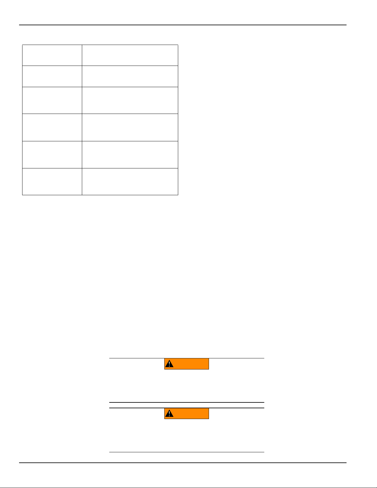
Record the information found on your unit data label on
Unit Model Number
Unit Serial Number
Engine Model
Number
Engine Serial
Number
Generator Model
Number
Generator Serial
Number
this page. See unit serial number location (Unit Serial
Number Locations). The label plate is affixed to the
inside partition, to the left of the control panel console.
Engine and generator serial numbers are located on
separate data plates affixed to the engine and generator
respectively.
When contacting a Generac Mobile Products Authorized
Dealer about parts and service, always supply the
complete model number and serial number of the unit.
Operation and Maintenance: Proper maintenance and
care of the Light Tower ensures a minimum number of
problems and keeps operating expenses at a minimum. It
is the operator’s responsibility to perform all safety
checks, to verify that all maintenance for safe operation is
performed promptly, and to have the equipment checked
periodically by a Generac Mobile Products Authorized
Dealer. Normal maintenance, service and replacement of
parts are the responsibility of the owner/operator and, as
such, are not considered defects in materials or
workmanship within the terms of the warranty. Individual
operating habits and usage may contribute to the need
for additional maintenance or service.
ii Owner’s Manual for MLT3060M-K Light Tower
Page 3

Table of Contents
Section 1: Safety Rules & General
Information
Introduction ..........................................................1
Read This Manual Thoroughly ....................................1
How to Obtain Service .................................................1
Safety Rules .........................................................1
General Hazards ..................................................2
Explosion and Fire Hazards ................................2
Trailer Hazards .....................................................2
Electrical Hazards ................................................3
Battery Hazards ...................................................3
Fuel Hazards ........................................................4
Engine Safety .......................................................4
Operating Safety ..................................................4
Positioning the Unit .....................................................4
Starting the Unit ...........................................................4
Raising and Lowering the Mast ...................................5
Service Safety ......................................................5
Towing Safety ......................................................6
Hitch and Coupling ......................................................6
Running Lights ............................................................6
Wheels and Tires ........................................................6
Safe Towing Techniques .............................................6
Reporting Trailer Safety Defects ........................6
Safety and Operating Decals ..............................7
Prestart Checklist .............................................. 26
Raising the Mast ................................................ 26
Starting the Unit ................................................ 27
Preparing for Start-Up (with PowerZone
Controller, If Equipped) .................................... 28
Select AUTO or MANUAL Mode ............................... 28
Manually Starting the Unit ................................ 28
Light Operation .................................................. 29
Light Operation (With PowerZone Controller, If
Equipped) ........................................................... 29
Engine Derating ................................................. 29
Wet Stacking ...................................................... 30
Customer Convenience Outlets ....................... 30
Shutting Down the Unit ..................................... 30
Shutting Down the Unit (with PowerZone
Controller, If Equipped) .................................... 30
Automatic Shutdown .................................................30
Lower Radiator Hose Heater (If Equipped) ..... 30
Spark Arrester (If Equipped) ............................ 31
Lowering the Mast ............................................. 31
Removing the Lights for Transportation ......... 31
Towing the Unit .................................................31
Tying the Unit Down .......................................... 32
Lifting the Unit ................................................... 32
Section 2: General Information
Specifications ....................................................13
Unit Dimensions ................................................14
Unit Serial Number Locations ..........................15
Component Locations .......................................16
Control Panel .....................................................17
Control Panel Features and Functions ......................18
PowerZone–DLA (If Equipped) .........................19
Controller Features and Functions ............................19
Operator Screens ......................................................20
Section 4: Maintenance
Emissions Information ...................................... 33
Daily Walk-Around Inspection ......................... 33
General Maintenance ........................................ 33
Preparing for Service .................................................33
Cleaning the Unit ....................................................... 33
Inspecting the Unit .....................................................33
Basic Maintenance Schedule ........................... 34
Resetting the Maintenance Alarms
(If Equipped) ......................................................37
Winch Use, Operation and Maintenance ......... 37
Section 3: Operation
Light Tower Setup .............................................25
Owner’s Manual for MLT3060M-K Light Tower iii
Prior to Use ............................................................... 37
Operation ...................................................................37
Maintenance ..............................................................37
Page 4

Table of Contents
Jack Maintenance ..............................................38
Trailer Wheel Bearings ......................................38
Section 5: Troubleshooting
General Troubleshooting ..................................39
Troubleshooting the Lights ..............................40
Section 6: Wiring Diagrams
Mast Junction Box Wiring and Light
Connections .......................................................41
AC Wiring ...........................................................42
DC Wiring—MLT3060M .....................................43
DC Wiring—MLT3060K ...................................... 44
DC Wiring for Optional Equipment ..................45
Trailer Wiring ......................................................46
iv Owner’s Manual for MLT3060M-K Light Tower
Page 5
Safety Rules & General Information
(000100a)
WARNING
Consult Manual. Read and understand manual
completely before using product. Failure to
completely understand manual and product
could result in death or serious injury.
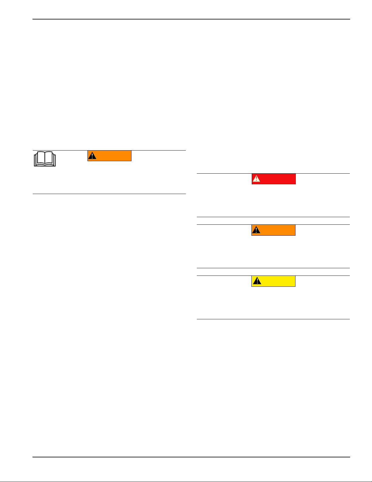
(000001)
DANGER
Indicates a hazardous situation which, if not avoided,
will result in death or serious injury.
(000002)
WARNING
Indicates a hazardous situation which, if not avoided,
could result in death or serious injury.
(000003)
CAUTION
Indicates a hazardous situation which, if not avoided,
could result in minor or moderate injury.
Section 1: Safety Rules & General Information
Introduction
Thank you for purchasing a Generac Mobile Products LLC
product. This unit has been designed to provide high
performance, efficient operation, and years of use when
maintained properly.
The information in this manual is accurate based on
products produced at the time of publication. The
manufacturer reserves the right to make technical updates,
corrections, and product revisions at any time without
notice.
Read This Manual Thoroughly
If any section of the manual is not understood, contact your
nearest Generac Mobile Products Authorized Dealer, or
contact Generac Mobile Products Technical Service at
1-800-926-9768 or
with any questions or concerns.
www.generacmobileproducts.com
Safety Rules
The manufacturer cannot anticipate every possible
circumstance that might involve a hazard. The warnings in
this manual, and on tags and decals affixed to the unit are,
therefore, not all inclusive. If using a procedure, work
method or operating technique that the manufacturer does
not specifically recommend, verify that it is safe for others.
Also make sure the procedure, work method or operating
technique utilized does not render the equipment unsafe.
Throughout this publication, and on tags and decals affixed
to the unit, DANGER, WARNING, CAUTION and NOTE
blocks are used to alert personnel to special instructions
about a particular operation that may be hazardous if
performed incorrectly or carelessly. Observe them
carefully. Their definitions are as follows:
The owner is responsible for proper maintenance and safe
use of the equipment. Comply with regulations the
Occupational Safety and Health Administration (OSHA)
has established, or with equivalent standards. Also, verify
that the unit is applied, used, and maintained in accordance
with the manufacturer's instructions and recommendations.
Do nothing that might alter safe application/usage and
render the unit in noncompliance with the aforementioned
codes, standards, laws, and regulations
Save these instructions for future reference. This manual
contains important instructions for the unit that should be
followed during setup, operation and maintenance of the
unit and battery. ALWAYS supply this manual to any
individual that will use this machine.
.
How to Obtain Service
When the unit requires servicing or repairs, contact an
Generac Mobile Products Authorized Dealer for assistance.
Service technicians are factory-trained and are capable of
handling all service needs. For assistance locating a dealer,
go to
www.generacmobleproducts.com/parts-service/
find-service
Products Authorized Dealer about parts and service,
always supply the complete model number and serial
number of the unit as given on its data decal located on
the unit. Record the model number and serial numbers in
the spaces provided on the inside front cover of this
manual.
Owner’s Manual for MLT3060M-K Light Tower 1
.
When contacting an Generac Mobile
NOTE: Notes contain additional information important to
a procedure and will be found within the regular text of
this manual.
These safety alerts cannot eliminate the hazards that they
indicate. Common sense and strict compliance with the
special instructions while performing the action or service
are essential to preventing accidents.
Page 6

Safety Rules & General Information
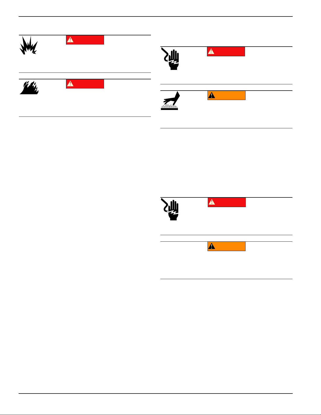
Asphyxiation. Running engines produce
carbon monoxide, a colorless, odorless,
poisonous gas. Carbon monoxide, if not
avoided, will result in death or serious injury.
(000103)
DANGER
(000107)
WARNING
Hearing Loss. Hearing protection is
recommended when using this machine.
Failure to wear hearing protection could
result in permanant hearing loss.
(000111)
WARNING
Moving Parts. Keep clothing, hair, and
appendages away from moving parts. Failure
to do so could result in death or serious injury.
(000108)
WARNING
Hot Surfaces. When operating machine, do not
touch hot surfaces. Keep machine away from
combustibles during use. Hot surfaces could
result in severe burns or fire.
(000182)
WARNING
Only qualified service personnel may install, operate,
and maintain this equipment. Failure to follow proper
installation requirements could result in death, serious
injury, and damage to equipment or property.
WARNING
Risk of injury. Do not operate or service this machine
if not fully alert. Fatigue can impair the ability to service
this equipment and could result in death or serious
injury.
(000215)
(000139)
WARNING
Risk of burns. Allow engine to cool before
draining oil or coolant. Failure to do so could
result in death or serious injury.
(000105)
DANGER
Explosion and Fire. Fuel and vapors are
extremely flammable and explosive. Add fuel
in a well ventilated area. Keep fire and spark
away. Failure to do so will result in death
or serious injury.
(000147)
WARNING
Risk of Fire. Unit must be positioned in a
manner that prevents combustible material
accumulation underneath. Failure to do so
could result in death or serious injury.
(000110)
WARNING
Risk of Fire. Hot surfaces could ignite
combustibles, resulting in fire. Fire could
result in death or serious injury.
WARNING
Trailer must be securely coupled to the hitch and the
chains correctly attached. Uncoupled or unchained
towing could result in death or serious injury.
(000233)
WARNING
Do not operate this unit while transporting. Doing so
could result in death or serious injury.
(000231)
(000234a)
WARNING
Crushing hazard. Verify unit is properly secured and
on level ground. An unsecured unit can suddenly roll
or move, causing death or serious injury.
WARNING
Property or Equipment Damage. Tighten wheel lug
nuts after first 50 miles to factory specifications.
Failure to do so could result in death, serious injury,
property or equipment damage.
(000235)
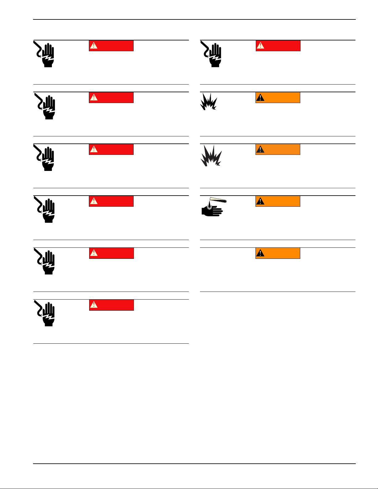
General Hazards Explosion and Fire Hazards
Trailer Hazards
2 Owner’s Manual for MLT3060M-K Light Tower
Page 7
Safety Rules & General Information
(000145)
DANGER
Electrocution. In the event of electrical accident,
immediately shut power OFF. Use non-conductive
implements to free victim from live conductor. Apply
first aid and get medical help. Failure to do so will
result in death or serious injury.
(000104)
DANGER
Electrocution. Water contact with a power
source, if not avoided, will result in death
or serious injury.
(000144)
DANGER
Electrocution. Contact with bare wires,
terminals, and connections while generator
is running will result in death or serious injury.
(000152)
DANGER
Electrocution. Verify electrical system is
properly grounded before applying power.
Failure to do so will result in death or serious
injury.
(000188)
DANGER
Electrocution. Do not wear jewelry while
working on this equipment. Doing so will
result in death or serious injury.
DANGER
Electrocution. DO NOT use the unit if
electrical cord is cut or worn through. Doing
so will result in death or serious injury.
(000263a)
(000188)
DANGER
Electrocution. Do not wear jewelry while
working on this equipment. Doing so will
result in death or serious injury.
(000137a)
WARNING
Explosion. Batteries emit explosive gases while charging.
Keep fire and spark away. Wear protective gear when
working with batteries. Failure to do so could result in
death or serious injury.
(000162)
WARNING
Explosion. Do not dispose of batteries in a fire. Batteries
are explosive. Electrolyte solution can cause burns and
blindness. If electrolyte contacts skin or eyes, flush with water
and seek immediate medical attention.
(000163a)
WARNING
Risk of burn. Do not open or mutilate batteries.
Batteries contain electrolyte solution which can
cause burns and blindness. If electrolyte contacts
skin or eyes, flush with water and seek immediate
medical attention.
WARNING
Environmental Hazard. Always recycle batteries at an
official recycling center in accordance with all local
laws and regulations. Failure to do so could result in
environmental damage, death or serious injury.
(000228)
Electrical Hazards Battery Hazards
Owner’s Manual for MLT3060M-K Light Tower 3
Always recycle batteries in accordance with local laws and
regulations. Contact your local solid waste collection site
or recycling facility to obtain information on local recycling
processes. For more information on battery recycling, visit
the Battery Council International website at: http://
batterycouncil.org
Page 8
Safety Rules & General Information
(000192)
DANGER
Explosion and fire.Fuel and vapors are extremely
flammable and explosive. No leakage of fuel is
permitted. Keep fire and spark away. Failure to do
so will result in death or serious injury.
(000174)
DANGER
Risk of fire. Allow fuel spills to completely dry
before starting engine. Failure to do so will
result in death or serious injury.
(000260a)
High Voltage. Verify area above unit is clear
of overhead wires and obstructions. Contact
with high-voltage power lines will result in
death or serious injury.
DANGER
(000277)
WARNING
Burn hazard. Never operate lights with a
damaged or missing lens cover. Lamps are
hot and pressurized while in use. Unprotected
lamps can shatter, causing severe injury.
DANGER
Electrocution. DO NOT use the unit if
electrical cord is cut or worn through. Doing
so will result in death or serious injury.
(000263a)
CAUTION
(000291)
Equipment damage. Do not attempt to start or operate
a unit in need of repair or scheduled maintenance.
Doing so could result in serious injury, death, or
equipment failure or damage.
WARNING
Fuel Hazards
• DO NOT fill fuel tank near an open flame, while
smoking, or while engine is running. DO NOT fill
tank in an enclosed area with poor ventilation.
• DO NOT operate with the fuel tank cap loose or
missing.
Engine Safety
Internal combustion engines present special hazards
during operation and fueling. Failure to follow the safety
guidelines described below could result in severe injury or
death. Read and follow all safety alerts described in the
engine operator's manual. A copy of this manual was
supplied with the unit when it was shipped from the factory.
Operating Safety
Positioning the Unit
The area immediately surrounding the unit should
•
be dry, clean, and free of debris.
• Position and operate the unit on a firm, level
surface.
• If the unit is equipped with a frame grounding stud,
follow the National Electrical Code (NEC), state,
and local regulations when connecting.
Starting the Unit
• DO NOT run engine indoors or in an area with poor
ventilation. Make sure engine exhaust cannot seep
into closed rooms or ventilation equipment.
• DO NOT clean air filter with gasoline or other types
of low flash point solvents.
• DO NOT operate the unit without a functional
exhaust system.
• Shut the engine down if any of the following
conditions exist during operation:
• Abnormal change in engine speed.
• Loss of electrical output.
• Equipment connected to the unit overheats.
• Sparking occurs.
• Engine misfires or there is excessive engine/
generator vibration.
• Protective covers are loose or missing.
• Ambient air temperature is above 120°F (49°C).
4 Owner’s Manual for MLT3060M-K Light Tower
Page 9
Safety Rules & General Information
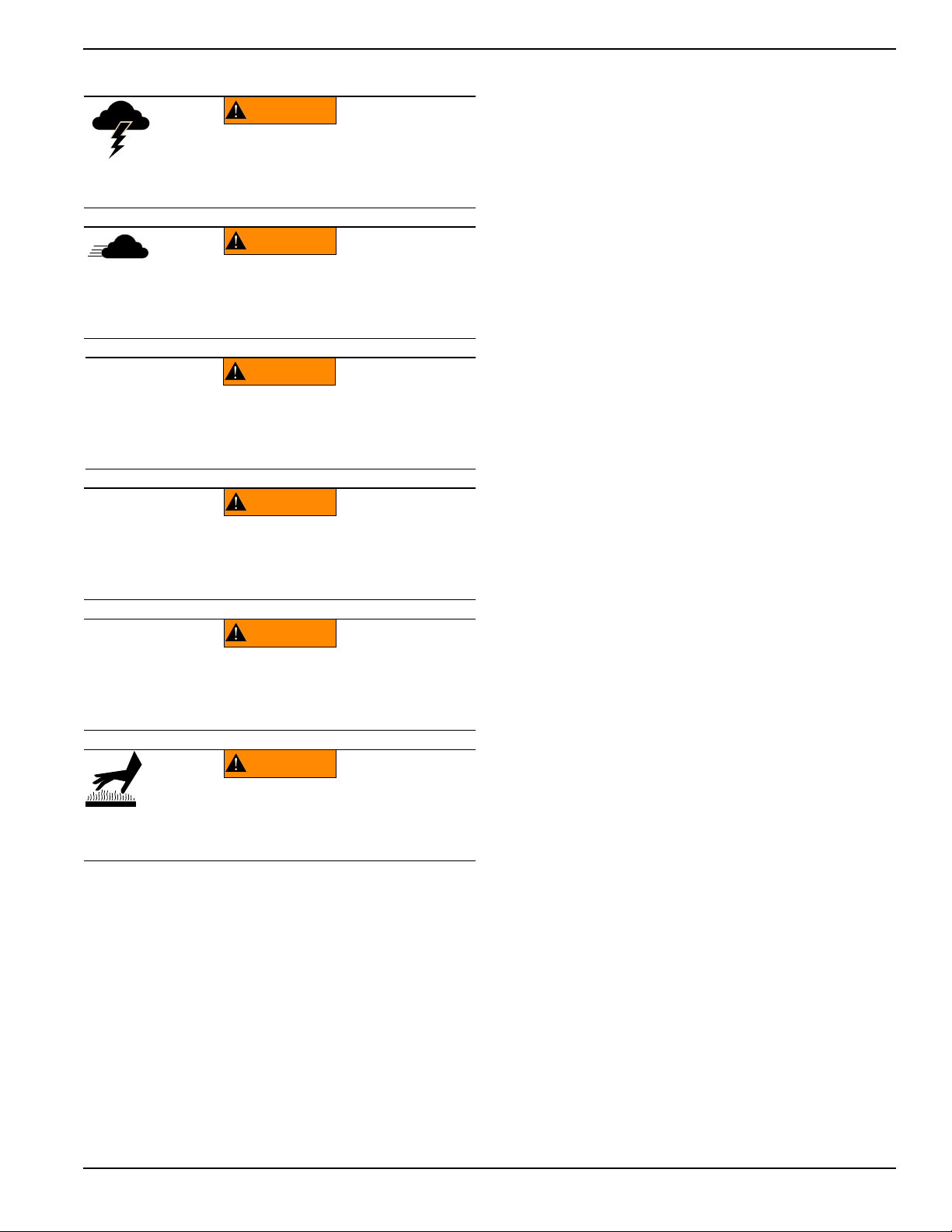
WARNING
Electrocution. Do not set up or operate
this unit if severe weather is expected.
Lightning strikes can kill or cause severe injury
even if you are not touching the unit.
(000296)
WARNING
(000297)
> 60 mph> 60 mph
Do not set up the unit if high winds
are expected. High winds can cause the
unit to tip or fall, causing severe injury
or machine damage.
(000279)
Personal injury or equipment damage. Do not raise
or lower the mast while the unit is operating.
Doing so can break the lenses and cause the
lamps to shatter.
WARNING
WARNING
Personal Injury. Stop immediately if the mast hangs
up or the winch cable develops slack. Excess slack
could cause the mast to collapse, resulting in personal
injury or equipment damage.
(000265)
WARNING
Tipping hazard. Extend the outriggers and level the unit
before raising the mast. Keep the outriggers extended
while the mast is up. Failure to do so could cause the unit
to tip and fall and could result in death or serious injury.
(000266)
(000278)
WARNING
Burn hazard. Lamps become extremely hot
while in use. Allow 10–15 minutes for cooling
before handling or lowering mast. Touching a
hot lens or fixture can cause severe burns.
Raising and Lowering the Mast
Service Safety
This unit uses high voltage circuits capable of causing
serious injury or death. Only a qualified and licensed
electrician should troubleshoot or repair problems
occurring in this equipment.
•
Before servicing the unit, verify the Control Power
switch and circuit breakers are in the OFF (O)
position, and the negative (-) terminal on the battery
is disconnected.
service (oil/filter changes, cleaning, etc.) unless all
electrical components are shut down.
•
ALWAYS
unit in damp conditions. Do not service the unit if your
skin or clothing is wet. Do not allow water to collect
around the base of the unit.
•
DO NOT
power washers, or steam cleaners. Water may
collect in the unit, causing damage to electrical parts.
•
Replace all missing and hard to read decals. Decals
provide important operating instructions and warn of
dangers and hazards.
•
Wear heavy leather gloves when handling winch
cables. Never let cables slip through bare hands.
•
Only use mild soap and water to clean the lens covers.
Other chemicals may damage the lens covers.
use extreme caution when servicing this
wash the unit with high pressure hoses,
• Make sure slings, chains, hooks, ramps, jacks and
other types of lifting devices are attached securely
and have enough weight-bearing capacity to lift or
hold the equipment safely. Always remain aware of
the position of other people around you when lifting
the equipment.
DO NOT
perform even routine
Keep area around the unit clear of people while
•
raising and lowering the mast.
• ALWAYS lower the mast when not in use.
• The tower extends up to 30 ft (9.14 m). Make sure
area above trailer is open and clear of overhead
wires and obstructions.
• If for any reason any part of mast hangs up or
winch cable develops slack while raising or
lowering tower, STOP immediately! Contact a
Generac Mobile Products Authorized Service
Dealer.
• NEVER remove safety pin or pull mast locking pin
while tower is up.
Owner’s Manual for MLT3060M-K Light Tower 5
Page 10

Safety Rules & General Information
Towing Safety
Towing a trailer requires care. Both the trailer and vehicle
must be in good condition and securely fastened to each
other to reduce the possibility of an accident. Some states
require that large trailers be registered and licensed.
Contact your local Department of Transportation office to
check on license requirements for your particular unit.
Hitch and Coupling
•
Verify the hitch and coupling on the towing vehicle
are rated equal to, or greater than, the trailer's
Gross Vehicle Weight Rating (GVWR).
• Verify the trailer hitch and the coupling are
compatible. Make sure the coupling is securely
fastened to the vehicle.
• DO NOT tow trailer using defective parts. Inspect
the hitch and coupling for wear or damage.
• Connect safety chains in a crossing pattern under
the tongue.
• Before towing the trailer, verify the weight of the
trailer is equal across all tires. On trailers with
adjustable height hitches, adjust the angle of the
trailer tongue to keep the trailer as level as
possible.
Reporting Trailer Safety Defects
If you believe your trailer has a defect which could cause
a crash or could cause injury or death, you should
immediately inform the National Highway Traffic Safety
Administration (NHTSA) in addition to notifying Generac
Mobile Products LLC.
If NHTSA receives similar complaints, it may open an
investigation; and if it finds that a safety defect exists in a
group of vehicles, it may order a recall and remedy
campaign. However, NHTSA cannot become involved in
an individual problem between you, your dealer, or
Generac Mobile Products LLC.
To contact NHTSA, you may either call the Auto Safety
Hotline toll-free at 1-888-327-4236 (TTY:1-800-424-9153),
go to http://www.safercar.gov; or write to:
Administrator
NHTSA
1200 New Jersey Avenue S.E.
Washington, DC 20590
You can also obtain other information about motor vehicle
safety from http://www.safercar.gov.
Running Lights
Verify directional and brake lights on the trailer are
connected and working properly
Wheels and Tires
•
Check trailer tires for wear and proper inflation.
• Verify wheel lug nuts are present and tightened to
the specified torque.
Safe Towing Techniques
•
Practice turning, stopping and backing up in an
area away from heavy traffic prior to transporting
the unit.
• Maximum recommended speed for highway towing
is 45 mph (72 km/h). Recommended off-road
towing speed is 10 mph (16 km/h) or less,
depending on terrain.
• When towing, maintain extra space between
vehicles and avoid soft shoulders, curbs and
sudden lane changes.
6 Owner’s Manual for MLT3060M-K Light Tower
Page 11
Safety Rules & General Information
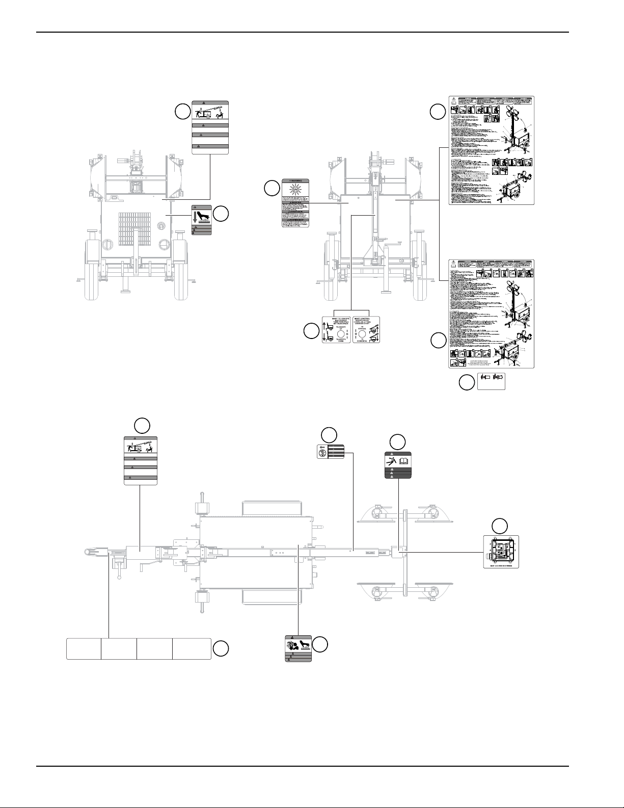
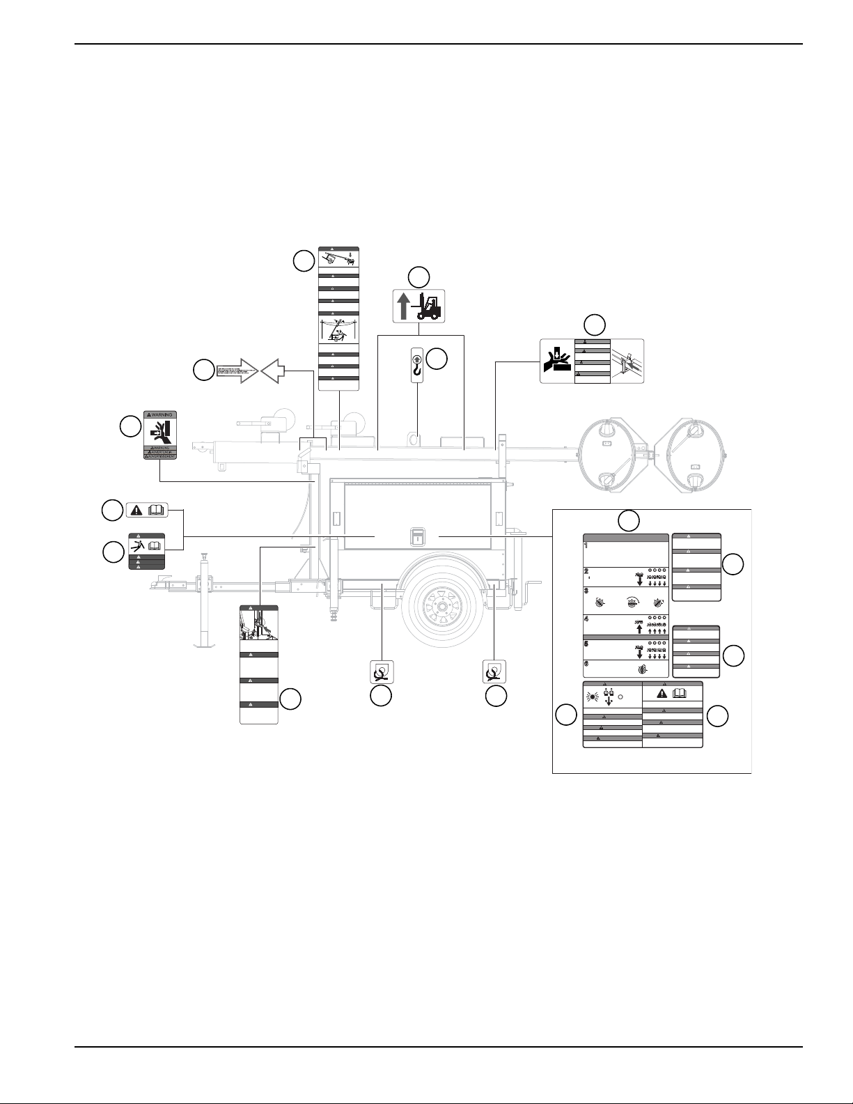
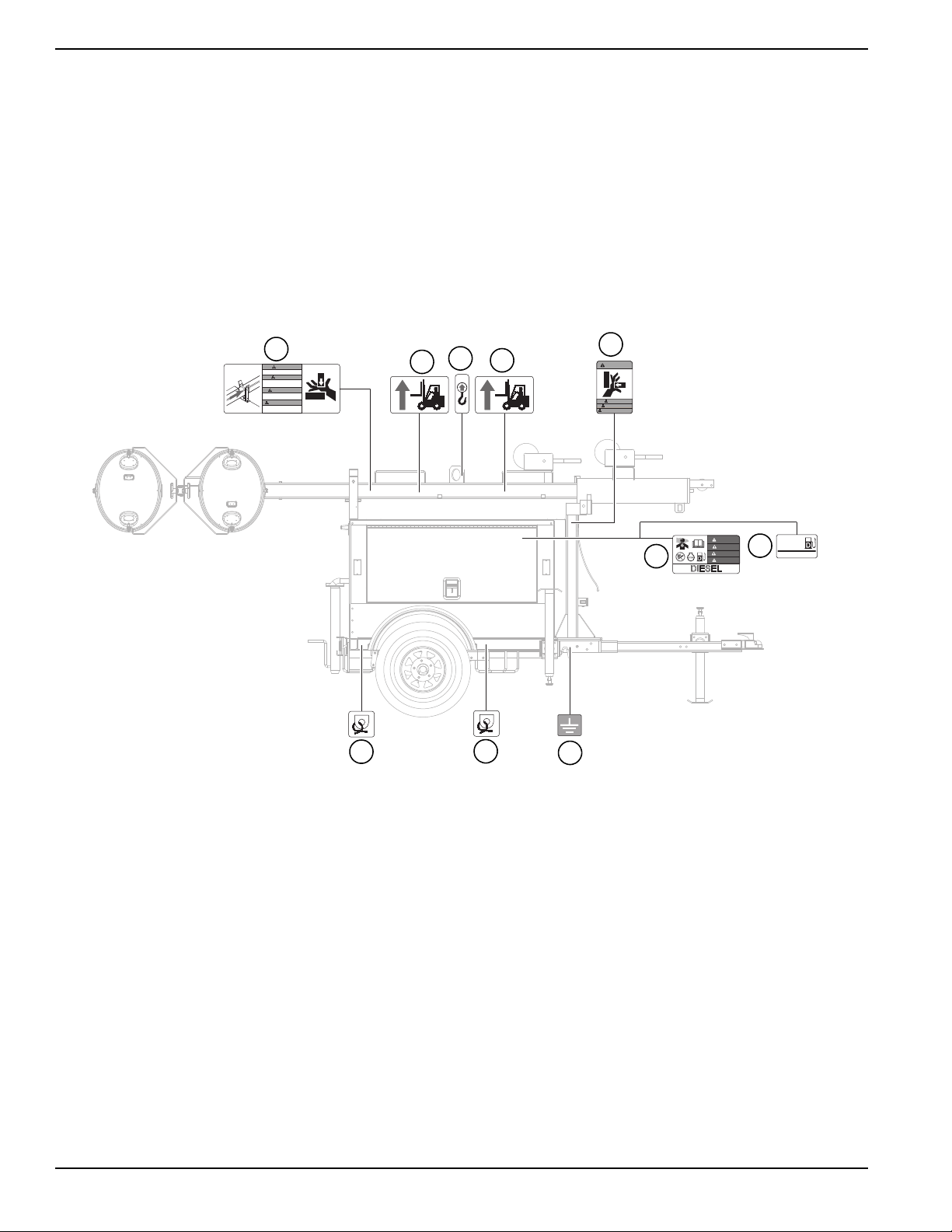
Safety and Operating Decals
See Figure 1-1 through Figure 1-4. This unit features
numerous safety and operating decals. These decals
provide important operating instructions and warn of
dangers and hazards. The following diagrams illustrate
decal locations and descriptions.
Replace any missing or hard-to-read decals and use care
when washing or cleaning the unit. Decal part numbers
can be found in the parts manual at
www.generacmobileproducts.com.
ID Description
1 Warning–Stand Clear When Mast is Being Tilted
2 Warning–Hot Surface
3 Warning–Ultraviolet Radiation
4 Instruction–Raise Mast Manual Winch
5 Instruction–Raise Mast Electric Winch
6 Instruction–Mast Control Electric Winch
7 Danger–Do Not Remove
27 Danger–Diesel Fuel, Asphyxiation, No Open Flame
28 Ultra Low Sulfur Fuel Only
29 Grounding Stud
30 Warning–Fire and Explosion
31 Warning–Moving Parts
32 Warning–Hot Surface, Moving Parts
8 Danger–Electrocution
9 Instruction–Keep Tension on Cables
10 Mast Junction Box Wiring
11 Warning–Hot Surface, Fire and Explosion
12 Instruction–Towing Instructions
13 Instruction–Align Before Tilting Mast Down
Danger–Lower Mast Before Tilting, Do Not Position
14
Light Tower Under Power Lines
15 Forklift Pockets
16 Single Point Lift Location
17 Warning–Secure Mast Before Lifting or Towing
18 Instruction–Engine Operation
Danger–High Winds and Storms, Overhead
19
Obstructions
20 Danger–Do Not Move Unit With Tower Up
21 Warning–Read Manual Before Operating Unit
Warning–Verify Circuit Breaker is OFF Before
22
Starting Unit
23 Tie-Down Point
24 Secure Mast
25 Consult Manual
26 Warning–Pinch Point
Owner’s Manual for MLT3060M-K Light Tower 7
Page 12
Safety Rules & General Information
WARNING
WARNUNG
ADVERTENCIA
ADVERTISSEMENT
STAND CLEAR OF FRONT AND REAR OF MACHINE
WHEN MAST IS BEING TILTED UP OR DOWN.
AUFENTHALT INVORDERER ODER HINTERER UMGEBUNG
DES GERÄTES VERMEIDEN WÄHREND MAST HOCH ODER
NIEDER GESCHWENKT WIRD.
MANTENGASE ALEJADO DE LA PARTE DELANTERA O
TRASERA DE LA MAQUINA MIENTRAS QUE SE ESTA
PROCEDIENDO A LEVANTAR EL MASTIL A LA POSICION
VERTICAL O VOLCARLO A LA POSICION HORIZONTAL.
TENEZ-VOUS A DISTANCE DE L’AVANT ET DE
L’ARRIERE DE LA MACHINE PENDANT LE BASCULEMENT
DU MAT DANS UN SENS OU DANS L’AUTRE.
ADVERTENCIA
WARNUNG
ADVERTISSEMENT
WARNING
ALWAYS KEEP TENSION ON CABLES! SLACK MAY CAUSE CABLE
DAMAGE AND EXCESSIVE WEAR!
¡CSIEMPRE TENSIÓN DE LA SUBSISTENCIA EN LOS CABLES! ¡CCAUSA
FLOJA CABLEDAMAGE DE MAYO Y DESGASTE EXCESIVO!
TOUJOURS TENSION DE SUBSISTANCE SUR DES CÂBLES !
CAUSE LÂCHE CABLEDAMAGE DE MAI ET USAGE EXCESSIF !
IMMER UNTERHALT-SPANNUNG AUF KABELN! LOCKERE MAI URSACHE
CABLEDAMAGE UND ÜBERMÄSSIGE ABNUTZUNG!
Located on
bottom side
of mast
1. READ OPERATOR'S MANUAL.
2. USE HITCH RATER FOR TRAILER'S
"GROSS VEHICLE WEIGHT RATING".
3. SECURELY ATTACH TRAILER TO TOW VEHICLE.
4. ATTACH SAFETY CHAINS USING A CROSS
PATTERN.
5. ATTACH BREAKDOWN CHAIN TO VEHICLE.
6. CHECK TRAILER LIGHTS.
TOWING INSTRUCTIONS INSTRUCCIONES DE REMOLQUE
1. LEA EL MANUAL DEL OPERARIO.
2. UTILICE UN ACOPLE CORRECTAMENTE
CLASIFICADO PARA LA "CLASE DE PESO
BRUTO" DEL VEHICULO DE REMOLQUE
3. ASEGURESE DE ACOPLAR CORRECTAMENTE EL
REMOLQUE AL VEHICULO DE REMOLQUE.
4. FIJE EN CRUZ LAS CADENAS DE SEGURIDAD.
5. FIJE EN EL VEHICULO DE REMOLQUE
LA CADENA DE DESPRENDIMIENTO.
6. CONTROLE LAS LUCES DEL REMOLQUE.
ABSCHLEPPINSTRUKTIONEN
1. LIRE LA NOTICE D’EMPLOI.
2. UTILISER UN CROCHET D’ATTELAGE CONFORME
AU DEBIT NOMINAL DU POIDS BRUT DE
VEHICULE DU VEHICULE TRACTEUR.
3. ATTACHER LA REMORQUE FERMEMENT AU
VEHICULE TRACTEUR.
4. ATTACHER LES CHAINES DE SURETE EN
UTILISANT UNE METHODE CROISEE.
5. ATTACHER LA CHAINE DE REMORQUAGE AU VEHICULE.
6. VERIFIER LES LAMPES DE LA REMORQUE.
INSTRUCTIONS DE REMORQUAGE
1. BETRIEBSVORSCHRIFT LESEN.
2. ANHÄNGEVORRICHTUNG VERWENDEN,
DIE DER GESAMTBETRIEBSGEWICHTSKLASSE
ENTSPRICHT .
3. ANHÄNGER SICHER AM ZUGFAHRZEUG
BEFESTIGEN.
4. SICHERHEITSKETTEN KREUZWEISE ANBRINGEN.
5. ABREISSKETTE AM FAHRZEUG ANBRINGEN.
6. ANHÄNGERLEUCHTEN PRÜFEN.
N'ENLEVEZ PAS !
GEFAHR
PELIGRO
DANGER
DANGER
DO NOT REMOVE!
ENTFERNEN SIE NICHT!
NO QUITE!
DANGER
GEFAHR
PELIGRO
DANGER
WARNUNG
ADVERTISSEMENT
ADVERTENCIA
WARNING
WARNING
WARNUNG
ADVERTENCIA
ADVERTISSEMENT
STAND CLEAR OF FRONT AND REAR OF MACHINE
WHEN MAST IS BEING TILTED UP OR DOWN.
AUFENTHALT INVORDERER ODER HINTERER UMGEBUNG
DES GERÄTES VERMEIDEN WÄHREND MAST HOCH ODER
NIEDER GESCHWENKT WIRD.
MANTENGASE ALEJADO DE LA PARTE DELANTERA O
TRASERA DE LA MAQUINA MIENTRAS QUE SE ESTA
PROCEDIENDO A LEVANTAR EL MASTIL A LA POSICION
VERTICAL O VOLCARLO A LA POSICION HORIZONTAL.
TENEZ-VOUS A DISTANCE DE L’AVANT ET DE
L’ARRIERE DE LA MACHINE PENDANT LE BASCULEMENT
DU MAT DANS UN SENS OU DANS L’AUTRE.
1
2
3
4
5
6
1
7
8
9
10
11
12
8 Owner’s Manual for MLT3060M-K Light Tower
Figure 1-1. Decals - Front, Rear and Top
Page 13
Safety Rules & General Information
A NON-SECURED, FALLING MAST WILL
CAUSE SERIOUS INJURY OR DEATH IF A
PERSON IS HIT. TO SECURE MAST, INSERT
THE LOCK BAR INTO MAST MOUNTED
BRACKET THEN INSERT PIN.
EIN UNGESICHERTER HERABFALLENDER
MAST KANN SCHWERE, ODER
VERLETZUNGEN VERURSACHEN, WENN
ER AUF EINE PERSON FÄLLT. ZUM
SICHERN DES MASTES DIE
VERRIEGELUNGSSTANGE IN DIE
MASTMONTIERTE HALTERUNG STECKEN
UND DANN DEN SICHERUNGSSTIFT
EINSTECKEN.
UN MASTIL INCORRECTAMENTE FIJADO
PODRIA CAUSAR LESIONES SEVERAS O
MUERTE AL CAER SOBRE UNA PERSONA.
PARA FIJAR EL MASTIL, INTRODUZCA
PRIMERO EL PERNO DE BLOQUEO
DENTRO DE LA PIEZA DE FIJACION
DEL MASTIL Y LUEGO COLOQUE EL
PASADOR DE SEGURIDAD.
LA CHUTE D’UN MAT MAL FIXE SUR
UNE PERSONNE PEUT ENTRAINER DES
BLESSURES GRAVES OU LA MORT.
POUR FIXER SOLIDEMENT LE MAT,
INSEREZ LA BARRE DE VERROUILLAGE
DANS LE SUPPORT DU MAT, PUIS
INSEREZ LA BROCHE.
GEFAHR
PELIGRO
DANGER
DANGER
DANGER
GEFAHR
PELIGRO
DANGER
Located on
control box
CERCIÓRESE DE QUE EL INTERRUPTOR PRINCIPAL ESTÉ
APAGADO ANTES DE ENCENDER EL MOTOR.
MAKE SURE MAIN CIRCUITBREAKER IS OFF BEFORE
STARTING ENGINE.
TURN
MAIN
BREAKER
OFF
TURN
MAIN
BREAKER
OFF
READ AND UNDERSTAND THE SUPPLIED OPERATOR’S MANUAL
BEFORE OPERATINGTHIS MACHINE. FAILURE TO DO SO
INCREASES THE RISK OF INJURY TO YOURSELF OR OTHERS.
LIRE ET COMPRENDRE LA NOTICE D’EMPLOI FOURNIE AVEC LA
MACHINE AVANT DE LA METTRE EN SERVICE. A DEFAUT. VOUS
AUGMENTERIEZ LE RISQUE DE VOUS EXPOSER ET LES AUTRES
A DES BLESSURES.
LEA Y ENTIENDA EL MANUAL DE OPERACION PROVISTO CON EL
EQUIPO ANTES DE QUE OPERE ESTE EQUIPO. DE NO HACERSE
ASI. PODRIA AUMENTAR EL RIESGO DE DAÑOS PERSONALES Y
A OTRAS PERSONAS.
VOR INBETRIEBNAHME DIESES GERÄTES BEIGEFÜGTE BETRIEBSVORSCHRIFT LESEN UND VERSTEHEN. NICHTBEFOLGUNG ERHÖHT DAS
RISIKO ZU EIGENER VERLETZUNG ODER ANDERER.
ÜBERZEUGEN SIE SICH HAUPTSTROMKREISBRECHER
IST VON VORHER STARTMOTOR.
ASSUREZ-VOUS LE CIRCUIT PRINCIPALLE BRISANT
EST D'AUPARAVANT MOTEUR DE DÉPART.
WARNUNG
ADVERTENCIA
ADVERTISSEMENT
ADVERTENCIA
ADVERTISSEMENT
WARNUNG
WARNING
WARNING
OFF
OFF
I
O
DO NOT MOVE UNIT WITH TOWER UP!
UNIT MUST BE MOVED WITH MAST DOWN AND
SECURE IN CRADLE!
NE BOUGEZ PAS D'UNITÉ AVEC LA TOUR EN HAUT!
L'UNITÉ PEUT SEULEMENT ÊTRE BOUGÉE AVEC
LE MÂT EN BAS ET PROTÉGÉ DANS LE BERCEAU!
BEWEGEN SIE EINHEIT MIT DEM TURM NICHT!
EINHEIT KANN NUR MIT DEM MAST BEWEGT
WERDEN UNTEN UND GESICHERT IN DER WIEGE!
¡NO MUEVA UNIDAD CON TORRE!
UNIDAD PUEDE SER SÓLO MOVIDA CON MÁSTIL
¡ABAJO Y ASEGURADO EN CUNA!
DANGER
GEFHAR
PELIGRO
DANGER
N'INSTALLEZ PAS L'UNITÉ EN FORT VENT OU
PENDANT LES ORAGES ÉLECTRIQUES !
VÉRIFIEZ LES OBSTRUCTIONS AÉRIENNES
AVANT UTILISATION !
¡CNO INSTALE LA UNIDAD EN FUERTE VIENTO
O DURANTE TORMENTAS ELÉCTRICAS!
¡CCOMPRUEBE PARA SABER SI HAY
OBSTRUCCIONES DE ARRIBA ANTES DE USAR!
DO NOT SET UP UNIT IN HIGH WIND OR
DURING ELECTRICAL STORMS!
CHECK FOR OVERHEAD OBSTRUCTIONS
BEFORE USING!
DANGER
STELLEN SIE NICHT MASSEINHEIT IM STARKEN
WIND ODER WÄHREND DER ELEKTRISCHEN
STÜRME AUF!
ÜBERPRÜFEN SIE AUF OBENLIEGENDE
HINDERNISSE, BEVOR SIE VERWENDEN!
GEFHAR
PELIGRO
DANGER
SHUT DOWN/GESCHLOSSEN/ARRÊTÉ/APAGADO
I
O
IOIOIOI
O
I
O
IOIOIOI
O
ALL CIRCUIT BREAKERS OFF!
ALLE CIRCUITBREAKERS WEG!
TOUS LES DISJONCTEURS AU LOIN !
TODOS LOS INTERRUPTORES APAGADO!
START ENGINE/LASSEN SIE MASCHINE AN/
METTEZ EN MARCHE LE MOTEUR/ENCIENDA EL MOTOR.
GLOW
PLUG
OFF
RUN
START
RELEASE KEY
LASSEN SIE TASTE LOS
LIBÉREZ LA CLEF
LANCE LA LLAVE
GLOW
PLUG
OFF
RUN
START
ACTIVATE GLOW PLUGS
AKTIVIEREN SIE GLÜHKERZEN
ACTIVEZ LES PRISES DE LUEUR
ACTIVE LOS ENCHUFESDE RESPLANDOR.
GLOW
PLUG
OFF
RUN
START
CRANK ENGINE TO START
REIZBARE MASCHINE ZUM ZU BEGINNEN
MOTEUR DÉTRAQUÉ À COMMENCER
PONGA EL MOTOR PARA COMENZAR.
TURN CIRCUIT BREAKERS ON.
SCHALTEN SIE CIRCUIT BREAKERS EIN!
ALLUMEZ LES DISJONCTEURS
GIRE LOS INTERRUPTORES.
1
2
3
4
6
5
STOP ENGINE.
STOPPEN SIE MASCHINE.
ARRÊTEZ LE MOTEUR
APAGUE EL MOTOR.
GLOW
PLUG
OFF
RUN
START
BEFORE STARTING THE ENGINE/BEVOR DIE MASCHINE ANGELASSEN WIRD
AVANT DE METTRE EN MARCHE LE MOTEUR/ANTES DE ENCENDER EL MOTOR:
ENGINE OPERATION/MASCHINE BETRIEB/
OPÉRATION DE MOTEUR/OPERACIÓN DEL MOTOR:
1. CHECK FUEL LEVEL.
Überprüfen Sie Kraftstoffniveau.
Vérifiez le niveau de carburant.
Compruebe el nivel del combustible.
2. CHECK ENGINE OIL LEVEL.
Überprüfen Sie Triebwerkölstand.
Vérifiez le niveau d'huile à moteur.
Compruebe el nivel del aceite de motor.
3. CHECK COOLANT LEVEL.
Überprüfen Sie Kühlmittelniveau.
Vérifiez le niveau de liquide réfrigérant.
Compruebe el nivel del liquido refrigerador.
4. MAKE SURE MAIN CIRCUIT BREAKER IS OFF.
Stellen Sie sicher, daß Hauptschutzschalter aus ist.
Assurez-vous que le disjoncteur principal est éteint.
Cerciorese de que el interruptor principal esté apagado.
!
I
O
IOIOIOI
O
ALL CIRCUIT BREAKERS OFF!
ALLE CIRCUITBREAKERS WEG!
TOUS LES DISJONCTEURS AU LOIN !
TODOS LOS INTERRUPTORES APAGADO!
Located on inside of door
SECURE MAST IN TRANSPORT
LOCK BEFORE LIFTING OR TOWING!
DEN MAST VOR DEM ANHEBEN ODER
ABSCHLEPPEN IN DER
TRANSPORTHALTERUNG SICHERN!
VERROUILLEZ SOLIDEMENT LE MAT
POUR LE TRANSPORT AVANT DE
LE HISSER OU DE LE REMORQUER.
ADVERTENCIA
WARNUNG
ADVERTISSEMENT
FIJE EL MASTIL EN LA TRABA DE
TRANSPORTE ANTES DE REMOLCAR
O LEVANTAR EL MISMO.
WARNING
CONTACT WITH OVERHEAD ELECTRICAL POWER
LINES WILL CAUSE SERIOUS INJURY OR DEATH.
DO NOT POSITION LIGHT TOWER UNDER ELECTRICAL
POWER LINES.
KONTAKT MIT OBERIRDISCHEN STROM
FREILEITUNGEN KANN ZU SCHWEREN VERLETZUNGEN
ODER TOD FÜHREN. NIEMALS BELEUTUNGSTURM
UNTER ELEKTRISCHEN LEITUNGEN AUFSTELLEN.
EL CONTACTO CON CABLES ELECTRICOS DE
TENDIDO AEREO CONDUCIRA A GRAVES HERIDAS O
MUERTE. NUNCA UBIQUE LA TORRE DE LUZ DEBAJO
DE CABLES ELECTRICOS DE TENDIDO AEREO.
TOUT CONTACT AVEC DES CABLES ELECTRIQUES
AERIENS PEUT PROVOQUER DE SERIEUSES
BLESSURES ET MEME LA MORT. NE POSITIONNEZ
PAS LE MAT DECLAIRAGE SOUS DES CABLES
ELECTRIQUES AERIENS.
DANGER
GEFAHR
PELIGRO
COMPLETELY LOWER TOWER BEFORE TILTING MAST.
TILTING AN EXTENDED MAST COULD CAUSE SERIOUS
INJURY OR DEATH.
VOR DEM EINSCHWENKEN DES MASTES,
BELEUCHTUNGSTURM GANZ NIEDERLASSEN.
EINSCHWENKUNG DES VERLÄNGERTEN MASTES KANN
SCHWERE VERLETZUNG ODER TOD HERVORRUFEN.
BAJE EL MASTIL COMPLETAMENTE ANTES DE
VOLCARLO A LA POSICION HORIZONTAL. EL VOLCAR UN
MASTIL EXTENDIDO PUEDE LLEGAR A CAUSAR GRAVES
HERIDAS O MUERTE.
RABAISSEZ COMPLETEMENT LE MAT AVANT DE LE
BASCULER. LE GASCULEMENT D’UN MAT DEPLOYE
PEUT PROVOQUER DE SERIEUSES BLESSURES ET MEME
LA MORT.
DANGER
DANGER
GEFAHR
PELIGRO
DANGER
13
14
15
16
17
18
23
23
24
8
25
26
19
20
21
22
Owner’s Manual for MLT3060M-K Light Tower 9
Figure 1-2. Decals - Left Side
Page 14
Safety Rules & General Information
SECURE MAST IN TRANSPORT
LOCK BEFORE LIFTING OR TOWING!
DEN MAST VOR DEM ANHEBEN ODER
ABSCHLEPPEN IN DER
TRANSPORTHALTERUNG SICHERN!
VERROUILLEZ SOLIDEMENT LE MAT
POUR LE TRANSPORT AVANT DE
LE HISSER OU DE LE REMORQUER.
ADVERTENCIA
WARNUNG
ADVERTISSEMENT
FIJE EL MASTIL EN LA TRABA DE
TRANSPORTE ANTES DE REMOLCAR
O LEVANTAR EL MISMO.
WARNING
WARNING
WARNUNG
ADVERTISSEMENT
ADVERTENCIA
DIESEL
DANGER
GEFAHR
PELIGRO
DANGER
Located inside
of door
6PJNJ
8/75$/2:
68/)85
)8(/21/<
17
15
15
16
22
27
28
29
23
23
Figure 1-3. Decals - Right Side
10 Owner’s Manual for MLT3060M-K Light Tower
Page 15

WARNUNG
ADVERTISSEMENT
WARNING
ADVERTENCIA
WARNING
WARNUNG
ADVERTISSEMENT
ADVERTENCIA
DANGER
GEFAHR
PELIGRO
DANGER
ADVERTENCIA
WARNUNG
ADVERTISSEMENT
WARNING
WARNUNG
ADVERTISSEMENT
ADVERTENCIA
WARNING
WARNING
WARNUNG
ADVERTISSEMENT
ADVERTENCIA
WARNUNG
ADVERTISSEMENT
ADVERTENCIA
WARNING
29
30
31
30
31
2
8
32
Safety Rules & General Information
Figure 1-4. Decals - Inside Unit
Owner’s Manual for MLT3060M-K Light Tower 11
Page 16

Safety Rules & General Information
This page intentionally left blank.
12 Owner’s Manual for MLT3060M-K Light Tower
Page 17
Section 2: General Information
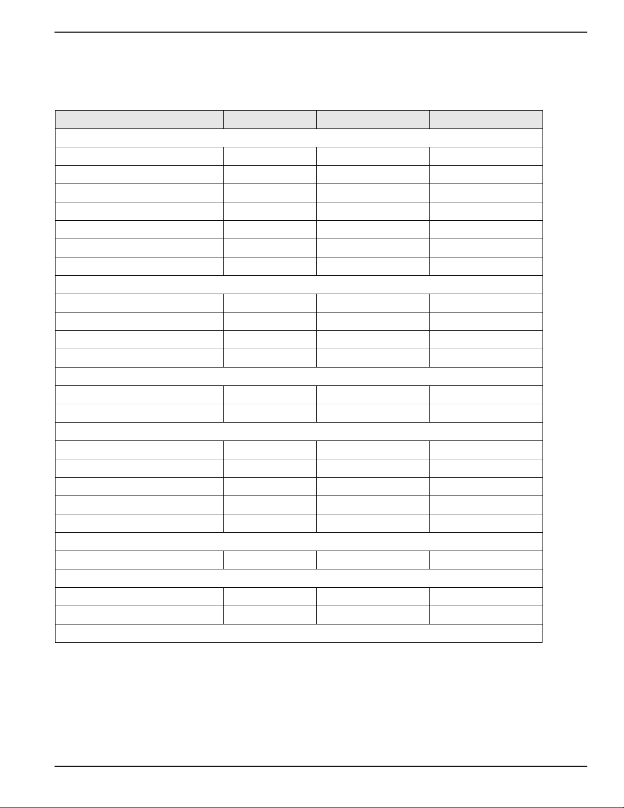
Specifications
DESCRIPTION UNITS MLT3060M MLT3060K
Engine
EPA Tier — 4f 4f
Fuel Consumption—100% Prime gph (Lph) 0.47 (1.78) 0.50 (1.89)
Fuel Consumption—75% Prime gph (Lph) 0.35 (1.32) 0.38 (1.44)
Fuel Consumption—50% Prime gph (Lph) 0.24 (0.91) 0.25 (0.95)
Battery Type—Group Number — 24 24
Battery Voltage quantity per unit 12V (1) 12V (1)
Battery Rating amp-hours 440 CCA 440 CCA
Generator
Output - Standby kW (kVA) 6.0 (6.0) 6.0 (6.0)
General Information
Output Voltage volts 120/240, single phase 120/240, single phase
Output Amperes 120V (240V) amperes 50 (25) 50 (25)
Frequency Hz Hertz 60 60
Weights
Dry Weight lbs (kg) 1640 (744) 1657 (752)
Operating Weight lbs (kg) 1856 (842) 1873 (850)
Capacities
Fuel Tank Volume gal (L) 30 (114) 30 (114)
Usable Fuel Volume gal (L) 30 (114) 30 (114)
Coolant (including engine) qt (L) 4.5 (4.3) 4.8 (4.5)
Oil (including filter) qt (L) 3.8 (3.6) 5.4 (5.1)
Maximum Run Time hours 64 60
AC Distribution
Circuit Breaker Size amperes 30 30
Trailer
Hitch—Standard — 2 in. Ball 2 in. Ball
Maximum Tire Pressure psi (kPA) 50 (345) 50 (345)
Specifications are subject to change without notice.
Owner’s Manual for MLT3060M-K Light Tower 13
Page 18

General Information
D
B
A
E
C
A
B
C
D
E
Unit Dimensions
Figure 2-1. Unit Dimensions
MLT3060M/K 170 in. (4.32 m) 68 in. (1.73 m) 30 ft (9.14 m) 49 in. (1.25 m) 98 in. (2.49 m)
Specifications are subject to change without notice.
14 Owner’s Manual for MLT3060M-K Light Tower
ABCDE
Page 19

General Information
Unit ID Tag
Located on inside
of rear panel
VIN
Tag
TIRE AND LOADING INFORMATION
RENSEIGNEMENTS SUR LES
PNEUS ET LE CHARGEMENT
SEE OWNER’S
MANUAL FOR
ADDITIONAL
INFORMATION
VOIR LE
MANUEL DE
L’USAGER
POUR
PLUS DE
RENSEIGNEMENTS
MANUFACTURED BY/FABRIQUE PAR: Generac Mobile Products LLC DATE: 00/0000
GVWR/PNBV: 000KG (0000LBS) COLD INF. PRESS./
PRESS. DE
V.I.N./N.I.V.:
00000000000000000
TYPE:
TRAILER
MODEL:
XXX000
GAWR / PNBE TIRE / PNEU RIM / JANTE GONF A FROID - KPA(PSI/LPC) SGL / DUAL
EACH
AXLE
THIS VEHICLE CONFORMS TO ALL APPLICABLE STANDARDS PRESCRIBED UNDER THE U.S. FEDERAL MOTOR VEHICLE SAFETY STANDARDS(FMVSS) AND CANADIAN
MOTOR VEHICLE SAFETY REGULATIONS IN EFFECT ON THE DATE OF MANUFACTURE.
CE VEHICULE EST CONFORME A TOUTES LES NORMES QUI LUI SONT APPLICABLES EN VERTU DU REGLEMENT SUR LA SECURITE DES VEHICULES AUTOMOBILES DU CANADA EN VIGUEUR A LA DATE SA
FABRICATION.
The weight of cargo should never exceed 0000KG (0000LBS)
Le poids du chargement ne doit jamais depasser 0000KG (0000LBS)
Serial Number
V
A
Model
KVA
Manufacturing Code
1 ph. 1.0PF
3 ph. .8PF
3 ph. 1.0PF
KW
Country of Origin
Weight (lbs/kg) RPM/Frequency
Rating
Ins. Class
FOR ELECTRICAL EQUIPMENT
ONLY. POUR MATERIAL
ELECTRIQUE SEULEMENT.
209649
Form: SFC626B
Manufactured by Generac Mobile Products LLC
(920) 361-4442 (800) 926-9768
Unit Serial Number Locations
See Figure 2-2 to locate the unit ID tag and Vehicle Identification Number (VIN) tag on the unit. Important information,
such as the unit serial number, model number, VIN and tire loading information are found on these tags. Record the
information from these tags so it is available if the tags are lost or damaged. When ordering parts or requesting
assistance, you may be asked to provide this information.
Figure 2-2. Serial Number Locations
Owner’s Manual for MLT3060M-K Light Tower 15
Page 20

General Information
A
B
C
D
E
F
G
H
I
J
Component Locations
Figure 2-3. Component Locations
A Mast Rotation Knob F Fuel Fill
B Central Lift Point G Outriggers
C Engine Exhaust H Engine Access
D Forklift Pockets I Battery
E Radiator Access J Control Box
16 Owner’s Manual for MLT3060M-K Light Tower
Page 21

Control Panel
A
B
C
D
E
F
G
H
I
J
K
General Information
Figure 2-4. Control Panel
Owner’s Manual for MLT3060M-K Light Tower 17
Page 22

General Information
Control Panel Features and Functions
(A) Main Circuit Breaker
240V/30A breaker which disconnects power from the
lights and control panel.
(B)
Light Switches (4)
One circuit breaker is supplied for each light.
(C) Ballast Indicator Lights
Indicates power from the ballast to each light.
(D) Engine Start Switch
Keyed switch operates glow plugs, starts and stops
engine.
(E) Glow Plug Indicator (If Equipped)
Indicates operation of the engine glow plugs.
(F) Engine Hour Meter
Keeps track of engine hours for service.
(G) DC Breaker
10A circuit breaker for the engine electrical system.
(H) 120V GFCI Outlet
120V/20A GFCI outlet supplies power for accessories
connected to the generator when the engine is running
and the main circuit breaker is ON (I).
(I) 240V Twist-Lock Outlet
240V/30A outlet supplies power for accessories
connected to the generator when the engine is running
and the main circuit breaker is ON (I).
(J) 120V Breaker
120V/20A circuit breaker for the 120V GFCI outlet.
(K) Circuit Breaker Indicator Light
Indicates the main circuit breaker must be opened
(switched OFF) before starting engine.
18 Owner’s Manual for MLT3060M-K Light Tower
Page 23

General Information
Select
A
B
C
D
E
F
G
H
002353
PowerZone–DLA (If Equipped)
The PowerZone–DLA is an AUTO start controller that
monitors the unit and indicates operational status and
fault conditions. The controller can be programmed to
automatically start or stop based on time schedule, fault
condition, or load demand.
The controller constantly monitors vital generator and
engine functions for a number of preprogrammed alarm
and fault conditions. When a fault condition occurs, the
engine will be shut down automatically and the LCD
window will show the fault that caused the shutdown. To
resume operation, the fault condition must be corrected.
This controller also records a history of unit performance,
which may be viewed at any time and will not be lost
when the controller is powered down.
Figure 2-5. PowerZone–DLA Layout
Controller Features and Functions
(A) Display Window
This window displays the various operating screens. By
viewing these screens, the operator can monitor both the
engine and generator status while the unit is running.
(B) Select LED
This LED illuminates when the unit is running in AUTO
mode.
(C) Start LED
This LED illuminates when the unit is running in MANUAL
mode.
(D) Start Button
This button starts the engine if there are no shutdown
errors and the engine is in “ready to start” status.
(E) Stop Button
This button shuts down the unit and puts the controller
into STOP mode, whether in MANUAL mode or AUTO
mode.
NOTE: To prevent damage to the generator and
connected equipment, remove all loads from the
generator by opening all circuit breakers (switch OFF [O])
before pressing the Stop button.
(F) Stop LED
This LED illuminates when the unit is in STOP mode and
flashes when an Electrical Trip and Shutdown Fault has
occurred.
(G) Select Button
This button confirms entries chosen in the various edit
menus and screens.
(H) Menu Navigation
These buttons (↑, ↓) are used to navigate through the
various operator screens.
Owner’s Manual for MLT3060M-K Light Tower 19
Page 24

General Information
002354
002544
002355
002327
Operator Screens
See Figure 2-6. The operator screens display the most
relevant and critical information an operator will need to
properly configure and use the unit. From these six
screens, the operator can access information necessary
to operate the unit under normal conditions.
Figure 2-6. Operator Screens Location
Home Screen
See Figure 2-7. The Home screen is the default screen
of the controller and displays after the controller is
powered up and the unit management software is
loaded. It displays the controller mode, total operating
hours, hours left until the next service interval, engine
operating status, and engine RPM. If the unit is in AUTO
mode, the Home screen may also display whether the
scheduler or “dusk to dawn” are enabled.
Figure 2-8. Engine Screen
• VBAT: Displays the engine battery voltage. A
normal reading is 12-14V on 12 volt systems and
24-26V on 24V systems (with the engine running).
• OIL: Displays engine oil pressure. Normal
operating pressure is between 35-80 psi (241-552
kPa).
• TEMP: Displays engine coolant temperature.
Normal operating temperature of the unit is
between 100-230°F (38-110°C).
• FUEL LEVEL: Displays remaining fuel level as a
percentage of usable fuel tank capacity.
Lights Screen
See Figure 2-9. The Lights screen enables the operator
to turn the lights ON and OFF. See Light Operation or
Light Operation (With PowerZone Controller, If
Equipped) for more information.
Figure 2-7. Home Screen
Engine Screen
• See Figure 2-8. The Engine screen displays
battery voltage, oil pressure, coolant temperature
and fuel level.
Figure 2-9. Lights Screen
20 Owner’s Manual for MLT3060M-K Light Tower
Page 25

General Information
002329
003779
003780
Scheduler Screen
See Figure 2-10. The Scheduler screen enables the
operator to program specific times for the lights to turn
ON and OFF. Once programmed, the Scheduler will start
the engine and illuminate the lights until the designated
shutdown time.
Figure 2-10. Scheduler Screen
NOTE: This feature will only work in AUTO mode.
Maintenance Screens
See Figure 2-11. The information displayed on the
maintenance screens can be used to identify, diagnose
and troubleshoot unit shutdown conditions and poor unit
performance.
2. To select the required icon, press the ↑ button to
cycle right and the ↓ button to cycle left until the
desired operator screen section is reached.
3. Once the desired icon is at the top, press the
Select () button to enter that operator screen
section.
NOTE: Every time the operator screens are entered, the
home icon will be located at the top of the screen.
Alarms Screen
See Figure 2-12. The Alarms ( ) screen displays all the
alarms, warnings, and engine Diagnostic Trouble Code
(DTC) faults. When an alarm occurs, the controller
automatically switches to this screen and remains there
until the alarm is cleared. The Stop LED also flashes.
Figure 2-12. Alarms Screen
Figure 2-11. Maintenance Screens
Icon Description
Home screen
Alarms screen
Maintenance screen
Event log screen
About screen
To enter the navigation menu, use the following
procedure:
• Warnings are non-critical alarm conditions and do
not affect the operation of the unit. They serve to
draw attention to an undesirable condition. By
default, warning alarms are self-resetting when the
fault condition is removed.
• Electrical trips stop the generator in a controlled
manner. On initiation of the electrical trip condition,
the controller de-energizes all the outputs,
including the lights, to remove the load from the
generator. Once this has occurred, the controller
starts the cooling timer and allows the engine to
cool off-load before shutting down the engine.
• Shutdown alarms stop the generator immediately.
On initiation of the shutdown condition, the
controller de-energizes all the outputs, including
the lights, to remove the load from the generator.
Once this has occurred, the controller shuts the
unit down immediately to prevent further damage.
• DTC faults are displayed by the controller.
1. Press both the ↑ and ↓ buttons simultaneously.
Owner’s Manual for MLT3060M-K Light Tower 21
Page 26

General Information
003781
003782
Table 2-1. Possible DTC Faults
Fault DTC Description
Check Engine
Fault
Low Oil Pressure
Maintenance Screen
See Figure 2-13. The Maintenance screen ( ) displays
the maintenance alarms configured into the controller.
The three alarms are for servicing the fuel filter, oil filter,
and air filter.
A fault not recognized by the controller
has been detected. Contact the engine
manufacturer for support.
Engine oil pressure has fallen below
its configured low oil pressure alarm
level.
Underspeed
Overspeed
Low Fuel Level
Battery Under/
Over Voltage
Engine speed has fallen below its
configured underspeed alarm level.
Engine speed has risen above its
configured overspeed alarm level.
Engine’s fuel level has fallen below its
configured low fuel level alarm.
Engine’s DC supply has fallen below
or risen above its configured alarm
level.
To view the active alarms, repeatedly press the ↑ and ↓
buttons until the LCD window displays the alarm.
Continue to press the ↑ and ↓ buttons to cycle through
the alarms.
To exit the alarm screen, press the ↑ and ↓ buttons
simultaneously to enter the navigation menu. Once
entered, cycle to the desired operator screen.
NOTE: The alarm condition must be corrected before a
reset will take place. If the alarm condition remains, it is
not possible to reset the unit. The exception to this is the
Low Oil Pressure alarm and similar ‘active from safety on’
alarms, as the oil pressure is low with the engine at rest.
Figure 2-13. Maintenance Screen
Event Log Screen
See Figure 2-14. The controller’s event log ( ) displays
a list of the last 15 recorded electrical trips or shutdown
events and the engine hours at which they occurred.
Once the log is full, any subsequent electrical trip or
shutdown alarm overwrites the oldest entry in the log.
Therefore, the log always contains the most recent
shutdown alarms.
To clear alarms that stop the generator, see Resetting
the Maintenance Alarms (If Equipped).
NOTE: The LCD backlight is ON if the unit has sufficient
voltage while the unit is turned ON, unless the unit is
Figure 2-14. Event Log Screen
cranking. In this case, the backlight is turned OFF.
If the controller is left in STOP mode for a period of
inactivity, the controller enters POWER SAVE mode. To
‘wake’ the controller, press the Stop (O) button.
To view the event log:
1. Press both ↑ and ↓ buttons simultaneously to
display the navigation menu.
2. Cycle to the event log section and press the Auto
button to enter.
3. Repeatedly press the ↑ or ↓ buttons until the LCD
window displays the desired event.
Continuing to press down the ↑ or ↓ buttons will cycle
through past alarms. Eventually the most recent alarm
will display and the cycle begins again.
To exit the event log, press the ↑ and ↓ buttons
simultaneously to enter the navigation menu. Once
entered, cycle to the desired operator screen.
22 Owner’s Manual for MLT3060M-K Light Tower
Page 27

About Screen
003783
See Figure 2-15. The About ( ) screen contains
information about the controller such as the controller’s
date and time, the product and USB identification
number, and the application and engine version.
Figure 2-15. About Screen
General Information
Owner’s Manual for MLT3060M-K Light Tower 23
Page 28

General Information
This page intentionally left blank.
24 Owner’s Manual for MLT3060M-K Light Tower
Page 29

Section 3: Operation
DETAIL C
DETAIL D
DETAIL G
DETAIL H
H
J
F
H
F
A
G
E
D
C
B
D
E
003789
(000260a)
High Voltage. Verify area above unit is clear
of overhead wires and obstructions. Contact
with high-voltage power lines will result in
death or serious injury.
DANGER
Light Tower Setup
Operation
Figure 3-1. Set Up Outriggers and Jacks
4. A grounding stud (C) is located on the control box.
For grounding requirements, follow the National
Electrical Code (NEC), state, and local regulations.
5. See Detail E. Pull the locking pin (D) on the
outrigger (E) and pull each outrigger out until the
spring loaded locking pin snaps back into place.
Pull the locking pin on the outrigger jack and rotate
each jack 90° so the jack pad is facing down.
1. For maximum light coverage, position the unit at
ground level or in a spot higher than the area being
illuminated by the lamps.
NOTE: The mast extends up to 30 ft (9.14 m).
2. See Figure 3-1. Place the unit on firm ground that
is relatively flat, and then block the wheels (A) to
keep it from moving. This will make it easier to level
the unit.
3. Pull the locking pin (B) on the tongue jack and
rotate the jack 90°. Reinstall the locking pin. Turn
the jack handle clockwise to raise the trailer tongue
off of the towing vehicle.
Owner’s Manual for MLT3060M-K Light Tower 25
Reinstall the locking pin.
6. Pull the locking pin on the rear jack (F) and rotate
the jack 90°. Reinstall the locking pin. Rotate the
jack handle clockwise to start leveling the trailer
(see Detail G). Adjust all four jacks by rotating their
handles (G) clockwise until they are firmly in
contact with the ground and the trailer is as level as
possible.
7. See Detail H. Before raising the mast, it may be
necessary to adjust the lamps. The lamps may be
adjusted up, down, left or right by simply aiming
them in the desired direction.
Page 30

Operation
(000100a)
WARNING
Consult Manual. Read and understand manual
completely before using product. Failure to
completely understand manual and product
could result in death or serious injury.
WARNING
Tipping hazard. Extend the outriggers and level the unit
before raising the mast. Keep the outriggers extended
while the mast is up. Failure to do so could cause the unit
to tip and fall and could result in death or serious injury.
(000266)
DANGER
Electrocution. DO NOT use the unit if
electrical cord is cut or worn through. Doing
so will result in death or serious injury.
(000263a)
DETAIL A DETAIL C
STOP
DETAIL E
DETAIL G
B
G
F
H
A
E
C
B
D
003790
Prestart Checklist
Before starting the unit, all items in the prestart checklist
must be completed. This checklist applies to both manual
and remote starting of the unit.
Verify all maintenance procedures are up to date. For
more information, refer to General Maintenance and
Table 4-1.
The unit must be level.
The unit must be dry. Look for water inside or near
the unit; dry if needed.
For grounding requirements, follow the National
Electrical Code (NEC), state and local regulations.
Verify the main circuit breaker is OFF (O).
Verify all circuit breakers are OFF (O).
Inspect all electrical cords; repair or replace any that
are cut, worn, or bare.
Verify all winch cables are in good condition and
centered on each pulley. Do not use if cables are
kinked or beginning to unravel.
Check oil, coolant, and fuel levels. For more
information, refer to General Maintenance.
Verify battery connections are secure.
Raising the Mast
1. Set up and level the unit. See Light Tower Setup.
Turn the battery disconnect switch ON, if equipped.
Check the engine fan belt tension and condition.
Check the engine fan belt guard.
Check the engine exhaust system for loose or rusted
components.
Verify all covers are in place and secure.
Figure 3-2. Pulley Locations
26 Owner’s Manual for MLT3060M-K Light Tower
Page 31

Operation
WARNING
Tipping hazard. Do not extend the mast beyond the
colored mark on the second mast section. The unit
can become unstable and tip or fall, causing injury.
(000262)
WARNING
Personal Injury. Stop immediately if the mast hangs
up or the winch cable develops slack. Excess slack
could cause the mast to collapse, resulting in personal
injury or equipment damage.
(000265)
I
O
I
O
I
O
I
O
003791
003792
2. See Figure 3-2. Remove mast cradle locking pin
from mast cradle (A).
3. Check the mast cables for excessive wear or
damage. Verify the cables are properly centered in
each pulley (B). Check the electrical cord for
damage.
4. Remove the safety pin from the mast lock bar (C).
Using the handle for the lower mast winch (D),
raise the mast until it is vertical and the tab on the
mast is positioned into the mast lock. The mast
lock bar should snap into place automatically.
Secure the lock with the safety pin (E).
5. Rotate the mast by loosening the mast rotation
knob (H) at the bottom of the mast. Turn the mast
until the lights face in the desired direction, and
then tighten the mast rotation knob to secure the
mast in position.
6.
Use the winch (F) to slowly extend the mast, making
sure that the coiled electrical cord is extending at
the top sections of the mast. STOP extending the
mast when the colored mark (G) on the second
mast section is visible as seen in Detail G.
1. See Figure 3-3. Verify the main circuit breaker and
individual circuit breakers for each of the lights are
OFF (O).
Figure 3-3. Circuit Breakers in OFF (O) Position
NOTE: When the red “turn main breaker OFF” light is
illuminated, the main circuit breaker must be turned OFF
(O).
2. See Figure 3-4. Turn the key on the Engine Start
switch to the left GLOW PLUG position and hold
the key in place for five seconds, or until the glow
plug indicator turns red.
IMPORTANT NOTE: Contact a Generac Mobile
Products Authorized Dealer immediately if the mast
hangs up or the winch cable develops slack.
Starting the Unit
NOTE:
drained, it may be necessary to bleed the fuel lines before
starting. Refer to the engine manual supplied with the unit.
If the engine was run out of fuel or the fuel tank was
OFF
GLOW
RUN
PLUG
START
Figure 3-4. Activate Glow Plug
NOTE: The MLT3060K is not equipped with a glow plug
indicator.
Owner’s Manual for MLT3060M-K Light Tower 27
Page 32

Operation
GLOW
PLUG
OFF
RUN
START
003793
GLOW
PLUG
OFF
RUN
START
003794
002354
3. See Figure 3-5. As soon as it is glowing, turn the
key to the right START position and hold it until the
engine cranks and starts running.
Figure 3-7. Select AUTO or MANUAL Mode
Figure 3-5. Crank Engine
4. See Figure 3-6. Release the key, it will move to
RUN.
Figure 3-6. Release Key
Preparing for Start-Up (with PowerZone Controller, If Equipped)
NOTE:
drained, it may be necessary to bleed the fuel lines before
starting. Refer to the engine manual supplied with the unit.
Select AUTO or MANUAL Mode
See Figure 3-7. Using the arrows on the PowerZone–
DLA, select either AUTO or MANUAL on the Home
screen.
If the engine was run out of fuel or the fuel tank was
• AUTO mode is required for programming
automatic start and stop times (see Scheduler
Screen).
• MANUAL mode is used for on-demand control of
the lights and convenience outlets.
Manually Starting the Unit
STOP mode is the default start-up setting for all units
equipped with the PowerZone–DLA. Use the following
procedure to start the generator in MANUAL mode.
1. Verify the 240VAC outlet breaker is switched OFF
(O).
2. Switch the main circuit breaker ON (I).
3. Verify that the Load Sense switch is OFF.
4. When the controller powers up, the Home screen
displays on the LCD screen and the Stop LED
illuminates to indicate that the controller is in STOP
mode. Press the Start button to initiate the startup
procedure. Assuming there are no existing engine
faults, the engine will start and the Start LED will
illuminate.
NOTE: The engine can be started from any screen. It
may take a few seconds for the engine to run smoothly
and reach its governed operating speed.
5. If the engine does not start after the first cranking
attempt, the engine will pause for 15 seconds to
allow the starter to cool. The controller backlight
will go out. The engine will make two more
attempts to start for a total of three crank cycles.
6. If the engine does not start and run within three
starting cycles, the LCD screen will display the
“Fail to Start” alarm. The starting sequence can be
repeated after the starter cools for at least two
minutes. Pressing the Stop (O) button will clear the
alarm and reset the controller.
7. Once the engine starts, engine speed will increase
to 1800 rpm. The engine may hunt or change
speeds until operating speed is reached. After a
few minutes at operating speed, the Home screen
will display the mode of the unit, the engine status,
the engine RPM, and any active program
(Scheduler or Dawn to Dusk) in AUTO mode.
28 Owner’s Manual for MLT3060M-K Light Tower
Page 33

Operation
(000277)
WARNING
Burn hazard. Never operate lights with a
damaged or missing lens cover. Lamps are
hot and pressurized while in use. Unprotected
lamps can shatter, causing severe injury.
WARNING
Burn Hazard. Allow bulb fixture to cool 10-15
minutes before handling or lowering mast.
Failure to do so could result in serious injury.
(000358)
002383
(000278)
WARNING
Burn hazard. Lamps become extremely hot
while in use. Allow 10–15 minutes for cooling
before handling or lowering mast. Touching a
hot lens or fixture can cause severe burns.
8. Check the generator for excessive noise or
vibration and any leaking coolant, oil, or fuel before
applying loads.
9. Once the engine is running, allow it to reach
normal operating temperature turning on the outlet
breaker.
10. Switch the export outlet breaker ON (I). Then add
any loads attached to the outlets. You will notice a
change in engine sound when a load is applied to
the unit.
Light Operation
Light Operation (With PowerZone Controller, If Equipped)
See Figure 3-8. The lights are turned ON and OFF using
the PowerZone–DLA. To view the light screen, press the
↑ button three times from the Home screen.
NOTE: The lights can only be turned ON and OFF while
the unit is running in MANUAL mode. They operate
automatically in AUTO mode.
1. Once the engine is up to temperature and running
smoothly, switch the main circuit breaker ON (I).
To turn the light(s) ON, press the Select () button. To
turn the light(s) OFF, press the Select () button.
1. See Control Panel for the following steps. Switch
the main circuit breaker ON (I).
2. Turn each individual light switch ON (I), one at a
time.
NOTE: The ballast indicator lights will turn ON and
continue to get brighter as the lights warm up, and then
remain ON. This confirms power is coming from the
ballasts to the lights.
If an indicator light does not turn ON, the ballast may
need to be serviced. If the indicator light turns ON and
stays lit but the related light is not illuminated, check the
bulb or the mast wiring. See Troubleshooting the
Lights.
The lights require a warm up period of 5-15 minutes
before they reach full output. If the lights are shut down,
they require a cool down period of approximately ten
minutes before they can be switched ON again.
The light tower uses four 1000W or 1050W bulbs. When
checking or replacing the bulbs, wipe them with a clean
cloth to avoid leaving any grease, oil residue or
fingerprints on the glass. Any residue can create a hot
spot on the bulb, causing premature bulb failure.
Owner’s Manual for MLT3060M-K Light Tower 29
Engine Derating
All units are subject to derating for altitude and
temperature. Derating reduces the available power for
operating tools and accessories connected to the
receptacles. Typical reductions in performance are 2-4%
for every 1000 ft (305 m) of elevation and 1% per 10ºF
(5.6ºC) increase in ambient air temperature over 72ºF
(22ºC).
Figure 3-8. Lights Screen
Page 34

Operation
120V
240V
BREAKER BREAKER
240V
BREAKER
NEUTRAL BONDED TO FRAME
I
O
003796
A
B
Wet Stacking
The unit is powered by a diesel engine. Diesel engines
are subject to “wet stacking” if lightly loaded. Wet
stacking occurs when an engine is run at less than 30%
of its full load capacity, causing unburned fuel to
accumulate in the exhaust system. Wet stacking can be
detected by continuous black exhaust when the unit is
under a constant load. It can also cause fouling of
injectors and buildup on engine valves. Diesel engines
operate properly when applied loads are between 30%
and 100% capacity. Appropriate generator sizing is
determined by the anticipated load.
If the unit is in a wet stack condition, load the unit heavily
for five hours or until the exhaust is clear.
Customer Convenience Outlets
See Figure 3-9. The unit is equipped with two
convenience outlets for powering accessories or tools
from the generator. Power is supplied to the outlets any
time the engine is running and the 240VAC outlet breaker
is switched ON (I). Each outlet has an individual circuit
breaker, located on the control box. See Control Panel.
Shutting Down the Unit
Check with personnel using power supplied by the unit
and let them know the power is going to be turned off.
Verify the power shutdown will not create any hazards by
accidentally turning off equipment that needs to remain
running (pumps, compressors, lights, etc.).
1. Remove all loads from the outlets.
2. Switch the individual circuit breakers for each light
OFF (O).
3. Switch the main circuit breaker OFF (O).
4. Turn the Engine Start switch OFF (O).
NOTE: Disconnect the battery if the unit is to be stored
for an extended period. Refer to the engine operator’s
manual for additional extended storage procedures.
Shutting Down the Unit (with PowerZone Controller, If Equipped)
Check with personnel using power supplied by the unit
and let them know the power is going to be turned off.
Verify the power shutdown will not create any hazards by
accidentally turning off equipment that needs to remain
running (pumps, compressors, lights, etc.).
1. Remove all loads from the outlets.
2. Turn the lights OFF using the controller.
3. Switch the outlet breaker OFF (O).
4. Press the Stop (O) button.
5. After the unit shuts down, switch the main circuit
breaker OFF (O).
Figure 3-9. Location of Outlets
A 120V GFCI Outlets
B 240V Twist-lock Outlet
See Figure 3-9. The circuit breakers are labeled with the
corresponding voltage for the receptacle they protect.
With all of the lights OFF, full generator power output is
available to the receptacles.
NOTE: All equipment or load panels connected to the
generator MUST be properly grounded. If these
appliances do not have grounded plugs, a ground wire
MUST be added between the equipment and the
grounding stud on the receptacle panel per the National
Electrical Code (NEC), state, and local regulations.
NOTE: Disconnect the battery if the unit is to be stored
for an extended period. Refer to the engine operator’s
manual for additional extended storage procedures.
Automatic Shutdown
This unit is equipped with a low oil pressure and high
coolant temperature automatic shutdown system. This
system will automatically shut off the fuel supply to stop
the engine if oil pressure drops too low or the engine
exceeds normal operating temperature. Return the main
circuit breaker to the STOP position to reset the unit after
the cause of shutdown has been determined.
Lower Radiator Hose Heater (If Equipped)
The lower radiator hose heater is designed to prevent
engine coolant from freezing in extreme cold weather
conditions. While the heater is designed to be operated
overnight if necessary, two to five hours of heating just
prior to starting is usually sufficient for proper engine
starting.
30 Owner’s Manual for MLT3060M-K Light Tower
Page 35

Operation
WARNING
Personal Injury. Stop immediately if the mast hangs
up or the winch cable develops slack. Excess slack
could cause the mast to collapse, resulting in personal
injury or equipment damage.
(000265)
NOTE: Use the lower radiator hose heater only in its
designated location. Improper use can damage the
engine.
Perform the following steps when operating a unit
equipped with a lower radiator hose heater.
1. Verify the unit is level so as to maintain proper
orientation of the heater while it is in operation.
2. Verify the cooling system is full of the proper
mixture of water and engine coolant before each
heater use.
3. Use only an undamaged, outdoor rated, threeprong grounded 120VAC extension cord with a
minimum amperage rating of 10A. Connect the
cord to a properly grounded 120VAC, GFCI outlet.
4. Before starting the engine, unplug the extension
cord from the power first, then unplug the heater
cord set from the extension cord.
Spark Arrester (If Equipped)
A spark arrester, installed on the MLT exhaust, may be
required by code in certain municipalities. Check with the
local authority having jurisdiction to determine whether or
not a spark arrester must be installed on the unit before
operation.
Lowering the Mast
1. Shut down the lights and engine. See Shutting
Down the Unit (with PowerZone Controller, If
Equipped). Allow the lights to cool 10-15 minutes
before lowering the mast.
2. Loosen the mast rotation knob. Rotate the mast
until the white arrows are aligned and the metal
stop tabs are touching. Tighten the mast rotation
knob.
3. Turn the upper mast winch handle
counterclockwise to collapse the mast to its lowest
position. Ensure the coiled electrical cord does not
get caught in, or pinched by, the mast while it is
being lowered.
IMPORTANT NOTE: Contact an Generac Mobile
Products Authorized Dealer immediately if the mast
hangs up or the winch cable develops slack.
4. Release the mast lock by pulling the safety pin on
the mast lock and pulling the lock bar free. Turn the
handle of the lower mast winch counterclockwise
until the mast rests in the transport cradle.
Owner’s Manual for MLT3060M-K Light Tower 31
NOTE: If the mast lock bar does not pull free, activate
the lower winch slightly to relieve pressure on the mast
bar.
5. After the mast is completely down, insert the mast
cradle locking pin and secure it with the safety pin.
6. I
f the unit is going to be moved, remove the lights
from the mast and stow for transportation
Removing the Lights for Transportation.
. See
Removing the Lights for Transportation
On units equipped with quick disconnect fittings for the
lights, disconnect the power cords from the junction box
at the top of the mast. Replace the dust caps on the
junction box. On hard wired units, remove the junction
box cover, located on the top of the mast, and disconnect
ONLY the mast light wires from the connectors. To
release the mast light wires from the connectors, flip the
locking levers down and pull out the appropriate wires.
Remove the lights by removing the wing nut that holds
the light fixture bracket to the cross tube. Attach the lights
to the storage brackets (if equipped) located on the mast
tube on either side of the central lift point.
NOTE: When installing the lights for use, verify the star
washer is in place between the trunnion and T-handle.
Towing the Unit
Once the engine is shut down and the mast and lights are
properly stowed, follow these steps to prepare the unit for
towing.
1. Raise the outrigger jacks completely and release
the locking pins to rotate them up into the travel
position. Verify the locking pins snap into place.
Release the outrigger locking pins and slide the
outriggers into the trailer frame until the locking
pins snap into place.
2. Use the tongue jack to raise or lower the trailer
onto the hitch of the towing vehicle. Lock the hitch
coupling and attach the safety chains or cables to
the vehicle. Remove the tongue jack locking pin
and rotate the jack into the travel position. Replace
the locking pin.
3. To ensure proper operation of the jacks, lubricate
the grease fittings located on the leveling jacks.
See Jack Maintenance. For maintenance interval
information, see to Table 4-1.
4. Connect any trailer wiring to the tow vehicle. Check
for proper operation of the directional and brake
lights.
5. Verify the enclosure is properly latched.
6. Check for proper inflation of the trailer tires. For
maximum tire pressures, see Specifications.
Page 36

Operation
5
2
3
4
1
003754
A
003797
A
B
B
7. See Figure 3-10. Check the wheel lugs. Tighten or
replace any lugs that are loose or missing. If a tire
has been removed for axle service or replaced,
tighten the lugs, in the order shown, to the
following specifications:
Figure 3-10. Tightening Wheel Lugs
a. Start all lug nuts by hand.
b. First pass: tighten to 20-25 ft-lbs (27-33 Nm).
c. Second pass: tighten to 50-60 ft-lbs (67-81 Nm).
d. Third pass: tighten to 90-120 ft-lbs (122-162 Nm).
Lifting the Unit
Follow these steps to prepare the unit for lifting:
1. Verify the equipment being used to lift the unit is in
good condition and has sufficient capacity. For
approximate weights, see Specifications.
2. Close and lock all hoods and doors.
3. See Figure 3-12. Stow the mast and lights in the
travel position as shown.
4. Always remain aware of people and objects around
the unit while preparing, maneuvering, and lifting
the unit.
• When lifting the unit, attach any slings, chains or
hooks directly to the central lift point (A).
• Use the forklift pockets (B) with care. Lift only from
the side. Avoid approaching the unit at an angle,
as this can permanently damage the forklift
pockets, tires, or cabinet. Verify the forklift tines
are clear of any obstructions before lifting.
NOTE: After the first road use, re-torque the lug nuts in
sequence.
8. Maximum recommended speed for highway towing
is 45 mph (72 km/h). Recommended off-road
towing speed is not to exceed 10 mph (16 km/h) or
less, depending on the terrain.
Tying the Unit Down
When securing the unit for transportation, verify the
equipment being used to fasten the unit is in good
condition and has sufficient strength to hold the unit in
place during transport.
See Figure 3-11. Use the tie-down points (A) as shown.
Figure 3-12. Lift Points
Figure 3-11. Tie-Down Points
32 Owner’s Manual for MLT3060M-K Light Tower
Page 37

Section 4: Maintenance
CAUTION
(000306)
Equipment Damage. Failure to perform a daily
inspection could result in damage to the unit.
Maintenance
Emissions Information
For warranty information, please refer to the diesel
engine manual supplied with this unit.
Daily Walk-Around Inspection
Perform a walk-around inspection of the unit every day
before starting the unit. Look for conditions that could
hinder performance or safety, such as (but not limited to):
• Oil, coolant and fuel leakage
• Blocked vents
• Loose or missing hardware
• Loose or broken electrical connections.
Inspect the fan belt for cracks, fraying, or stretching.
Verify the belt is properly seated in the pulley grooves.
Replace the belt according to the manufacturer’s
recommendations.
2. Verify the circuit breakers are switched OFF (O).
3. Disconnect the negative (–) terminal on the battery.
4. Attach a “Do Not Start” sign to the control panel.
This will notify everyone that the unit is being
serviced and will reduce the chance of someone
inadvertently trying to start the unit.
Cleaning the Unit
Always clean the Light Tower after each use to remove
dust, grease, mud, or spilled fuel or oil. Use soft, clean
rags to wipe the cabinet exterior and control panel. Lowpressure compressed air (less than 40 PSI [276 kPa])
can also be used to remove dust and debris from the
cabinet interior.
This unit contains sensitive electronic components that
can be damaged by high pressure and heat. Therefore:
• Do not wash the unit with a high pressure hose or
power washer.
• Do not wash the engine block or fuel tank with a
power washer or steam cleaner. Water may enter
the cabinet and collect in the generator windings or
other electrical parts, causing damage.
General Maintenance
Poorly maintained equipment can become a safety
hazard. In order for the equipment to operate safely and
properly over a long period of time, periodic maintenance
and occasional repairs are necessary. DO NOT perform
routine service (oil and filter changes, cleaning, etc.)
unless all electrical components are shut off.
Regular maintenance will improve performance and
extend engine/equipment life. Generac Mobile Products
LLC recommends that all maintenance work be
performed by a Generac Mobile Products Authorized
Dealer. Regular maintenance, replacement or repair of
the emissions control devices and systems may be
performed by any repair shop or person of the owner’s
choosing. However, to obtain emissions control warranty
service free of charge, the work must be performed by a
Generac Mobile Products Authorized Dealer or
authorized Mitsubishi engine dealer depending on the
repair. See the emissions warranty.
Preparing for Service
Before servicing the unit, always follow the instructions
listed below.
1. If unit is equipped with the PowerZone controller,
verify the main circuit breaker is OFF. Otherwise,
verify the key switch is in the OFF position.
Inspecting the Unit
•
If the unit is stored outside, check for water inside
the cabinet and generator before each use. If wet,
dry the unit thoroughly before starting.
• Inspect condition of electrical cords. DO NOT use
the unit if insulation is cut or worn through.
• Verify winch cables are in good condition and
centered on each pulley. DO NOT use a cable that
is kinked or starting to unravel.
• Verify the safety pins for the mast lock rod and
mast lock bar are present and secured with a
chain. Check that the spring located in the mast
lock bar is not broken or missing. Check the
operation of the mast lock bar.
• Verify the wheel lugs are present and properly
tightened. Refer to Towing Safety.
• Check the coolant level daily by inspecting the
level in coolant overflow jug located near the
radiator. Refer to the engine operator’s manual for
coolant recommendations and proper mixture.
Normal operating level is between the ‘full’ and
‘add’ markings on the overflow jug.
•
AFTER ENGINE IS STOPPED AND COMPLETELY
, coolant may be added directly to the coolant
COOL
overflow jug.
•
Check the oil level daily. Refer to the engine
operator’s manual for the appropriate oil specification.
Owner’s Manual for MLT3060M-K Light Tower 33
Page 38

Maintenance
Verify the oil is correct for special operating conditions
such as a change in season or climate.
• DO NOT start the unit if the engine oil level is
below the ADD mark on the dipstick.
• Normal operating level is in the cross-hatch
pattern between the full and add markings on
the dipstick.
•A
dd oil only if the oil level is below the add mark
on the bottom of the cross-hatch pattern on the
dipstick.
DO NOT OVERFILL
the crankcase.
• Check the fuel level.
• If the unit is connected to a remote start or transfer
switch, make sure the remote switch is also off and
tagged.
NOTE: If the engine was run out of fuel or the fuel tank
was drained, it may be necessary to bleed the fuel lines.
Refer to the engine operator’s manual supplied with the
unit.
Basic Maintenance Schedule
Refer to the original equipment manufacturer’s operating
manual for a complete list of maintenance requirements.
Failure to comply with the procedures as described in the
engine operator’s manual will nullify the warranty,
decrease performance and cause equipment damage or
premature equipment failure. Maintenance records may
be required to complete a warranty request.
Use the schedule in the following tables as a guide for
regular maintenance intervals. For additional or
replacement copies of the engine operator’s manual,
contact a Generac Mobile Products Authorized Dealer.
34 Owner’s Manual for MLT3060M-K Light Tower
Page 39

Table 4-1. Basic Maintenance Guide - MLT3060M
Maintenance
Item Daily
Check Oil Level
Check Coolant Level
Check Fuel Level
Check Tire Pressure
Inspect Wheel Bearings
Check All Electrical Connections
Inspect Radiator Fins For Debris;
Clean As Required
Inspect Light Tower Winch For Proper Operation
Fuel Tank—Drain Water
Check Air Cleaner
Replace Engine Oil And Oil Filter
Belt And Belt Tension—Inspect And Adjust
Replace Fuel Filter
50
Hours
250
Hours
400
Hours
500
Hours
1000
Hours
As
Required
*
Drain And Clean Fuel Tank
Check Glow Plugs
Lubricate Leveling Jacks
Tighten Bolts And Nuts On The Engine
Replace Heated Fuel Filter (If Equipped)
Inspect Engine Starting Battery
Clean, Check And Replace Air Cleaner Element
Fuel System—Bleed Air
Fuel/Water Separator—Drain Water
**
*
.* Perform after the initial 50 hours of operation, then on the regularly scheduled interval indicated in the schedule above.
** Certain conditions may require the fuel tank to be drained and cleaned more often. When operating in extremely
dusty conditions, clean the fuel tank as often as necessary.
Owner’s Manual for MLT3060M-K Light Tower 35
Page 40

Maintenance
Table 4-2. Basic Maintenance Guide - MLT3060K
Item Daily
Check Oil Level
Check Coolant Level
Check Fuel Level
Check Tire Pressure
Inspect Wheel Bearings
Check All Electrical Connections
Inspect Radiator Fins For Debris; Clean As Required
Inspect Light Tower Winch For Proper Operation
Check Fuel Pipes and Clamp Bands
Clean Air Filter Element
Clean Fuel Filter
Check Fan Belt Tightness
Fuel/Water Separator—Drain Water
50
Hours
100
Hours
200
Hours
400
Hours
500
Hours
Yearly
Check Radiator Hoses and Clamp Bands
Change Engine Oil
Check Intake Air Line
Replace Oil Filter Cartridge
Replace Fuel Filter Cartridge
Clean Fuel/Water Separator
Lubricate Leveling Jacks
Remove Sediment in Fuel Tank
Replace Fan Belt
Replace Air Filter Element
*
*
**
.* Change the engine oil and oil filter after the initial 50 hours of operation, then at the appropriate interval thereafter.
** Replace the air cleaner element yearly, or after six cleanings, whichever occurs first.
36 Owner’s Manual for MLT3060M-K Light Tower
Page 41

Maintenance
003784
Resetting the Maintenance Alarms (If Equipped)
The PowerZone–DLA will display a warning message
when the unit is due for maintenance or service. The
maintenance or service interval is set at 750 hours of
engine running time. Once the unit has been serviced,
the appropriate maintenance alarm reminder needs to be
reset. The following procedure demonstrates how to
reset the maintenance alarms:
1. With the unit shut down, switch the main circuit
breaker ON (I). After initialization, the controller will
toggle automatically to the Home screen.
2. Press ↑ and ↓ simultaneously to enter the
navigation menu.
3. See Press ↑ or ↓ to move to the top of the
screen. Press to enter the Maintenance screen.
4. Press ↑ or ↓ to highlight the desired alarm that
needs to be reset. Press to start reset.
5. Enter the pin 4444. To do this, press and then ↑
or ↓ to adjust the first number of the maintenance
pin. Press to continue to the next number.
Winch Use, Operation and Maintenance
Prior to Use
•
Inspect rope or cable and replace if damaged.
• Check mounting hardware for proper torque and
tighten if necessary.
• Gears, ratchet pivot point and shaft bushings must
be kept lubricated with a thin film of oil or grease.
Operation
Raising the Lights:
1. The cable must be securely fastened to the object
being lifted and to the winch drum.
2. Verify the cable and cable attachments are not
damaged. Contact Generac Mobile Products to
order a replacement cable if necessary.
3. Referring to the “Lift / Let Down” decal on the
winch, turn handle according to the specified
direction to lift. The ratchet MUST make a loud
clicking sound while winding the cable.
Figure 4-1. Entering Maintenance Pin
Lowering the Lights:
Referring to the “Lift / Let Down” decal on the winch, turn
handle according to the specified direction to lower. No
clicking will be heard because the brake system is
activated.
Maintenance
The following procedures should be performed at least
annually:
1. The gears and bushings of the winch must be kept
lubricated. Apply a thin film of grease to the gear
teeth, and oil the bushings as needed.
2. The ratchet pawl pivot point must be kept
lubricated with a thin oil.
NOTE: Do not get oil or grease on the brake mechanism.
Owner’s Manual for MLT3060M-K Light Tower 37
Page 42

Maintenance
002540
A
C
B
Jack Maintenance
Before each use, check each jack foot for damage and
remove any mud or debris. The jacks must be clean and
in good operating condition to properly support the unit.
Trailer Wheel Bearings
The trailer axles are equipped with a Zerk grease fitting
to allow lubrication of the wheel bearings without the
need to disassemble the axle hub. Use only a high
quality grease made specifically for lubrication of wheel
bearings, such as Valvoline W615 or equivalent.
See Figure 4-2. To lubricate the wheel bearings:
Figure 4-2. Wheel Bearing Cross Section
1. Remove the small rubber plug (A) from the metal
end cap (B).
2. Attach a standard grease gun fitting to the Zerk
grease fitting (C).
3. Pump grease into the Zerk fitting until fresh grease
is visible around the nozzle of the grease gun.
4. Wipe any excess grease from the axle hub with a
clean cloth and replace the rubber plug.
The minimum recommended lubrication is every 12
months or 12,000 miles (19,312 km). More frequent
lubrication may be required under extremely dusty or
damp operating conditions.
Every six months, or depending on usage, check for play
in each bearing by jacking up the trailer, then trying to
rock the wheel. If further assistance is required, contact
Generac Mobile Products Technical Service at
1-800-926-9768.
38 Owner’s Manual for MLT3060M-K Light Tower
Page 43

Section 5: Troubleshooting
(000139)
WARNING
Risk of burns. Allow engine to cool before
draining oil or coolant. Failure to do so could
result in death or serious injury.
General Troubleshooting
Some of the more common problems are listed in the
table below. This information is intended to be a check or
verification that simple causes can be located and fixed.
It does not cover all types of problems. Refer to the OEM
engine operator’s manual for additional troubleshooting
information. Procedures that require in-depth knowledge
or skills should be referred to a Generac Mobile Products
Authorized Dealer.
Problem Possible Cause Solution
Troubleshooting
Unit cranks, but will not start Fuel level low.
Fuel flow obstructed.
Fuel solenoid inoperable.
Air in fuel system.
Restricted air filter.
Glow plug(s) inoperable.
Unit starts, but stumbles and
dies
High coolant temperature
shutdown
Low oil pressure shutdown Oil level low.
Ambient temperature too
low.
Intake heater inoperable.
Low coolant level.
Blockage in radiator.
Debris on radiator face.
broken coolant pump belt.
cooling fan inoperable.
Oil pump inoperable.
Check fuel level in tank.
Verify fuel pump operation.
Verify fuel solenoid operation.
Inspect air filter for blockage.
Bleed air from fuel system.
Inspect fuel supply hose from tank to fuel filter for cracks and
abrasion.
Check for gelled fuel in fuel system in cold weather, especially at
fuel filter.
Refer to OEM engine operator’s manual for additional
information.
Check if ambient temperature is within unit limits.
Check engine air inlet heater functionality.
Allow engine to cool, then check coolant level in radiator. Add
coolant if needed.
Inspect radiator surroundings for blockage and remove any
foreign matter.
Inspect for visible leaks. Verify tension of water pump drive belt.
Remove load on generator and restart engine. Verify coolant
temperature and shut engine down immediately if it starts to
overheat.
Check oil level. Add oil if necessary.
Unit stalls when export power
is used
The lights are flashing Dusk-to-dawn sensor
Load exceeds unit rating.
adjustment needed.
Generator frequency too
low.
Turn outlet breaker ON and load sense switch OFF, confirm
generator output is 60hz + or - 2hz. Reapply load.
Adjust the dusk-to-dawn sensor to increase or decrease light
received.
Turn off main breaker.
Check if AC frequency is >40hz.
If problems persist, contact Generac Mobile Products at 1-800-926-9768 for assistance.
Owner’s Manual for MLT3060M-K Light Tower 39
Page 44

Troubleshooting
(000278)
WARNING
Burn hazard. Lamps become extremely hot
while in use. Allow 10–15 minutes for cooling
before handling or lowering mast. Touching a
hot lens or fixture can cause severe burns.
(000187)
WARNING
Electrocution. Potentially lethal voltages are generated
by this equipment. Render the equipment safe before
attempting repairs or maintenance. Failure to do so
could result in death or serious injury.
Troubleshooting the Lights
Problem Possible Cause Solution
Mast Lights Off,
Checking Outside the
Control Box
Light fixture is too hot.
Faulty lamp connection.
Lamp broken.
IMPORTANT NOTE: Only a qualified electrician
should troubleshoot or repair electrical problems
occurring in this equipment. Contact Generac Mobile
Products Technical Service at 1-800-926-9768 for
assistance if you have any questions, or if problems
persist.
Allow light to cool 10-15 minutes before restarting.
Check that the lamp is tight in the socket.
Check for broken arc tube or outer lamp jacket, broken or loose components in
lamp envelope, or blackening/deposits inside tube.
Mast Lights Off and
Ballast Indicators on
Control Panel Are Off
Mast Lights On But the
Light Output is Low
Loose lighting connections.
Damaged or loose
electrical cord.
Loose lighting connections.
Generator output incorrect.
Low transformer output.
Fixture and/or lens is dirty.
Lamp worn due to normal
use.
Damaged or loose
electrical connections.
Generator output incorrect.
Low transformer output.
Check the connections inside the mast junction box and each mast light
housing/socket.
Check the mast electrical cord for damage and check the cord connections
inside the control box.
Check the connections inside the control box and inside each ballast box.
Check the incoming voltage to the ballast by checking the available voltage on
the GFCI receptacle. Incoming voltage should be 120V +/- 5V. If voltage is
incorrect, the engine speed may need to be adjusted or generator may require
service.
The voltage from the transformer should read approximately 400VAC as the
light “strikes” (induces an arc), then drop and slowly rise back up to stabilize at
240-260VAC. On hard wired models,
remove the mast junction box cover and insert the wire probes into the
connector blocks for the light and ground. If proper voltage is not achieved,
perform capacitor check to determine if the capacitor or coil needs
to be replaced.
Clean reflective surface inside fixture and both inside and outside surface of
glass lens. Use mild soap and water to clean lens. Other chemicals may have
an adverse effect on the glass.
Replace lamp.
Check the mast coil cord, mast junction box and mast light connections.
Check the incoming voltage to the ballast. Incoming voltage should be 120V +/5V. If the voltage is incorrect, the engine speed may need to be adjusted or the
generator may require service.
The voltage from the transformer should read approximately 400VAC as the light
“strikes” (induces an arc), then drop and slowly rise back up to stabilize at 240260VAC. On hard wired models, remove the mast junction box cover and insert the
wire probes into the connector blocks for the light and ground. If proper voltage is
not achieved, perform capacitor check to determine if the capacitor or coil needs to
be replaced.
One or more lights do not
turn on
40 Owner’s Manual for MLT3060M-K Light Tower
Light breaker tripped.
Lights not turned on.
Check light breakers.
Check electronic control to see if lights are on.
Turn lights on.
Page 45

Section 6: Wiring Diagrams
1
3
2
4
21
43
00175
Mast Junction Box Wiring and Light Connections
Wiring Diagrams
Owner’s Manual for MLT3060M-K Light Tower 41
Page 46

Wiring Diagrams
GEN
N
G
Y
XZ
30 AMP
TWIST
1
2
34567
8
9
10
11
12
LED BOARD
1
2
3 1
2
3 1
2
3 1
2
3
23
14
23
14
MAST CABLE
TO
GND
BAR
TO
GND
BAR
TO
GND
BAR
1
2
34567
8
9
10
TO
GND
BAR
TO
GND
BAR
BK
BL
RD
YL
WT/BK OR BN
WT
GN
8KW UNITS ONLY
8KW UNITS
ONLY
1
GN
WT
3
GN
WT
BK
2
GN
WT
BK
4
GN
WT
BK
BK
20A
30A
RD
RD
BK
BK
BK
BK
WT
GN
RD
YL
RD
BK
BL
WT
YL
RD
BK
BL
BK
RD
GY
RD
RD
RD
RD
RD
RD
GY
GY
BK
BK
BL
BL
BK
RD
YL
RD
BK
BK
RD
RD
BK
RD
BK
CAP 2 CAP 1
CAP 3
CAP 4
..
TRANSFORMER 1
..
TRANSFORMER 2
..
TRANSFORMER 3
..
TRANSFORMER 4
GN
GN
WT
WT
20A
RD RD
BK
BK
BK
BK
BL
BK
RD
YL
BK
RD
YL
BK
RD
YL
WT
WT
WT
WT
WT
WT
15 A
15 A
15 A
15 A
BK BK
RD
RD
GY
BL
BK
RD
MAIN
CB6
CB7
GFCI
CB5
GFCI
CB1
CB1
CB1
CB1
90347_E_06.21.14
AC Wiring
42 Owner’s Manual for MLT3060M-K Light Tower
Page 47

DC Wiring—MLT3060M
RED (PULL)
WHT (HOLD)
BLU (COM)
SOLENOID
RED/YEL
VIO/YEL
BLK/YEL
BLK/YEL
RED/WHT
STARTER SWITCH
HOUR
VIO/YEL
VIO/YEL
BLK/WHT
BLK/WHT
RED
BLK
FUEL
PUMP
10 AMP
CIRCUIT
BREAKER
OIL
PRESSURE
WARNING
SWITCH (N.C.)
SWITCH (N.O.)
WARNING
OVERHEAT
12V BATTERY
STARTER
RELAY
TIME DELAY
GRY/BLU
GRY/VIO
VI/YL
RED
BLK
CONTROL
RESISTANCE
BLK/YEL
GLOW PLUGS
AUX SWITCH
MAIN BREAKER
RD/VI
ALTERNATOR
WARNING LIGHT
"TURN MAIN
BREAKER OFF"
BLK/WHT
BLK
RED/YEL
ORG/YEL
RD/VI
RED/VIO
N/C
N/O
-
+
COM
90340_C_04.23.13
Wiring Diagrams
Owner’s Manual for MLT3060M-K Light Tower 43
Page 48

Wiring Diagrams
(HOLD)
(PULL)
SOLENOID
RD/YL
VI/YL
BK/YL
RD/WT
STARTER SWITCH
HOUR
VI/YL
VI/YL
BK/WT
BK/WT
RD
BK
FUEL
PUMP
10 AMP
CIRCUIT
BREAKER
OIL
PRESSURE
WARNING
SWITCH (N.C.)
SWITCH (N.O.)
WARNING
OVERHEAT
12V BATTERY
STARTER
RELAY
TIME DELAY
GY/BL
GY/VI
RD
RD
BK
BK/YL
GLOW PLUGS
AUX SWITCH
MAIN BREAKER
RD/VI
ALTERNATOR
WARNING LIGHT
"TURN MAIN
BREAKER OFF"
BK/WT
BK
RD/YL
OR/YL
RD/VI
RD/VI
N/C
N/O
-
+
COM
RD/VI
YLBK
90339_E_01.30.14
DC Wiring—MLT3060K
After serial number: 0900090
44 Owner’s Manual for MLT3060M-K Light Tower
Page 49

DC Wiring for Optional Equipment
BLK
RED
-
+
BATTERY CHARGER
EDISON PLUG
BLU
BRN
YEL/GRN
16/3
BATTERY
CHARGER
12 V
Wiring Diagrams
25A
FUSE
BK
BK/WT
RD/BK
8586
BATTERY
RD/WT
R
B
2
R
B
1
R
87
ACC
C
STARTER SWITCH
87A
RD/VI
SPLICE
BK
TO
GND
BAR
30
RD/BK
HEATED FUEL FILTER
NCCOM
NO-
TO CNTRL
PANEL START
SOL WIRE
TO
GND
BAR
TO MAIN
BREAKER AUX
20A
SWITCH NC PIN
21
OR/YL1
ESTOP
RD/WT
BK/WT1
TO
GND
BAR
BK
BK
RPM
SENSOR
WT
BK/WT
-
+
12 V
BATTERY
BK/WT2
43
GY
CIRCUIT
BREAKER
RD
OR/YL2
POSITIVE AIR SHUTDOWN 6-20KW
SOLENOID
PASS
OPT
SW
RPM
PWR
GND
NCCOM
BK1
GND
TIME
DELAY
+
PNK
SOL
NO-
SPLICE
SPLICE
PASS
BATTERY
DISCONNECT
-
+
12 V
BATTERY
BK
WT
RD
TIME
FLOAT
SWITCH
LOW FUEL SHUTDOWN
BK/WT
DELAY
+
WT/VI
ALT CONFIG
MTB PIN 12
INTERIOR LIGHT BATTERY DISCONNECT
10A
FUSE
2
R
1
R
R
B
ACC
B
STARTER SWITCH
LIGHT
C
90323_K_06.04.14
Owner’s Manual for MLT3060M-K Light Tower 45
Page 50

Wiring Diagrams
GN
YL
BN
WT
MARKER
LAMP
AMBER
TRAILER
PLUG
RIGHT
TAIL/TURN
LAMP
LAMP
PLATE
LICENSE
MARKER
LAMP
RED
BK
BK
BK
BK
RD
WT
BK
SPLICE
SPLICE
SPADE
SPADE
LAMP
TAIL/TURN
LEFT
RDWTBK
SPADE
YL
BN
WT
SPADE
SPADE
WT
BK
BN
WT
SPLICE
GN
RING
MARKER
LAMP
AMBER
MARKER
LAMP
RED
BK
BK
BK
BK
SPLICE
SPLICE
SPADE
SPADE
BN
WT
WT
WT
BN
BN
90341_B_12.20.13
Trailer Wiring
46 Owner’s Manual for MLT3060M-K Light Tower
Page 51

Wiring Diagrams
This page intentionally left blank.
Owner’s Manual for MLT3060M-K Light Tower 47
Page 52

Wiring Diagrams
This page intentionally left blank.
48 Owner’s Manual for MLT3060M-K Light Tower
Page 53

OIL GRADE: ___________________________________
COOLANT MIXTURE: ___________________________
______________________________________________
______________________________________________
______________________________________________
______________________________________________
______________________________________________
______________________________________________
______________________________________________
______________________________________________
______________________________________________
Date
Hours to
Service
Oil Level
Coolant
Level
Service Log
______________________________________
______________________________________
______________________________________
______________________________________
______________________________________
______________________________________
______________________________________
______________________________________
______________________________________
______________________________________
______________________________________
______________________________________
______________________________________
______________________________________
______________________________________
______________________________________
______________________________________
______________________________________
______________________________________
______________________________________
______________________________________
______________________________________
______________________________________
______________________________________
______________________________________
______________________________________
______________________________________
______________________________________
Notes
Owner’s Manual for MLT3060M-K Light Tower 49
Page 54

This page intentionally left blank.
50 Owner’s Manual for MLT3060M-K Light Tower
Page 55

Page 56

Part No. 10714 Rev. J 03/23/17
©2017 Generac Mobile Products
All rights reserved.
Specifications are subject to change without notice.
No reproduction allowed in any form without prior written consent
from Generac Mobile Products.
Generac Mobile Products
215 Power Drive, Berlin, WI 54923
GeneracMobileProducts.com │800-926-9768 │920-361-4442
 Loading...