

Page 1
Owner’s Manual
For
Diesel Generator
MLG8 • MLG15 • MLG20 • MLG20ICAN
MODEL NUMBER: _________________________
SERIAL NUMBER: _________________________
DATE PURCHASED:________________________
Register your Generac product at:
WWW.GENERAC.COM
1-888-GENERAC
(1-888-436-3722)
SAVE THIS MANUAL FOR FUTURE REFERENCE
Page 2

(000004)
WARNING
California Proposition 65. Engine exhaust and some
of its constituents are known to the state of California
to cause cancer, birth defects, and other reproductive
harm.
(000005)
WARNING
California Proposition 65. This product contains or
emits chemicals known to the state of California to
cause cancer, birth defects, and other reproductive
harm.
ii Owner’s Manual for Mobile Generator
Page 3

Table of Contents
Introduction and Safety
Introduction .......................................................1
Read This Manual Thoroughly ..........................1
Safety Rules ......................................................1
General Hazards ...............................................2
Explosion and Fire Hazards ..............................2
Trailer Hazards ..................................................3
Electrical Hazards .............................................3
Battery Hazards ................................................4
General Information
Component Locations .......................................5
Unit and Serial Number Locations ....................6
Engine Oil Recommendations ...........................6
Coolant Recommendation .................................6
Main Control Panels ..........................................7
Operation
Prestart Checklist ..............................................9
Starting the Unit ................................................9
Emergency Stop Switch ..................................10
Automatic Shutdown .......................................10
Voltage Regulator ...........................................11
Derating for Altitude ........................................11
Wet Stacking ...................................................11
Receptacle Panel ............................................11
Shutting Down the Unit ...................................11
Towing the Unit ...............................................11
Lifting the Unit .................................................12
Maintenance
Emissions Information .................................... 13
Daily Walk Around Inspection ......................... 13
General Maintenance ..................................... 13
Basic Maintenance Schedule ......................... 13
Jack Maintenance ........................................... 16
Side-Wind Models ...........................................16
Top-Wind Models ............................................ 16
Trailer Wheel Bearings ................................... 16
Lower Radiator Hose Heater Option - Use
and Maintenance ............................................ 17
Wiring Diagrams and Service Log
AC Wiring Diagram W/3-30A, 1-50A Outlets .. 19
AC Wiring Panel Options ................................ 20
AC Wiring Diagram - MLG 8 ........................... 21
DC Wiring Diagram - MLG 8 and MLG15 ....... 22
DC Wiring Diagram - MLG 20 ......................... 23
Trailer Harness ............................................... 24
Service Log ..................................................... 25
Owner’s Manual for Mobile Generator iii
Page 4

This page intentionally left blank.
iv Owner’s Manual for Mobile Generator
Page 5
Section 1 Introduction and Safety
(000100a)
WARNING
Consult Manual. Read and understand manual
completely before using product. Failure to
completely understand manual and product
could result in death or serious injury.
(000001)
DANGER
Indicates a hazardous situation which, if not avoided,
will result in death or serious injury.
(000002)
WARNING
Indicates a hazardous situation which, if not avoided,
could result in death or serious injury.
(000003)
CAUTION
Indicates a hazardous situation which, if not avoided,
could result in minor or moderate injury.
Introduction
Thank you for purchasing a Generac Mobile Products
LLC product. This unit has been designed to provide
high-performance, efficient operation, and years of use
when maintained properly.
The information in this manual is accurate based on
products produced at the time of publication. The
manufacturer reserves the right to make technical
updates, corrections, and product revisions at any time
without notice.
Read This Manual Thoroughly
Introduction and Safety
If any section of the manual is not understood, contact
your nearest Generac Mobile Products Authorized
Dealer, or contact Generac Mobile Products (GMP)
Customer Service at
www.generacmobileproducts.com with any questions
or concerns.
The owner is responsible for proper maintenance and
safe use of the equipment. Before installing, operating, or
servicing this generator:
Save these instructions for future reference. This manual
contains important instructions for the generator that
should be followed during installation, operation and
maintenance of the generator and batteries. ALWAYS
supply this manual to any individual that will use this
machine.
1-800-926-9768, or
Safety Rules
The manufacturer cannot anticipate every possible
circumstance that might involve a hazard. The warnings
in this manual, and on tags and decals affixed to the unit
are, therefore, not all inclusive. If using a procedure, work
method or operating technique that the manufacturer
does not specifically recommend, verify that it is safe for
others. Also make sure the procedure, work method or
operating technique utilized does not render the
equipment unsafe.
Throughout this publication, and on tags and decals
affixed to the unit, DANGER, WARNING, CAUTION and
NOTE blocks are used to alert personnel to special
instructions about a particular operation that may be
hazardous if performed incorrectly or carelessly. Observe
them carefully. Their definitions are as follows:
NOTE: Notes contain additional information important to
a procedure and will be found within the regular text of
this manual.
These safety warnings cannot eliminate the hazards that
they indicate. Common sense and strict compliance with
the special instructions while performing the action or
service are essential to preventing accidents.
Owner’s Manual for Mobile Generator 1
Page 6
Introduction and Safety
Asphyxiation. Running engines produce
carbon monoxide, a colorless, odorless,
poisonous gas. Carbon monoxide, if not
avoided, will result in death or serious injury.
(000103)
DANGER
(000107)
WARNING
Hearing Loss. Hearing protection is
recommended when using this machine.
Failure to wear hearing protection could
result in permanant hearing loss.
(000111)
WARNING
Moving Parts. Keep clothing, hair, and
appendages away from moving parts. Failure
to do so could result in death or serious injury.
(000108)
WARNING
Hot Surfaces. When operating machine, do not
touch hot surfaces. Keep machine away from
combustibles during use. Hot surfaces
could result in severe burns or fire.
WARNING
In case of an emergency, press the
emergency stop button to stop the engine
immediately. Failure to do so could result
in death or serious injury.
(000298)
CAUTION
(000291)
Equipment damage. Do not attempt to start or operate
a unit in need of repair or scheduled maintenance.
Doing so could result in serious injury, death, or
equipment failure or damage.
WARNING
WARNING
Risk of injury. Do not operate or service this
machine if not fully alert. Fatigue can impair the
ability to service this equipment and could result
in death or serious injury.
(000215)
(000182)
WARNING
CAUTION
(000229)
Equipment or property damage. Do not block
air intake or restrict proper air flow. Doing so
could result in unsafe operation or damage
to unit.
(000105)
DANGER
Explosion and Fire. Fuel and vapors are
extremely flammable and explosive. Add fuel
in a well ventilated area. Keep fire and spark
away. Failure to do so will result in death
or serious injury.
WARNING
Fire risk. Fuel and vapors are extremely
flammable. Do not operate indoors. Doing so
could result in death, serious injury, or
property or equipment damage.
(000281)
(000147)
WARNING
Risk of Fire. Unit must be positioned in a
manner that prevents combustible material
accumulation underneath. Failure to do so
could result in death or serious injury.
General Hazards
Explosion and Fire Hazards
2 Owner’s Manual for Mobile Generator
Page 7
Trailer Hazards Electrical Hazards
WARNING
Trailer must be securely coupled to the hitch
and chains correctly attached. Uncoupled or
unchained towing could result in death or serious
injury.
(000233)
WARNING
Do not operate this unit while transporting.
Doing so could result in death or serious
injury.
(000231)
(000234a)
WARNING
Crushing hazard. Verify unit is properly secured
and on level ground. An unsecured unit can
suddenly roll or move, causing death or serious
injury.
WARNING
Property or Equipment Damage. Tighten wheel lug
nuts after first 50 miles to factory specifications.
Failure to do so could result in death, serious injury,
property or equipment damage.
(000235)
(000145)
DANGER
Electrocution. In the event of electrical accident,
immediately shut power OFF. Use non-conductive
implements to free victim from live conductor. Apply
first aid and get medical help. Failure to do so will
result in death or serious injury.
(000104)
DANGER
Electrocution. Water contact with a power
source, if not avoided, will result in death
or serious injury.
(000144)
DANGER
Electrocution. Contact with bare wires,
terminals, and connections while generator
is running will result in death or serious injury.
(000152)
DANGER
Electrocution. Verify electrical system is
properly grounded before applying power.
Failure to do so will result in death or serious
injury.
(000123)
DANGER
Electrocution. Turn utility supply OFF before
working on utility connections of the transfer
switch. Failure to do so will result in
death or serious injury.
(000150)
DANGER
Electrocution. Never connect this unit to the electrical
system of any building unless a licensed electrician
has installed an approved transfer switch. Failure to
do so will result in death or serious injury.
(000164)
WARNING
Electrical shock. Disconnect battery ground
terminal before working on battery or battery
wires. Failure to do so could result in death
or serious injury.
Introduction and Safety
Owner’s Manual for Mobile Generator 3
Page 8

Introduction and Safety
(000188)
DANGER
Electrocution. Do not wear jewelry while
working on this equipment. Doing so will
result in death or serious injury.
(000137a)
WARNING
(000162)
WARNING
Explosion. Do not dispose of batteries in a fire.
Batteries are explosive. Electrolyte solution can cause
burns and blindness. If electrolyte contacts skin or eyes,
flush with water and seek immediate medical attention.
(000163a)
WARNING
Risk of burn. Do not open or mutilate batteries.
Batteries contain electrolyte solution which can
cause burns and blindness. If electrolyte contacts
skin or eyes, flush with water and seek immediate
medical attention.
WARNING
Environmental Hazard. Always recycle batteries at an
official recycling center in accordance with all local
laws and regulations. Failure to do so could result in
environmental damage, death or serious injury.
(000228)
Battery Hazards
Always recycle batteries in accordance with local laws
and regulations. Contact your local solid waste collection
site or recycling facility to obtain information on local
recycling processes. For more information on battery
recycling, visit the Battery Council International website
at: http://batterycouncil.org
4 Owner’s Manual for Mobile Generator
Page 9
Section 2 General Information
C
B
A
G
H
E
D
F
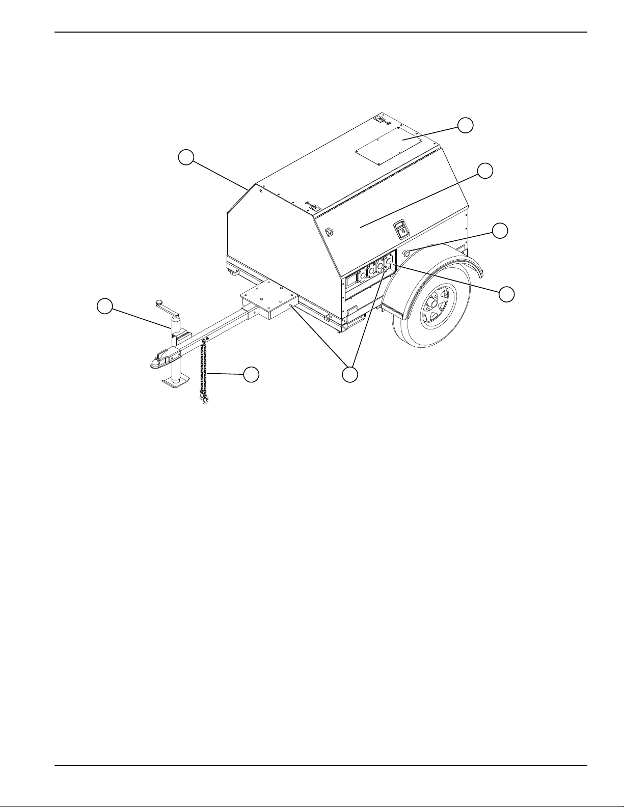
Component Locations
General Information
Figure 2-1. Component Locations
Table 2-1. Generator Components
Fuel Filler Location (under door)
A
Radiator Access Panel
B
Control Panel Locations (under door)
C
Emergency Stop Switch (on MLG8 units,
D
switch is located on front panel)
Receptacle Panel (not available on MLG8 units)
E
Ground Studs (2)
F
Safety Chains
G
Tongue Jack
H
Owner’s Manual for Mobile Generator 5
Page 10

General Information
003550
A
B
(000149)
DANGER
Risk of poisoning. Do not use mouth to
siphon coolant. Doing so will result in
death or serious injury.
(000154)
WARNING
Risk of burns. Do not open coolant system
until engine has completely cooled.
Doing so could result in serious injury.
(000165)
CAUTION
Do not use any chromate base rust inhibitor with
propylene glycol base antifreeze, boosters or
additives. Doing so will cause overheating.
Unit and Serial Number Locations
See Figure 2-2 to locate the unit ID tag (A) and Vehicle
Identification Number (VIN) tag (B). Important
information, such as the unit model number, serial
number, VIN and tire loading information is found on
these tags. Record the information from these tags so it
is available if the tags are lost or damaged. When
ordering parts or requesting assistance, you may be
asked to provide this information.
Figure 2-2. Unit and Serial Number Locations
Engine Oil Recommendations
To maintain the product warranty, the engine oil should
be serviced in accordance with the recommendations of
this manual.
The engine has been filled with factory engine oil of a
grade recommended by the engine supplier.
Use a high quality detergent oil with an appropriate
classification and viscosity for the engine type and
ambient temperature conditions. Consult your Generac
Mobile Products Authorized Dealer or the applicable
engine service manual for engine oil recommendations.
Coolant Recommendation
Consult your Generac Mobile Products Authorized
Dealer or the applicable engine service manual for
engine coolant recommendations. See table below for
mixtures:
Freezing Point °F (°C)
Water (% Volume) 60 50 40 30
Anitfreeze (% Volume) 40 50 60 70*
-12
(-24)
* Maximum freeze protection is at 70%.
-34
(-36)
-54
(-48)
-90
(-67)
6 Owner’s Manual for Mobile Generator
Page 11

Main Control Panels
120VAC120VAC
120VAC120VAC
240VAC240VAC
TURNTURN
MAINMAIN
BREAKERBREAKER
OFFOFF
120VAC120VAC
BREAKERBREAKER
120VAC120VAC
BREAKERBREAKER
240VAC240VAC
MAIN CIRCUITMAIN CIRCUIT
BREAKERBREAKER
240VAC240VAC
BREAKERBREAKER
GLOW PLUGGLOW PLUG
INDICATORINDICATOR
OFFOFF
RUNRUN
STARTSTART
GLOWGLOW
PLUGSPLUGS
NEUTRAL BONDED TO FRAMENEUTRAL BONDED TO FRAME
I
O
I
O
ON
ON
20 20
0
0 00 0
HOURS
ON
ON
TURN MAIN
BREAKER OFF
MAIN
BREAKER
240V
OFF
RUN
START
GLOW
PLUG
NEUTRAL BONDED TO FRAME
ON ON
0 0 00 0
HOURS
MLG8
MLG15 • MLG20 • MLG20ICAN
A
C
D
F
G
B
E
H
I
F
D
E
A
B
General Information
Figure 2-3. Control Panel Component Locations
Table 2-2. Control Panel Components
Circuit Breaker Indicator Light
A
Main Circuit Breaker
B
240VAC Circuit Breaker
C
Key Switch
D
Glow Plug Indicator
E
Engine Hour Meter
F
240V Twist-Lock Receptacle
G
120V GFCI Receptacles
H
120V Breaker
I
Owner’s Manual for Mobile Generator 7
Page 12

General Information
This page intentionally left blank.
8 Owner’s Manual for Mobile Generator
Page 13

Section 3 Operation
(000100a)
WARNING
Consult Manual. Read and understand manual
completely before using product. Failure to
completely understand manual and product
could result in death or serious injury.
Asphyxiation. Running engines produce
carbon monoxide, a colorless, odorless,
poisonous gas. Carbon monoxide, if not
avoided, will result in death or serious injury.
(000103)
DANGER
CAUTION
(000230)
Equipment Damage. Do not continuously
crank engine for more than ten seconds.
Doing so will lead to overdischarge of batteries
and starter seizure.
003552
A
Operation
Prestart Checklist
Before starting the unit, all items in the prestart checklist
must be completed.
• Verify all maintenance procedures are up to date.
For more information, see General Maintenance
and Basic Maintenance Schedule.
• Verify the unit is level.
• Verify there is no water inside, on, or near the unit.
Dry if needed.
• For grounding requirements, follow any local, state,
or National Electrical Code (NEC) guidelines.
• Verify the key switch is OFF (O).
• Verify all circuit breakers are OFF (O).
• Inspect all electrical cords; repair or replace any
that are cut, worn, or bare.
• Verify oil, coolant, and fuel levels are correct, per
the engine manufacturer manual.
• Verify battery connections are secure.
• Turn the battery disconnect switch ON, if equipped.
• Inspect the engine fan belt tension and condition.
• Inspect the engine fan guard.
• Inspect the engine exhaust system for loose or
rusted components.
• Verify the radiator and surrounding shroud are
clear of debris.
• Verify all covers are in place and secure.
• Verify the emergency stop switch is pulled out.
Starting the Unit
NOTE: If the engine was run out of fuel or the fuel tank
was drained, it may be necessary to bleed the fuel lines.
See the engine operator’s manual supplied with the unit.
1. Verify the main circuit breaker and individual circuit
breakers for each of the receptacles are OFF (O).
NOTE: When the red Turn Main Breaker Off light is
illuminated, the main circuit breaker must be turned to
OFF (O).
2. See Figure 3-1. Turn the key on the key switch to
GLOW PLUG (A) and hold the key in place for five
seconds, or until the glow plug indicator turns red.
Figure 3-1. Activate Glow Plug
Owner’s Manual for Mobile Generator 9
Page 14

Operation
003553
A
003554
A
WARNING
In case of an emergency, press the
emergency stop button to stop the engine
immediately. Failure to do so could result
in death or serious injury.
(000298)
CAUTION
(000246)
Equipment Damage. The emergency stop switch
is not to be used to power down the unit under
normal operating circumstances. Doing so will
result in equipment damage.
E
M
E
R
G
E
N
C
Y
S
T
O
P
002815
3. See Figure 3-2. As soon as it is glowing, turn the
key to START (A) and hold it until the engine
cranks and starts running.
Figure 3-2. Crank Engine to Start
4. See Figure 3-3. Release the key, it will move to
RUN (A).
Emergency Stop Switch
The unit is equipped with one emergency stop switch.
For location of the emergency stop switch, see
Component Locations. The switch can be accessed
and activated with all doors closed and locked.
Figure 3-3. Release Key
NOTE: For cold weather conditions, see the engine
operator’s manual for appropriate glow plug interval.
NOTE: If oil pressure is not obtained within 15 seconds
after the key is switched to RUN, the low oil automatic
shutdown will turn off the fuel supply, stopping the
engine. Check the oil level and turn the key to OFF to
reset the oil pressure timer before attempting to restart
the engine.
Activate the emergency stop switch by pushing the
button in until it locks down. This will trip the main circuit
breaker which will open the contact, disconnecting the
load to the connection lugs. This will also open the fuel
circuit, shutting down the engine. The emergency stop
fault will be displayed on the control panel. The switch
will remain closed until it is pulled out.
Figure 3-4. Emergency Stop Switch
Automatic Shutdown
5. Once the engine is running, allow it to reach
normal operating temperature before switching on
any loads.
10 Owner’s Manual for Mobile Generator
This unit is equipped with a low oil pressure and high
coolant temperature automatic shutdown system. This
system will automatically shut off the fuel supply to stop
the engine if oil pressure drops too low or the engine
exceeds normal operating temperature. Return the
switch to OFF to reset the unit after the cause of
shutdown has been determined.
Page 15

Voltage Regulator
003555
A
This unit is equipped with an electronic voltage regulator.
The voltage regulator controls the output of the generator
by regulating the current into the exciter field. The
regulator has three screwdriver adjustable
potentiometers that may be adjusted for voltage, stability
and voltage roll-off (U/F). The voltage regulator is
adjusted before shipment from the factory. Contact
Generac Mobile Products for additional information
before attempting to adjust the voltage regulator.
Derating for Altitude
All units are subject to derating for altitude and
temperature; this will reduce the available power for
operating tools and accessories connected to the
receptacles. Typical reductions in performance are 2-4%
for every 1000 ft (305 m) of elevation and 1% per 10ºF
(5.6ºC) increase in ambient air temperature over 72ºF
(22ºC).
Wet Stacking
The unit is powered by a diesel engine. Diesel engines
are susceptible to wet stacking if lightly loaded. Wet
stacking occurs when an engine is run at less than 30%
of its full load capacity, causing unburned fuel to
accumulate in the exhaust system. Wet stacking can be
detected by continuous black exhaust when the unit is
under a constant load. It can also cause fouling of
injectors and buildup on engine valves. Diesel engines
operate properly when applied loads are between 30%
and 100% capacity. Appropriate generator sizing is
determined by the anticipated load. If the unit is in a wet
stack condition, load the unit heavily for five hours or until
the exhaust is clear.
Receptacle Panel
This unit is equipped with a receptacle panel for running
accessories or tools from the generator. Power is
supplied to the receptacles any time the engine is
running and the main circuit breaker is switched to ON
(I). Each receptacle has an individual circuit breaker,
located inside the cabinet under a flip-up cover. Each
circuit breaker corresponds with the receptacle located
below it on the receptacle panel.
Should the main breaker, or any of the individual circuit
breakers trip, remove some of the load to the receptacles
before turning them back on.
NOTE: To ensure proper grounding, anytime the
generator is providing power to any equipment or load
panels that do not have a grounded plug, a ground wire
must be added between the equipment and the
grounding stud on the receptacle panel per the National
Electrical Code (NEC), state and local regulations.
Operation
Figure 3-5. Receptacle Panel Grounding Stud
A Receptacle Panel Grounding Stud
Shutting Down the Unit
Check with personnel using power supplied by the unit
and let them know the power is going to be turned off.
Verify the power shut down will not create any hazards by
accidentally turning off equipment that needs to be kept
on (pumps, compressors, lights, etc.). When you have
finished using the unit, proceed with shut down as
follows:
1. Remove all loads from the receptacles.
2. Switch the individual circuit breakers for each
receptacle to OFF (O).
3. Switch the main circuit breaker to OFF (O).
4. Turn the key switch to OFF.
NOTE: For extended storage time, disconnect the
battery. For extended storage requirements, see the
engine operator’s manual.
Towing the Unit
Once the engine is shut down, follow these steps to
prepare the unit for towing.
1. Verify the unit is OFF.
2. Use the jack to raise or lower the trailer onto the
hitch of the towing vehicle. Lock the hitch coupling
and attach the safety chains or cables to the
vehicle. Raise the jack foot completely.
3. Connect any trailer wiring to the tow vehicle. Check
for proper operation of the directional and brake
lights.
4. Verify all doors are properly latched.
5. Check for proper inflation of the trailer tires. Proper
inflation is specified on each tire.
Owner’s Manual for Mobile Generator 11
Page 16

Operation
WARNING
Personal injury. Excessive weight. Use only
appropriate lifting eyes and lifting equipment to
lift unit. Improper lifting techniques could result in
equipment damage, death or serious injury.
(000224)
003556
A
B
6. Check the wheel lugs. Tighten or replace any lugs
that are loose or missing. If a tire has been
removed for axle service or replaced, tighten the
lugs, in the order shown, to the following
specifications:
a. Start all lug nuts by hand.
b. First pass tighten to 20-25 ft-lbs
(27-33 Nm).
c. Second pass tighten to 50-60 ft-lbs
(67-81 Nm).
d. Third pass tighten to 90-120 ft-lbs
(122-162 Nm).
3. Use the forklift pockets with care. Approach the
unit as perpendicular as possible to avoid
damaging the unit. Verify any obstructions are
clear of the forklift tines before lifting.
Figure 3-7. Standard Forklift Pockets
002394
Figure 3-6. Lug Sequence
NOTE: After first road use, repeat tightening procedure.
Maximum recommended speed for highway towing is 45
mph (72 km/h). Recommended off-road towing speed is
not to exceed 10 mph (16 km/h).
Lifting the Unit
When lifting the unit, attach any slings, chains or hooks
directly to the central lift point.
1. Verify the equipment being used to lift the unit has
sufficient capacity. For approximate weights, see
the applicable product spec sheet.
2. Always remain aware of people and objects around
the unit while moving.
Figure 3-8. Optional Lift Structure
A Forklift Pockets
B Central Lift Point
12 Owner’s Manual for Mobile Generator
Page 17

Section 4 Maintenance
CAUTION
(000306)
Equipment Damage. Failure to perform a
daily inspection could result in damage to
the unit.
Maintenance
Emissions Information
For emissions information, see the OEM engine manual.
bar reaches the red section on the gauge (20 in.
O).
H
2
• Check wheel lugs. see Towing the Unit.
• Check coolant level daily. See the engine
Daily Walk Around Inspection
Look for conditions that could hinder performance or
safety, such as (but not limited to) oil/coolant/fuel
leakage, blocked vents, loose/missing hardware, and
electrical connections.
Visually inspect the fan belt for cracks, fraying,
stretching, and verify the belt is properly seated in the
pulley grooves. Replace the belt according to the
manufacturer’s recommendations.
General Maintenance
Poorly maintained equipment can become a safety
hazard. In order for the equipment to operate safely and
properly over a long period of time, periodic maintenance
and occasional repairs are necessary. Never perform
routine service (oil/filter changes, cleaning, etc.) unless
all electrical components are OFF. Before servicing the
unit, always follow the instructions listed below.
• Verify the key is removed.
• Verify the circuit breakers are OFF (O).
• Activate (push in) the emergency stop switch.
• Disconnect the negative (-) terminal on the battery.
operator’s manual for coolant recommendations
and proper mixture.
– Coolant is checked visually by inspecting the
level in the coolant overflow jug located near the
radiator.
– Normal operating level is between the FULL and
ADD markings on the overflow jug, also known
as the normal range.
– When engine is stopped and completely cool,
coolant may be added directly to the coolant
overflow jug.
• Check the oil level daily. See the engine operator’s
manual for the proper viscosity grade of oil,
including special operating conditions such as a
change in season or climate.
–Do not start the unit if the engine oil level is
below the ADD mark on the dipstick.
– Normal operating level is in the cross-hatch
pattern between the FULL and ADD markings on
the dipstick.
– Add oil only if the oil level is below the ADD mark
on the bottom of the cross-hatch pattern on the
dipstick.
– Do not overfill the crankcase.
• Check the fuel level.
NOTE: During the first 100 hours of operation, avoid
long periods of no load or sustained maximum load
operation. If the unit is to run for longer than five minutes
without a load, shut the engine OFF.
• Attach a “Do Not Start” sign to the control panel.
This will notify everyone that the unit is being
serviced and will reduce the chance of someone
inadvertently trying to start the unit.
• Do not wash the unit with a high pressure hose or
with any kind of power washer.
• Do not wash the engine block or fuel tank with a
power washer or steam cleaner. Water may enter
the cabinet and collect in the generator windings or
other electrical parts, causing damage. Water will
also pool on top of fuel tank and mix with any
environmentally hazardous fluids that may be
present, such as engine oil and coolant.
Basic Maintenance Schedule
See the original equipment manufacturer’s operating
manual for a complete list of maintenance requirements.
Failure to comply with the procedures as described in the
engine operator manual will nullify the warranty,
decrease performance and cause equipment damage or
premature equipment failure. Maintenance records may
be required to complete a warranty request.
• If the unit is stored outside, check for water inside
the cabinet and generator before each use. If wet,
dry the unit thoroughly before starting.
• Inspect condition of electrical cords. Do not use the
unit if insulation is cut or worn through.
• Verify the condition of the air filter by viewing the
level of the vacuum draw on the filter minder
gauge. Replace the air filter when the yellow center
Owner’s Manual for Mobile Generator 13
Page 18

Maintenance
Table 4-1. Basic Maintenance Schedule - MLG8
Item
Drain Water Separator
Inspect/Adjust Belt
Inspect/Clean Fuel Filter
Inspect/Replace Air Filter
Replace Engine Oil*
Check Radiator and Hose Clamps
Replace Engine Oil Filter*
Replace Fuel Filter
Clean Water Separator
Replace Fan Belt
Check/Clean Battery
Inspect/Adjust Valve Clearance
Replace Engine Coolant
Replace Radiator Hose Clamps
* Actual oil life and change intervals should be determined through oil sampling and analysis in extreme conditions.
As
Required
Every 200
Hours
Every 400
Hours
Every 500
Hours
Every 800
Hours
Every Two
Years
Table 4-2. Basic Maintenance Schedule - MLG15
Item
Drain Water Separator
Check/Replace Air Cleaner Element
Replace Engine Oil and Filter*
Inspect/Clean Solenoid Fuel Pump Filter
Inspect/Adjust Belt
Check Radiator and Hose Clamps
Replace Fuel Filter
Inspect/Adjust Valve Clearance
Check/Clean Battery
Replace Engine Coolant
Replace Radiator Hose Clamps
* Actual oil life and change intervals should be determined through oil sampling and analysis in extreme conditions.
As
Required
First 50
Hours
Every 250
Hours
Every 500
Hours
Every 24
Months
14 Owner’s Manual for Mobile Generator
Page 19

Table 4-3. Basic Maintenance Schedule - MLG20
Maintenance
Item
Drain Water Separator
Check Coolant Level
Inspect Belt
Replace Engine Oil*
Replace Engine Oil Filter*
Replace Fuel Filters
Adjust/Replace Belt
Replace Air Cleaner
Check/Clean Battery
Check/Adjust Valve Clearance
Replace Radiator Hose Clamps
Replace Engine Coolant
* Actual oil life and change intervals should be determined through oil sampling and analysis in extreme conditions.
As
Required
Every 250
Hours
Every 500
Hours
Every 1000
Hours
Every 12
Months
Owner’s Manual for Mobile Generator 15
Page 20

Maintenance
002823a
002824a
002825a
Jack Maintenance
The following procedures should be performed annually.
Side-Wind Models
•
The internal gearing and bushings of the jack must
be kept lubricated. Apply a small amount of
automotive grease to the internal gearing by
removing the jack cover, or if equipped, use a
needle nose applicator or standard grease gun on
the lubrication point found on the side of the jack
near the crank. Rotate the jack handle to distribute
the grease evenly.
• A lightweight oil must be applied to the handle unit
at both sides of the tube.
• If equipped, the axle bolt and nut assembly of the
caster wheel must also be lubricated with the same
lightweight oil.
Top-Wind Models
•
Apply a lightweight oil to the screw stem.
Figure 4-1. Lubrication Points
Trailer Wheel Bearings
The trailer axles are equipped with a grease fitting to
allow lubrication of the wheel bearings without the need
to disassemble the axle hub. To lubricate the axle
bearings, remove the small rubber plug on the grease
cap, attach a standard grease gun fitting to the grease
fitting and pump grease into the fitting until new grease is
visible around the nozzle of the grease gun. Use only a
high quality grease made specifically for lubrication of
wheel bearings. Wipe any excess grease from the hub
with a clean cloth and replace the rubber plug when
finished. The minimum recommended lubrication is every
12 months or 12,000 miles (19,312 km). More frequent
lubrication may be required under extremely dusty or
damp operating conditions.
16 Owner’s Manual for Mobile Generator
Page 21

Lower Radiator Hose Heater Option -
WARNING
Personal Injury. Do not modify the location of the
lower radiator hose heater. Improper use of hose
heater could result in personal injury or engine
damage.
(000339)
Use and Maintenance
The following points should be followed when operating a
unit equipped with a lower radiator hose heater.
• Verify the cooling system is full of the proper
mixture of water and engine coolant before each
heater use.
• The heater is designed for all-night operation,
however, 2-5 hours of heating just prior to starting
is usually sufficient for proper engine starting.
• The unit must be level to maintain proper
orientation of the heater while it is in operation.
• Use only an undamaged, outdoor rated, three-
prong grounded 120VAC extension cord with a
minimum amperage rating of 10A. Connect the
cord to a properly grounded 120VAC, GFCI
receptacle.
• Before starting the engine, unplug the extension
cord from the power, then unplug the heater
cordset from the extension cord.
Maintenance
Owner’s Manual for Mobile Generator 17
Page 22

Maintenance
This page intentionally left blank.
18 Owner’s Manual for Mobile Generator
Page 23

Wiring Diagrams and Service Log
Section 5 Wiring Diagrams and Service Log
AC Wiring Diagram W/3-30A, 1-50A Outlets
10
BLOCK 1
TERMINAL
RED
3
WHT
RED
2
WHT
1
GRN/YEL
GROUND
BONDED TO
BLK
RED
BLK
RED
BLK
RED
BLK
RED
50 AMP
CIRCUIT
50 AMP
CIRCUIT
30 AMP
CIRCUIT
BLK
RED
BREAKER
BLK
RED
BREAKER
BLK
RED
BREAKER
BLK
RED
50 AMP
TWIST LOCK
RECEPTACLE
50 AMP
TWIST LOCK
30 AMP
TWIST LOCK
WHT
GRN
WHT
GRN
RECEPTACLE
WHT
GRNGRN
WHT
7
8
9
BLK
4
5
6
BLK
MAIN
CIRCUIT
100 AMP
BREAKER
BLK
L1
N1
GEN
RED
L2
GRN
GROUND
BONDED TO
GRN
GROUND
BONDED TO
30 AMP
CIRCUIT
BREAKER
BLK
RED
20 AMP
CIRCUIT
20 AMP
CIRCUIT
BREAKER
BREAKER
30 AMP
TWIST LOCK
RECEPTACLE RECEPTACLE
BLK
WHT
G.F.I.
20 AMP
RED
WHT
G.F.I.
20 AMP
RECEPT. RECEPT.
90212_A_08.27.12
GRN
GRN
Owner’s Manual for Mobile Generator 19
Page 24

Wiring Diagrams and Service Log
AC Wiring Panel Options
BLK
BLK
RED
RED
50 AMP
TO MAIN BREAKER
TO NEUTRAL
TO GROUND
TO MAIN BREAKER
BREAKER
CIRCUIT
BLK
RED
20 AMP
BREAKER
CIRCUIT
BLK
RED
20 AMP
BREAKER
CIRCUIT
BLK
RED
WHT
GRN
BLK
RED RED
20 AMP
BREAKER
CIRCUIT
BLK
RED
BLK
RED
50 AMP
240 VOLT
RECEPTACLE
20 AMP
20 AMP
CIRCUIT
BREAKER
CB CB
CIRCUIT
BREAKER
TWIST-LOCK
GRN GRN
20 AMP
240 VOLT
TWIST LOCK
RECEPTACLE
GRN
20 AMP
240 VOLT
TWIST LOCK
RECEPTACLE
GRN
20 AMP
240 VOLT
TWIST LOCK
RECEPTACLE
WHT
BLK
GRN
G.F.I
20 AMP
OUTLET
RED
GRN
G.F.I
20 AMP
OUTLET
BLK
RED
BLK
RED
BLK
90319_ORG_07.06.11
50 AMP
CIRCUIT
30 AMP
CIRCUIT
30 AMP
CIRCUIT
BLK
REDRED
BREAKER
BLK
REDRED
BREAKER
BLK
RED
BREAKER
BLKBLK
RED
BLK
BLK
BLK
RED
RED
BLK
WHT
WHT
WHT
WHT
TO MAIN BREAKER
2x5-20R, 3xL6-20R, 1x50A
WHT
TO NEUTRAL
TO GROUND
BLK
RED
WHT
GRN
BLK
RED
RED
30 AMP
CIRCUIT
BREAKER
BLK
BLK
RED
RED
30 AMP
CIRCUIT
BREAKER
BLK
BLK
RED
RED
30 AMP
CIRCUIT
BREAKER
BLK
BLK
RED
RED
30 AMP
CIRCUIT
BREAKER
240 VOLT
240 VOLT
240 VOLT
240 VOLT
30 AMP
TWIST-LOCK
30 AMP
TWIST-LOCK
30 AMP
TWIST-LOCK
30 AMP
TWIST-LOCK
WHT
GRN
RECEPTACLE
WHT
GRN
RECEPTACLE
WHT
GRN
RECEPTACLE
WHT
GRN
RECEPTACLE
2x5-20R, 4xL14-30R
WHT
WHT
BLK
BLK
20 AMP
CIRCUIT
BREAKER
RED
CB CB
20 AMP
CIRCUIT
BREAKER
GRN
G.F.I
20 AMP
OUTLET
RED
GRN
G.F.I
20 AMP
OUTLET
90321_ORG_07.06.11
240 VOLT
240 VOLT
240 VOLT
50 AMP
TWIST LOCK
30 AMP
TWIST LOCK
30 AMP
TWIST LOCK
RECEPTACLE
RECEPTACLE
RECEPTACLE
GRN GRN GRN
WHT
WHT
WHT
WHT
TO MAIN BREAKER
BLK
RED
BLK BLK
50 AMP
BREAKER
CIRCUIT
BLK BLK
30 AMP
BREAKER
CIRCUIT
BLK
RED
30 AMP
BREAKER
CIRCUIT
RED RED
REDRED
240 VOLT
REDRED
240 VOLT
BLK
RED
240 VOLT
BLKBLK
50 AMP
TWIST-LOCK
30 AMP
TWIST LOCK
30 AMP
TWIST LOCK
WHT
RECEPTACLE
WHT
GRN GRN
RECEPTACLE
WHT
GRN
RECEPTACLE
WHT
GRN
30 AMP
240 VOLT
TWIST LOCK
RECEPTACLE
WHT
WHT
GRN
G.F.I
20 AMP
OUTLET
RED
GRN
G.F.I
20 AMP
OUTLET
90320_ORG_07.06.11
2x5-20R, 3xL14-30R, 1x50A
TO NEUTRAL
TO GROUND
WHT
30 AMP
BREAKER
CIRCUIT
GRN
BLK
BLK
CB
20 AMP
CIRCUIT
BREAKER
RED
RED
CB
20 AMP
CIRCUIT
BREAKER
240 VOLT
30 AMP
TWIST LOCK
WHT
G.F.I
20 AMP
G.F.I
20 AMP
RECEPTACLE
OUTLET
OUTLET
GRN
GRN
GRN
WHT
2x5-20R, 3xL6-30R, 1x50A
TO NEUTRAL
TO GROUND
WHT
GRN
30 AMP
BREAKER
CIRCUIT
BLK BLK
RED
CB
20 AMP
CIRCUIT
CB
20 AMP
CIRCUIT
BREAKER
BREAKER
90318_ORG_07.06.11
20 Owner’s Manual for Mobile Generator
Page 25

AC Wiring Diagram - MLG 8
MAIN
CIRCUIT
BREAKER
40 AMP
2 POLE
L1
GRN
GEN
L2
RED
RED
BLK
BLK
RED
WHT
WHT
WHT
TERMINAL
BLOCK 1
10
9
8
7
6
5
4
3
2
1
Wiring Diagrams and Service Log
RED
240 VOLT
30 AMP
CIRCUIT
BREAKER
240 VOLT
30 AMP
TWIST LOCK
RECEPTACLE
20 AMP
G.F.I.
OUTLET
GRN
20 AMP
G.F.I.
OUTLET
GRN
GRN/YEL
CB
20 AMP
CIRUIT
BREAKER
CB
20 AMP
CIRUIT
BREAKER
90732_A_07.25.16
Owner’s Manual for Mobile Generator 21
Page 26

Wiring Diagrams and Service Log
DC Wiring Diagram - MLG 8 and MLG15
RED
RED
BLK
MAIN
CIRCUIT
BREAKER
40 AMP
2 POLE
GRN
L1
GEN
L2
BLK
RED
WHT
WHT
WHT
TERMINAL
BLOCK 1
10
9
8
7
6
5
4
3
2
1
RED
240 VOLT
30 AMP
CIRCUIT
BREAKER
240 VOLT
30 AMP
TWIST LOCK
RECEPTACLE
20 AMP
G.F.I.
OUTLET
GRN
20 AMP
G.F.I.
OUTLET
GRN
GRN/YEL
CB
20 AMP
CIRUIT
BREAKER
CB
20 AMP
CIRUIT
BREAKER
90732_A_07.25.16
22 Owner’s Manual for Mobile Generator
Page 27

DC Wiring Diagram - MLG 20
90733_A_07.25.16
WARNING
LIGHT
“TURN MAIN
BREAKER OFF”
BLK
NO
NC
C
MAIN BREAKER
AUX SWITCH
GLOW PLUGS
BLU
B TERM
R TERM
SOLENOID
RED (HOLD)
WHT (PULL)
BLK (COM)
ORN
BRN
BLK
CONTROL
RESISTANCE
BLU
BLU
DOME
LIGHT
R1
R2
B
BR
ACC
C
STARTER SWITCH
GRN
BLU
RED
GRN
RED
BLK
B
B
S
STARTER
RED
BATTERY 12V
EMERGENCY
STOP
SWITCH
1
4
3
2
N.C.
N.C.
VIO/WHT
VIO
RED
TIME
DELAY
RELAY
1
2
3
5
6
OVERHEAT
WARNING
SWITCH
(NORMAL
OPEN TYPE)
PUR
PNK
OIL
PRESSURE
WARNING
SWITCH
(NORMAL
CLOSED TYPE)
FUSE
SWITCH
RED
10 AMP
CIRCUIT
BREAKER
BLK
HOUR
FUEL
PUMP
RED
RED
BLK
BLK
Wiring Diagrams and Service Log
Owner’s Manual for Mobile Generator 23
Page 28

Wiring Diagrams and Service Log
GN
YL
BN
WT
MARKER
LAMP
AMBER
TRAILER
PLUG
RIGHT
TAIL/TURN
LAMP
LAMP
PLATE
LICENSE
MARKER
LAMP
RED
BK
BK
BK
BK
RD
WT
BK
SPLICE
SPLICE
SPADE
SPADE
LAMP
TAIL/TURN
LEFT
RDWTBK
SPADE
YL
BN
WT
SPADE
SPADE
WT
BK
BN
WT
SPLICE
GN
RING
MARKER
LAMP
AMBER
MARKER
LAMP
RED
BK
BK
BK
BK
SPLICE
SPLICE
SPADE
SPADE
BN
WT
WT
WT
BN
BN
90341_B_12.20.13
Trailer Harness
24 Owner’s Manual for Mobile Generator
Page 29

Wiring Diagrams and Service Log
OIL GRADE: _____________________________________ BRAND: __________________________________
COOLANT MIXTURE: _____________________________ BRAND: __________________________________
__________________________________________________________________________________________
__________________________________________________________________________________________
__________________________________________________________________________________________
__________________________________________________________________________________________
__________________________________________________________________________________________
__________________________________________________________________________________________
__________________________________________________________________________________________
__________________________________________________________________________________________
__________________________________________________________________________________________
Date
Hours to
Service
Oil Level
Coolant
Level
Date
Hours to
Service
Oil Level
Coolant
Level
Service Log
Owner’s Manual for Mobile Generator 25
Page 30

Wiring Diagrams and Service Log
This page intentionally left blank.
26 Owner’s Manual for Mobile Generator
Page 31

Page 32

Part No. 10289 Rev. M 09/09/16
©2016 Generac Mobile Products LLC. All rights reserved
Specifications are subject to change without notice.
No reproduction allowed in any form without prior written
consent from Generac Mobile Products LLC.
Generac Mobile Products
215 Power Drive, Berlin, WI 54923
GeneracMobileProducts.com │800-926-9768 │920-361-4442
 Loading...