

Page 1
GASEOUS GENERATOR
Discount-Equipment.com
MGG155 • MGG210
OPERATING MANUAL
00620
www.discount-equipment.com
35319 C 05/16
Page 2

Discount-Equipment.com is your online resource for commercial and industrial
Discount-Equipment.com
quality parts and equipment sales.
Locations:
Florida (West Palm Beach): 561-964-4949
Outside Florida TOLL FREE: 877-690-3101
Need parts? Check out our website at www.discount-equipment.com
Can’t find what you need?
Click on this link: http://www.discount-equipment.com/category/5443-parts/ and fill out
the request form.
Please have the machine model and serial number available in order to help us get
you the correct parts. One of our experienced staff members will get back to you with
a quote for the right part that your machine needs.
We sell worldwide for the br
Diamond
Chicago Pneumatic, Allmand Brothers, Essick, Miller Spreader, Skyjack, Lull, Skytrak,
Tsurumi, Husquvarna/Target, Whiteman-Concrete/Mortar, Stow-Concrete/Mortar, Baldor,
Wacker, Sakai, Snorkel, Upright, Mi-T-M, Sullair, Neal, Basic, Dynapac, MBW, Weber,
Bartell, Bennar Newman, Haulotte, Ditch Runner, Blaw-Knox, Himoinsa, Best, Buddy,
Crown, Edco, Wyco, Bomag, Laymor, Terremite, Barreto, EZ Trench, Takeuchi, Basic, Bil-
Jax, Curtis, Gehl, Heli, Honda, ICS/PowerGrit, Puckett, Waldon, ASV, IHI, Partner, Imer,
Clipper, MMD, Koshin, Rice, Gorman Rupp, CH&E, Cat Pumps, Comet, General Pump,
Giant,AMida, Coleman, NAC, Gradall, Square Shooter, Kent, Stanley, Tamco, Toku, Hatz,
Kohler, Robin, Wisconsin, Northrock, Oztec, Toker TK, Rol-Air, Small Line, Wanco, Yanmar
Products, Magnum, Airman, Mustang, Power Blanket, Nifty Lift, Atlas Copco,
ands: Genie, Terex, JLG, MultiQuip, Mayco, Toro/Stone,
Page 3
WARNING
Discount-Equipment.com
CALIFORNIA PROPOSITION 65 WARNING: Engine exhaust and some of its constituents
are known to the state of California to cause cancer, birth defects, and other reproduc-
tive harm. (000004)
WARNING
CALIFORNIA PROPOSITION 65 WARNING: This product contains or emits chemicals
known to the state of California to cause cancer, birth defects, and other reproductive
harm. (000005)
WARNING
ENVIRONMENTAL HAZARD: Always recycle batteries at an official recycling center in
accordance with all local law and regulations. Failure to do so could result in environ-
mental damage, death or serious injury. (000228)
ii
Page 4

Introduction
Discount-Equipment.com
This manual provides information and procedures to safely operate and maintain the Generac Mobile Products unit.
For your own safety and protection from physical injury, carefully read, understand, and observe the safety instructions
described in this manual. Keep a copy of this manual with the unit at all times. Additional copies are available from
Generac Mobile Products. The information contained in this manual was based on machines in production at the
time of publication. Generac Mobile Products reserves the right to change any portion of this information without
notice.
Read all of the manuals included with the unit. Each manual details specific information regarding items such as
setup, use and service requirements. An engine operator’s manual provides detailed operation and maintenance
procedures for the engine. Additional copies of the engine operator’s manual are available from the engine
manufacturer.
DO NOT MODIFY or use this equipment for any application other than for which it was designed.
Only a trained and licensed electrician should perform wiring and connections to unit. Wiring must be in compliance
with National Electrical Code (NEC), state and local regulations, and Occupational Safety and Health Administration
(OSHA) guidelines.
Engine Make:__________________________________________
Engine Serial Number:___________________________________
Engine Model Number: __________________________________
Generator Make: _______________________________________
Generator Model Number: ________________________________
Generator Serial Number: ________________________________
Unit Model Number:_____________________________________
Unit Serial Number: _____________________________________
Dealer Name:__________________________________________
Dealer Phone Number: __________________________________
iii
Page 5

Table of Contents
Discount-Equipment.com
Section 1 - Safety
Safety Notes ....................................................................................................................................... 1
Operating Safety................................................................................................................................. 1
Engine Safety ..................................................................................................................................... 2
Service Safety .................................................................................................................................... 2
Towing Safety.....................................................................................................................................3
Reporting Trailer Safety Defects ........................................................................................................ 3
Section 2 - General Information
Specifications ..................................................................................................................................... 5
Unit Dimensions .................................................................................................................... 6
Engine Oil Recommendations ............................................................................................... 6
Coolant Recommendation ..................................................................................................... 7
Unit Serial Number Locations.............................................................................................................7
Component Locations......................................................................................................................... 8
Unit Set Up ....................................................................................................................................... 14
Well Site Approval ............................................................................................................... 14
Fuel Connections................................................................................................................. 14
LP Liquid Connections (Liquid Withdrawal System)............................................................ 17
Valve and Fitting Pipe Equivalents ...................................................................................... 19
Electrical Connections ......................................................................................................... 19
Dual Fuel System ............................................................................................................................. 20
Natural Gas (Well Gas) Fuel System .................................................................................. 20
LP Liquid Withdrawal Fuel System...................................................................................... 20
DC Fuses.......................................................................................................................................... 20
Generator and Load Compatibility....................................................................................................20
Engine/Generator Protective Devices .............................................................................................. 21
Digital Controller ............................................................................................................................... 21
Setting the Clock ................................................................................................................. 22
Section 3 - Operation
Prestart Checklist ............................................................................................................................. 23
Manually Starting the Unit ................................................................................................................ 23
Natural Gas (Well Gas) Start Up .........................................................................................23
LP Liquid Start Up ............................................................................................................... 24
Auto (Remote) Starting the Unit ....................................................................................................... 24
Parallel Setup and Operation ........................................................................................................... 24
Operation Checks.............................................................................................................................25
Overcrank Shutdown ........................................................................................................................ 25
Derating for Altitude..........................................................................................................................26
Generator Output Connections......................................................................................................... 26
Customer Convenience Receptacles ............................................................................................... 27
Main Circuit Breaker ......................................................................................................................... 28
Frame Ground Connection .................................................................................................. 28
Battery Disconnect Switch................................................................................................... 28
Shutting Down the Unit.....................................................................................................................28
Emergency Stop Switch ................................................................................................................... 29
Towing the Trailer.............................................................................................................................29
Section 4 - Maintenance
Emissions ......................................................................................................................................... 31
Maintenance Tasks .......................................................................................................................... 31
Daily Walk Around Inspection.............................................................................................. 31
Check Fuel System ............................................................................................................. 31
Check Engine Fluids............................................................................................................ 31
Changing the Oil.................................................................................................................. 32
v
Page 6

Adding Coolant .................................................................................................................... 33
Discount-Equipment.com
Integrated Electronic Pressure Regulator (IEPR) Maintenance and Inspection.................. 33
Checking/Draining Oil Build-Up in the Vaporizer Regulator ................................................34
Maintenance Schedule ..................................................................................................................... 34
Battery Inspection................................................................................................................ 36
Battery Replacement ........................................................................................................... 37
Other Maintenance Checks ................................................................................................. 38
Jack Maintenance............................................................................................................................. 39
Side-Wind Models ............................................................................................................... 39
Top-Wind Models ................................................................................................................ 39
Trailer Wheel Bearings ..................................................................................................................... 39
Section 5 - Troubleshooting
Problems and Solutions....................................................................................................... 41
Section 6 - Wiring Diagrams
AC Wiring - MGG155 (120V GCB) ...................................................................................................53
AC Wiring - MGG210 (120V GCB) ...................................................................................................54
AC Wiring - MGG155 (24V GCB) ..................................................................................................... 55
AC Wiring - MGG210 (24V GCB) ..................................................................................................... 56
DC Wiring - MGG155 (120V GCB)...................................................................................................57
DC Wiring - MGG210 (120V GCB)...................................................................................................58
DC Wiring - MGG155 (24V GCB).....................................................................................................59
DC Wiring - MGG210 (24V GCB).....................................................................................................60
CAN Parallel Communication Connection - MGG155 and MGG210 ............................................... 61
vi
Page 7

SAFETY NOTES
Discount-Equipment.com
This is the safety alert symbol. It is used to alert you to potential personal injury hazards. Obey all safety
messages that follow this symbol to avoid possible injury or death.
This manual contains DANGERS, WARNINGS, CAUTIONS, NOTICES and NOTES which must be
followed to prevent the possibility of improper service, damage to the equipment, personal injury or death.
The following formatting options will apply when calling the readers attention to the DANGERS, WARNINGS, CAUTIONS, NOTICES and NOTES.
INDICATES A HAZARDOUS SITUATION WHICH, IF NOT AVOIDED, WILL RESULT IN
Indicates a hazardous situation which, if not avoided, could result in death or serious
Indicates a hazardous situation which, if not avoided, could result in minor or moderate
Section 1 - Safety
DANGER
DEATH OR SERIOUS INJURY. (000001)
WARNING
injury. (000002)
CAUTION
injury. (000003)
Indicates a hazardous situation which, if not avoided, could result in property or equipment
damage.
Note: Notes contain additional information important to a procedure and will be found within the regular text body
of this manual.
OPERATING SAFETY
Before using the unit, be sure you read and understand all of the instructions. This equipment was
designed for specific applications; DO NOT modify or use this equipment for any application other than
which it was designed for. Equipment operated improperly or by untrained personnel can be dangerous.
Read the operating instructions and familiarize yourself with the location and proper use of all instruments
and controls. Inexperienced operators should receive instruction from someone familiar with the equipment
before being allowed to operate or set up the unit. The following points should be practiced at all times:
• The area immediately surrounding the unit should be dry, clean, and free of debris.
• Position and operate the unit on a firm, level surface.
• DO NOT start a unit in need of repair.
• If the unit is equipped with a frame grounding stud, follow any local, state, and National Electrical
Code (NEC) guidelines when connecting.
• DO NOT operate the unit on a combustible surface.
• DO NOT operate a unit while tired, distracted, or under the influence of drugs or alcohol.
• Keep all body parts, clothing and other loose items away from moving parts.
• All fuel types are potentially FLAMMABLE and/or EXPLOSIVE and should be handled with care.
Comply with all laws regulating the storage and handling of fuels. Inspect the unit’s fuel system
frequently and correct any leaks immediately. Fuel supply lines must be properly installed, purged,
and leak tested according to applicable fuel-gas codes before placing the equipment into service.
35319 C MGG155/210 Operating Manual 1
Page 8
Safety
Discount-Equipment.com
• DO NOT smoke around the unit.
• Shut the engine down if any of the following conditions exist during operation:
1. Noticeable change in engine speed.
2. Loss of electrical output.
3. Equipment connected to the unit overheats.
4. Sparking occurs.
5. Engine misfires or there is excessive engine/generator vibration.
6. Protective covers are loose or missing.
7. If the ambient air temperature is above 120°F (49°C).
ENGINE SAFETY
Internal combustion engines present special hazards during operation and fueling. Failure to follow the
safety guidelines described below could result in severe injury or death. Read and follow all safety warnings
described in the engine operator's manual. A copy of this manual was supplied with the unit when it was
shipped from the factory.
• DO NOT run engine indoors or in an area with poor ventilation unless exhaust hoses are used. Engine
exhaust contains carbon monoxide, a deadly, odorless and colorless gas which, if inhaled, can cause
nausea, fainting or death. Verify engine exhaust cannot seep into closed rooms or ventilation
equipment.
• DO NOT touch or lean against hot exhaust pipes or engine components.
• DO NOT clean air filter with gasoline or other types of low flash point solvents.
• DO NOT operate the unit without a functional exhaust system.
• Prolonged exposure to sound levels in excess of 85 dB(A) can cause permanent hearing loss. Wear
hearing protection when working around a running engine.
• Batteries contain sulfuric acid which can cause severe injury or death. Sulfuric acid can cause eye
damage, burn flesh or eat holes in clothing. Protective eye wear and clothing are necessary when
working on or around the battery. Always disconnect the negative (-) battery cable from the
corresponding terminal before performing any service on the engine or other components.
• DO NOT remove the radiator cap while the engine is hot.
• Keep area around exhaust pipes and air ducts free of debris to reduce the chance of an accidental fire.
SERVICE SAFETY
All service work must be performed by qualified personnel who are familiar with the equipment. Only a
qualified electrician should troubleshoot or repair electrical problems occurring in this equipment. Follow the safety guidelines described below to prevent hazardous situations which could result in severe
injury or death.
• DO NOT wash the unit with high pressure hoses, power washers, or steam cleaners. Water may
collect in the unit, causing damage to electrical parts.
• ALWAYS use extreme caution when servicing this unit in damp conditions. Do not service the unit if
your skin or clothing is wet. Do not allow water to collect around the base of the unit.
• Replace all missing and hard to read decals. Decals provide important operating instructions and
warn of dangers and hazards.
• ALWAYS turn the battery disconnect switch to the OFF position before performing any service on the
engine, generator, or any other components. Remove the negative (-) battery cable from the
corresponding terminal if the unit is to be stored or transported.
2 MGG155/210 Operating Manual 35319 C
Page 9

• DO NOT start the unit under load. The main circuit breaker must be in the open position (press the
Discount-Equipment.com
right I/O button on the controller) when starting the unit.
TOWING SAFETY
Towing a trailer requires care. Both the trailer and vehicle must be in good condition and securely fastened
to each other to reduce the possibility of an accident. Some states require that large trailers be registered
and licensed. Contact your local Department of Transportation office to check on license requirements for
your particular unit.
• Verify the hitch and coupling on the towing vehicle are rated equal to, or greater than, the trailer's
Gross Vehicle Weight Rating (GVWR).
• Check trailer tires for wear and proper inflation.
• DO NOT tow trailer using defective parts. Inspect the hitch and coupling for wear or damage.
• Verify the trailer hitch and the coupling are compatible and the coupling is securely fastened to the
vehicle.
• Verify the directional and brake lights on the trailer are connected and working properly.
• See Towing the Trailer. Verify wheel lug nuts are present and tightened to the specified torque.
• Maximum recommended speed for highway towing is 45 mph (72 km/h). Recommended off-road
towing speed is 10 mph (16 km/h).
Safety
• When towing, maintain extra space between vehicles and avoid soft shoulders, curbs and sudden
lane changes. Practice turning, stopping and backing up in an area away from heavy traffic prior to
transporting unit.
• Wipe the coupler clean and apply fresh grease each time the trailer is towed to eliminate squeaking.
• Connect safety chains in a crossing pattern under the tongue and ATTACH THE BREAKAWAY
CABLE TO THE REAR BUMPER OF THE TOWING VEHICLE. Do not attach the cable to the trailer
hitch.
• The trailer is equipped with hydraulic or electric surge brakes. Verify proper operation of the brakes
by braking the vehicle at a slow speed before entering traffic. Both the trailer and the vehicle should
brake smoothly. If the trailer seems to be pushing, check the level in the brake fluid reservoir, if
equipped.
REPORTING TRAILER SAFETY DEFECTS
If you believe your trailer has a defect which could cause a crash or could cause injury or death, you should immediately
inform the National Highway Traffic Safety Administration (NHTSA) in addition to notifying Generac Mobile Products
LLC.
If NHTSA receives similar complaints, it may open an investigation; and if it finds that a safety defect exists in a group
of vehicles, it may order a recall and remedy campaign. However, NHTSA cannot become involved in an individual
problem between you, your Independent Authorized Service Dealer, or Generac Mobile Products LLC.
To contact NHTSA, you may either call the Auto Safety Hotline toll-free at 1-888-327-4236 (TTY:1-800-424-9153),
go to http://www.safercar.gov; or write to:
Administrator
NHTSA
1200 New Jersey Avenue S.E.
Washington, DC 20590
You can also obtain other information about motor vehicle safety from http://www.safercar.gov.
35319 C MGG155/210 Operating Manual 3
Page 10
Safety
Discount-Equipment.com
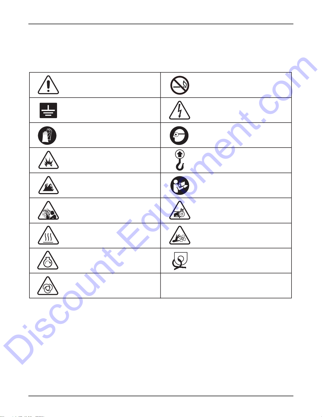
SAFETY SYMBOL SUMMARY
The safety and operating decals affixed to the unit provide important instructions and warn of dangers and hazards.
Replace any missing or hard-to-read decals and use care when washing or cleaning the unit. Decal placement and
part numbers can be found in the online parts manual at www.generacmobileproducts.com. Below is a summary of
the intended meanings for the symbols used on the decals.
Safety alert symbol; used to alert
you to potential personal
injury hazards.
No open flames.
Unit electrical ground.
Wear protective gloves.
Explosion hazard.
Fire hazard.
Burn/scald hazard;
pressurized steam.
Hot surface(s) nearby.
Dangerous voltage may be
present.
Use protective eyewear.
Lift here only.
Read and understand the
supplied operator’s manual
before operating unit.
Belt/entanglement hazard; keep
body parts clear of this area.
Fan hazard; keep body parts
clear of this area.
Engine starting/remote starting point.
Engine can start automatically.
4 MGG155/210 Operating Manual 35319 C
Anchor/tie down point.
00844
Page 11

Section 2 - General Information
Discount-Equipment.com
SPECIFICATIONS
GENERAC MODEL MGG155 MGG210
Engine
Make/Brand............................................................................. PSI ..........................................PSI
Model ......................................................................................D081TIC..................................D111TIC
Induction System ....................................................................Turbo CAC ..............................Turbo CAC
Horsepower - Prime - Natural Gas hp (kW) ..........................239 (178) ................................. 302 (225)
Horsepower - Standby - LP Liquid hp (kW) ...........................200 (149) .................................272 (203)
Operating Speed rpm .............................................................1800 ........................................ 1800
Displacement in
Cylinders - qty .........................................................................6 .............................................. 6
Spark plug gap in (mm)..........................................................0.015 (.4) .................................0.015 (.4)
Fuel Consumption (NG) - 100% load ft
Fuel Consumption (NG) - 75% load ft
Fuel Consumption (NG) - 50% load ft
Fuel Consumption (LP) - 100% load gal/hr (L/hr)..................15.4 (58.3) ...............................19.2 (72.7)
Fuel Consumption (LP) - 75% load gal/hr (L/hr)....................11.8 (44.7) ...............................14.7 (55.6)
Fuel Consumption (LP) - 50% load gal/hr (L/hr)....................8.3 (31.4) .................................10.2 (38.6)
Battery Type - Group Number .................................................8D............................................8D
Battery Voltage (quantity per unit)...........................................12V (2) .................................... 12V (2)
Battery Voltage (series connection) ........................................24V..........................................24V
Battery Rating .........................................................................1100CCA................................. 1100CCA
3
(L) ..............................................................494 (8.1) ..................................673 (11.0)
3
/hr (m3/hr) ..............1092 (30.9) .............................. 1431 (40.5)
3
/hr (m3/hr) ................858 (24.3) ................................ 1112 (31.5)
3
/hr (m3/hr) ................625 (17.7) ................................ 794 (22.5)
Generator
Make/Brand............................................................................. Stamford..................................Stamford
Model ......................................................................................UCI274E-311...........................UCI274G-311
Type, Insulation....................................................................... Brushless, H............................Brushless, H
See the data plate on the generator for rated watts, amperes, frequency, voltage, phase and other important information.
Generator Set (Engine/Generator)
3Ø - Continuous - Natural Gas kW (kVA) ..............................100 (125) ................................. 137 (171)
3Ø - Standby - LP Liquid kW (kVA) ........................................ 108 (135).................................139 (173)
Amps - 3Ø Continuous - Natural Gas (480V/277) A ...............150 .........................................206
Amps - 3Ø Standby - Natural Gas (480V/277) A ....................214 .........................................278
Amps - 3Ø Standby - LP Liquid (480V/277) A .......................162 .......................................... 209
Frequency Hz .........................................................................60 ............................................ 60
Power Factor........................................................................... 0.8 ..........................................0.8
AC Distribution
Circuit Breaker Size A............................................................. 200 ..........................................400
Voltage Regulation..................................................................Digital ......................................Digital
Voltages Available 3Ø .............................................................480 (277/480)..........................480 (277/480)
Capacities
Coolant (incl. engine) qt (L) ...................................................20 (18.9)..................................22 (20.8)
Oil (incl. filter) qt (L) ...............................................................7.2 (6.81).................................7.6 (7.19)
Weights
Operating Weight, Skid Mounted lbs (kg) .............................7245 (3286).............................7290 (3307)
Operating Weight, Trailer Mounted lbs (kg) ..........................9645 (4375) .............................9890 (4486)
Trailer
Number of Axles......................................................................2 ..............................................2
Capacity - Axle Rating lbs (kg) ............................................... 7000 (3175).............................7000 (3175)
Tire Size in .............................................................................16 ............................................ 16
Brakes - Standard ...................................................................Electric ....................................Electric
Hitch - Standard ......................................................................3" lunette ring ..........................3" lunette ring
Maximum Tire Pressure psi ...................................................80 ............................................80
Specifications are subject to change without notice.
35319 C MGG155/210 Operating Manual 5
Page 12
General Information
Discount-Equipment.com
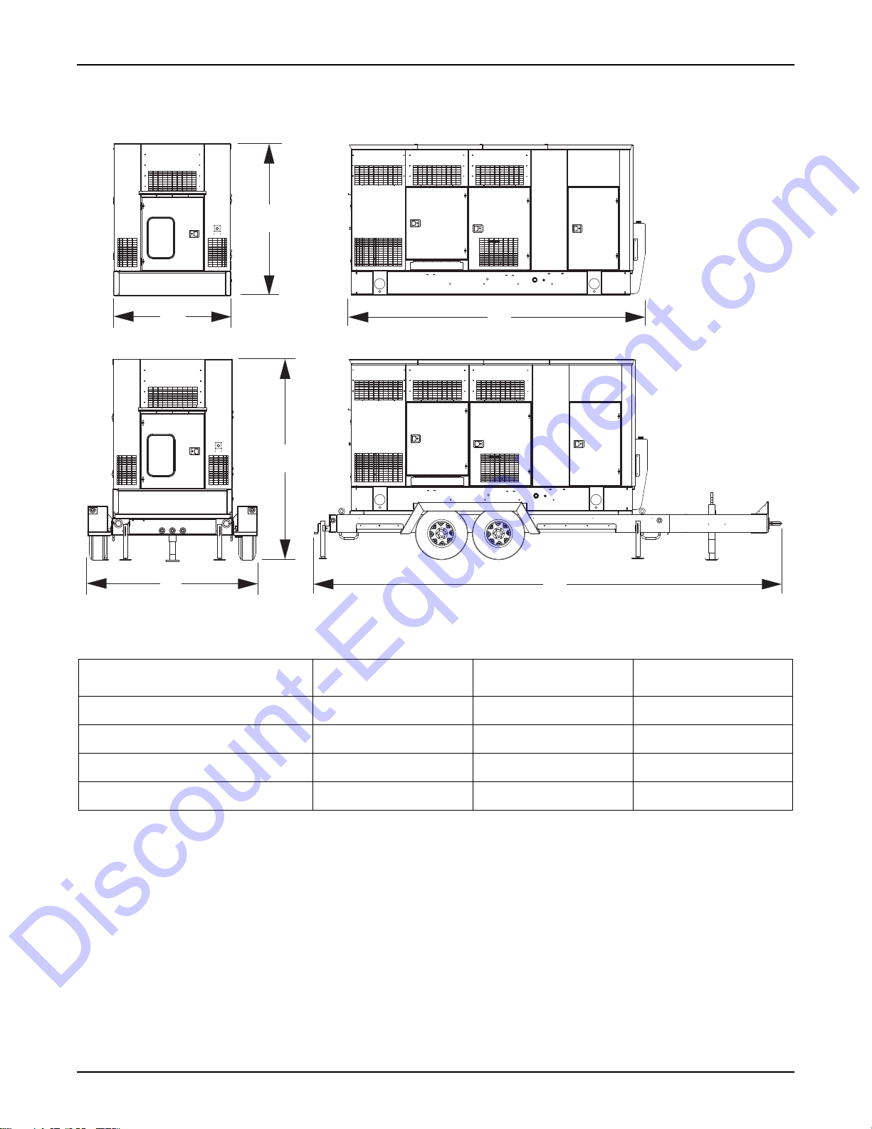
Unit Dimensions
B
A
B
A
Figure 1 - Unit Dimensions
ABC
MGG155 - Skid Mounted 66 in. (1.67 m) 92 in. (2.33 m) 169 in. (4.29 m)
C
C
02020
MGG155 - Trailer Mounted 102 in. (2.59 m) 124 in. (3.15 m) 269 in. (6.83 m)
MGG210 - Skid Mounted 66 in. (1.67 m) 92 in. (2.33 m) 201 in. (5.10 m)
MGG210 - Trailer Mounted 102 in. (2.59 m) 124 in. (3.15 m) 269 in. (6.83 m)
Specifications are subject to change without notice.
Engine Oil Recommendations
To maintain the product warranty, the engine oil should be serviced in accordance with the recommendations of this
manual. For your convenience, Generac Maintenance Kits are available that include engine oil, oil filter, air filter,
spark plug(s), a shop towel and funnel. These kits can be obtained from an Independent Authorized Service Dealer
(IASD).
The engine has been filled with factory engine oil of a grade recommended by the engine supplier. The manufacturer
recommends an initial oil and filter change after the first 50 hours (or first three months) of service operation. Use a
high quality detergent oil with an appropriate classification and viscosity for the engine type and ambient temperature
conditions. See Specifications for oil capacity.
6 MGG155/210 Operating Manual 35319 C
Page 13
General Information
Discount-Equipment.com
• SAE 15W-40 low ash
• API CD/CF or higher
Coolant Recommendation
See the OEM engine manual for coolant type. Normally a 50/50 mix of coolant and water is required. Coolant system
capacity is listed in Specifications.
DANGER
RISK OF POISONING. DO NOT USE MOUTH TO SIPHON COOLANT. DOING SO WILL
RESULT IN DEATH OR SERIOUS INJURY. (000149)
WARNING
DO NOT open coolant system until engine has completely cooled. Doing so could
result in serious injury. (000154)
CAUTION
Do not use any chromate base rust inhibitor with propylene glycol base antifreeze, boosters
or additives. Doing so will cause overheating. (000165)
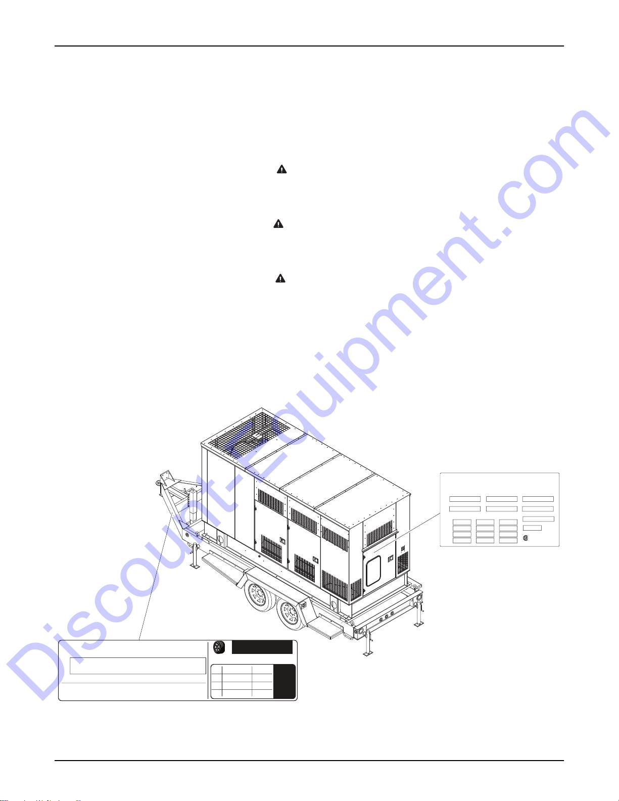
UNIT SERIAL NUMBER LOCATIONS
See Figure 2 to locate the unit ID tag and Vehicle Identification Number (VIN) tag on the unit. Important information,
such as the unit serial number, model number, VIN and tire loading information are found on these tags. Record the
information from these tags so it is available if the tags are lost or damaged. When ordering parts or requesting
assistance, you may be asked to provide this information.
UNIT ID Tag
Manufactured by Generac Mobile Products LLC,
a subsidiary of Generac Power Systems, Inc.
(920) 361-4442 (800) 926-9768
Country of Origin
Manufacturing Code
1 ph. 1.0PF 3 ph. .8PF 3 ph. 1.0PF
KW
KVA
V
A
Model
Weight (lbs/kg) RPM/Frequency
Located on control panel
(behind door)
Serial Number
Rating
FOR ELECTRICAL EQUIPMENT
Ins. Class
ONLY. POUR MATERIAL
ELECTRIQUE SEULEMENT.
209649
Form: SFC626B
VIN Tag
MANUFACTUREDBY/FABRIQUE PAR: Generac Mobile Products LLC DATE: 00/0000
GVWR/PNBV: 000KG (0000LBS) COLDINF. PRESS./
PRESS.DE
GAWR / PNBE TIRE / PNEU RIM / JANTE GONF A FROID - KPA(PSI/LPC) SGL / DUAL
EACH
AXLE
THIS VEHICLE CONFORMS TOALLAPPLICABLE STANDARDS PRESCRIBED UNDER THE U.S. FEDERAL MOTOR VEHICLE SAFETY STANDARDS(FMVSS)AND CANADIAN
MOTOR VEHICLE SAFETY REGULATIONS IN EFFECT ONTHE DATE OF MANUFACTURE.
CE VEHICULE EST CONFORMEATOUTES LES NORMES QUI LUI SONT APPLICABLES EN VERTU DU REGLEMENT SUR LA SECURITE DES VEHICULESAUTOMOBILES DU CANADA EN VIGUEUR A LA DATE SA
FABRICATION.
00000000000000000
V.I.N./N.I.V.:
XXX000
MODEL:
TYPE: TRAILER
TIRE AND LOADING INFORMATION
RENSEIGNEMENTS SUR LES
The weight of cargo should never exceed 0000KG (0000LBS)
Le poids du chargement ne doit jamais depasser 0000KG (0000LBS)
PNEUS ET LE CHARGEMENT
RENSEIGNEMENTS
SEE OWNER’S
MANUAL FOR
ADDITIONAL
INFORMATION
VOIR LE
MANUEL DE
L’USAGER
POUR
PLUS DE
02063
Figure 2 - Serial Number Locations
35319 C MGG155/210 Operating Manual 7
Page 14
General Information
Discount-Equipment.com
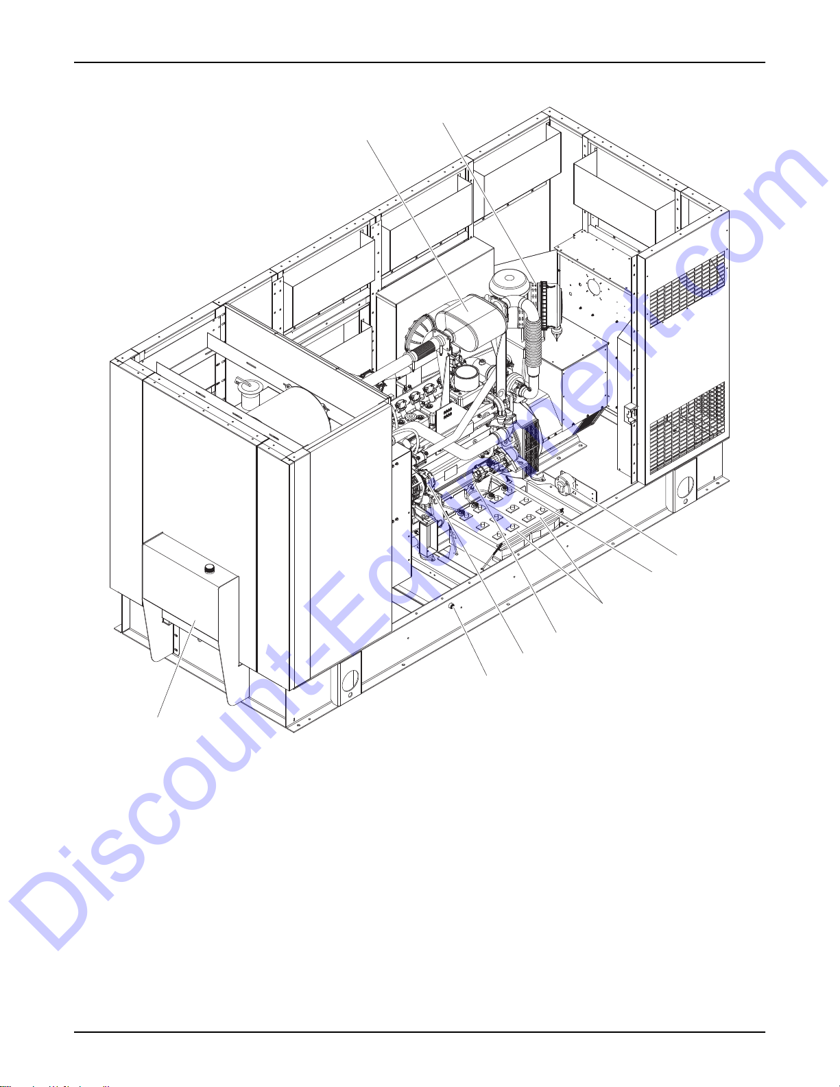
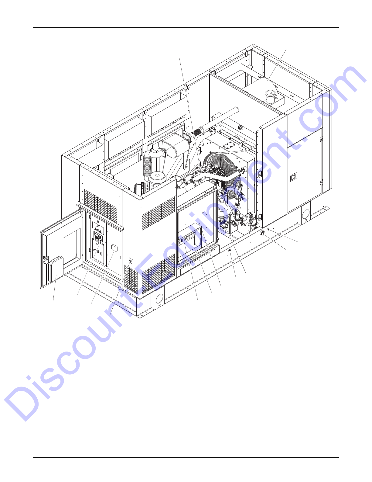
COMPONENT LOCATIONS
2
1
7
8
9
Figure 3 - MGG155 - Left Side
1. Catalyst exhaust muffler 6. Dipstick
2. Air filter 7. Alternator
3. Battery disconnect switch 8. Coolant drain
4. Starter 9. Oil reservoir
5.
12 volt batteries (2)
3
4
5
6
02032
8 MGG155/210 Operating Manual 35319 C
Page 15
General Information
Discount-Equipment.com
2
1
6
7
8
9
10
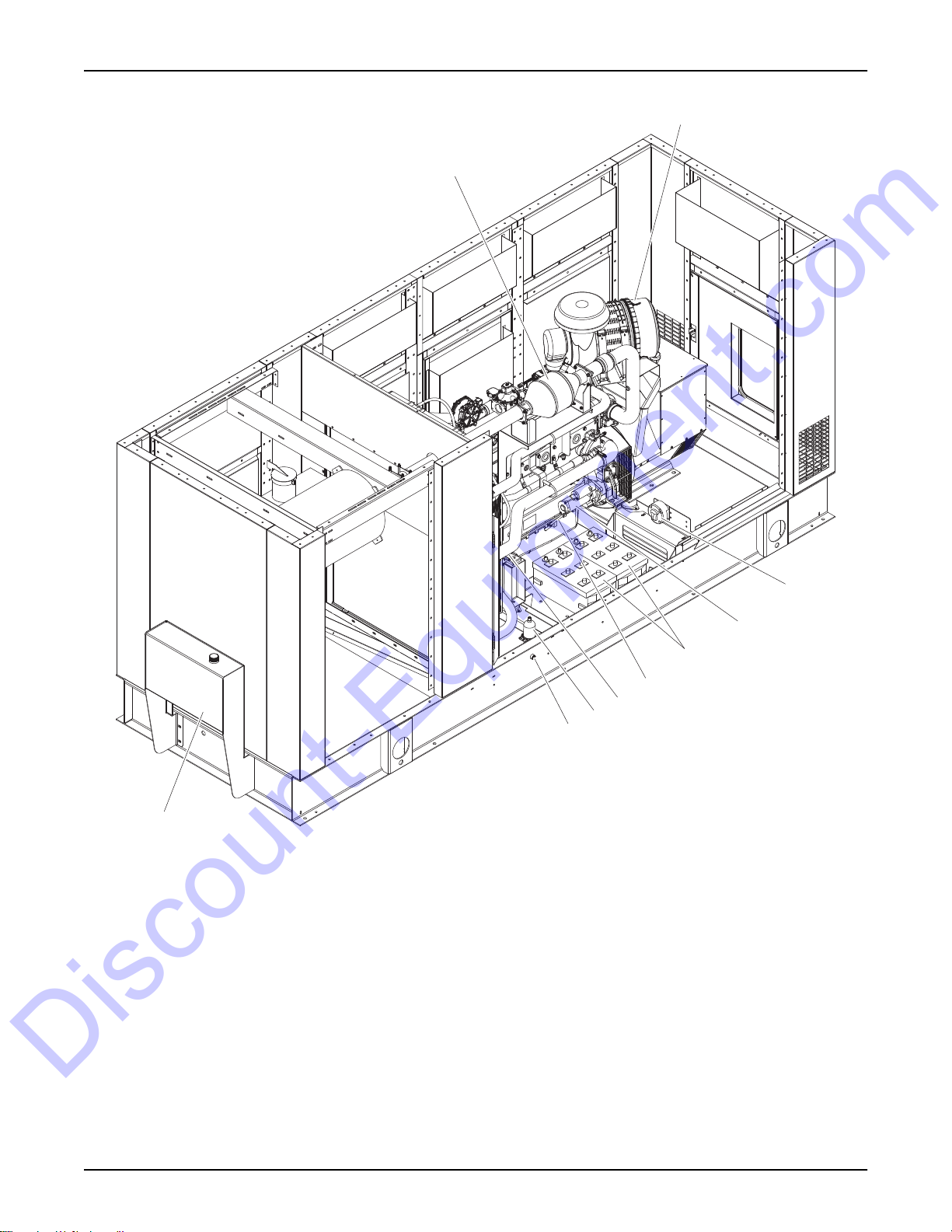
Figure 4 - MGG210 - Left Side
1. Catalyst exhaust muffler 6. Dipstick
2. Air filter 7. Alternator
3. Battery disconnect switch 8. Engine heater (optional)
4. Starter motor 9. Coolant drain
5. 12 volt batteries (2) 10. Oil reservoir
3
4
5
02033
35319 C MGG155/210 Operating Manual 9
Page 16
General Information
Discount-Equipment.com
2
1
5
6
7
13
12
11
10
Figure 5 - MGG155 and MGG210 - Right Side (MGG155 Shown)
1. Oil fill cap 8. Customer connection box
2. Silencer 9. Generator output connections
3. LP (liquid) inlet 10. Emergency stop switch
4. Natural gas (well gas) inlet 11. Main circuit breaker
5. Oil level controller 12. Control panel (see Figure 7)
6. Oil drain 13. Manual holder
7.
Customer convenience receptacles
8
9
3
4
02034
10 MGG155/210 Operating Manual 35319 C
Page 17
General Information
Discount-Equipment.com
3
1
2
654
7
8
16
15
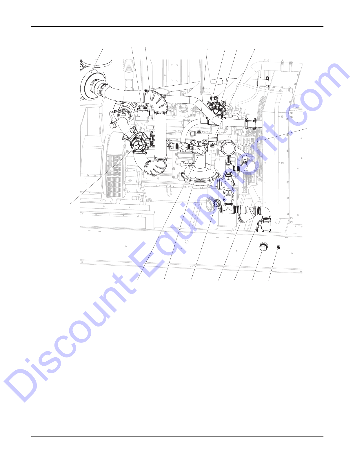
Figure 6 - Fuel System (MGG155 Shown)
1. Air filter 9. LP liquid inlet
2. Electronic throttle control 10. Natural gas (well gas) inlet
3. Integrated electronic pressure regulator 11. Manual ball valve (natural gas)
4. Natural gas lock-off 12. Strainer access
5. LP liquid lock-off 13. Pressure gauge (psi)
6. Vaporizer 14. Pressure regulator
7. Pressure switch 15. Access for regulator adjustment
8. Pressure gauge (inch WC) 16. Fuel/air mixer
14
13
12
11
10
9
00720
35319 C MGG155/210 Operating Manual 11
Page 18
General Information
EMERGENCY STOP
VOLTAGE
ADJUST
OFF
ON
PANEL
LIGHTS
Discount-Equipment.com
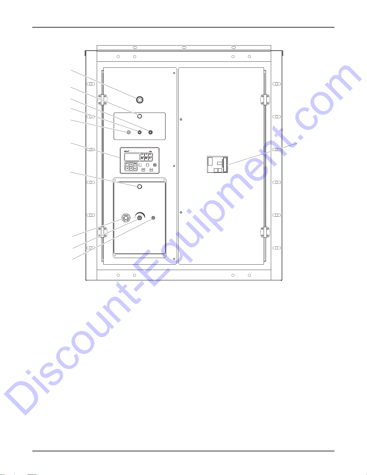
CONTROL PANEL
1
2
3
4
5
DC CIRCUIT
BREAKER
6
CONTROLLER
PANEL
LIGHT FUSE
FUSE
10
2
EMERGENCY STOP
VOLTAGE
ADJUST
ON
OFF
PANEL
LIGHTS
7
8
9
00578
Figure 7 - MGG155 and MGG210 Control Panel
1. Alarm horn 6. Digital controller
2. Panel light 7. Emergency stop switch (not on all units)
3. Panel light fuse (10A) 8. Voltage adjustment
4. Controller fuse (5A) 9. Panel lights switch
5. DC circuit breaker 10. Main circuit breaker
12 MGG155/210 Operating Manual 35319 C
Page 19
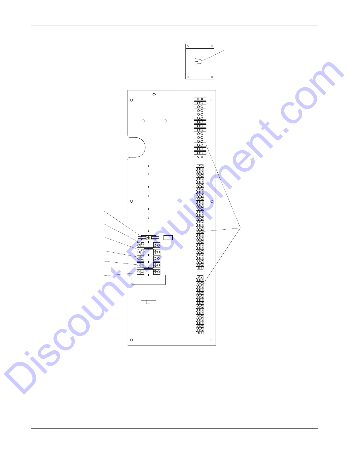
ELECTRICAL PANEL
Discount-Equipment.com
General Information
FUEL SELECT SWITCH
AUTO
NG
LP
TB1
1" X 2" WIREWAY
8
TB2
1
7
2
6
SR
5
4
3
FR
STR
CBCR
CBOR
iG-AVRi
iG-AVRi
TRANS/LV
5A FUSE
F3
TB3
02031
Figure 8 - Electrical Panel (Located Behind Control Panel Door)
1. Fuel select switch 5. Shunt trip relay
2. Terminal block (3) 6. Fuel relay
3. Circuit breaker open relay 7. Starter relay
4. Circuit breaker closed relay 8. Relay protection fuse (5A)
35319 C MGG155/210 Operating Manual 13
Page 20

General Information
Discount-Equipment.com
UNIT SET UP
This unit is designed to operate with natural gas or well gas as the primary fuel and LP liquid as the secondary fuel.
For units operating on well site gas, a well test must be performed prior to installation of the unit.
Well Site Approval
A well gas chromatography analysis must be performed prior to installation of the unit. A copy of the test report must
be sent to, and preapproved by, Generac Power Systems. If the unit is moved to a new location, a new well test
must be performed. For more information, contact Generac Mobile Products Technical Support.
The unit should be installed, serviced, tested, adjusted, and otherwise prepared for use by an Independent Authorized
Service Dealer. The owner is responsible for ensuring the unit emission control system meets all applicable state
and local regulations.
WARNING
Risk of Fire. Unit must be positioned in a manner that prevents combustible material
accumulation underneath. Failure to do so could result in death or serious injury.
(000147)
Fuel Connections
Almost all operation problems are related to the installation techniques used. DO NOT guess, be sure pipe size is
adequate for required flow rate. See Table 1, Table 2 and Table 3.
Natural Gas Connections
Follow the steps below:
1. Before connecting the natural gas fuel line to the unit, apply pipe sealant to the NPT threads of the fitting at
the end of the fuel line.
Note: Do not apply pipe sealant to the flared (flanged) end of the fitting.
2. Connect the fuel line to the two inch inlet, located on the right side of the unit’s frame.
3. Be certain that all connections are sealed and no leaks are present. The installer must verify that all gas
connections comply with all building codes.
4. Verify fuel supply pressure is adequate.
Purging the Natural Gas Fuel Line
After initial setup, it may be necessary to purge the natural gas fuel line before operating the unit. LP liquid must be
available as a secondary fuel to perform this procedure.
1. Open the control door located at the back of the unit.
2. Remove the three screws securing the left control panel door. A Fuel Select switch is located behind the
door. See Figure 8.
3. Move the Fuel Select switch to the LP or AUTO position.
14 MGG155/210 Operating Manual 35319 C
Page 21

General Information
Discount-Equipment.com
FUEL SELECT SWITCH
AUTO
NG
LP
00651
Figure 9 - Fuel Select Switch
4. Apply pipe sealant to the NPT threads of the pipe fitting at the end of the natural gas fuel line. Connect the
fuel line to the two inch inlet located on the right side of the unit’s frame.
Note: Do not apply pipe sealant to the flared (flanged) end of the fuel pipe.
5. Apply pipe sealant to the NPT threads of the pipe fitting at the end of the LP liquid fuel line. Connect the fuel
line to the 1/2 inch inlet located on the right side of the unit’s frame.
6. Be certain that all connections are sealed and no leaks are present. The installer must verify that all gas
connections comply with all building codes.
7. Verify fuel supply pressure is adequate.
Formula Example:
If a unit has a 160 hp engine 60 feet from the supply, the engine needs 10,000 BTU/hr per hp to run efficiently. For
natural gas fuel, there are 1015 BTU/ft3. From Table 1, a 60 foot run requires a minimum 1 inch pipe at full engine load.
160 hp x 10,000 BTU/Hr per hp = 1,600,000 BTU’s / per hour for proper operation
1,600,000
1, 015
Note: The incoming pressure must be approximately 20 psi to unit.
= 1576 cubic feet per hour
35319 C MGG155/210 Operating Manual 15
Page 22

General Information
Discount-Equipment.com
Table 1 - Natural Gas Flow Rate (ft3 / m3 Per Hour) per Pipe Length
Pipe
Length
1/2 in
(1 cm)
3/4 in
(2 cm)
1 in
(3 cm)
1−1/4 in
(3 cm)
1−1/2″
(4 cm)
Iron Pipe Size
2 in
(5 cm)
2−1/2 in
(6 cm)
3 in
(8 cm)
3–1/2 in
(9 cm)
4 in
(10 cm)
5 in
(13 cm)
6 in
(15 cm)
10 ft
(3 m)
20 ft
(6 m)
25 ft
(8 m)
30 ft
(9 m)
35 ft
(11 m)
40 ft
(12 m)
45 ft
(14 m)
50 ft
(15 m)
60 ft
(18 m)
70 ft
(21 m)
80 ft
(24 m)
90 ft
(27 m)
100 ft
(30 m)
125 ft
(38 m)
150 ft
(46 m)
200 ft
(61 m)
300 ft
(91 m
400 ft
(122 m)
500 ft
(152 m)
1,000 ft
(305 m)
1,500 ft
(457 m)
2,000 ft
(610 m)
2,723 ft
(830 m)
1,926 ft
(587 m)
1,722 ft
(525 m)
1,572 ft
(479 m)
1,456 ft
(444 m)
1,362 ft
(415 m)
1,284 ft
(391 m)
1,218 ft
(371 m)
1,112 ft
(339 m)
1,029 ft
(314 m)
963 ft
(294 m)
908 ft
(277 m)
861 ft
(262 m)
770 ft
(235 m)
703 ft
(214 m)
609 ft
(186 m)
497 ft
(151 m)
431 ft
(131 m)
385 ft
(117 m)
272 ft
(83 m)
222 ft
(68 m)
193 ft
(59 m)
5,765 ft
(1,757 m)
4,076 ft
(1,242 m)
3,646 ft
(1,111 m)
3,328 ft
(1,014 m)
3,082 ft
(939 m)
2,883 ft
(879 m)
2,718 ft
(828 m)
2,578 ft
(786 m)
2,354 ft
(717 m)
2,179 ft
(664 m)
2,038 ft
(621 m)
1,922 ft
(586 m)
1,823 ft
(556 m)
1,631 ft
(497 m)
1,489 ft
(454 m)
1,289 ft
(393 m)
1,053 ft
(321 m)
912 ft
(278 m)
815 ft
(248 m)
577 ft
(176 m)
471 ft
(144 m)
408 ft
(124 m)
10,975 ft
(3,345 m)
7,760 ft
(2,365 m)
6,941 ft
(2,116 m)
6,336 ft
(1,931 m)
5,866 ft
(1,788 m)
5,487 ft
(1,672 m)
5,174 ft
(1,577 m)
4,908 ft
(1,496 m)
4,480 ft
(1,366 m)
4,148 ft
(1,264 m)
3,880 ft
(1,183 m)
3,658 ft
(1,115 m)
3,471 ft
(1,058 m)
3,104 ft
(946 m)
2,834 ft
(864 m)
2,454 ft
(748 m)
2,004 ft
(611 m)
1,735 ft
(529 m)
152 ft
(46 m)
1097 ft
(334 m)
896 ft
(273 m)
776 ft
(237 m)
22,804 ft
(6,951 m)
16,125 ft
(4,915 m)
14,422 ft
(4,396 m)
13,166 ft
(4,013 m)
12,189 ft
(3,715 m)
11,402 ft
(3,475 m)
10,750 ft
(3,277 m)
10,198 ft
(3,108 m)
9,310 ft
(2,838 m)
8,619 ft
(2,627 m)
8,062 ft
(2,457 m)
7,601 ft
(2,317 m)
7,211 ft
(2,198 m)
6,450 ft
(1,966 m)
5,888 ft
(1,795 m)
5,099 ft
(1,554 m)
4,163 ft
(1,269 m)
3,606 ft
(1,099 m)
3,225 ft
(983 m)
2,280 ft
(695 m)
1,862 ft
(568 m)
1,612 ft
(491 m)
34,398 ft
(10,485 m)
24,323 ft
(7,414 m)
21,755 ft
(6,631 m)
19,860 ft
(6,053 m)
18,386 ft
(5,604 m)
17,199 ft
(5,242 m)
16,215 ft
(4,942 m)
15,383 ft
(4,689 m)
14,043 ft
(4,280 m)
13,001 ft
(3,963 m)
12,161 ft
(3,707 m)
11,466 ft
(3,495 m)
10,878 ft
(3,316 m)
9,729 ft
(2,965 m)
8,881 ft
(2,707 m)
7,692 ft
(2,345 m)
6,280 ft
(1,914 m)
5,439 ft
(1,658 m)
4,865 ft
(1,483 m)
3,440 ft
(1,049 m)
2,809 ft
(856 m)
2,432 ft
(741 m)
66,973 ft
(20,413 m)
47,357 ft
(14,434 m)
42,358 ft
(12,911 m)
38,667 ft
(11,786 m)
35,799 ft
(10,912 m)
33,487 ft
(10,207 m)
31,572 ft
(9,623 m)
29,951 ft
(9,129 m)
27,342 ft
(8,334 m)
25,314 ft
(7,716 m)
23,679 ft
(7,217 m)
22,324 ft
(6,804 m)
21,179 ft
(6,455 m)
18,943 ft
(5,774 m)
1,292 ft
(394 m)
14,976 ft
(4,565 m)
12,228 ft
(3,727 m)
10,589 ft
(3,228 m)
9,471 ft
(2,887 m)
6,697 ft
(2,041 m)
5,468 ft
(1,667 m)
4,736 ft
(1,444 m)
107,577 ft
(32,789 m)
76,068 ft
(23,186 m)
68,037 ft
(20,738 m)
62,109 ft
(18,931 m)
57,502 ft
(17,527 m)
53,788 ft
(16,395 m)
50,712 ft
(15,457 m)
48,110 ft
(14,664 m)
43,918 ft
(13,386 m)
40,660 ft
(12,393 m)
38,034 ft
(11,593 m)
35,859 ft
(10,930 m)
34,019 ft
(10,369 m)
30,427 ft
(9,274 m)
27,776 ft
(8,466 m)
24,055 ft
(7,332 m)
19,641 ft
(5,987 m)
17,009 ft
(5,184 m)
15,214 ft
(4,637 m)
10,758 ft
(3,279 m)
8,784 ft
(2,677 m)
7,607 ft
(2,319 m)
191,989 ft
(58,518 m)
135,757 ft
(41,379 m)
121,424 ft
(37,010 m)
110,845 ft
(33,786 m)
102,622 ft
(31,279 m)
95,994 ft
(29,259 m)
90,504 ft
(27,586 m)
85,860 ft
(26,170 m)
78,379 ft
(23,890 m)
72,565 ft
(22,118 m)
67,878 ft
(20,689 m)
63,996 ft
(19,506 m)
60,712 ft
(18,505 m)
54,303 ft
(16,552 m)
49,571 ft
(15,109 m)
42,930 ft
(13,085 m)
35,052 ft
(10,684 m)
30,356 ft
(9,253 m)
27,151 ft
(8,276 m)
19,199 ft
(5,852 m)
15,676 ft
(4,778 m)
13,576 ft
(4,138 m)
282,890 ft
(86,225 m)
200,034 ft
(60,970 m)
178,915 ft
(54,533 m)
163,327 ft
(49,782 m)
151,211 ft
(46,089 m)
141,445 ft
(43,112 m)
133,356 ft
(40,647 m)
126,512 ft
(38,561 m)
115,489 ft
(35,201 m)
106,922 ft
(32,590 m)
100,017 ft
(30,485 m)
94,297 ft
(28,742 m)
89,458 ft
(27,267 m)
80,013 ft
(24,388 m)
73,042 ft
(22,263 m)
63,256 ft
(19,280 m)
51,648 ft
(15,742 m)
44,729 ft
(13,633 m)
40,007 ft
(12,194 m)
28,289 ft
(8,622 m)
23,098 ft
(7,040 m)
20,003 ft
(6,097 m)
396,270 ft
(120,783 m)
280,205 ft
(85,406 m)
250,623 ft
(76,390 m)
228,787 ft
(69,734 m)
211,815 ft
(64,561 m)
198,135 ft
(60,392 m)
186,804 ft
(56,938 m)
177,217 ft
(54,016 m)
161,777 ft
(49,310 m)
149,776 ft
(46,652 m)
140,103 ft
(42,703 m)
132,090 ft
(40,261 m)
125,312 ft
(38,195 m)
112,082 ft
(34,163 m)
102,317 ft
(31,186 m)
88,609 ft
(27,008 m)
72,349 ft
(22,052 m)
62,656 ft
(19,098 m)
56,041 ft
(17,081 m)
39,627 ft
(12,078 m)
32,355 ft
(9,862 m)
28,021 ft
(8541 m)
724,020 ft
(220,681 m)
511,959 ft
(156,045 m)
457,910 ft
(139,571 m)
418,013 ft
(127,410 m)
387,005 ft
(117,959 m)
362,010 ft
(110,341 m)
341,306 ft
(104,030 m)
323,791 ft
(98,692 m)
295,580 ft
(90,093 m)
273,654 ft
(83,410 m)
255,980 ft
(78,023 m)
241,340 ft
(73,560 m)
228,955 ft
(69,785 m)
204,784 ft
(62,418 m)
186,941 ft
(56,980 m)
161,896 ft
(49,346 m)
132,187 ft
(40,291 m)
114,478 ft
(34,893 m)
102,392 ft
(31,209 m)
72,402 ft
(22,068 m)
59,116 ft
(18,019 m)
51,196 ft
(15,605 m)
1,181,799 ft
(360,212 m)
838,658 ft
(255,623 m)
747,435 ft
(227,818 m)
682,312 ft
(207,969 m)
631,698 ft
(192,542 m)
590,900 ft
(180,106 m)
557,105 ft
(169,806 m)
528,517 ft
(161,092 m)
482,467 ft
(147,056 m)
446,678 ft
(136,148 m)
417,829 ft
(127,354 m)
393,933 ft
(120,071 m)
373,718 ft
(113,909 m)
334,263 ft
(101,883 m)
305,139 ft
(93,006 m)
264,258 ft
(80,546 m)
215,766 ft
(65,765 m)
186,859 ft
(56,955 m)
167,132 ft
(50,942 m)
118,180 ft
(36,021 m)
96,493 ft
(29,411 m)
83,566 ft
(25,471 m)
16 MGG155/210 Operating Manual 35319 C
Page 23

General Information
Discount-Equipment.com
LP Liquid Connections (Liquid Withdrawal System)
Use the following chart to determine the supply pipe size for LP liquid.
Formula Example:
If a unit has a 135 hp engine 80 feet from the supply, the engine needs 449 ft3/hr of LP vapor to run efficiently. For
liquid propane vapor fuel, there is 2500 BUT/ft3. From Table 2, an 80 foot run requires a minimum 1/4 inch pipe at
full engine load.
3
2500 ft
*Cubic feet of vapor at 60°F (16°C) per gallon of liquid at 60°F (16°C).
/hr x 449 ft3/hr = 1,122,500 BTU/ft
3
449 ft
/hr
36.39*
= 12.33 gallons per hour
3
35319 C MGG155/210 Operating Manual 17
Page 24

General Information
Discount-Equipment.com
Liquid
Propane
Flow
10 gal/hr
(38 L/hr)
15 gal/hr
(57 L/hr)
20 gal/hr
(76 L/hr)
40 gal/hr
(151 L/hr)
60 gal/hr
(227 L/hr)
80 gal/hr
(303 L/hr)
100 gal/hr
(379 L/hr)
120 gal/hr
(454 L/hr)
140 gal/hr
(530 L/hr)
160 gal/hr
(606 L/hr)
180 gal/hr
(681 L/hr)
200 gal/hr
(757 L/hr)
240 gal/hr
(908 L/hr)
280 gal/hr
(1,060 L/hr)
300 gal/hr
(1,136 L/hr)
350 gal/hr
(1,325 L/hr)
400 gal/hr
(1,514 L/hr)
1/4 in
(0.6 cm)
Schedule Schedule Schedule Schedule Schedule Schedule Schedule
40 80 40 80 40 80 40 80 40 80 40 80 40 80
729 ft
(222 m)
324 ft
(99 m)
182 ft
(55 m)
46 ft
(14 m)
20 ft
(6 m)
11 ft
(3 m)
(2 m)
416 ft
(127 m)
185 ft
(56 m)
104 ft
(32 m)
(8 m)
(3 m)
(2 m)
7 ft
(1 m)
- - 23 ft
- - 15 ft
- - 13 ft
- - - - 37 ft
- - - - 30 ft
- - - - 21 ft
- - - - 15 ft
- - - - 13 ft
------38 ft
------30 ft
26 ft
11 ft
6 ft
4 ft
Table 2 - LP Liquid Line Sizing Chart
Iron Pipe Size
3/8 in
(1 cm)
----------- -
----------- -
825 ft
(251 m)
205 ft
(62 m)
92 ft
(28 m)
51 ft
(16 m)
33 ft
(10 m)
(7 m)
(5 m)
(4 m)
521 ft
(159 m)
129 ft
(39 m)
58 ft
(18 m)
32 ft
(10 m)
21 ft
(6 m)
15 ft
(5 m)
9 ft
(3 m)
8 ft
(2 m)
1/2 in
(1 cm)
3/4 in
(2 cm)
1 in
(3 cm)
1-1/4 in
(3 cm)
1-1/2 in
(4 cm)
Distance
----------
745 ft
(227 m)
331 ft
(101 m)
187 ft
(57 m)
119 ft
(36 m)
83 ft
(25 m)
61 ft
(19 m)
47 ft
(14 m)
(11 m)
(9 m)
(6 m)
(5 m)
(4 m)
504 ft
(154 m)
224 ft
(68 m)
127 ft
(39 m)
81 ft
(25 m)
56 ft
(17 m)
41 ft
(12 m)
32 ft
(10 m)
25 ft
(8 m)
20 ft
(6 m)
14 ft
(4 m)
10 ft
(3 m)
9 ft
(3 m)
------- -
------- -
735 ft
(224 m)
470 ft
(143 m)
326 ft
(99 m)
240 ft
(73 m)
184 ft
(56 m)
145 ft
(44 m)
118 ft
(36 m)
81 ft
(25 m)
60 ft
(18 m)
52 ft
(16 m)
(12 m)
(9 m)
537 ft
(164 m)
343 ft
(105 m)
238 ft
(73 m)
175 ft
(53 m)
134 ft
(41 m)
106 ft
(32 m)
86 ft
(26 m)
59 ft
(18 m)
44 ft
(13 m)
38 ft
(12 m)
28 ft
(9 m)
22 ft
(7 m)
----- -
----- -
----- -
813 ft
(248 m)
623 ft
(190 m)
491 ft
(150 m)
399 ft
(122 m)
277 ft
(84 m)
204 ft
(62 m)
177 ft
(54 m)
130 ft
(40 m)
99 ft
(30 m)
618 ft
(188 m)
473 ft
(144 m)
373 ft
(114 m)
303 ft
(92 m)
211 ft
(64 m)
155 ft
(47 m)
135 ft
(41 m)
99 ft
(30 m)
75 ft
(23 m)
--- -
--- -
--- -
--- -
--- -
--- -
785 ft
(239 m)
578 ft
(176 m)
433 ft
(132 m)
623 ft
(190 m)
459 ft
(140 m)
344 ft
(105 m)
--
--
980 ft
(299 m)
794 ft
(242 m)
How to use chart:
1. Having determined the required flow at point of use, locate this flow in the left hand column. If this falls between
two figures, use the larger of the two.
2. Determine total length of piping required from source to point of use.
18 MGG155/210 Operating Manual 35319 C
Page 25

General Information
Discount-Equipment.com
3. Read across chart from left (required flow) to right to find the total length which is equal to, or exceeds, the
distance from source to use.
4. From this point, read up to find the correct size of pipe required.
Valve and Fitting Pipe Equivalents
Table 3 - Valve & Fitting Pipe Equivalents
Equivalent Length Of Steel Pipe
Nominal Pipe Size (NPT)
Fitting
45° Screwed
Elbow
90° Screwed
Elbow
Screwed T
Thru Run
Screwed T
Thru Branch
Screwed
Globe Valve*
Screwed
Angel Valve*
Flanged
Globe Valve*
Flanged
Angle Valve*
3/4 in
(2 cm)
1 in
(3 cm)
1-1/4 in
(3 cm)
1-1/2 in
(4 cm)
2 in
(5 cm)
2-1/2 in
(6 cm)
3 in
(8 cm)
Schedule Schedule Schedule Schedule Schedule Schedule Schedule
40 80 40 80 40 80 40 80 40 80 40 80 40 80
1.2 ft
(0.4 m)
1.8 ft
(0.5 m)
1.4 ft
(0.4 m)
4.6 ft
(1.4 m)
14.0 ft
(4.3 m)
11.0 ft
(3.4 m)
0.9 ft
(0.3 m)
1.6 ft
(0.5 m)
1.3 ft
(0.4 m)
4.0 ft
(1.2 m)
10.0 ft
(3.0 m)
8.0 ft
(2.4 m)
- - - - - - 30.0 ft
- - - - - - 12.0 ft
1.3 ft
(0.4 m)
2.3 ft
(0.7 m)
1.7 ft
(0.5 m)
5.6 ft
(1.7 m)
21.0 ft
(6.4 m)
13.0 ft
(4.0 m)
1.2 ft
(0.4 m)
2.1 ft
(0.6 m)
1.6 ft
(0.5 m)
5.3 ft
(1.6 m)
16.0 ft
(4.9 m)
10.0 ft
(3.0 m)
1.7 ft
(0.5 m)
3.1 ft
(0.9)
2.4 ft
(0.7 m)
7.9 ft
(2.4 m)
24.0 ft
(7.3 m)
10.5 ft
(3.2 m)
1.5 ft
(0.5 m)
2.9 ft
(0.9)
2.3 ft
(0.7 m)
7.3 ft
(2.2 m)
19.0 ft
(5.8 m)
8.5 ft
(2.6 m)
2.0 ft
(0.6 m)
3.7 ft
(1.1 m)
2.8 ft
(0.9 m)
9.3 ft
(2.8 m)
39.0 ft
(11.9 m)
20.0 ft
(6.1 m)
(9.1 m)
(3.7 m)
1.8 ft
(0.5 m)
3.4 ft
(1.0 m)
2.6 ft
(0.8 m)
8.6 ft
(2.6 m)
27.0 ft
(8.2 m)
16.0 ft
(4.9 m)
24.0 ft
(7.3 m)
10.0 ft
(3.0 m)
2.6 ft
(0.8 m)
4.6 ft
(1.4 m)
3.6 ft
(1.1 m)
12.0 ft
(3.7 m)
42.0 ft
(12.8 m)
32.0 ft
(9.8 m)
4.10 ft
(1.2 m)
14.5 ft
(4.4 m)
2.4 ft
(0.7 m)
4.4 ft
(1.3 m)
3.3 ft
(1.0 m)
11.0 ft
(3.4 m)
34.5 ft
(10.5 m)
26.5 ft
(8.1 m)
34.0 ft
(10.4 m)
12.0 ft
(3.7 m)
3.0 ft
(0.9 m)
5.3 ft
(1.6 m)
4.2 ft
(1.3 m)
15.0 ft
(4.6 m)
24.0 ft
(7.3 m)
7.5 ft
(2.3 m)
2.8 ft
(0.9 m)
5.1 ft
(1.6 m)
4.0 ft
(1.2 m)
14.0 ft
(4.3 m)
20.0 ft
(6.1 m)
6.0 ft
(1.8 m)
- - 46.0 ft
- - 19.0 ft
3.8 ft
(1.2 m)
6.9 ft
(2.1 m)
5.4 ft
(1.6 m)
17.0 ft
(5.2 m)
46.0 ft
(14.0 m)
19.0 ft
(5.8 m)
(14.0)
(5.8 m)
3.7 ft
(1.1 m)
6.5 ft
(2.0)
5.0 ft
(1.5 m)
16.0 ft
(4.9 m)
39.0 ft
(11.9 m)
16.0 ft
(4.9 m)
39.0 ft
(11.9 m)
16.0 ft
(4.9 m)
* Reg O A7500 series valves.
Electrical Connections
Class 1 wiring methods must be used for field wiring connections to terminals of a class 2 circuit. It is the responsibility
of the owner/operator to arrange for these procedures to be performed by a licensed electrical contractor and ensure
conformance to all applicable codes, including local codes specific to your municipality/city/county and state. Wire
size and insulation type should be as required by National Electrical Code (NEC), state and local regulations.
DANGER
ELECTROCUTION. NEVER CONNECT THIS UNIT TO THE ELECTRICAL SYSTEM OF
ANY BUILDING UNLESS A LICENSED ELECTRICIAN HAS INSTALLED AN APPROVED
TRANSFER SWITCH. FAILURE TO DO SO WILL RESULT IN DEATH OR SERIOUS
INJURY. (000150)
35319 C MGG155/210 Operating Manual 19
Page 26

General Information
Discount-Equipment.com
WARNING
Only qualified service personnel may install, operate and maintain this equipment.
Failure to follow proper installation requirements could result in death, serious injury,
and damage to equipment or property. (000182)
DANGER
ELECTROCUTION. VERIFY ELECTRICAL SYSTEM IS PROPERLY GROUNDED
BEFORE APPLYING POWER. FAILURE TO DO SO WILL RESULT IN DEATH OR
SERIOUS INJURY. (000152)
DUAL FUEL SYSTEM
This unit is equipped with a dual fuel system. This type of fuel system allows the unit to run on either natural gas
(primary) or LP liquid (secondary). In the event that the primary source becomes unavailable, the unit will automatically
switch to the secondary source. It can do so while in operation.
Natural Gas (Well Gas) Fuel System
Natural gas is supplied from a utility supply line or well site in its vapor state through in-ground piping. The vapor
enters the large fuel inlet located on the right side of the unit frame.
LP Liquid Withdrawal Fuel System
LP is supplied as a liquid in pressurized tanks. The liquid must be converted to its gaseous state before it is introduced
into the engine carburetor. The unit is equipped with a vaporizer converter to accomplish this. The LP liquid enters
the fuel system through the small fuel inlet located on the right side of the frame. As the liquid passes through the
vaporizer, heated engine coolant is passed through the vaporizer to provide the necessary heat for conversion of
the fuel from a liquid to a gaseous state.
DANGER
EXPLOSION AND FIRE. FUEL AND VAPORS ARE EXTREMELY FLAMMABLE AND
EXPLOSIVE. ADD FUEL IN A WELL VENTILATED AREA. KEEP FIRE AND SPARK
AWAY. FAILURE TO DO SO WILL RESULT IN DEATH OR SERIOUS INJURY. (000105)
IMPORTANT: THIS UNIT IS NOT DESIGNED TO OPERATE ON LP VAPOR. If your LP supply tank does
not have a liquid withdrawal system, a licensed LP supply company will need to install the correct fitting to
allow for it. For special fuel system configurations, contact Generac Mobile Products Technical Support.
DC FUSES
Located inside the control panel, the fuses protect the control panel wiring and components from damaging overload.
For fuse location and identification, see Figure 7.
GENERATOR AND LOAD COMPATIBILITY
This unit is a revolving field, alternating current type generator set. The generator is designed to supply electrical
power for the operation of compatible electrical loads.
The generator must be fully compatible with the rated voltage, phase rotation, and frequency of the connected
electrical loads. The generator, connected electrical devices, or both, can be damaged if voltage, phase, and frequency
are not compatible.
See the data label affixed to the unit for rated AC voltage, wattage, amperage, number of phases, etc.
20 MGG155/210 Operating Manual 35319 C
Page 27

General Information
Discount-Equipment.com
ENGINE/GENERATOR PROTECTIVE DEVICES
The unit may be required to operate for long periods of time without an operator on hand to monitor operating
conditions. For this reason, the unit has numerous sensors to provide the control panel with the information it needs
to protect both the engine and generator. The control panel is designed to shut down the engine if potentially damaging
conditions occur. These conditions can include low oil pressure, high coolant temperature, low coolant level, engine
overspeed, over or under voltage, over or under frequency, etc. These settings are configured at the factory and can
be changed/adjusted by an Independent Authorized Service Dealer if required.
DIGITAL CONTROLLER
The generator leaves the factory with the controller warning set at 105% load and shutdown set at 110% load. The
unit is equipped with a digital controller with paralleling capabilities. The paralleling feature allows the operator to
synchronize multiple controllers and distribute the load between units. Contact Generac Mobile Products Technical
Support for more information about this feature.
21
20
19
2
1
1718
16
Figure 10 - Digital Controller Pushbuttons and LEDs
3
4
1112131415
5
6
7
8
9
10
01754
1. Horn Reset: Deactivates the horn (audible alarm).
2. Mode ←: Cycles backward through genset operation modes.
3. Mode →: Cycles forward through genset operation modes.
4. Fault Reset: Acknowledges faults and alarms.
5. Start: Starts the genset in manual (MAN) mode.
6. Stop: Stops the genset in manual (MAN) mode.
7. Bus: Green LED is on if bus voltage is present and within limits.
8. GCB ON: Green LED is on if generator circuit breaker feedback is active. Flashes during synchronizing.
9. Genset Failure: Red LED starts flashing when any failure occurs. After Fault Reset button is pressed,
changes to steady light (if an alarm is still active) or is off (if no alarm is active).
35319 C MGG155/210 Operating Manual 21
Page 28

General Information
Discount-Equipment.com
10. Gen Voltage Present: Green LED is on if generator voltage is present and within limits.
11. GCB ON (I)/OFF (O): Opens and closes (synchronizes) the generator circuit breaker in manual MAN mode.
12. MCB ON: Green LED is on if the mains circuit breaker feedback is active. Flashes during reverse synchro-
nizing (synchronizing of the loaded genset back to the restored mains).
13. MCB ON (I)/OFF (O): Opens and closes (synchronizes) the mains circuit breaker in manual MAN mode.
14. Mains Voltage Present: Green LED is on if voltage on the mains terminals is present (in SPI and SPtM).
LED is not active in MINT, COX.
15. Mains Failure: Red LED starts flashing when the mains failure occurs and genset does not run, changes to
steady light when the genset starts, and then turns off when the mains restores.
16. →: Moves history record displayed columns to the right, five percent increase of edited setpoint’s value
(step given by the setpoint range), go back from Alarm list.
17. ↓: Select the setpoint, select the screen, select history record or decrease setpoint value.
18. ←: Moves history record displayed columns to the left, five percent decrease of edited setpoint’s value (step
given by the setpoint range), view Alarm list from measurement screens.
19. ↑: Select the setpoint, select the screen, select history record or increase setpoint value.
20. Esc:
21. Enter:
Where Function
Measurement screens,
Alarm list
Setpoints screen Go to Menu screen; within setpoint group, go to group list
Setpoint edit Leave setpoint edit without changes
History screen Go to Menu screen
FastEdit screen FastEdit exit (to previous measurement screen) without changes
Language screen Language screen exit (to Menu) without save
Where Function
Menu screen Go to selected display group (Measurement CU, Measurement IO.)
Measurement screens,
Alarm list
Setpoints screen Go to selected setpoint group
Setpoint edit Start setpoint edit/save changes
History screen Go to the first column of the first history record
FastEdit screen FastEdit exit (to previous measurement screen) with setpoint change
Language screen Language screen exit (to Menu) and save selection
Go to MENU screen
Go to FastEdit screen, hold Enter button for four seconds, then it is
possible to adjust selected setpoint. (Typically Base load for standard
SPtM.)
For more detailed controller information, see the controller operator guide included with the unit.
Setting the Clock
To set the clock on the digital controller, press Esc, then select Setpoints>Date/Time>Time. Press Enter. Use the up
and down arrows to adjust the settings, then press Enter.
22 MGG155/210 Operating Manual 35319 C
Page 29

Section 3 - Operation
Discount-Equipment.com
The operation of this unit should only be performed by an authorized operator; that is, someone who has been
properly trained by an Independent Authorized Service Dealer. Contact your local Independent Authorized Service
Dealer for assistance in training authorized operators. Read the operating manual thoroughly and understand all
instructions before operating the equipment.
The following instructions assume that the unit has been properly set up, serviced, tested, adjusted, and otherwise
prepared for use by an Independent Authorized Service Dealer. Read the safety information carefully before
attempting to operate this equipment.
PRESTART CHECKLIST
When the initial installation is complete, these checks must be performed before starting the engine. These checks
are not required before each start, only after the initial installation.
CAUTION
Do not apply high voltage to windings in moisture-saturated conditions. Serious damage to
genset and property can result. (000153)
Note: These precautions are extremely critical in locations such as seaboard installations and other high humidity
areas. Some installations will be in environments that are much more corrosive than others.
Verify battery disconnect switch is turned ON.
Verify unit is positioned in a stable manner.
Verify proper clearance on all sides and top of enclosure.
Verify unit is a safe distance from any flammable or combustible material.
Verify no load is connected to unit.
Inspect the engine and genset and verify there are no loose wires or components. Tighten if
necessary.
Verify engine oil level is correct. See Check Engine Fluids.
Verify engine coolant level is correct. See Adding Coolant.
Verify the controller is in STOP mode by pressing the STOP button.
Verify the fuel valve is open and the pressure and flow rate are correct.
Remove all tools, rags, etc. from inside the unit enclosure. Close and secure all enclosure doors prior
to starting the unit.
MANUALLY STARTING THE UNIT
This unit is designed to operate on Natural Gas (NG)/well gas or LP liquid. At oil well sites, LP liquid is typically used
to start the unit until the pump jack brings the well gas (natural gas) up to the surface. The unit fuel system will detect
when there is sufficient pressure to switch to natural gas as the primary fuel source.
Natural Gas (Well Gas) Start Up
If there is sufficient pressure in the well gas fuel line (10-20 psi [69-138 kPa]), the unit can be started directly on well
gas. Follow the steps below:
1. Open the manual ball fuel valve located just inside the frame. See Fuel System (MGG155 Shown).
2. Check for fuel leaks.
3. Press the START on the digital controller. The controller will sense the type of fuel entering the system and
will display “ALI NG Fuel Select”.
Note: If the unit will not start, verify the Fuel Select switch is set to NG or AUTO. See Figure 9.
35319 C MGG155/210 Operating Manual 23
Page 30

Operation
Discount-Equipment.com
LP Liquid Start Up
4. Open the LP liquid tank supply valve and the natural gas manual fuel valve (see Figure 6 for location). If
any leaks are detected, correct them immediately.
5. Press the START button on the digital controller.
6. When the natural gas pressure reaches 10-20 psi (69-138 kPa), move the Fuel Select switch to the NG
position. (You may have to toggle the switch between NG and LP until the unit runs smoothly on NG.)
7. Move the switch to AUTO.
Note: It will not be necessary to purge the fuel lines after shutting the unit down for maintenance or service unless
the fuel lines have been disconnected.
When the unit reaches operation speed, verify the voltage setting is correct and adjust if necessary. If the engine
fails to start, see Troubleshooting.
AUTO (REMOTE) STARTING THE UNIT
Connect the remote start contact to the remote start terminals on the terminal block (#12 and #34). Follow all NEC,
state and local regulations.
Note: The bonding plate may need to be removed. See Figure 12 for bonding plate location.
A ground connection is located next to the lugs. The generator neutral is bonded to ground when it is shipped from
the factory. The bonding plate may need to be removed if the generator is used as a standby power source.
INSTALLATION SHOULD BE IN COMPLIANCE WITH THE NATIONAL ELECTRICAL CODE (NEC), STATE AND
LOCAL REGULATIONS.
02022
Figure 11 - Terminal Block
PARALLEL SETUP AND OPERATION
The unit can be operated in parallel with other parallel-capable units. To ensure the units to be used in parallel are
appropriate for the load, contact Generac Mobile Products Technical Support at 1-800-926-9768.
Before running units in parallel, make sure each unit is operating properly. Set up auto (remote) starting on each unit.
Paralleling Two Units
Using the provided CAN parallel cable, connect one end of the cable to the terminal block of the first unit and the
other end to the terminal block of the second unit. Match each wire with the corresponding color wire connected to
the terminal block; yellow to yellow, green to green, black (shield) to black. Connect the provided 120 ohm resistor
24 MGG155/210 Operating Manual 35319 C
Page 31

Operation
Discount-Equipment.com
to the unused terminals on both units as shown on the decal located below the terminal blocks.
Paralleling More Than Two Units
To parallel more than two units, connect another CAN parallel cable from the unused terminal on the second unit
(remove resistor, if necessary) to a terminal on the next unit. Continue chaining the parallel units. Connect the resistors
to the unused terminals on the first and last units in the series.
Once the units are set up in parallel, they will share the load evenly during normal operation. If parallel units are in
auto mode and one unit is shut down, the load will transfer to the remaining units on line. If all paralleled units are
in manual mode, press the GCB (Generator Circuit Breaker) button on the controller, and the load gradually transitions
to the other units.
Note: When one or more units shut down, any remaining units will shut down if the increase in proportional load is
greater than what the unit is rated for. Contact Generac Mobile Products Technical Support to verify the units to be
used in parallel are appropriate for the planned load.
OPERATION CHECKS
With the engine running, verify the following:
Verify there are no fuel leaks. If a fuel leak is detected, stop the engine immediately by pressing STOP
on the controller. Repair any fuel leaks before proceeding.
Verify there are no coolant or oil leaks. If a leak is detected, stop the engine immediately and repair the
leak before proceeding.
Verify that operation is smooth. If belt squeals, vibrations or other sources of noise exist, stop the
engine immediately and repair before proceeding.
Verify correct voltage (line−to−line and line−to−neutral) at the genset.
Verify phase rotation is the same as the attached equipment.
Minor adjustment of the output voltage is made using the voltage adjust potentiometer on the control
panel.
WARNING
DO NOT open coolant system until engine has completely cooled. Doing so could
result in serious injury. (000154)
After the operational checks are made, stop the engine by pressing STOP on the controller, and wait
for the engine to cool. When the engine is cool, check engine oil and coolant levels.
OVERCRANK SHUTDOWN
After a pre-specified duration of cranking, this function ends cranking if the engine has failed to start. The default
settings are:
• The unit will attempt to start (crank) three times.
• Each crank cycle lasts 10-15 seconds, followed by a five second rest (to cool the starter).
• After three starting attempts, the controller alarm will sound and the LCD window on the controller will display
“Start Fail Alarm”.
35319 C MGG155/210 Operating Manual 25
Page 32

Operation
Discount-Equipment.com
ENGINE OIL REPLENISHMENT SYSTEM
This unit is equipped with an engine oil replenishment system. The system eliminates the need for frequent filling
and checking of the crankcase. The system consists of a oil reservoir tank and an oil level regulator. The regulator
is mounted so the centerline of the sight glass is at the same height as the level of the oil in the crankcase. When
the engine oil level is low, the float will trigger the reservoir tank to send fresh oil to the crankcase. The regulator
delivers only that amount of oil required to maintain a constant oil level in the crankcase. A fine mesh screen in the
regulator provides protection against damage by contaminants and abrasive foreign matter.
The regulator is pre-set to the correct level at the factory and should not require adjustment. See Check Engine
Fluids for more information.
DERATING FOR ALTITUDE
All units are subject to derating for altitude and temperature; this will reduce the available power for operating tools
and accessories connected to the receptacles. Typical reductions in performance are a derate of -3% for every 1000
ft (305 m) above 1200 ft (366 m) above sea level and a derate of -1% per 10°F (-12ºC) increase in ambient air
temperature over 77°F (25°C).
GENERATOR OUTPUT CONNECTIONS
The unit is equipped with lug connections, located inside the customer connection box. The connection box is located
behind the door on the right side of the unit. See Figure 5. The lugs provide connection points for attachment of
external loads to the generator.
DANGER
RISK OF ELECTROCUTION. BEFORE ANY CONNECTIONS ARE MADE TO THE
GENERATOR, VERIFY THE MAIN CIRCUIT BREAKER AND THE BATTERY DISCON-
NECT SWITCH ARE OFF (O). POTENTIALLY LETHAL VOLTAGES MAY BE PRESENT
AT THE GENERATOR CONNECTION LUGS.
WARNING
Only a trained and licensed electrician should perform wiring and connections to
unit. Failure to follow proper installation requirements could result in death, serious
injury, and damage to equipment or property. (000155)
Connections to the lugs should be made by running the power cables up through the opening in the bottom of the
box. DO NOT make any connections directly to the lugs without routing the cables through the slot. Use a hex-wrench
to tighten the cable connections.
The connection box door is equipped with a safety interlock switch that will trip the main circuit breaker and disable
the voltage regulator if the door is opened while the unit is operating.
DANGER
ELECTROCUTION. DO NOT DISABLE OR MODIFY THE CONNECTION BOX DOOR
SAFETY SWITCH. DOING SO WILL RESULT IN DEATH OR SERIOUS INJURY. (000157)
A ground connection is located next to the lugs. The generator neutral is bonded to ground when it is shipped from
the factory. The bonding plate may need to be removed if the generator is used as a standby power source.
INSTALLATION SHOULD BE IN COMPLIANCE WITH THE NATIONAL ELECTRICAL CODE (NEC), STATE AND
LOCAL REGULATIONS.
26 MGG155/210 Operating Manual 35319 C
Page 33

Operation
Discount-Equipment.com
1
Figure 12 - Generator Output Connections
1. Connections lugs 2. Bonding plate
CUSTOMER CONVENIENCE RECEPTACLES
The unit is equipped with two 120V GFCI receptacles, located to the right of the customer connection box. These
receptacles are not routed through the main circuit breaker. Each receptacle has its own circuit breaker, located
directly above it.
20A Circuit Breakers
2
00862
GFCI Receptacles
Figure 13 - 120V GFCI Receptacles
Power to the receptacles is available any time the generator is running, even if the main
circuit breaker is OFF (O). VERIFY ANY EQUIPMENT CONNECTED TO THE CONVE-
NIENCE RECEPTACLES IS TURNED OFF BEFORE TURNING THE BREAKERS ON and
the output voltage is correct for the equipment that is connected to the receptacles. Improper
voltage may cause equipment damage, property damage, or malfunction.
35319 C MGG155/210 Operating Manual 27
02021
Page 34

Operation
Discount-Equipment.com
MAIN CIRCUIT BREAKER
When the main circuit breaker is OFF (O), power is interrupted between the bus connections and the generator.
Once connections have been made to the bus bars and the generator has been started and allowed to reach normal
operating temperature, the breaker may be switched ON (I).
The main circuit breaker will be tripped, disconnecting power to the bus connections, if any of the following conditions
occur while the unit is running:
• Overload of the generator circuits to the bus connections. At 105% load, there will be an audible warning.
At 110% load, the breaker opens and power will be disconnected.
• The customer connection box door is opened.
• The emergency stop switch is activated.
Verify any problems that cause the main circuit breaker to trip are corrected before returning the switch to ON (I).
Frame Ground Connection
Follow all NEC, state and local regulations pertaining to frame ground connections.
00659
Figure 14 - Frame Ground Connection
Determine ground stud location and connect the ground wire to the “earth ground” terminal. This ground is the local
reference ground to ground the unit frame only.
Battery Disconnect Switch
The unit is equipped with a battery disconnect switch which allows the operator to disconnect power from the batteries
by turning the switch to OFF.
SHUTTING DOWN THE UNIT
1. Verify power to the load can be interrupted. There may be other procedures that must be done before shutting
a unit down, depending on the application.
2. Open the Main Circuit Breaker (MCB) by pressing the right I/O button on the controller.
3. Allow the unit to cool down (running at no-load) for approximately five minutes to prevent damage to critical
engine components.
4. Press STOP on the controller.
5. Turn the battery disconnect switch to OFF.
28 MGG155/210 Operating Manual 35319 C
Page 35

Operation
Discount-Equipment.com
EMERGENCY STOP SWITCH
This unit is equipped with an emergency stop switch. The switch is located on the outside of the rear enclosure panel.
See Figure 5. Activate the switch by pressing the red button in until it locks down. This will stop the engine. The
switch will remain locked until the button is pulled out.
CAUTION
Equipment Damage. The emergency stop switch is not to be used to power down the unit
under normal operating circumstances. Doing so will result in equipment damage. (000246)
TOWING THE TRAILER
Note: See Towing Safety before towing a trailer.
1. Use the jack to raise or lower the trailer onto the hitch of the towing vehicle. Lock the hitch coupling and attach
the safety chains or cables to the vehicle. Raise the jack foot completely.
2. Connect any trailer wiring to the tow vehicle. Check for proper operation of the directional and brake lights.
3. Make sure all doors are properly latched.
4. Check for proper inflation of the trailer tires. For maximum tire pressures, see Specifications.
5. Check the wheel lugs. Tighten or replace any that are loose or missing. If a
tire has been removed for axle service or replaced, tighten the lugs in the
order shown to the following specifications:
6. Start all lug nuts by hand.
a. First pass tighten to 20-25 ft-lbs (27-33 Nm).
b. Second pass tighten to 50-60 ft-lbs (67-81 Nm).
c. Third pass tighten to 90-120 ft-lbs (122-162 Nm).
Note: After the first road use, repeat tightening procedure.
1
6
8
3
4
5
7
2
00670
Figure 15 - Lug Sequence
35319 C MGG155/210 Operating Manual 29
Page 36

Section 4 - Maintenance
Discount-Equipment.com
EMISSIONS
The United States Environmental Protection Agency (US EPA) (and California Air Resources Board (CARB), for
engines/equipment certified to California standards) requires that this engine/equipment complies with exhaust and
evaporative emissions standards. Locate the emissions compliance decal on the engine to determine applicable
standards. For emissions warranty information, please reference the included emissions warranty. It is important to
follow the maintenance specifications in the manual to ensure that the engine complies with the applicable emissions
standards for the duration of the product’s life.
MAINTENANCE TASKS
Regular maintenance will improve performance and extend engine/equipment life. Generac Mobile Products LLC
recommends that all maintenance work be performed by an Independent Authorized Service Dealer (IASD). Regular
maintenance, replacement or repair of the emissions control devices and systems may be performed by any repair
shop or person of the owner’s choosing. However, to obtain emissions control warranty service free of charge, the
work must be performed by an IASD. See the emissions warranty.
Daily checks must be performed when the unit is operated continuously for extended periods of time. Daily checks
and routine monthly checks can be performed by an authorized operator.
Normal maintenance service and replacement of parts is the responsibility of the owner and are not considered
defects in materials or workmanship within the terms of the warranty. It is strongly recommended the equipment be
periodically checked by an Independent Authorized Service Dealer.
Daily Walk Around Inspection
Look for conditions that could hinder performance or safety, such as (but not limited to) oil, coolant, gas (natural or
LP) leakage, blocked vents, loose or missing hardware and electrical connections. Check for foreign matter blocking
the vents and on top of the unit.
When the unit is not running:
• Visually inspect the fan belt for cracks, fraying and stretching. Verify the belt is properly seated in the pulley
grooves. Every 750 hours, it is recommended the belt be removed and checked for wear. While the belt is
removed, inspect pulleys and bearing. Rotate and feel for hard turning or unusual sounds.
• Coolant should be checked daily. Coolant should be visible in the sight glass located near the top of the
radiator. See Adding Coolant.
• Check electrical connectors, battery and battery disconnect switch connections, and ground points. Look
for loose or missing hardware.
• Check all flexible rubber hoses for deterioration.
Check Fuel System
Check the fuel supply pressure. At the well fuel inlet, the well gas should be a minimum of 10 psi (69 kPa) and a
maximum of 20 psi (138 kPa).
Check Engine Fluids
The following checks can be performed by a trained authorized operator. Observe all safety precautions outlined in
Safety.
Check Engine Oil Level
An authorized operator should check the engine oil level daily. The oil level should be maintained between the full
and add marks on the engine dipstick. Recommended fluids are listed in Engine Oil Recommendations.
35319 C MGG155/210 Operating Manual 31
Page 37

Maintenance
Discount-Equipment.com
Check the level on the oil level regulator sight glass. The oil level should be about halfway up the sight glass when
the engine is running. If not, adjust the regulator height by loosening the two screws on the regulator bracket and
slowly sliding the regulator along the slots until the oil is at the proper level. Tighten the screws.
00573
Figure 16 - Oil Level Sight Glass
This unit is equipped with an auxiliary engine oil reservoir. The level in the reservoir should be checked periodically
and oil added as needed. Verify the reservoir valve is open to allow oil to drain into the oil level regulator. Close the
valve before moving the unit.
To check the engine oil using the dipstick:
1. Locate the engine oil dipstick. See Component Locations.
2. The most accurate oil level readings are measured when the engine is cold. If the engine was running, wait
at least ten minutes before proceeding.
3. Remove the dipstick and wipe it dry with a clean, lint free cloth.
4. Slowly insert the clean dipstick into the tube. Visually confirm the dipstick is fully seated in the dipstick tube.
A visual inspection is required because some dipsticks will require more effort than others to fully seat.
5. After ten seconds, remove the dipstick and look at the oil level on both sides. The lower of the two readings
will be the correct oil level measurement.
6. Add oil (if necessary) to adjust the level. After adding or changing the oil, the engine should run for one min-
ute before checking the oil level. Remember to wait ten minutes to allow the engine to cool and oil to fully
drain into the oil pan.
Typical causes of inaccurate oil level readings:
• Reading the high level of the dipstick.
• Reading the dipstick before the oil fully drains into the oil pan.
• Inserting and removing the dipstick too quickly.
• The dipstick is not fully seated in the dipstick tube.
Changing the Oil
Note: When changing oil, it is not necessary to drain the oil from the reservoir.
1. Close the valve below the oil reservoir.
2. Place a container below the oil drain port, located on the left side of the skid frame. Remove the oil drain
plug with an Allen head wrench.
3. Open the drain valve at the engine oil pan. Verify the oil level regulator valve is open.
4. Allow the oil to drain completely into the container.
32 MGG155/210 Operating Manual 35319 C
Page 38

Maintenance
Discount-Equipment.com
5. Remove the oil filter and discard it. Make sure the old gasket did not separate from the filter and become
stuck to the engine. If so, remove the gasket and discard it.
6. Before installing the new oil filter, lubricate the new gasket with a thin film of clean engine oil.
7. Install the new oil filter, turning one full turn after initial gasket contact.
8. Close the engine oil drain valve and reinstall the plug at the skid frame drain port.
9. Remove the oil fill cap on the engine valve cover and add fresh oil. See Specifications for oil capacities
and Engine Oil Recommendations for oil type.
10. Verify the fuel level is between the Full and Add marks on the dipstick.
11. Open the oil reservoir valve.
12. Top off the oil in the reservoir.
13. There is no need to run the unit and verify the oil level. The filter will automatically fill up with oil and the oil
switch will allow the proper amount of oil to feed the engine until full.
Adding Coolant
Visually check the coolant level in the sight glass located near the top of the radiator. If coolant is not visible, add
coolant to the system. Let engine cool (not at operating temperature, not running), before adding coolant. Add a 50/
50 mixture of the correct antifreeze and distilled or deionized water to the coolant system.
DANGER
RISK OF POISONING. DO NOT USE MOUTH TO SIPHON COOLANT. DOING SO WILL
RESULT IN DEATH OR SERIOUS INJURY. (000149)
WARNING
DO NOT open coolant system until engine has completely cooled. Doing so could
result in serious injury. (000154)
CAUTION
Wash hands thoroughly after handling coolant. Do not store used antifreeze in an open
container because animals are attracted to the smell and the taste of antifreeze even though
it is poisonous.
CAUTION
Do not use any chromate base rust inhibitor with propylene glycol base antifreeze, boosters
or additives. Doing so will cause overheating. (000165)
Integrated Electronic Pressure Regulator (IEPR) Maintenance and Inspection
If the IEPR fails to operate or develops a leak, it should be repaired or replaced with the OEM recommended
replacement parts. When inspecting the system, check for the following items:
• Check for any fuel leaks at the inlet and outlet fittings.
• Check for any fuel leaks in the IEPR body.
• Check the inlet and outlet fittings of the coolant supply lines for water leaks, if applicable.
• Verify the IEPR is securely mounted and the mounting bolts are tight.
• Check the IEPR for external damage.
35319 C MGG155/210 Operating Manual 33
Page 39

Maintenance
Discount-Equipment.com
• Check the IEPR electrical connection to verify the connector is seated and locked.
Checking/Draining Oil Build-Up in the Vaporizer Regulator
During the course of normal operation for LPG engines, oil or “heavy ends” may build inside the secondary chamber
of the vaporizer regulator. These oil and heavy ends may be a result of poor fuel quality, contamination of the fuel,
or regional variation of the fuel make up. A significant build up of oil can affect the performance of the secondary
diaphragm response. It is recommended the oil be drained periodically. See the Maintenance Schedule for intervals.
This is the minimum requirement to maintain the emission warranty.
We recommend the vaporizer regulator be drained at every engine oil change if contaminated or sub-standard fuel
is suspected or known to have been used. Failure to follow this recommendation may be used to deny a warranty claim.
Note: Draining the regulator when the engine is warm will help the oils to flow freely from the regulator.
To drain the regulator, follow the steps below:
1. Verify the equipment is in a well-ventilated area and no external ignition sources are present.
2. Start the engine.
3. With the engine running, close the manual valve.
4. When the engine runs out of fuel, press STOP on the controller and turn the battery disconnect switch OFF.
5. Loosen the hose clamps at the inlet and outlet hoses on the regulator and remove the hoses.
6. Remove the regulator mounting bolts.
7. Place a small receptacle in the engine compartment under the regulator.
8. Rotate the regulator 90° so the outlet fitting is pointing down into the receptacle and drain the regulator.
9. Inspect the secondary chamber of the regulator for any large dried particles and remove.
10. Rotate the regulator back to its original position and reinstall the regulator mounting bolts.
11. Remove the receptacle. Dispose of any drained material in a safe and proper manner.
12. Install the fuel hoses.
13. Connect any other hoses removed during this procedure.
14. Slowly open the manual service valve.
15. Check for leaks at the inlet and outlet fittings using a soapy solution or an electronic leak detector. If leaks
are detected, repair the leaks.
16. Check coolant line connection to verify no leaks are present.
17. Start engine.
18. Recheck for leaks at the regulator.
MAINTENANCE SCHEDULE
Periodic inspection, service, and maintenance of this unit is critical in ensuring its reliable operation. The following
is the manufacturer’s recommended maintenance schedule. The maintenance items will need to be performed more
frequently if the unit is used in severe applications (such as very high or very low ambient conditions or extremely
dirty/dusty environments). Use the unit hour meter or calendar time, whichever occurs first, from the previous
maintenance interval to determine the next required maintenance interval. Note that some checks are based on
34 MGG155/210 Operating Manual 35319 C
Page 40

Maintenance
Discount-Equipment.com
hours of operation.
Follow all applicable safety and caution statements found in the unit operating manual or engine service/maintenance
manual before performing any maintenance checks or service.
This maintenance schedule reflects the minimum tasks that need to be accomplished to verify the unit remains
operational. Some of the tasks can be performed by an authorized operator and others must be performed by an
Independent Authorized Service Dealer.
Note: An authorized operator is one who has been trained by an Independent Authorized Service Dealer in the
proper operation and inspection of this unit.
Use the schedule in the following table as a guide for regular maintenance intervals. For additional maintenance
information, see the OEM engine manual.
Table 4 - Basic Maintenance Schedule
First
Item Daily
Walk Around Inspection
Check Oil Level
Check Coolant Level
Check Belts
Check Electrical Wiring
Inspect Radiator for Signs of Obstruction or Damage
Inspect Gas Piping and Hoses for Leaks and Damage
Sample Engine Oil *
Change Oil, Replace Oil Filters
Inspect/Replace Crankcase Ventilation Filters
Check All Flex Hoses
Check and Adjust Intake and Exhaust Valve Clearance
Inspect Coolant Hoses
Visually Inspect Air Filter (replace if necessary)
50 Hours
(Break In
Period)
Every
750
Hours
8000
Hours
(Annually)
Inspect Shutoff Valve for Leaks and Closing
Check Engine Air Induction for Leaks
Drain LPL Vaporizer Oil Build Up
Inspect Exhaust/Catalyst
Service Batteries
Replace Spark Plugs
Check Battery Connections and Disconnect Switch
Lubricate Trailer Leveling Jacks
Check Engine and Generator Mounts
Drain, Flush and Refill Cooling System
Replace Ignition Coils
35319 C MGG155/210 Operating Manual 35
Page 41

Maintenance
Discount-Equipment.com
* Many factors, such as environmental conditions and type of oil used, can affect how often the engine oil should be
changed. The oil should be sampled every 250 hours initially to determine if it will be necessary to change the oil
more frequently than the scheduled 750 hours.
Battery Inspection
WARNING
Explosion. Batteries emit explosive gases while charging. Keep fire and spark away.
Wear protective gear when working with batteries. Failure to do so could result in
death or serious injury. (000137a)
WARNING
Explosion. Do not dispose of batteries in a fire. Batteries are explosive. Electrolyte
solution can cause burns and blindness. If electrolyte contacts skin or eyes, flush
with water and seek immediate medical attention. (000162)
WARNING
Risk of burn. Do not open or mutilate batteries. Batteries contain electrolyte solution
which can cause burns and blindness. If electrolyte contacts skin or eyes, flush with
water and seek immediate medical attention. (000163a)
WARNING
Accidental start-up. Disconnect the negative battery cable, then the positive battery
cable when working on unit. Failure to do so could result in death or serious injury.
(000130)
WARNING
Vision loss. Eye protection is required to avoid spray from spark plug hole when
cranking engine. Failure to do so could result in vision loss. (000181)
WARNING
Environmental hazard. Always recycle batteries at an official recycling center in
accordance with all local laws and regulations. Failure to do so could result in
environmental damage, death or serious injury. (000228)
Every 750 hours, an Independent Authorized Service Dealer should inspect the battery system. At this time, the
battery condition and state of charge should be checked using a battery load tester. The batteries should be recharged
or replaced as required.
Battery service is to be performed or supervised by personnel knowledgeable of batteries and the required
precautions. Keep unauthorized personnel away from batteries.
Observe the following precautions when working on batteries:
• Turn the battery disconnect switch to OFF.
• Remove the five amp controller fuse from the control panel.
• Remove watches, rings, necklaces and other metal objects.
• Wear rubber gloves and boots.
• Do not lay tools or metal parts on top of the battery.
• Use tools with insulated handles.
• Disconnect charging source prior to connecting or disconnecting battery terminals.
36 MGG155/210 Operating Manual 35319 C
Page 42

Maintenance
Discount-Equipment.com
• Discharge static electricity before touching battery by first touching a grounded metal surface.
• DO NOT jump start batteries.
Note: Spilled electrolyte should immediately be washed down with a bicarbonate of soda solution consisting of one
pound (500 grams) bicarbonate of soda (baking soda) to one gallon (four liters) of water for the average battery. Add
this solution to the spill until foaming has ceased. The resulting liquid can be flushed with water.
WARNING
Explosion. Batteries emit explosive gases while charging. Keep fire and spark away.
Wear protective gear when working with batteries. Failure to do so could result in
death or serious injury. (000137a)
Battery Replacement
When required, the batteries must be replaced with ones of equivalent size, voltage, and CCA (cold crank amp
capacity). See Specifications or contact an Independent Authorized Service Dealer for proper battery sizing.
Note: A new battery must be filled with the proper electrolyte and be fully charged before installing.
Preliminary Instructions
1. Turn battery disconnect switch to OFF.
2. Remove all cables from the batteries, starting with the negative (ground) cable first.
3. Dispose of batteries in accordance with local regulations.
WARNING
Environmental hazard. Always recycle batteries at an official recycling center in
accordance with all local laws and regulations. Failure to do so could result in
environmental damage, death or serious injury. (000228)
Installing the New Batteries
Connect the cables to the battery posts as follows:
1. Connect the positive battery cable (red boot) from the battery disconnect switch to the positive (POS or +)
battery post of the battery closest to the front of the unit (battery farthest from battery disconnect switch).
35319 C MGG155/210 Operating Manual 37
Page 43

Maintenance
Discount-Equipment.com
2. Connect both batteries with a jumper cable, attaching the black booted end of the cable to the negative
(NEG or -) post of the first battery (farthest from disconnect switch), and the red booted end to the positive
(POS or +) post of the second battery.
Figure 17 - Battery Connections
3. Attach the black cable from the engine ground to the negative (NEG or -) post of the second battery.
02035
CAUTION
Do not make battery connections in reverse. Doing so will result in equipment damage.
(000167)
Final Instructions
1. Install the five amp controller fuse in the control panel.
2. Turn the battery disconnect switch to ON.
3. See Manually Starting the Unit.
Other Maintenance Checks
The following inspections should be performed by a Independent Authorized Service Dealer, or a properly trained
authorized operator. These maintenance items require a high level of experience and skill to evaluate and correct.
• Inspect engine accessory drive belts.
• Inspect hoses and connections.
• Inspect fuel supply system.
• Inspect exhaust system.
• Inspect exhaust pipe sleeve.
Note: All recommended service maintenance or repairs should be completed by an Independent Authorized Service
Dealer to maintain the warranty status of a unit.
38 MGG155/210 Operating Manual 35319 C
Page 44

Maintenance
Discount-Equipment.com
JACK MAINTENANCE
The following procedures should be performed annually.
Side-Wind Models
• The internal gearing and bushings of the jack must be kept lubricated. Apply a small amount of automotive
grease to the internal gearing by removing the jack cover, or if equipped, use a needle nose applicator or
standard grease gun on the lubrication point found on the side of the jack near the crank. Rotate the jack
handle to distribute the grease evenly.
• A lightweight oil must be applied to the handle unit at both sides of the tube.
• If equipped, the axle bolt and nut assembly of the caster wheel must also be lubricated with the same
lightweight oil.
Top-Wind Models
• Apply a lightweight oil to the screw stem.
Oil Grease
Grease
Oil
Figure 18 - Lubrication Points
Grease
Oil
Oil
Oil
00243
TRAILER WHEEL BEARINGS
The trailer axles are equipped with a grease fitting to allow lubrication of the wheel bearings without the need to
disassemble the axle hub. To lubricate the axle bearings, remove the small rubber plug on the grease cap, attach a
standard grease gun fitting to the grease fitting and pump grease into the fitting until new grease is visible around
the nozzle of the grease gun. Use only a high quality grease made specifically for lubrication of wheel bearings. Wipe
any excess grease from the hub with a clean cloth and replace the rubber plug when finished. The minimum
recommended lubrication is every 12 months or 12,000 miles (19,312 km). More frequent lubrication may be required
under extremely dusty or damp operating conditions.
35319 C MGG155/210 Operating Manual 39
Page 45

Section 5 - Troubleshooting
Discount-Equipment.com
Problems and Solutions
Some of the more common problems are listed in the table below. This information is intended to be a check or
verification that simple causes can be located and fixed. It does not cover all types of problems. Procedures that
require in-depth knowledge or skills (like flashing the field) should be referred to an authorized service department.
Table 5 - General Troubleshooting Guide
Problem Possible Cause Solution
Engine Cranks But Will
Not Start
Engine Will Not Crank
(Electric Start)
Engine Starts But Will
Not Run Smoothly
Engine Overheats Excessive load.
No Output Voltage Circuit breaker tripped or
High Output Voltage Excessive speed. Check engine for malfunction. Verify engine RPM.
Low Output Voltage Wrong speed. Check engine for malfunction. Verify engine RPM.
No fuel.
Low oil level.
Restricted air flow.
No spark.
Dead battery.
Emergency stop is activated.
Fuel or ignition problem. See OEM engine manual. Contact Generac Mobile Products
Debris or dirt buildup on
engine/radiator.
failed.
Internal failure of alternator.
Idle switch on.
Check that fuel valves are open.
Low Oil Pressure Shutdown activated. Replenish oil to full.
Check/replace air filter.
Check/replace spark plug(s).
Remove batteries and trickle charge. Never jump start. Even if
only one battery is bad, it is recommended that both batteries be
replaced at the same time.
Reset controller after an emergency stop.
Technical Support.
Remove one or more electrical loads.
Remove debris. Clean engine surfaces to allow cooling.
Reset circuit breaker or replace if required.
Check electrical connections.
Contact Generac Mobile Products Technical Support.
Turn idle switch OFF.
Check AVR adjustment.
Check AVR adjustment.
Electrical Shock When
Frame Is Touched
Mechanical Noise Internal failure of alterna-
35319 C MGG155/210 Operating Manual 41
Static charge.
Grounded armature or field
coil.
tor.
Loose flexplate.
Engine fan or belts issues.
Ground unit frame at local reference ground.
Contact service.
Contact service.
Tighten flexplate to flywheel and alternator shaft.
Contact Generac Mobile Products Technical Support.
Page 46

Troubleshooting
Discount-Equipment.com
Problem Possible Cause Solution
Table 6 - Digital Controller Troubleshooting Guide
Controller Does Not
Power Up Even With
Correct DC Power
Applied
LCD Display Cannot Be
Viewed
Controller Cannot Be
“Reset"
No “RUN" Output Signal “Shutdown Faults" not
Overspeed Shutdown
Occurs At Normal
Speed
Voltage Or Current
Metering Is Incorrect
Wiring mistake.
Overload condition.
Improper supply voltage.
Improper contrast adjustment.
Engine not stopped.
Controller not in OFF
mode.
reset.
Engine speed not detected
at cranking.
Controller programmed
values are wrong or controller has failed.
Controller programmed
values are wrong.
Ground is missing.
Voltage sensing wiring
mistake.
Check that there are no wiring errors/short circuits connected to
the controller.
Check breaker on the control panel.
Check fuses on control panel.
Check DC supply voltage at terminals B+ and B- (10-30VDC).
Adjust LCD contrast for best display.
Verify the engine is at a complete stop before trying to reset.
Set the controller to OFF before trying to reset.
All shutdown faults must be reset (red shutdown LED must be
OFF).
Engine speed signal must be detected (speed signal green LED
on) during cranking if the “run-output fail safe" feature is enabled.
Verify correct magnetic pickup signal at cranking (2.0VAC min.
during cranking).
Verify the controller programmed values are correct for the number of flywheel teeth, nominal RPM, and overspeed set point percentage. Replace controller if failed.
Verify the controller programmed values are correct for the voltage sensing PT ratio and/or current sensing CT ratio.
Verify that the battery supply DC negative conductor is properly
grounded to the engine block (i.e. to a common ground point).
Verify the voltage sensing wiring connection to the controller
matches power distribution type.
NOTE: Standard direct voltage connection requires that the generator neutral is solidly grounded.
Engine Temperature Or
Oil Pressure Display Is
Incorrect
Engine Alarms Are On
For High Engine Temperature Or Low Oil
Pressure When Engine
Is Operating Properly
Keypad Buttons
(Switches) Do Not
Operate
42 MGG155/210 Operating Manual 35319 C
Failed engine sensor.
Ground is missing.
Wrong temp or pressure
calibration.
Keypad not connected to
controller.
Verify engine sensors.
NOTE: Engine sensors must be factory supplied only.
Verify that the battery supply DC negative conductor is properly
grounded to the engine block (i.e. to a common ground point).
Verify the engine mounted senders have correct resistance values
for corresponding input temperature or pressure.
Verify calibration.
Verify the interconnecting ribbon cable between the Lexan™ faceplate and main printed circuit board is correctly connected.
Replace controller if failed.
Page 47

Troubleshooting
Discount-Equipment.com
Table 7 - Digital Controller Alarm Abbreviations
Abbreviation Description
AI Analog Input
AO Analog Output
ATS Automatic Transfer Switch (switches load to supplied bus (by mains or generators)
AVR Automatic Voltage Regulator
BI Binary Input
BO Binary Output
BOC Breaker Open Cool-down - protection type (see application manual for details)
BTB Bus-Tie Breaker
CAN1 CAN bus for ComAp extension modules (e.g. IGS-PTM) and engine ECU connection
CAN2 CAN bus for communication between controllers and communication
modules connection (e.g. I-LB+)
COX Application for Complex Systems where actions are taken by a PLC and controller only follows
orders => needs an external driver (cox)
CT Current Transformer
ECU Engine Electronic Control Unit
ESF Engine Specific File
Forward Synchronisation
FMI Failure Mode Identifier
GC Graphical Characters - option for additional support of one "graphical" language
GCB Generator Circuit Breaker
CHP Combined Heat Power - co-generation application, usually with gas engine
I-AOUT8 Extension module with 8 AO
I-CB Communication Bridge - interfaces IS, IG/IS-NT, ID controllers and non-standard engine ECU
IG-AVRi IG Automatic Voltage Regulator interface
IG-EE InteliGen for Electronic Engines (HW optimized for connection to an engine equipped with ECU)
IG-EEC InteliGen EE controller with extended communication possibilities + switchable sensing ranges of AC
IG-IB IG-Internet Bridge - for internet/ethernet communication
IGL-RA15 Indication panel with LEDs signalizing state of 15 BO
Synchronisation of unloaded genset to mains (GCB closing process)
voltages and currents
IG-NT InteliGen New Technology genset controller
IG-NTC InteliGen NT controller with extended communication possibilities + switchable sensing ranges of AC
voltages and currents
IGS-NT-LSM+PMS Dongle for IG-XX and IS-NT to enable Load Sharing and VAr sharing control loops and PMS
IGS-PTM Extension module with 8 BI/BO, 4 AI and 1 AO
I-LB Local Bridge – for direct and modem monitoring and control of multiple gensets
35319 C MGG155/210 Operating Manual 43
Page 48

Troubleshooting
Discount-Equipment.com
Table 7 - Digital Controller Alarm Abbreviations
Abbreviation Description
IM-NT InteliMains New Technology - Mains supervision controller; the same controller with a different SW
configuration can work as a bus-tie synchronizer
I-RB Relay Board
IS-AIN8 Extension module with 8 AI
IS-BIN8/16 Extension module with 8 BO and 16 BI
IS-NT InteliSys New technology genset controller
IS-NT-BB InteliSys New Technology Basic Box (without display)
KWP2000 Key Word Protocol of Scania S6 unit (for engine diagnostics)
LAI Logical Analog Inputs (card in GenConfig which is used to assign source signal to controller Logical
Analog Input functions, e.g. Oil press)
LBI Logical Binary Inputs (card in GenConfig which is used to assign source signal to
controller Logical Binary Input functions, e.g. Sys Start/Stop)
LS Load Sharing - analog load sharing line to interconnect gensets on site (for island parallel or mains
parallel operation of multiple gen-sets); IG/IS/IM-NT controllers
bus
use digital Load Sharing via the CAN2
LSM Load Sharing Module
LT Option for Low Temperature modification (display equipped with heating foil)
MCB Main Circuit Breaker
MGCB Master Generator Circuit Breaker (sometimes used with multiple gensets in island parallel or mains
parallel operation)
MINT Multiple application with INTernal control loops - for multiple gensets in island
parallel or mains parallel operation; Load Sharing and VAr Sharing controlled
able
MP Mains Protection
MultlslOp Multiple Island Operation (MCB is opened, GCB’s are closed)
MultParOp Multiple Parallel Operation (MCB is closed, GCB’s are closed)
NPU Mains protection relay (voltage, frequency, vector shift protections)
OC Occurrence Count (number of fault occurrences transmitted in diagnostic frame
from ECU)
OfL Off load - protection type (see application manual for details)
PF Power Factor
PGN Parameter Group Number (see SAE J1939-71)
PMS Power Management System - ensures optimization of running gensets on sites
based on kW/kVA spinning reserve or on relative (%) load;
no-master system ensures high reliability
internally; PMS avail-
with multiple gen-sets;
Reverse synchronisation
RTC Real Time Clock
SG Speed Governor
SHAIN SHared (virtual) Analog INput module
44 MGG155/210 Operating Manual 35319 C
Synchronisation of loaded genset to mains (MCB closing process)
Page 49

Troubleshooting
Discount-Equipment.com
Table 7 - Digital Controller Alarm Abbreviations
Abbreviation Description
SHAOUT SHared (virtual) Analog OUTput module
SHBIN SHared (virtual) Binary INput module
SHBOUT SHared (virtual) Binary OUTput module
Soft load Generator soft loading according to Load ramp loop setting
Soft unload Generator soft unloading according to Load ramp loop setting
SPI Single Parallel Island application - for single gensets in parallel with mains or in
island operation; suitable for CHP applications; no MCB control
SPM Single Prime Mover application - for single gensets without mains
SPN Suspect Parameter Number (see SAE J1939-71)
SPtM Single Parallel to Mains application - for single gensets in parallel with mains or in island operation,
with AMF support; both MCB and GCB controlled
SSB Single Stand-By application - for single gensets with mains and break transfer to
mains
VPIO Virtual periphery I/O module – internal “SW wires” linking binary outputs to inputs
controllers via inter-controller CAN2
VS VAr Sharing - ensures VAr sharing between gensets on site via the CAN2 bus (for island parallel or
mains parallel operation of multiple gen-sets)
VT Voltage Transformer
# Setting of setpoints (with this character in front of them) is shared between controllers controllers via
inter-controller CAN2
Table 8 - Digital Controller List of Alarms
NT
Alarm/History
Record
ECU Indication of error in communication with ECU.
Check if the ECU is:
- correctly connected to the CAN1 port of the controller (see ComAp Electronic Engines
Support manual for information about ECU connection)
- powered up
- terminating resistors are properly connected
- the CAN bus Low and High wires are not swapped
SHAinCfgErr Shared Analog module configuration error – i.e. more than one source module
(SHAOUT) were configured (on the CAN2 bus). Make sure that only one SHAOUT x
module is configured in controllers.
Description
ECUDiagBlocked Alarm is active when Comms settings: ECU diag = DISABLED. This setting means that
ECU alarms are not displayed and considered by controller and this alarm is the setting
notification.
Wrong config Wrong controller configuration indication.
Indicates that controller hardware doesn't support PLC used in configuration. To check it
send the IDch and Dngl strings3 from controller Info screen 2 and archive to your technical support.
35319 C MGG155/210 Operating Manual 45
Page 50

Troubleshooting
Discount-Equipment.com
Table 8 - Digital Controller List of Alarms
NT
Alarm/History
Record
RTCbatteryFlat This warning message "RTCbatteryFlat" appears in Alarmlist when battery is close to be
completely flat.
If power supply cut comes when the RTC battery is flat, the statistic values, history and
setpoints settings are lost. Send a controller to your distributor for battery exchange if the
RTCbatteryFlat message is displayed.
Al/Hist. msg 1-165 Al/Hist. msg 1-16 activity indication (Al/Hist. msg means Alarm/History message). Al/
Hist. msg can be used as a customized message for additional protection configured to
any controller internal value. See GenConfig manual - Protections.
Batt volt Indication of battery voltage protection activity. This protection is based on Analog pro-
tect: Batt >V, Batt <V, and Batt volt del setpoints. Check if engine alternator or indepen-
dent battery charger works properly.
EarthFaultCurr Indication of Earth fault current protection activity. This protection is based on Gener
protect: EarthFaultCurr and EthFltCurr del setpoints. Setpoint EarthFltCurrCT from
Basic settings group of setpoints is related to this protection too.
Gen V unbal Generator voltage unbalance alarm is based on Gener protect: Gen V unbal and Gen V
unb del setpoints. The voltage unbalance is calculated as a maximum difference
between phase voltages.
Description
Gen I unbal Generator voltage unbalance alarm is based on Gener protect: Gen V unbal and Gen V
unb del setpoints. The voltage unbalance is calculated as a maximum difference
between phase voltages.
BusL I unbal Left bus current asymmetry (unbalance) alarm is based on Gener protect: BusL I unbal
and BusL I unb del setpoints. The current unbalance is calculated as a maximum difference between phase currents.
Mains V unbal Mains voltage unbalance alarm is based on Mains protect: Mains V unbal and MainsV
unb del setpoints. The voltage unbalance is calculated as a maximum difference
between phase voltages.
Mains I unbal Mains current asymmetry (unbalance) alarm is based on Mains protect: Mains I unbal
and Mains Iunb del setpoints. The current unbalance is calculated as a maximum difference between phase currents.
Bus V unbal Bus voltage unbalance alarm is based on Gener protect (Bus protect): Bus V unbal
and Bus V unb del setpoints. The voltage unbalance is calculated as a maximum difference between phase voltages.
BusL V unbal Left bus voltage unbalance alarm is based on BusL protect: BusL V unbal and BusL V
unb del setpoints. The voltage unbalance is calculated as a maximum difference
between phase voltages.
BusR V unbal
Dongle incomp Incompatible (usually missing) dongle indication.
Right bus voltage unbalance alarm is based on BusR protect: BusR V unbal and BusR
V unb del setpoints. The voltage unbalance is calculated as a maximum difference
between phase voltages.
IGS-NT-LSM+PMS dongle (green one) is required if load sharing and power management functions are used in MINT, COX or COMBI application.
Check a Reference Guide for information whether a dongle is required for requested
functionality or not.
Emergency stop Emergency stop activity indication. Check binary input with Emergency stop function.
46 MGG155/210 Operating Manual 35319 C
Page 51

Troubleshooting
Discount-Equipment.com
Table 8 - Digital Controller List of Alarms
NT
Alarm/History
Record
CAN2 bus empty This alarm is active if controller doesn’t “see” any other controllers on the CAN2 bus.
Alarm activation can be enabled/disabled using setpoint Comm settings: CAN2emptDetect. This setpoint should be set to DISABLED for single genset applications.
Check Reg16/Reg32 strings to see which controllers are in the same group18.
ChrgAlternFail Charger fail detection. This alarm means that voltage on the D+ terminal is lower than
80% of controller power supply voltage and it means that battery is no longer charged.
Check function of engine alternator or independent battery charger.
Sd Stop fail Engine stop fail indication. Stop fail means that engine does not reach “still engine” state
within Engine params: Stop time.
“Still engine” conditions:
- Engine speed (RPM) = 0 and
- AI: Oil press < Starting POil and
- D+ terminal is not active and
- BI: RunIndication 1 and 2 and 3 are not active and
- Generator voltage < 15V (in all phases) and
- Generator frequency = 0 Hz
- if all these conditions are fulfilled, additional two second delay is used to confirm “still
engine” state.
Description
Overspeed Genset over speed alarm is based on Engine protect: Overspeed setpoint setting.
Underspeed Genset under speed alarm indication. Under speed limit is given by Engine params:
Starting RPM, if the engine has already started (see Starting procedure description in
Reference Guide).
Pickup fail Pickup fail indication. Pickup fail means loss of RPM signal in running state (“engine run-
ning” state is active).
“Engine running” conditions:
- Engine speed > Engine params: Starting RPM or
- AI: Oil press > Starting POil or
- D+ terminal active (this condition is used only if Engine
params: D+ function = ENABLED) or
- BI: RunIndication 1 or 2 or 3 is active or
- Generator voltage > 15V (in any phase)
See Speed pick-up input section in the Technical data chapter in IGS-NT-x.y.-Installation
Guide manual for information about requested pick-up signal parameters.
Sd BatteryFlat Alarm is activated if controller “wakes up” after a start attempt which caused battery volt-
age drop (voltage drop below 6V) and consequently controller switch-off. ComAp I-LBA
module may help to solve this problem, for information about this module, see IGS-NTx.y.-Installation Guide manual.
WrnServiceTime This alarm is activated when at least one of controller count down service timers Engine
protect: Service time X has reached zero. It is necessary to set again a non-zero value
to a corresponding setpoint to reset this alarm.
Not lubricated This Alarm list message is active until the first lubrication cycle has been finished.
See Engine states chapter in IGS-NT-x.y-Reference Guide.
Start fail This alarm is issued if genset start-up fails. It means that several crank attempts has
been done (number of attempts is given by Engine params: Crank attempts) and engine
did not start.
For more information, see Engine starting procedures chapter in IGS-NT-x.y-Reference
Guide.
35319 C MGG155/210 Operating Manual 47
Page 52

Troubleshooting
Discount-Equipment.com
Table 8 - Digital Controller List of Alarms
NT
Alarm/History
Record
Start blocking This message means that a binary input with Startblocking function is active and engine
start is blocked. If active, NotReady state is shown on the controller screen and the message appears in the Alarm list. As soon as input is deactivated, engine start is enabled
again.
Wrn CylTemp1-32 Warning protection on AI Cylinder temperature 1-32 is active. Check corresponding set-
points in the Engine protect group.
Wrn MCB fail MCB failure was detected.
See Circuit breakers operation sequence, GCB/MCB fail detection chapter in IGS-NTx.y-Reference Guide.
Stp GCB fail GCB failure was detected.
See Circuit breakers operation sequence, GCB/MCB fail detection chapter in IGS-NTx.y-Reference Guide.
Wrn BTB fail BTB failure was detected.
See Circuit breakers operation sequence, GCB/MCB fail detection chapter in IGS-NTx.y-Reference Guide. It applies to BTB breaker too.
Description
Wrn MGCB fail MGCB failure was detected.
See Circuit breakers operation sequence, GCB/MCB fail detection chapter in IGS-NTx.y-Reference Guide. It applies to MGCB breaker too.
Sd Oil press B Engine shut-down was activated by binary input with “Oil press” function (see LBI card in
GenConfig for information about source signal for this function).
Wrn RSync fail Reverse synchronization failure indication, genset or group of gensets was not synchro-
nized to mains within Sync/Load ctrl: Sync timeout time.
Check setting of setpoints in the Sync/Load ctrl and Volt/PF ctrl groups. Frequency
regulation loop, Angle regulation loop and Voltage regulation loop are active during synchronisation and you may need to adjust their setting.
Actual state of synchronization is visible on the controller measurement screen with synchroscope where speed and voltage regulator's outputs, slip frequency and generator
and mains voltages can be observed during the synchronization process.
Stp Sync fail Synchronization failure indication (alarm Sync timeout is active), genset or group of gen-
sets was not synchronized to mains/bus within Sync/Load ctrl: Sync timeout time.
Check setting of setpoints in the Sync/Load ctrl and Volt/PF ctrl groups. Frequency
regulation loop, Angle regulation loop and Voltage regulation loop are active during synchronisation and you may need to adjust their setting.
Actual state of synchronization is visible on the controller measurement screen with synchroscope where speed and voltage regulators' outputs, slip frequency and generator
and mains/bus voltages can be observed during the synchronization process.
Wrn Sync fail Synchronization failure indication (alarm Sync timeout is active), genset or group of gen-
sets was not synchronized to mains/bus within Sync/Load ctrl: Sync timeout time.
Check setting of setpoints in the Sync/Load ctrl and Volt/PF ctrl groups. Frequency
regulation loop, Angle regulation loop and Voltage regulation loop are active during synchronisation and you may need to adjust their setting.
Actual state of synchronization is visible on the controller measurement screen with synchroscope where speed and voltage regulators' outputs, slip frequency and generator
and mains/bus voltages can be observed during the synchronization process.
BOC L1, L2 or L3 under Generator L1, L2 or L3 voltage was under the Gen <V BOC limit for Gen V del time.
Undervoltage protections are based on Gener protect: Gen <V BOC and Gen V del setpoints. This alarm is issued if voltage protections are based on phase to neutral voltages.
It means that Basic settings: FixVoltProtSel is set to PHASE-NEUTRAL.
48 MGG155/210 Operating Manual 35319 C
Page 53

Troubleshooting
Discount-Equipment.com
Table 8 - Digital Controller List of Alarms
NT
Alarm/History
Record
BOC L1, L2 or L3 over Generator L1, L2 or L3 voltage was over the Gen >V BOC limit for Gen V del time. Over-
voltage protections are based on Gener protect: Gen >V BOC and Gen V del setpoints.
This alarm is issued if voltage protections are based on phase to neutral voltages. It
means that Basic settings: FixVoltProtSel is set to PHASE-NEUTRAL.
Sd L1, L2 or L3 over Generator L1, L2 or L3 voltage was over the Gen >V SD limit for Gen V del time. Over-
voltage protections are based on Gener protect: Gen >V SD and Gen V del setpoints.
This alarm is issued if voltage protections are based on phase to neutral voltages. It
means that Basic settings: FixVoltProtSel is set to PHASE-NEUTRAL.
BOC L12, L23 or L31 under Generator L12, L23 or L31 voltage was under the Gen <V BOC limit for Gen V del time.
Undervoltage protections are based on Gener protect: Gen <V BOC and Gen V del setpoints. This alarm is issued if voltage protections are based on phase to phase voltages.
It means that Basic settings: FixVoltProtSel is set to PHASE-PHASE.
BOC L12, L23 or L31 over Generator L12, L23 or L31 voltage was over the Gen >V BOC limit for Gen V del time.
Overvoltage protections are based on Gener protect: Gen >V BOC and Gen V del setpoints. This alarm is issued if voltage protections are based on phase to phase voltages.
It means that Basic settings: FixVoltProtSel is set to PHASE-PHASE.
Description
Sd L12, L23 or L31 over Generator L12, L23 or L31 voltage was over the Gen >V SD limit for Gen V del time.
Overvoltage protections are based on Gener protect: Gen >V SD and Gen V del setpoints. This alarm is issued if voltage protections are based on phase to phase voltages.
It means that Basic settings: FixVoltProtSel is set to PHASE-PHASE.
BOC fgen under Generator frequency was under the Gen <f limit for Gen f del time. Under frequency pro-
tection is based on Gener protect: Gen <f and Gen f del setpoints.
BOC fgen over Generator frequency was over the Gen >f limit for Gen f del time. Over frequency protec-
tion is based on Gener protect: Gen <f and Gen f del setpoints.
BOC ReversePwr This alarm is issued by the reverse power protection. This protection is based on Gener
protect: Reverse power and ReversePwr del setpoints. This alarm means that either
engine speed/power control does not work properly or generator current transformers
(CT’s) are connected in a wrong way.
MP L1, L2 or L3 under Mains L1, L2 or L3 voltage was under the Mains <V MP limit for Mains V del time. Under-
voltage protections are based on Mains protect: Mains <V MP and Mains V del setpoints. This alarm is issued if voltage protections are based on phase to neutral voltages.
It means that Basic settings: FixVoltProtSel is set to PHASE-NEUTRAL.
MP L1, L2 or L3 over Mains L1, L2 or L3 voltage was over the Mains >V MP limit for Mains V del time. Over-
voltage protections are based on Mains protect: Mains >V MP and Mains V del setpoints. This alarm is issued if voltage protections are based on phase to neutral voltages.
It means that Basic settings: FixVoltProtSel is set to PHASE-NEUTRAL.
MP L12, L23 or L31 under Mains L12, L23 or L31 voltage was under the Mains <V MP limit for Mains V del time.
Undervoltage protections are based on Mains protect: Mains <V MP and Mains V del
setpoints. This alarm is issued if voltage protections are based on phase to phase voltages. It means that Basic settings: FixVoltProtSel is set to PHASE-PHASE.
MP L12, L23 or L31 over Mains L12, L23 or L31 voltage was over the Mains >V MP limit for Mains V del time.
Overvoltage protections are based on Mains protect: Mains >V MP and Mains V del
setpoints. This alarm is issued if voltage protections are based on phase to phase voltages. It means that Basic settings: FixVoltProtSel is set to PHASE-PHASE.
35319 C MGG155/210 Operating Manual 49
Page 54

Troubleshooting
Discount-Equipment.com
Table 8 - Digital Controller List of Alarms
NT
Alarm/History
Record
Mains Avg x >V If the value of 10 min. average mains voltage of any phase (Mains Avg V1, Mains Avg
V2, Mains Avg V3) exceed value given by setpoint Mains Avg >V MP (Mains protect
group), the MCB is opened and message Mains Avg x >V appears in alarm list and history record. BO Common MP is activated (x indicates number of phase).
MP fmns under Mains frequency was under the Mains <f limit for Mains f del time. Under frequency pro-
tection is based on Mains protect: Mains <f and Mains f del setpoints.
MP fmns over Mains frequency was over the Mains >f limit for Mains f del time. Over frequency protec-
tion is based on Mains protect: Mains >f and Mains f del setpoints.
Bus meas error Bus measurement error is issued if bus voltage is out of limits. For details, see descrip-
tion of the Gener protect: BusMeasError setpoint in IGS-NT-x.y-Reference Guide.
OfL StartBlck This alarm indicates wrong setpoints setting that disables engine start or load takeover.
Incorrect combination of ProcessControl: Island enable; ParallelEnable; Synchro
enable; MF start enable setpoints setting is the reason why this alarm is issued.
See AUT mode section of the OFF-MAN-AUT mode chapter in IGS-NT-x.y-Reference
Guide for SPTM, SPI or COMBI application.
Description
StartBlck This alarm indicates wrong setpoints setting that disables start of gensets. Incorrect
combination of ProcessControl: Island enable; ParallelEnable; Synchro enable; MF
start enablesetpoints setting is the reason why this alarm is issued.
See OFF-MAN-AUT mode chapter in IM-NT-MCB-MGCB Reference Guide.
BOC IDMT Indicates current IDMT protection activation. Current IDMT protection is inverse definite
minimum time protection which is based on the generator current. Protection reaction
time depends on overcurrent value. High overcurrent means short reaction time whereas
low overcurrent means longer reaction time. Protection is based on setpoints Generator
protect: 2Inom del and Basic settings: Nomin current.
MPR Imains IDMT Indicates current IDMT protection activation. Current IDMT protection is inverse definite
minimum time protection which is based on the mains current. Protection reaction time
depends on overcurrent value. High overcurrent means short reaction time whereas low
overcurrent means longer reaction time.
This protection is active if the Mns2Inom prot setpoint is set to ENABLED. Protection is
based on setpoints Mains protect: Mains2Inom del and Basic settings: Nomin current.
BOR IbusL IDMT Indicates current IDMT protection activation. Current IDMT protection is inverse definite
minimum time protection which is based on the left bus current. Protection reaction time
depends on overcurrent value. High overcurrent means short reaction time whereas low
overcurrent means longer reaction time.
This protection is active if the BusL2Inom prot setpoint is set to ENABLED. Protection is
based on setpoints BusL protect
BOC ShortCurr Generator short current protection was activated. Generator current was over Generator
protect: Ishort level for Ishort del. time.
: BusL2Inom del and Basic settings: Nomin current.
BOC Overload Indicates overload IDMT protection activation. Overload IDMT protection is inverse defi-
nite minimum time protection which is based on the generator power. Protection reaction
time depends on generator power value. High generator overload means short reaction
time whereas low generator overload means longer reaction time. Protection is based on
setpoints Generator protect: OverldStrtEval and 2POverldStEvDel.
50 MGG155/210 Operating Manual 35319 C
Page 55

Troubleshooting
Discount-Equipment.com
Table 8 - Digital Controller List of Alarms
NT
Alarm/History
Record
MPR Pmains IDMT Indicates overload IDMT protection activation. Overload IDMT protection is inverse defi-
nite minimum time protection which is based on the mains power. Protection reaction
time depends on mains power value. High mains overload means short reaction time
whereas low mains overload means longer reaction time.
This protection is active if the Mns2POvrldProt setpoint is set to ENABLED. Protection is
based on setpoints Mains protect: OverldStrtEval and 2POverldStEvDel.
BOR PbusL IDMT Indicates overload IDMT protection activation. Overload IDMT protection is inverse defi-
nite minimum time protection which is based on the left bus power. Protection reaction
time depends on the left bus power value. High left bus overload means short reaction
time whereas low left bus overload means longer reaction time.
This protection is active if the BusL2POvrldProt setpoint is set to ENABLED. Protection
is based on setpoints BusL protect: OverldStrtEval and 2POverldStEvDel.
BOC NCB fail NCB fail is detected if the NeutralCB fdb input doesn't follow Neutral CB C/O output
within 400 ms.
Wrn BadPwrCfg Power format is set differently in controllers which are part of the same control group.
Check Power formats setting in GenConfig on the Miscellaneous card (available in the
Advanced mode only).
Description
WrnTstOnLdFail This alarm is issued if the Test on load function is activated (by closing corresponding BI)
and genset is not able to take over mains load completely (mains import = 0) within the
Sync/Load ctrl: Load ramp time. Message “WrnTstOnLdFail” is recorded into controller
history in case of this failure. It is either necessary to extend the Load ramp time or check
engine speed regulation.
Wrn SpdRegLim This alarm indicates that controller Speed governor output has reached its limit. Warning
is issued if Speed governor output stays close to one of the limit values for more than two
seconds. Close to one of the limits means that Speed governor output value is within
SpeedGovLowLim+0,2V range or SpeedGovHiLim-0,2V range.
This alarm gives you information that engine speed governor is either connected in a
wrong way or one of the speed control related regulation loops6 is set in a wrong way.
Warning is blocked if binary output functions SPEED up and SPEED down are configured.
Refer also to Sync/load control.
Wrn VoltRegLim This alarm indicates that controller AVRi output has reached its limit. Warning is issued if
the AVRi output stays close to 0% or 100% limit for more than two seconds. Close to limit
means that AVRi output value is either <2% or >98%.
This alarm gives you information that generator voltage regulator is either connected in a
wrong way or one of the voltage control related regulation loops is set in wrong way.
Warning is blocked if binary output functions AVR up or AVR down are configured.
Refer also to Volt/PF control adjustment chapter in an IGS-NT-x.y-Reference Guide.
G L neg8 Generator phase is inverted. Check generator phases connection, one of generator
phases is connected the other way round (swap generator coil leads connection).
G ph+L neg8 Wrong generator phases sequence, additionally one phase is inverted.
G ph opposed8 Wrong generator phases sequence.
M L neg9 Mains phase is inverted. Check mains transformer phases connection, one of trans-
former phases is connected the other way round (swap transformer coil leads connection).
M ph+L neg9 Wrong mains phases sequence, additionally one phase is inverted.
35319 C MGG155/210 Operating Manual 51
Page 56

Troubleshooting
Discount-Equipment.com
Table 8 - Digital Controller List of Alarms
NT
Alarm/History
Record
M ph opposed9 Wrong mains phases sequence.
B L neg13 Bus phase is inverted.
B ph+L neg13 Wrong bus phases sequence, additionally one phase is inverted.
B ph opposed13 Wrong bus phases sequence.
BL L neg12 Left bus phase is inverted.
BL ph+L neg12 Wrong left bus phases sequence, additionally one phase is inverted.
BL ph opposed Wrong left bus phases sequence.
BR L neg Right bus phase is inverted.
BR ph+L neg Wrong right bus phases sequence, additionally one phase is inverted.
BR ph opposed Wrong right bus phases sequence.
Description
ActCallCH1Fail, CH2Fail, CH3Fail
PassInsertBlck The break through password function can be ENABLED/DISABLED from the password
Indication of unsuccessful active call 1-3.
See Inteli Communication Guide for information about active calls. See the IGS-NT-x.yReference Guide for description of setpoints which are part of the Act.calls/SMS group
and are used for active call setup.
management window in InteliMonitor (initial status is DISABLED).
Warning “PassInsertBlck” appears in the alarm list when the controller is blocked. The
operator is not allowed to insert the password if the controller is blocked. The screen will
display information that the controller is blocked and the time remaining until the end of
the block. The controller is locked for five minutes when the password is wrongly entered
six times (in case of next six wrong attempts [correct password was not inserted at all] for
30, 60, 120, 240 minutes). An Incorrect password message will appear in the history of
the controller stating when the invalid password was used.
52 MGG155/210 Operating Manual 35319 C
Page 57

Section 6 - Wiring Diagrams
Discount-Equipment.com
AC WIRING - MGG155 (120V GCB)
ROTATING RECTIFIER
210
211
3 X 480V MAX
GENERATOR
VOLTAGE
GENERATOR
CURRENT
0 - 5 A
EXCITER ROTOR
K2
L1
L1
L2
L2
L3
L3
N
N
C1
L1K
C1-O
L1I
C2
L2K
C2-O
L2I
C3
L3K
C3-O
L3I
P4
P3K1 P2 XXX
MX341(UL)
VOLTA GE
REGULATOR
L1
L2
L3
N
C1
C1-O
C2
C2-O
C3
C3-O
P.M. ROTOR
N
S
P.M. STATOR EXCITER STATOR
TO DC WIRING
INTELIGEN NT
GENERATOR
MAIN ROTOR
MAIN STATOR
W1
W2
W5
W6
V1
SEE LINK BOARD CONNECTION
V2
V5
V6
U1
U2
U5
U6
7
8
LINK BOARD CONNECTIONS
SERIES STAR 3PH 4W
W2
W5
V2
7
V5
U2
8
L1A
U5
VOLTAGE: 480/277
OUTPUT TERMINALS
U, V, W, N
N
W
V
U
W6
V6
N
U6
W1
L3
V1
L2
U1
L1
SEE LINK BOARD CONNECTION
63
23
TB1
L1
L2
L3
N
C1
C1-O
C2
C2-O
C3
C3-O
1K OHM
31
TB2
VOLTAGE
2
ADJUSTING
RHEOSTAT
A1
12
A2
S1
S2
L1
L1
L1
L2
CT1
CT2
3/O AWG*
62
L1 L2 L3 N
L1A
L1A
10 AWG
N
10 AWG
N
L3
N
H1 H3
L3
X2 X1
N
300
300
CT3
3/O AWG*
3/O AWG*
CBCR
CBOR
9 5
G12 AWG
L1
L3
TRANSFORMER
59
150 VA
300
302
303
TO CUSTOMER CONVENIENCE
RECEPTACLES
TO DC WIRING
TB2
301301
300
302
303
CIRCUIT BREAKER
MOTOR OPERATOR
B4 A1
A2-CLOSE
A4-OPEN
301
301300
MAINLINE
CIRCUIT BREAKER
NEUTRAL/GROUND
BOND
L1 L3L2
L1M
L1 L3L2 NGND
L2M
L3M
3/O AWG*
3/O AWG*
3 PHASE 4 WIRE
NMNM
3/O AWG*
3/O AWG*
BUS BAR
*BREAKER REQUIRES A
MINIMUM OF 3/O AWG
90527_A_08.25.14
L1M
L1
MAINS (BUS)
VOLTAGE
L2M
3 X 480V
L2
L3M
L3
NM
N
ALL CONTROL WIRING IS 16AWG UNLESS OTHERWISE NOTED.
DASHED LINES INDICATE CUSTOMER CONNECTIONS.
1LM L1M
L2M L2M
L3M L3M
NM
IN CONTROL PANEL
4 AWG
35319 C MGG155/210 Operating Manual 53
Page 58

Wiring Diagrams
Discount-Equipment.com
AC WIRING - MGG210 (120V GCB)
ROTATING RECTIFIER
GENERATOR
INTELIGEN NT
3 X 480V MAX
VOLTAGE
CURRENT
0 - 5 A
210
211
GENERATOR
GENERATOR
EXCITER ROTOR
K2
L1
L2
L3
N
L1K
L1I
L2K
L2I
L3K
L3I
P.M. ROTOR
N
S
P.M. STATOR EXCITER STATOR
TO DC WIRING
MAIN ROTOR
MAIN STATOR
W1
W2
W5
W6
V1
SEE LINK BOARD CONNECTION
V2
V5
V6
U1
U2
U5
U6
7
8
LINK BOARD CONNECTIONS
SERIES STAR 3PH 4W
VOLTAGE: 480/277
OUTPUT TERMINALS
U, V, W, N
W2
W5
V2
7
V5
U2
8
L1A
U5
N
W6
V6
N
U6
W
W1
L3
V
V1
L2
U
U1
L1
SEE LINK BOARD CONNECTION
63
P4
P3K1 P2 XXX
L1
L2
L3
N
C1
C1-O
C2
C2-O
C3
C3-O
MX341(UL)
VOLTAGE
REGULATOR
L1
L2
L3
N
C1
C1-O
C2
C2-O
C3
C3-O
23
TB1
L1
L2
L3
N
C1
C1-O
C2
C2-O
C3
C3-O
1K OHM
31
TB2
VOLTA GE
2
ADJUSTING
RHEOSTAT
A1
12
A2
S1
S2
L1
L1
L1
L2
CT1
CT2
4/O AWG
62
L1 L2 L3 N
L1A
L1A
10 AWG
N
10 AWG
N
L3
N
H1 H3
L3
X2 X1
N
300
300
CT3
4/O AWG
4/O AWG
CBCR
CBOR
9 5
G12 AWG
L1
L3
TB2
TRANSFORMER
59
150 VA
300
302
303
TO CUSTOMER CONVENIENCE
RECEPTACLES
TO DC WIRING
TB2
301301
300
302
303
CIRCUIT BREAKER
MOTOR OPERATOR
B4 A1
A2-CLOSE
A4-OPEN
301
301300
MAINLINE
CIRCUIT BREAKER
BOND
L1M
L1 L3L2
L1 L3L2 NGND
L2M
L3M
4/O AWG
4/O AWG
3 PHASE 4 WIRE
NMNM
4/O AWG
4/O AWG
BUS BAR
90519_C_08.25.14
L1M
L1
MAINS (BUS)
VOLTAGE
L2M
3 X 480V
L2
L3M
L3
NM
N
ALL CONTROL WIRING IS 16AWG UNLESS OTHERWISE NOTED.
DASHED LINES INDICATE CUSTOMER CONNECTIONS.
1LM L1M
L2M L2M
L3M L3M
NM
IN CONTROL PANEL
2 AWG
NEUTRAL/GROUND
54 MGG155/210 Operating Manual 35319 C
Page 59

AC WIRING - MGG155 (24V GCB)
Discount-Equipment.com
Wiring Diagrams
35319 C MGG155/210 Operating Manual 55
Page 60

Wiring Diagrams
Discount-Equipment.com
AC WIRING - MGG210 (24V GCB)
56 MGG155/210 Operating Manual 35319 C
Page 61

Wiring Diagrams
Discount-Equipment.com
DC WIRING - MGG155 (120V GCB)
CAN HIGH
204
203
H
CAN 1
FORCE KW TO
STARTER
ECU PWR
RELAY
COMMON
SHUTDOWN
GCB ON COIL
GCB OFF COIL
HORN
LCL
SHUTDOWN
BREAKER
FEEDBACK
E-STOP
DONGLE
REMOTE
START
YELLOW
AVRI COM
AVRI
AVRI OUT
CAN 2
CONTROL BOX WIRING
12 AWG
20 AWG
20 AWG
4D
4D
12
37
90
PANE L
MOUNTED
E-STOP
1A 1B
1A
iG-AVRI
214
AVRI -
215
AVRI +
34
216
218
217
CAN LOW
205
L
COM
BI5
BI3
BI2
BI4
BI1
GREEN
-
220
H
L
L1
L2
OUT1
OCOM
TB2
12 AWG
1
1
2
2
11
11
204
204
205
205
203
203
12
12E 12E 12E 12E 12E 12E
12
12E
12E
12
11
210
211
212
AC1
213
AC2
12
216
218
217
12
12
12F
12E
12F
12E
18V
480V
212
iG-AVRI
TRANS
0V 0V
L3
213
1
2
11
204
20 AWG
205
20 AWG
203
12 AWG
12
FSS
3
FS
2
1
6
5
220
4
12F
12E 12E
37
4
11
68
90 90
12 12
1B
12
210
211
L1
12
34
216
218
217
216
218
217
DC BREAKER
15 AMP
4
4
4
PANE L
LIGHT
FUSE
F1
10A
4C 4D
4
F2
5A
4
4F
F3
5A
4
4A
4 4
4
1
SR
2
5
9
FR
11
59
PL
4C
COM
4F
INTELIGEN NT
+
NATURAL GAS 100KW
108 FOR PROPANE
SR
13
14
2A
4A
4A
4A
4A
4A
4A
BO1
FR
13
14
11A
BO2
STR
1314
68A
BO3
CBCR
1314
231
BO4
CBOR
1314
232
BO5
HORN
13
BO6
STR
4
68
59
NOT ON ALL UNITS
IGS.NT.LSM+PMS
ENGINE/OPTIONAL ACCESSORY WIRING
CPIC
12 AWG 1
1
B
2
A
11
C
204
M
205
N
203
P
12
E
FS
12F
W
X
37
T
BATTERY
DISCONNECT
SWITCH
2/O AWG
20 AWG
20 AWG
NG LOCK 1
222
222
223
223
12E
WHT BLK
LP LOCK 1
B
LCLS
BLU
RED
24VDC BATTERY SYSTEM
+ - + -
2/O AWG
SM
YELLOW
GREEN
12 AWG
GRN
221 221
ABLK 221
223
12F
12-4
FPS
NCCOM
12F
BLK
S
TB2
DOOR
SWITCH
11
11
68
1B
12
210
211
TB3
12
34
216
218
217
216
218
217
NORMALLY CLOSED
HELD OPEN
ST
68
WHITE
1B 12
BLACK
68
68
AUX
EXTERNAL
MOUNTED
E-STOP
41
CIRCUIT BREAKER AUX CONTACT
SHOWN IN THE OPEN POSITION
IN CUSTOMER
CONNECTION PANEL
TB4
12
12
34
34
216
216
218
218
217
217
216
216
218
218
217
217
Legend
CPIC - CONTROL PANEL INTERFACE
12
EIC
112
M
2
F
11
A
204
N
205
P
12
SJ
FS
HK
D
222
B
223RED
C
12
12
210
211
L1
L3
REMOTE
AUTOSTART
CONTACT
216
218
217
216
218
217
CONNECTOR 21 PIN
EIC - ENGINE INTERFACE CONNECTOR
SM - STARTER MOTOR
PL - PANEL LIGHT SWITCH
L1 - PANEL LIGHT 1
L2 - PANEL LIGHT 2
FSS - FUEL SELECT SWITCH
FS - FUEL SELECT
OPEN=NG, CONNECTED=LP
24V LOCKOFF POWER
NG LOCK - LOCKOFF (NATURAL GAS)
LP LOCK - LOCKOFF (PROPANE)
SR - STARTER RELAY
FR - FUEL SOLENOID RELAY
STR - SHUNT TRIP RELAY
CBCR - CIRCUIT BREAKER
CLOSED RELAY
CBOR - CIRCUIT BREAKER
OPEN RELAY
FPS - FUEL PRESSURE SWITCH
LCLS - LOW COOLANT
LEVEL SWITCH
ST - SHUNT TRIP
ALL WIRE IS 16 AWG UNLESS NOTED.
DASHED LINES INDICATE CUSTOMER
CONNECTIONS.
TO AC WIRING
TO CAN COMMUNICATION
CONNECTION
90526_ORG_06.17.14
35319 C MGG155/210 Operating Manual 57
Page 62

Wiring Diagrams
Discount-Equipment.com
DC WIRING - MGG210 (120V GCB)
CONTROL BOX WIRING
DC BREAKER
15 AMP
4
4
4
PANE L
LIGHT
FUSE
F1
10A
4
4C 4D
F2
5A
4
4F
F3
5A
4
4A
4 4
4
1
SR
2
5
9
FR
11
59
YELLOW
GREEN
PL
4C
4F
SR
13
14
2A
4A
FR
13
14
4A
11A
STR
1314
4A
68A
CBCR
1314
4A
231
CBOR
1314
4A
232
HORN
13
4A
STR
4
68
59
203
COM
H
CAN 1
INTELIGEN NT
+
NATURAL GAS 137KW
FORCE KW TO
139 FOR PROPANE
BO1
STARTER
ECU PWR
BO2
RELAY
COMMON
BO3
SHUTDOWN
BO4
GCB ON COIL
BO5
GCB OFF COIL
BO6
HORN
LCL
SHUTDOWN
BREAKER
FEEDBACK
CAN HIGH
204
CAN LOW
205
L
-
220
BI2
BI4
BI5
NOT ON ALL UNITS
BI3
E-STOP
DONGLE
IGS.NT.LSM+PMS
AVRI COM
AVRI
AVRI OUT
REMOTE
BI1
START
H
CAN 2
COM
L
12 AWG
20 AWG
20 AWG
4D
4D
12
37
90
214
215
34
216
218
217
PANE L
MOUNTED
E-STOP
1A1A 1B
iG-AVRI
AVRI -
AVRI +
L1
L2
OUT1
OCOM
AC1
AC2
12
12E 12E 12E 12E 12E 12E
12
12E
12E
12
11
210
211
212
213
12
216
218
217
TB2
1
1
2
2
11
11
204
204
205
205
203
203
12
12
FSS
3
12F
12E
1
6
12F
12E
4
18V
480V
iG-AVRI
TRANS
0V 0V
L1
L3
212
213
12 AWG
20 AWG
20 AWG
12 AWG
2
5
220
CPIC
1
B
2
A
11
C
204
M
205
N
203
P
12
E
FS
12F
W
12E 12E
X
37
T
4
S
TB2
11
68
90 90
12 12
1B
12
210
211
TB3
12
34
216
218
217
216
218
217
ENGINE/OPTIONAL ACCESSORY WIRING
24VDC BATTERY SYSTEM
BATTERY
DISCONNECT
SWITCH
12 AWG 1
1
2
11
20 AWG
204
20 AWG
205
203
12
2/O AWG
2/O AWG
SM
12 AWG
+ - + -
112
2
11
YELLOW
204
GREEN
205
EIC
M
F
A
N
P
SJ
FS
12F
37
11
11
NORMALLY CLOSED
68
68
1B
WHITE
12
BLACK
210
211
12
34
216
218
217
216
218
217
NG LOCK 1
222
222
223
223
12E
DOOR
SWITCH
HELD OPEN
ST
WHT BLK
LP LOCK 1
B
FPS
NCCOM
LCLS
BLU
RED
68
68
AUX
41
EXTERNAL
MOUNTED
E-STOP
1B 12
GRN
ABLK 221
12-4
BLK
IN CUSTOMER
CONNECTION PANEL
12
34
216
218
217
216
218
217
FS
HK
221 221
D
222
B
223RED
C
223
12F
12F
CIRCUIT BREAKER AUX CONTACT
SHOWN IN THE OPEN POSITION
TB4
12
34
216
216
218
218
217
217
216
216
218
218
217
217
12
12
12
12
210
211
L1
L3
REMOTE
AUTOSTART
CONTACT
Legend
CPIC - CONTROL PANEL INTERFACE
CONNECTOR 21 PIN
EIC - ENGINE INTERFACE CONNECTOR
SM - STARTER MOTOR
PL - PANEL LIGHT SWITCH
L1 - PANEL LIGHT 1
L2 - PANEL LIGHT 2
FSS - FUEL SELECT SWITCH
FS - FUEL SELECT
OPEN=NG, CONNECTED=LP
24V LOCKOFF POWER
NG LOCK - LOCKOFF (NATURAL GAS)
LP LOCK - LOCKOFF (PROPANE)
SR - STARTER RELAY
FR - FUEL SOLENOID RELAY
STR - SHUNT TRIP RELAY
CBCR - CIRCUIT BREAKER
CLOSED RELAY
CBOR - CIRCUIT BREAKER
OPEN RELAY
FPS - FUEL PRESSURE SWITCH
LCLS - LOW COOLANT
LEVEL SWITCH
ST - SHUNT TRIP
ALL WIRE IS 16 AWG UNLESS NOTED.
DASHED LINES INDICATE CUSTOMER
CONNECTIONS.
TO AC WIRING
TO CAN COMMUNICATION
CONNECTION
90516_ORG_05.09.14
58 MGG155/210 Operating Manual 35319 C
Page 63

DC WIRING - MGG155 (24V GCB)
Discount-Equipment.com
Wiring Diagrams
Legend
CPIC - CONTROL PANEL INTERFACE
CONNECTOR 21 PIN
EIC - ENGINE INTERFACE CONNECTOR
SM - STARTER MOTOR
PL - PANEL LIGHT SWITCH
L1 - PANEL LIGHT 1
L2 - PANEL LIGHT 2
FSS - FUEL SELECT SWITCH
FS - FUEL SELECT
OPEN=NG, CONNECTED=LP
24V LOCKOFF POWER
NG LOCK - LOCKOFF (NATURAL GAS)
LP LOCK - LOCKOFF (PROPANE)
SR - STARTER RELAY
FR - FUEL SOLENOID RELAY
STR - SHUNT TRIP RELAY
CBCR - CIRCUIT BREAKER
CLOSED RELAY
CBOR - CIRCUIT BREAKER
OPEN RELAY
FPS - FUEL PRESSURE SWITCH
LCLS - LOW COOLANT
LEVEL SWITCH
ST - SHUNT TRIP
ALL WIRE IS 16 AWG UNLESS NOTED.
DASHED LINES INDICATE CUSTOMER
CONNECTIONS.
35319 C MGG155/210 Operating Manual 59
Page 64

Wiring Diagrams
Discount-Equipment.com
DC WIRING - MGG210 (24V GCB)
Legend
CPIC - CONTROL PANEL INTERFACE
CONNECTOR 21 PIN
EIC - ENGINE INTERFACE CONNECTOR
SM - STARTER MOTOR
PL - PANEL LIGHT SWITCH
L1 - PANEL LIGHT 1
L2 - PANEL LIGHT 2
FSS - FUEL SELECT SWITCH
FS - FUEL SELECT
OPEN=NG, CONNECTED=LP
24V LOCKOFF POWER
NG LOCK - LOCKOFF (NATURAL GAS)
LP LOCK - LOCKOFF (PROPANE)
SR - STARTER RELAY
FR - FUEL SOLENOID RELAY
STR - SHUNT TRIP RELAY
CBCR - CIRCUIT BREAKER
CLOSED RELAY
CBOR - CIRCUIT BREAKER
OPEN RELAY
FPS - FUEL PRESSURE SWITCH
LCLS - LOW COOLANT
LEVEL SWITCH
ST - SHUNT TRIP
ALL WIRE IS 16 AWG UNLESS NOTED.
DASHED LINES INDICATE CUSTOMER
CONNECTIONS.
60 MGG155/210 Operating Manual 35319 C
Page 65

CUSTOMER CONVENIENCE RECEPTACLES - MGG155 AND MGG210
Discount-Equipment.com
500 VA BUCK
TO LINK BOARD CONNECTIONS
10 AWG
L1A
TRANSFORMER
X3
X1
12 AWG
L1B
X4
X2
Wiring Diagrams
10 AWG
N
G
G
H4
H2
NN12 AWG
NN
H3
H1
12 AWG
12 AWG
L1B12 AWG
B1 B2
R1
120V
20A 20A
G
12 AWG L1B
12 AWG L1C
B
WG
12 AWG L1B
B1 - RECEPTACLE
20A BREAKER 1
B2 - RECEPTACLE
12 AWG L1C
20A BREAKER 2
B
R2
120V
G
R1 - GFI RECEPTACLE 1
R2 - GFI RECEPTACLE 2
WG
90535_A_08.25.14
CAN PARALLEL COMMUNICATION CONNECTION - MGG155 AND MGG210
FIRST GENERATOR MIDDLE GENERATORS LAST GENERATOR
CAN INCAN OUT
HLHCOML HCOML HCOML HCOML HL
216
218
217
120 OHM 120 OHM
CAN INCAN OUT CAN INCAN OUT
216
218
217
216
218
217
216
218
217
SINGLE GENERATOR
CAN INCAN OUT
HLHL
120 OHM
120 OHM
90534_ORG_06.13.14
35319 C MGG155/210 Operating Manual 61
Page 66

Service Log
Discount-Equipment.com
OIL GRADE: _____________________________________ BRAND: __________________________________
COOLANT MIXTURE: _____________________________ BRAND: __________________________________
__________________________________________________________________________________________
__________________________________________________________________________________________
__________________________________________________________________________________________
__________________________________________________________________________________________
__________________________________________________________________________________________
__________________________________________________________________________________________
__________________________________________________________________________________________
__________________________________________________________________________________________
__________________________________________________________________________________________
Date
Hours to
Service
Oil Level
Coolant
Level
Date
Hours to
Service
Oil Level
Coolant
Level
63
Page 67

www.discount-equipment.com
Discount-Equipment.com
 Loading...