

Page 1

Owner’s Manual
For
Diesel Generator
MDG25IF4
008730
For technical assistance contact:
www.generacmobileproducts.com
Technical Support
1-800-926-9768
Register your Generac product at:
WWW.GENERAC.COM
1-888-GENERAC
(1-888-436-3722)
SAVE THIS MANUAL FOR FUTURE REFERENCE
Page 2
Use this page to record important information about your Mobile Generator
(000394)
WARNING
Breathing diesel engine exhaust exposes you
to chemicals known to the State of California
to cause cancer and birth defects or other
reproductive harm.
• Always start and operate the engine in a
well-ventilated area.
• If in an enclosed area, vent the exhaust to
the outside.
• Do not modify or tamper with the exhaust
system.
• Do not idle the engine except as necessary.
For more information go to
www.P65Warnings.ca.gov/diesel.
(000393a)
WARNING
CANCER AND REPRODUCTIVE HARM
www.P65Warnings.ca.gov.
Record the information found on your unit data label on this
Unit Model Number
Unit Serial Number
Engine Model
Number
Engine Serial
Number
Generator Model
Number
Generator Serial
Number
Date Purchased
page. See
Engine and generator serial numbers are located on separate
data plates affixed to the engine and generator respectively.
When contacting a Generac Mobile Products Authorized
Service Dealer (GMP ASD) about parts and service, always
supply the complete model number and serial number of the
unit.
Operation and Maintenance: Proper maintenance and care of
the generator ensures a minimum number of problems and
keeps operating expenses at a minimum. It is the operator’s
responsibility to perform all safety checks, to verify that all
maintenance for safe operation is performed promptly, and to
have the equipment checked periodically by a GMP ASD.
Normal maintenance, service and replacement of parts are the
responsibility of the owner/operator and, as such, are not
considered defects in materials or workmanship within the
terms of the warranty. Individual operating habits and usage
may contribute to the need for additional maintenance or
service.
Unit and Serial Number Locations.
ii Owner’s Manual for MDG25IF4
Page 3

Table of Contents
Section 1: Introduction and Safety
Introduction ..................................................................1
Read This Manual Thoroughly ....................................1
How to Obtain Service .................................................1
Safety Rules .................................................................1
Safety Symbols and Meanings ...................................1
General Hazards ...........................................................2
Trailer Hazards .............................................................2
Electrical Hazards ........................................................3
Explosion and Fire Hazards ........................................3
Battery Hazards ............................................................4
Fuel Hazards .................................................................4
Engine Safety ...............................................................4
Operating Safety ..........................................................5
Positioning the Unit .....................................................5
Towing Safety ...............................................................5
Hitch and Coupling ......................................................5
Safe Towing Techniques .............................................5
Reporting Trailer Safety Defects ................................5
Safety and Operating Decals ......................................6
Section 2: General Information
Specifications .............................................................11
Unit Dimensions .........................................................12
Component Locations ...............................................13
Control Panel ..............................................................14
Unit and Serial Number Locations ...........................16
Altitude and Temperature Limitations .....................16
PowerZone® Controller .............................................17
Controller Features and Functions ............................18
Operator Screens ......................................................18
Maintenance Screens ................................................20
Generator Summary ..................................................20
Engine Tab ................................................................20
Generator Tab ...........................................................20
Alarms Tab ................................................................21
Input/Output Tab .......................................................21
Scheduler Tab ...........................................................22
Status Tab .................................................................22
Generator Monitoring ................................................22
Engine Monitoring .....................................................22
PowerZone Controller Information Displays,
Functions, and Reset .................................................22
Voltage Selector Switch ............................................22
Section 3: Operation
Pre-start Checklist ..................................................... 23
Manually Starting the Unit .........................................23
AUTO (Remote) Starting the Unit .............................24
Wet Stacking .............................................................. 25
Cold Weather Operation ............................................25
Using a Booster Battery or Charger (if equipped) ..26
Generator Output Connections ................................ 26
Generator Cam Lock Connections (If Equipped) ....27
Using the Voltage Selector Switch ...........................28
Fine Voltage Adjustment ...........................................28
Voltage Regulator ...................................................... 28
Achieving 240V Three-Phase in 208V Three-Phase
(Parallel Low Wye) Configuration .............................28
Changing Back to 208V Configuration ...................... 29
Customer Convenience Receptacles .......................29
Main Circuit Breaker ..................................................29
Transfer Switch ..........................................................30
AUTO Exercise Timer ................................................ 30
Accessing the Configuration Menu ............................ 30
Set the Controller Clock ............................................ 31
Set the Schedule .......................................................31
Setting Up a Daily Scheduled Run ............................ 31
Set the Unit to AUTO Mode .......................................31
Shutting Down the Unit .............................................31
Emergency Stop Switch ............................................32
Idle Switch .................................................................. 32
Using the ECU Override Switch ................................ 32
Towing the Unit ..........................................................32
Lifting the Unit ............................................................33
Section 4: Maintenance
Emissions Information ..............................................35
Maintenance ...............................................................35
Daily Walk Around Inspection ..................................35
Belt Tensioners ..........................................................35
General Maintenance .................................................35
Owner’s Manual for MDG25IF4 1
Page 4

Engine Oil Recommendations .................................. 36
Recommended Oil Types ......................................... 36
Coolant Recommendation ........................................ 36
Basic Maintenance Schedule ................................... 36
Engine Break-In Requirements ................................ 37
Resetting Maintenance Alarms ................................ 37
Checking Generator Drive Plate Torque ................. 38
Jack Maintenance ...................................................... 38
Side-Wind Models ..................................................... 38
Top-Wind Models ...................................................... 38
Trailer Wheel Bearings .............................................. 38
Section 5: Troubleshooting
General Troubleshooting .......................................... 39
Section 6: Wiring Diagrams and Service Log
Wiring Diagram - 3 Position AC Box ........................ 41
Wiring Diagram - 4 Position AC Box ........................ 42
Wiring Diagram - Receptacles .................................. 43
Wiring Diagram - Engine Heater ............................... 43
Wiring Diagram - Wiring Buck (If Equipped) ........... 44
Wiring Diagram - Power Zone PMG ......................... 44
Wiring Diagram - Power Zone Control Box ............. 45
Wiring Diagram - Trailer Lights ................................ 46
Wiring Diagram - Brake Wiring ................................. 47
Wiring Diagram - 12V Battery Charger .................... 48
Wiring Diagram - Power Zone Low Oil Level
(If Equipped) ............................................................... 48
Service Log ................................................................ 49
2 Owner’s Manual for MDG25IF4
Page 5
Section 1: Introduction and Safety
(000100a)
WARNING
Consult Manual. Read and understand manual
completely before using product. Failure to
completely understand manual and product
could result in death or serious injury.
(000001)
DANGER
Indicates a hazardous situation which, if not avoided,
will result in death or serious injury.
(000002)
WARNING
Indicates a hazardous situation which, if not avoided,
could result in death or serious injury.
(000003)
CAUTION
Indicates a hazardous situation which, if not avoided,
could result in minor or moderate injury.
Introduction and Safety
Introduction
Thank you for purchasing a Generac Mobile Products LLC
product. This unit has been designed to provide high
performance, efficient operation, and years of use when
maintained properly.
The information in this manual is accurate based on
products produced at the time of publication. The
manufacturer reserves the right to make technical
updates, corrections, and product revisions at any time
without notice.
Read This Manual Thoroughly
If any section of this manual is not understood, contact your
nearest Generac Mobile Products Authorized Service Dealer
(GMP ASD), or contact Generac Mobile Products Technical
Service at 1-800-926-9768 or
www.generacmobileproducts.com
concerns.
The owner is responsible for proper maintenance and safe
use of the equipment. Comply with regulations the
Occupational Safety and Health Administration (OSHA)
has established, or with equivalent standards. Also, verify
that the unit is applied, used, and maintained in accordance
with the manufacturer's instructions and recommendations.
Do nothing that might alter safe application/usage and
render the unit in noncompliance with the aforementioned
codes, standards, laws, and regulations
Save these instructions for future reference. This manual
contains important instructions for the unit that should be
followed during setup, operation and maintenance of the
unit and battery. ALWAYS supply this manual to any
individual that will use this machine.
with any questions or
.
When contacting a GMP ASD about parts and service,
always supply the complete model number and serial
number of the unit from the data decal located on the unit.
Record the model number and serial numbers in the
spaces provided on the inside front cover of this manual.
Safety Rules
The manufacturer cannot anticipate every possible
circumstance that might involve a hazard. The warnings in
this manual, and on tags and decals affixed to the unit are,
therefore, not all inclusive. If using a procedure, work
method or operating technique that the manufacturer does
not specifically recommend, verify it is safe for others. Also
make sure the procedure, work method or operating
technique utilized does not render the equipment unsafe.
Safety Symbols and Meanings
Throughout this publication, and on tags and decals affixed
to the unit, DANGER, WARNING, CAUTION and NOTE
blocks are used to alert personnel to special instructions
about a particular operation that may be hazardous if
performed incorrectly or carelessly. Observe them
carefully. Their definitions are as follows:
How to Obtain Service
When the unit requires service or repairs, contact a
Generac Mobile Products Authorized Service Dealer
(GMP ASD) for assistance. Service technicians are
factory-trained for all service needs.
To locat e a GMP ASD, go to:
www.generacmobileproducts.com/parts-service/
find-service
Owner’s Manual for MDG25IF4 1
NOTE: Notes contain additional information important to
a procedure and will be found within the regular text of
this manual.
These safety alerts cannot eliminate the hazards that they
indicate. Common sense and strict compliance with the
special instructions while performing the action or service
are essential to preventing accidents.
Page 6
Introduction and Safety
Asphyxiation. Running engines produce
carbon monoxide, a colorless, odorless,
poisonous gas. Carbon monoxide, if not
avoided, will result in death or serious injury.
(000103)
DANGER
DANGER
Asphyxiation. Do not operate unit without
a properly functioning exhaust system.
Doing so will result in death or serious injury.
(000340)
(000209b)
WARNING
Loss of life. This product is not intended to
be used in a critical life support application.
Failure to adhere to this warning could result
in death or serious injury.
(000107)
WARNING
Hearing Loss. Hearing protection is
recommended when using this machine.
Failure to wear hearing protection could
result in permanant hearing loss.
(000407)
WARNING
Vision loss. Eye protection is required when
operating unit. Failure to wear appropriate eye
protection could result in vision loss or serious
injury.
(000111)
WARNING
Moving Parts. Keep clothing, hair, and
appendages away from moving parts. Failure
to do so could result in death or serious injury.
(000108)
WARNING
Hot Surfaces. When operating machine, do not
touch hot surfaces. Keep machine away from
combustibles during use. Hot surfaces could
result in severe burns or fire.
CAUTION
(000291)
Equipment damage. Do not attempt to start or operate
a unit in need of repair or scheduled maintenance.
Doing so could result in serious injury, death, or
equipment failure or damage.
WARNING
WARNING
Risk of injury. Do not operate or service this machine
if not fully alert. Fatigue can impair the ability to service
this equipment and could result in death or serious
injury.
(000215)
(000182a)
WARNING
Equipment damage. Only qualified service personnel may
install, operate, and maintain this equipment. Failure to follow
proper installation requirements could result in death, serious
injury, and equipment or property damage.
CAUTION
(000229)
Equipment or property damage. Do not block air
intake or restrict proper air flow. Doing so could
result in unsafe operation or damage to unit.
WARNING
Personal injury. Trailer must be securely coupled to
the hitch with the chains correctly attached. Uncoupled
or unchained towing could result in death or serious
injury.
(000233a)
Personal injury. Do not operate unit during transport.
Doing so could result in death, serious injury, or
property damage.
(000231a)
WARNING
(000234a)
WARNING
Crushing hazard. Verify unit is properly secured and
on level ground. An unsecured unit can suddenly roll
or move, causing death or serious injury.
WARNING
Property or Equipment Damage. Tighten wheel lug
nuts after first 50 miles to factory specifications.
Failure to do so could result in death, serious injury,
property or equipment damage.
(000235)
General Hazards
Trailer Hazards
2 Owner’s Manual for MDG25IF4
Page 7
Electrical Hazards Lifting Hazards
(000145)
DANGER
Electrocution. In the event of electrical accident,
immediately shut power OFF. Use non-conductive
implements to free victim from live conductor. Apply
first aid and get medical help. Failure to do so will
result in death or serious injury.
(000104)
DANGER
Electrocution. Water contact with a power
source, if not avoided, will result in death
or serious injury.
(000144)
DANGER
Electrocution. Contact with bare wires,
terminals, and connections while generator
is running will result in death or serious injury.
(000152)
DANGER
Electrocution. Verify electrical system is
properly grounded before applying power.
Failure to do so will result in death or serious
injury.
(000123)
DANGER
Electrocution. Turn utility supply OFF before
working on utility connections of the transfer
switch. Failure to do so will result in death or
serious injury.
(000150)
DANGER
Electrocution. Never connect this unit to the electrical
system of any building unless a licensed electrician
has installed an approved transfer switch. Failure to
do so will result in death or serious injury.
WARNING
Explosion. Batteries emit explosive gases.
Always disconnect negative battery cable
first to avoid spark. Failure to do so could
result in death or serious injury.
(000238)
WARNING
Personal injury. Failure to properly connect
lifting cables, chains, or straps could result in
death, serious injury, or property damage.
(000346)
WARNING
Personal Injury. Do not use lifting eye if there
are signs of damage or corrosion. Doing so
could result in death, serious injury, or
property damage.
(000433)
WARNING
Personal Injury. Do not use lifting eye other
than as directed. Doing so could result in
death, serious injury, or property damage.
(000434)
WARNING
Personal Injury. Verify all fasteners are properly
tightened prior to lifting unit. Failure to do so could
result in death, serious injury, or property damage.
(000351)
(000105)
DANGER
Explosion and Fire. Fuel and vapors are
extremely flammable and explosive. Add fuel
in a well ventilated area. Keep fire and spark
away. Failure to do so will result in death
or serious injury.
WARNING
Fire risk. Fuel and vapors are extremely
flammable. Do not operate indoors. Doing so
could result in death, serious injury, or
property or equipment damage.
(000281)
(000147)
WARNING
Risk of Fire. Unit must be positioned in a
manner that prevents combustible material
accumulation underneath. Failure to do so
could result in death or serious injury.
Introduction and Safety
Explosion and Fire Hazards
Owner’s Manual for MDG25IF4 3
Page 8

Introduction and Safety
(000188)
DANGER
Electrocution. Do not wear jewelry while
working on this equipment. Doing so will
result in death or serious injury.
(000137a)
WARNING
Explosion. Batteries emit explosive gases while charging.
Keep fire and spark away. Wear protective gear when
working with batteries. Failure to do so could result in
death or serious injury.
(000162)
WARNING
Explosion. Do not dispose of batteries in a fire. Batteries
are explosive. Electrolyte solution can cause burns and
blindness. If electrolyte contacts skin or eyes, flush with water
and seek immediate medical attention.
(000163a)
WARNING
Risk of burn. Do not open or mutilate batteries.
Batteries contain electrolyte solution which can
cause burns and blindness. If electrolyte contacts
skin or eyes, flush with water and seek immediate
medical attention.
WARNING
Environmental Hazard. Always recycle batteries at an
official recycling center in accordance with all local
laws and regulations. Failure to do so could result in
environmental damage, death or serious injury.
(000228)
(000192)
DANGER
Explosion and fire. Fuel and vapors are extremely
flammable and explosive. No leakage of fuel is
permitted. Keep fire and spark away. Failure to do
so will result in death or serious injury.
(000174)
DANGER
Risk of fire. Allow fuel spills to completely dry
before starting engine. Failure to do so will
result in death or serious injury.
Battery Hazards
Fuel Hazards
• DO NOT fill fuel tank near an open flame, while
smoking, or while engine is running. DO NOT fill
tank in an enclosed area with poor ventilation.
• DO NOT operate with the fuel tank cap loose or
missing.
Engine Safety
Internal combustion engines present special hazards
during operation and fueling. Failure to follow the safety
guidelines described below could result in severe injury or
death. Read and follow all safety alerts described in the
engine operator's manual. A copy of this manual was
supplied with the unit when it was shipped from the factory.
Always recycle batteries in accordance with local laws
and regulations. Contact your local solid waste collection
site or recycling facility to obtain information on local
recycling processes. For more information on battery
recycling, visit the Battery Council International website
at: http://batterycouncil.org
• DO NOT run engine indoors or in an area with poor
ventilation. Verify engine exhaust cannot seep into
closed rooms or ventilation equipment.
• DO NOT clean air filter with gasoline or other types
of low flash point solvents.
• DO NOT operate the unit without a functional
exhaust system.
• Shut the engine down if any of the following
conditions exist during operation:
• Abnormal change in engine speed.
• Loss of electrical output.
• Equipment connected to the unit overheats.
• Sparking occurs.
• Engine misfires or there is excessive engine/
generator vibration.
• Protective covers are loose or missing.
• Ambient air temperature is above 120°F (49°C).
4 Owner’s Manual for MDG25IF4
Page 9

Introduction and Safety
(000234a)
WARNING
Crushing hazard. Verify unit is properly secured and
on level ground. An unsecured unit can suddenly roll
or move, causing death or serious injury.
Operating Safety
Positioning the Unit
•
The area immediately surrounding the unit should
be dry, clean, and free of debris.
• If the unit is equipped with a frame grounding stud,
follow any local, state, and National Electrical Code
(NEC) guidelines when connecting.
Towing Safety
Towing a trailer requires care. Both the trailer and vehicle
must be in good condition and securely fastened to each
other to reduce the possibility of an accident. Some states
require that large trailers be registered and licensed.
Contact your local Department of Transportation office to
check on license requirements for your particular unit.
Hitch and Coupling
•
Verify the hitch and coupling on the towing vehicle
are rated equal to, or greater than, the trailer's
Gross Vehicle Weight Rating (GVWR).
• Verify the trailer hitch and the coupling are
compatible. Verify the coupling is securely fastened
to the vehicle.
• DO NOT tow trailer using defective parts. Inspect
the hitch and coupling for wear or damage.
• Connect safety chains in a crossing pattern under
the tongue.
• Before towing the trailer, verify the weight of the
trailer is equal across all tires. On trailers with
adjustable height hitches, adjust the angle of the
trailer tongue to keep the trailer as level as
possible.
Safe Towing Techniques
•
Practice turning, stopping and backing up in an
area away from heavy traffic prior to transporting
the unit.
• Maximum recommended speed for highway towing
is 45 mph (72 km/h). Recommended off-road
towing speed is 10 mph (16 km/h) or less,
depending on terrain.
• When towing, maintain extra space between
vehicles and avoid soft shoulders, curbs and
sudden lane changes.
Reporting Trailer Safety Defects
If you believe your trailer has a defect which could cause
a crash or could cause injury or death, you should
immediately inform the National Highway Traffic Safety
Administration (NHTSA) in addition to notifying Generac
Mobile Products LLC.
If NHTSA receives similar complaints, it may open an
investigation; and if it finds that a safety defect exists in a
group of vehicles, it may order a recall and remedy
campaign. However, NHTSA cannot become involved in
an individual problem between you, your GMP ASD, or
Generac Mobile Products LLC.
To contact NHTSA, you may either call the Auto Safety
Hotline toll-free at 1-888-327-4236 (TTY:1-800-424-9153),
go to http://www.safercar.gov; or write to:
Administrator
NHTSA
1200 New Jersey Avenue S.E.
Washington, DC 20590
You can also obtain other information about motor vehicle
safety from http://www.safercar.gov.
Owner’s Manual for MDG25IF4 5
Page 10
Introduction and Safety
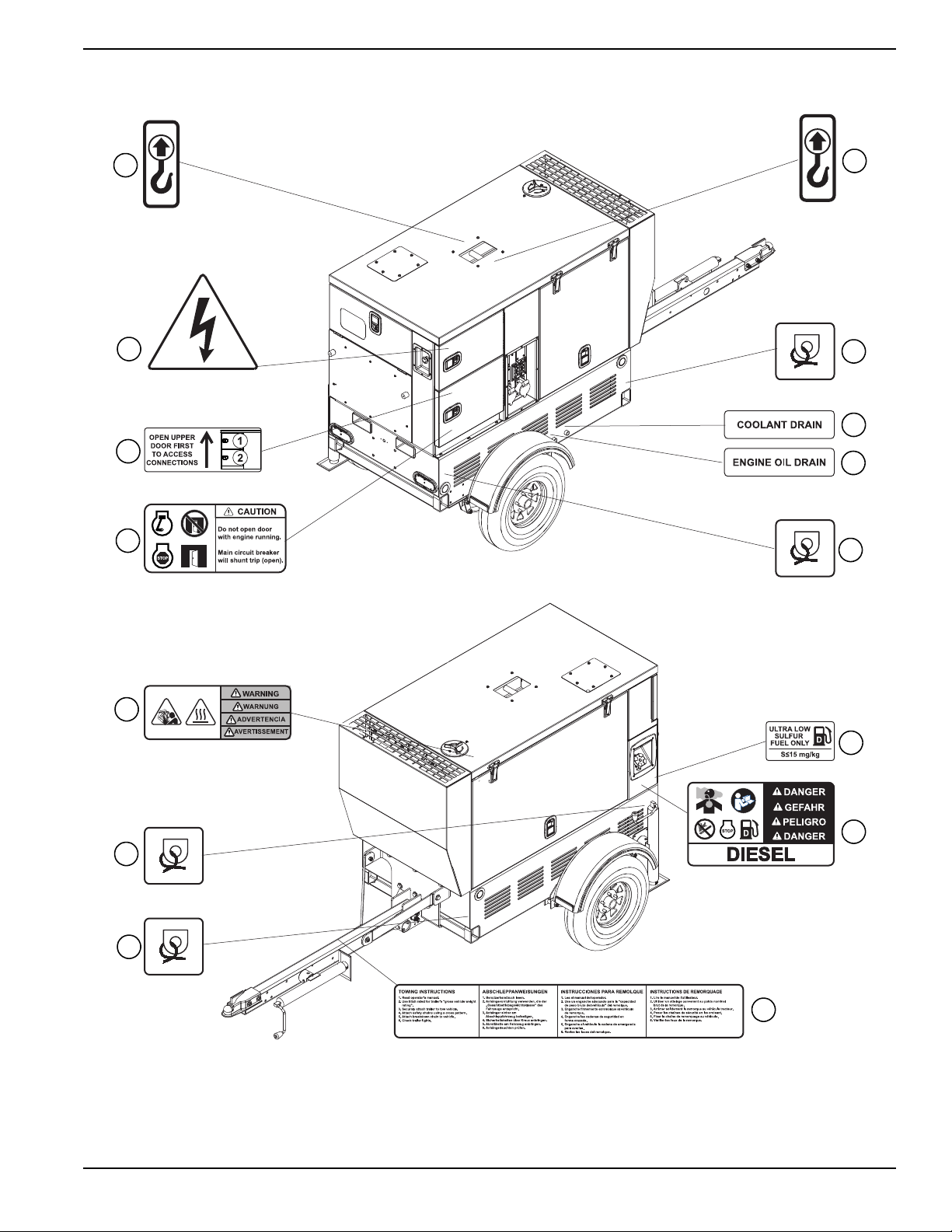
Safety and Operating Decals
This unit features numerous safety and operating decals.
These decals provide important operating instructions and
warn of dangers and hazards. The following diagrams
illustrate decal locations and descriptions.
Replace any missing or hard-to-read decals and use care
when washing or cleaning the unit. Decal part numbers
can be found in the parts manual at
www.generacmobileproducts.com.
Table 1-1. Decal Descriptions
ID Description
1 Lifting Point
2 Tie-Down Location
3 Coolant Drain
4 Engine Oil Drain
5 Ultra Low Sulfur Fuel Only
6 Diesel Fuel
7 Towing Instructions
8 Hot Coolant Under Pressure, Hot Surface
9 Do not Open Door with Engine Running
10 Open Upper Door First
11 Electric Shock Hazard
12 Warning
13 Moving Parts
14 Secondary Filter
15 Primary Filter
16 Battery Disconnect
17 Electrical Ground
18 Ground Output Connection
19 Starting and Stopping the Generator
20 Do not Open Door with Engine Running
21 Terminal Connections (Voltage Selector Switch)
22 CAN Lock Connectors
23 Connection Terminal Lugs
24 Remote Start Terminal Connections
25 Circuit Breaker
26 Electrical Backfeed Danger
27 Operating Instructions
28 Read and Understand Owner’s Manual
29 Buttons Below Controller
30 Neutral
31 Neutral Bonded to Frame
6 Owner’s Manual for MDG25IF4
Page 11
Introduction and Safety
1
11
10
9
8
7
6
5
2
4
3
2
007607
2
2
1
Figure 1-1. Exterior Decals
Owner’s Manual for MDG25IF4 7
Page 12
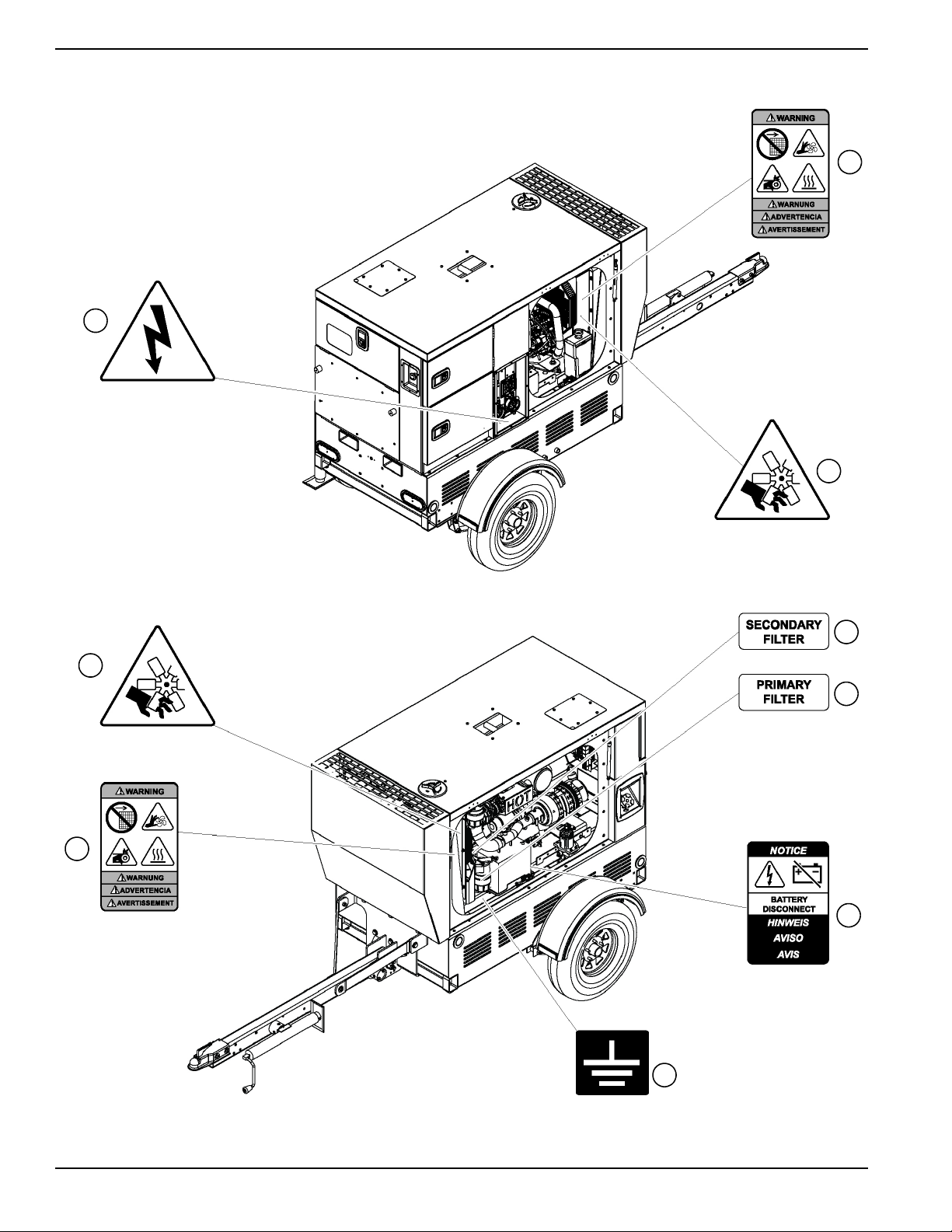
Introduction and Safety
007608
12
13
11
13
14
15
16
17
12
Figure 1-2. Interior Decals
8 Owner’s Manual for MDG25IF4
Page 13
10000023204
NEUTRAL (L0) BONDED TO FRAME
NULLLEITER (L0) AM RAHMEN ANGESCHLOSSEN
NEUTRO (L0) CONECTADO AL BASTIDOR
POSITION NEUTRE
(L0)
LORSQUE FIXÉ AU CADRE
29
28
27
26
24
18
22
21
20
19
007609
23
23
23
25
30
31
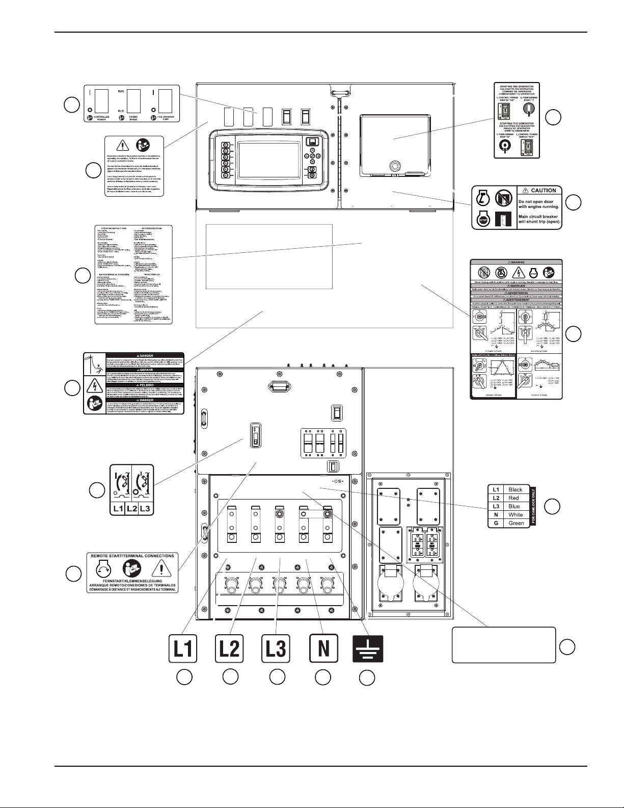
Introduction and Safety
Figure 1-3. Control Panel Decals
Owner’s Manual for MDG25IF4 9
Page 14

Introduction and Safety
This page intentionally left blank.
10 Owner’s Manual for MDG25IF4
Page 15

Section 2: General Information
Specifications
Description Units MDG25DF4
Engine
Make —
Model — 4LE2T
EPA Tier — Tier 4 Final
Rated Engine Power Output hp (kW) 33.5 (25)
Engine Speed rpm 1800
Fuel consumption—100%: Standby / Prime gph (Lph) 2.3 (8.6) / 2.0 (7.4)
Fuel consumption—75%: Standby / Prime gph (Lph) 1.7 (6.5) / 1.6 (6.1)
Fuel consumption—50%: Standby / Prime gph (Lph) 1.2 (4.4) / 1.1 (4.2)
Battery voltage V (quantity per unit) 12 (1)
Battery rating CCA 720
Isuzu
General Information
®
Generator
Make — Marathon Electric
Model — 282PSL1705
Power output 3Ø standby kW (kVA) 25 (31)
Current output 3Ø standby - 480V (208V) A 37 (86)
Power output 3Ø prime kW (kVA) 20 (25)
Current output 3Ø prime - 480V (208V) A 30 (70)
Power output 1Ø standby kW (kVA) 25 (25)
Current output 1Ø standby - 240V A 104
Power output 1Ø prime kW (kVA) 20 (20)
Current output 1Ø prime - 240V A 83
Power Factor kW (kVA) 1 (1Ø) / 0.8(3Ø)
Frequency Hz 60
Weights
Dry weight—skid mounted lb (kg) 1,977 (896)
Operating weight—skid mounted lb (kg) 2,373 (1,076)
Dry weight—trailer mounted lb (kg) 2,246 (1,018)
Operating weight—trailer mounted lb (kg) 2,642 (1,198)
Capacities
Usable fuel gal (L) 48 (181)
Coolant system gal (L) 4.4 (16.7)
Oil qts (L) 11 (10.4)
Maximum run time hours 24
AC Distribution
Circuit breaker size A 125
Owner’s Manual for MDG25IF4 11
Page 16
General Information
A
B
C
A
B
C
008731
Description Units MDG25DF4
Specifications are subject to change without notice. Refer to the product specification sheet for complete list.
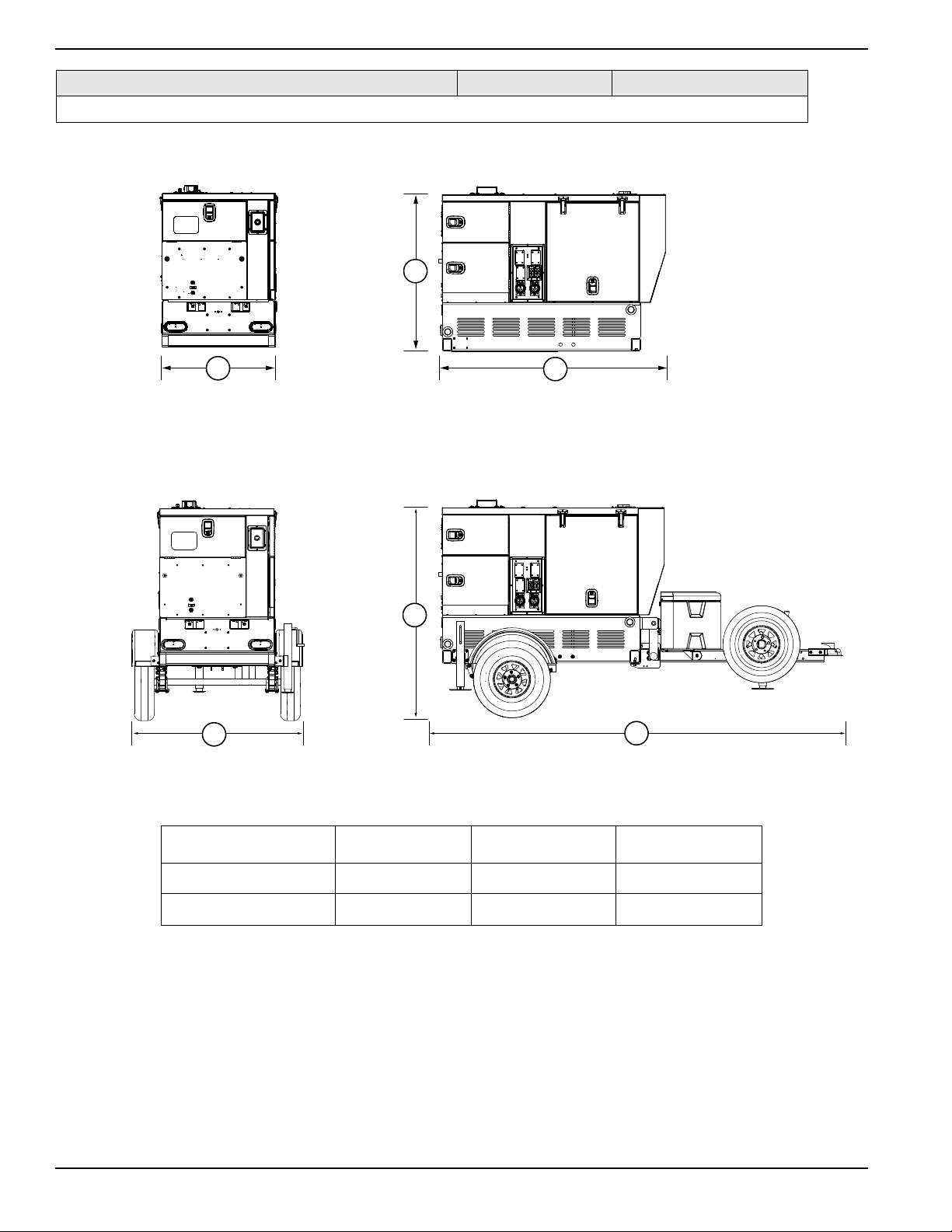
Unit Dimensions
Figure 2-1. Unit Dimensions
AB C
Skid Mounted 35 in (0.89 m) 48 in (1.22 m) 70 in (1.78 m)
Trailer Mounted 53 in (1.35 m) 65 in (1.65 m) 129 in (3.28 m)
12 Owner’s Manual for MDG25IF4
Page 17

Component Locations
J
008734
C
N
E
D
F
G
H
B
A
I
M
K
L
General Information
Figure 2-2. Component Locations
A Central Lift Point H Alternator
B Fuel Fill I Manual Holder
C Air Filter J Coolant Overflow Container
D Generator (located behind air filter) K Oil Drain
E Battery L Coolant Drain
F Primary Fuel Filter M Control Panel
G Secondary Fuel Filter N Fork Pockets
Owner’s Manual for MDG25IF4 13
Page 18

General Information
007612
A
B
H
G
D
E
F
C
Control Panel
Figure 2-3. Control Panel (rear of unit)
A Voltage Selector Switch E Option
B Emergency Stop Button F Option
C
PowerZone
®
Controller
G
Run/Idle Switch
D Power Switch H Fuel Transfer Pump Switch
14 Owner’s Manual for MDG25IF4
Page 19

General Information
007613
A
B
C
D
E
F
H
G
I
J
K
L
Figure 2-4. Control Panel (right side of unit)
A Main Circuit Breaker I Cam Lock Connection Lugs (5) (if equipped)
B Control Panel Lights (3) J Ground Connection Lug
C 50A Circuit Breakers (2) K Connection Lugs
D Service Lights Switch L Remote Start Terminal Block
E 20A Circuit Breakers (2)
F Lug Door Safety Switch
G 120V GFCI Receptacles (2)
H 120V/240V Twist-Lock Receptacles (2)
Owner’s Manual for MDG25IF4 15
Page 20

General Information
B
A
007614
Unit and Serial Number Locations
See Figure 2-5 to locate the unit ID tag (A) and vehicle
identification number (VIN) tag (B). Important information
such as the unit model number, serial number, VIN, and
tire loading information are listed on these tags. Record
the information from these tags in the event the tags are
lost or damaged. This information may be needed when
ordering parts or requesting assistance.
Figure 2-5. Unit and Serial Number Locations
Altitude and Temperature Limitations
All units are subject to derating for altitude and
temperature. Derating reduces the available power for
operating tools and accessories connected to the outlets.
For the MDG25, the engine can provide full prime power
up to an altitude of 10,000 ft (3048 m). The maximum air
temperature at which the unit can provide full prime
power is defined in Table 2-2. If the unit is operated
beyond this limit at full power, the coolant temperature
will exceed the maximum allowable limit of 235°F (113°C)
and cause the engine to shut down.
Table 2-2. Altitude and Temperature Limitations
Model
MDG25
Maximum Altitude
Prime
Power
10,000 ft
(3048 m)
Standby
(1371 m)
Power
4500 ft
Maximum Air
Temp erature
111 ° F
(44 °C)
16 Owner’s Manual for MDG25IF4
Page 21

General Information
A
007615
B
C
D
E
F
G
H
I
J
K
L
M
N
PowerZone® Controller
The PowerZone controller is an auto start controller that
monitors the unit and indicates operational status and
fault conditions. The controller can be programmed to
automatically start or stop based on time schedule, fault
condition, or load demand.
The controller constantly monitors vital generator and
engine functions for a number of preprogrammed alarm
and fault conditions. When a fault condition occurs, the
engine can shut down automatically and the display
screen will show the fault that caused the shut down. The
fault condition must be resolved to resume unit operation.
This controller records a history of unit performance,
which may be viewed at any time and will not be lost
when the controller is powered down.
NOTE: See Controller Features and Functions for
descriptions of the callouts below.
Figure 2-6. PowerZone Controller Layout
A Fuel Transfer Pump Switch H Voltage Adjust Button
B Engine Speed Switch I Generator Button
C Navigation Buttons J Engine Button
D Engine START Button K Home Button
E Engine STOP Button L Controller Power Switch
F AUTO or MANUAL Mode Button M N/A
G Alarm Mute Button N N/A
Owner’s Manual for MDG25IF4 17
Page 22

General Information
GEN
WARNING
Personal injury. Press the emergency stop button to
stop the engine immediately in case of an emergency.
Failure to do so could result in death or serious injury.
(000298a)
CAUTION
(000246)
Equipment Damage. The emergency stop switch is
not to be used to power down the unit under normal
operating circumstances. Doing so will result in
equipment damage.
Manual Mode
3 PHASE
Volts
Amps
480
128
%
0
10
100
110
20
30
40
50
60
70
80
90
Time to Empty
15 hr
Full
3/4
1/2
1/4
Empty
74
%
GEN
V
+
-
002787
Controller Features and Functions
These buttons are used to enter the various operator
screens from any other screen. The operator screens
consist of four screens: Home ( ), Engine ( ),
V
Generator ( ), and Voltage Adjust ( ). See
Operator Screens.
Fuel Transfer Pump Switch
Used to allow fuel into the engine.
Engine Speed Switch
Provides engine overspeed protection.
Navigation Buttons
Used to navigate through the various operator screens.
Engine START Button
Press the engine START (I) button while the controller is
in MANUAL mode to start the unit. If there are no
shutdown errors and the engine satisfies the start status
the unit will start. If the controller is in AUTO mode, the
engine START (I) button has no effect.
Engine STOP Button
-
+
Generator Button
Press to display the Generator Screen.
Engine Button
Press to display the Engine Screen.
Home Button
Press to display the Home Screen.
Controller Power Switch
Use this switch to start up and shut down the controller.
This switch should not be turned off when the unit is
running.
Operator Screens
The operator screens display the most relevant and
critical information needed to properly configure and
utilize a unit. From these four screens, the operator can
access the engine, generator, and power transmission
information necessary to operate the unit under normal
conditions.
Home Screen
The home screen is the controller’s default screen and
automatically displays after the controller is powered up
and the unit management software is loaded. It displays
a live readout of the kW meter, percent of load used
(gauge), selected phase, volts and amps being produced
by the generator, and the fuel level with time until empty.
The controller will automatically return to this screen from
any other screen after a period of inactivity.
Press the engine STOP (O) button to shut down the unit
and put the controller into STOP mode, whether in
MANUAL mode or AUTO mode.
AUTO or MANUAL Mode Button
Changes the startup and shutdown modes of the unit.
The unit enters MANUAL mode when pressed once. The
unit enters AUTO mode when pressed and held for five
seconds. If in AUTO mode, pressing once will return the
unit to MANUAL mode.
Alarm Mute Button
Silences the audible alarm. Additional action will be
required to fully disable the active alarm.
Voltage Adjust Button
Press to display the Voltage Adjust Screen.
18 Owner’s Manual for MDG25IF4
Figure 2-7. Home Screen
Engine Screen
The engine screen displays the oil pressure, coolant
temperature, and battery voltage on three main gauges.
An hour gauge displaying the total run time on the engine
is below the gauges. The hour gauge also displays
maintenance alarm status at the bottom of the screen,
with the time remaining (black text) or the time passed
(red text), a scheduled maintenance task, along with the
description of the maintenance procedure, and the action
that will take place when the timer trips the alarm.
Page 23

General Information
002788
Manual Mode
GEN
V
+
-
Parallel Low Zig-Zag
L1 (U)
L2 (W)
N
Volt Volt Amp kW
L1-L2 L1
L2-L3 L2
L3-L1 L3
IE
0
0
0
0
0
0
0
0
50
25
0.0
0.0
0.0
AmpVolt
Freq
0
10
20
30 40
50
60
70 0
88
175
263
350 0
13
25
38
50
002789
Manual Mode
40 60
20
80
170
190 210
230
20 30
10
40
50.9
100
PSI
0 0 3 2 5 1 5
214
0
250
°F
Hrs
13.8
V
Shutdown
Electrical Trip
50150
Warning
0
GEN
Oil press. Coolant Temp. Battery
V
-
+
Maintenance
Alarm Hours Description Action
1 174 To Service Oil Maintenance
2 174 To Service Fuel Maintenance
3 174 To Service Air Maintenance
Figure 2-8. Engine Screen
NOTE: If the measured value is outside the range of a
gauge, the needle will not be displayed. The digital value
below the gauge will still show the measured value.
• Oil Press: Displays engine oil pressure. Current
coolant temperature displays directly below the
gauge at all times. The gauge registers oil pressure
between 0–100 psi (0–689 kPa). Normal operating
pressure is between 35–80 psi (241–552 kPa).
• Coolant Temp: Displays engine coolant
temperature. Current coolant temperature displays
directly below the gauge at all times. The gauge
displays coolant temperature between 150–250 °F
(66–121 °C). Normal operating temperature of the
unit is between 180–200 °F (82–93 °C) with an
average ambient air temperature of 70 °F (21 °C).
• Battery: Displays the engine battery voltage.
Current battery voltage displays directly below the
gauge at all times. The gauge displays battery
voltage between 0–50V. A normal reading is 12–
14V on 12 volt systems and 24–26V on 24 volt
systems (with the engine running).
Generator Screen
The generator screen displays the average voltage
frequency, volts and amps from the generator, as well as
line-to-line voltage, and individual line-to-neutral voltage,
amperage, and power (kW). This screen also displays
the generator winding configuration set by the voltage
selector switch in the lower right corner.
Figure 2-9. Generator Screen
NOTE: When loading the generator, it is important to
observe the amperage to determine the load balance on
each line of the generator. Minor load imbalances,
usually 10% or less, will not cause problems. Every effort
should be made to distribute the load equally between all
lines.
• Freq: Displays the output frequency in Hertz (Hz).
Normal operating frequency is 60 Hz.
• Volt s: Displays the nominal voltage in volts (V).
• Amps: Displays the AC output amperage
produced by the generator in amps (A).
Additional information can be found on the electric power
table at the bottom-left side of the screen. This provides
an overview of all three lines and average voltage and
amperage readouts.
Voltage Adjust Screen
The unit automatically fine tunes voltage upon start-up
after the output voltage is selected and the unit is started.
See Voltage Selector Switch. The voltage can be
manually fine tuned as needed. See Fine Voltage
Adjustment.
The voltage adjust screen displays the line-to-neutral and
line-to-line voltage averages. The operator can
electronically adjust the voltage within limits to prevent
under-voltage or over-voltage conditions using the onscreen instructions. This feature replaces a traditional
potentiometer.
Owner’s Manual for MDG25IF4 19
Page 24

General Information
Manual Mode
GEN
V
+
-
Voltage Adjust
- Press , voltage will begin flashing
- Use and arrows to adjust voltage
- Press to confirm new voltage. Numbers will stop flashing
V
L-N Average
L-L Average
V
277
480
002803
SITE GENSET
07:10
480V/277V 3-Phase
Return Delay 10:00:00
Total
kWh+
kVAh
kVArhpf
kVAr
kVA
kW
%
0.0
0.0
0.0
%
0.0
0.0
0.0
0.0
0.00
0.0
0.0
Hz
kW
kVAr
Energy Generator
002790
GEN
V
+
-
SITE GENSET
7741 \ 7740
07:10
480V/277V 3-Phase
Status
Schedule
I/O
AlarmsEngine Generator
1/9
Engine Starts
Fuel Used
Fuel Remaining
US Gal
Litre
Hrs
RPM
0
00000 00
Oil press. Coolant Temp.
Charge AltBatteryOil Temp
Fuel Level
0
°F V
%
0
°FPSI
0.0
V
0.0
00.00
0
10
20 30
40
50
0
10
20 30
40
50
0
2
46
8
10 -50
0
50 150
200
250 0
20
40 60
80
100
10
30
90
70
50
1
3
5
7
9
100
-50
0
50 150
200
250
100
CAN
0
3
6
9
12 15
18
21
24
27
15
30
33
36
007616
GEN
V
+
-
SITE GENSET 7741 \ 7740
07:10
480V/277V 3-Phase
StatusSchedule
I/O
AlarmsEngine
Generator
1/9
L1-L2
L2-L3
L3-L1
L1
L2
L3
IE
Volt Volt Amp kW kVA kVAr pf
0.0
0.0
0.0
0.0
0.0
0.0
0.0
0.0
0.0
0.0
0.0
0.0
0
0
0
0
00
0
0
0
0
L1-L2 L2-L3 L3-L1 Hz
FreqVoltVoltVolt
0
100
200
300
400
500
600
0
100
200
300
400
500
600 0
100
200
300
400
500
600 0
10
20
30 40
50
60
70
007617
Figure 2-10. Voltage Adjust Screen
Maintenance Screens
All of the data inputs from the engine, generator, inputs/
outputs, schedule, and PowerZone controller are visible
on the maintenance screens.
The information displayed on the maintenance screens
can be used to identify, diagnose, and troubleshoot unit
shutdown conditions and poor unit performance. The
maintenance screens can be accessed from any
operator screen by pressing any directional arrow (▲, ►,
▼, ◄).
The bottom of the screens have a list of available tabs,
with the currently displayed tab highlighted in blue. The
tabs can be selected by using the ► or ◄ buttons. The
current/available pages are displayed to the left of the
tabs. The pages within a tab can be viewed by using the
▲ and ▼ buttons. Whenever a new tab is selected, the
current page will always be page one.
Generator Summary
The generator summary can be found at the top of all
maintenance screens and provides an overview of the
system.
Engine Tab
The engine tab contains maintenance and
instrumentation data gathered from the engine. Above
the engine analog meters is a row of alarm icons. Each
icon can be one of three colors: gray (inactive), yellow
(warning), or red (shutdown). The alarm icons from left to
right are: water in fuel, emission filter, engine air inlet
temperature, charge alternator, oil pressure, fuel level,
battery voltage, coolant temperature, and ECU lamp.
NOTE: The content may change depending upon the
selected engine and the features supported by the
engine.
Figure 2-12. Engine Tab Screen
Generator Tab
The generator tab contains maintenance and
instrumentation data gathered from the generator. Each
page highlights different data gathered by the generator,
with the analogue meters changing accordingly. The last
two pages display the information in the bar graph. The
bar graph is blue for positive and red for negative. For the
power factor bar graph, blue is for lagging pf and red is
for leading pf.
NOTE: The content may change depending upon the
selected generator and the features supported by the
generator.
Figure 2-11. Generator Summary Screen
20 Owner’s Manual for MDG25IF4
Figure 2-13. Generator Tab Screen
Page 25

Alarms Tab
GEN
V
+
-
SITE GENSET 7741 \ 7740
07:10
480V/277V 3-Phase
Return Delay 10:00:00
0.0
Hz
Total Generator
kWh+
kVAh
kVArh
kW
kVA
kVAr
pf
0.0
0.0
0.0
0.0
0.0
0.0
0.00
0.0
%
%
0.0
kW
kVAr
StatusSchedule
I/O
AlarmsEngine Generator
1/2
Warning Shutdown Electrical Trip
Engine
002793
GEN
V
+
-
SITE
GENSET
7741 \ 7740
07:10
480V/277V 3-Phase
Return Delay 10:00:00
0.0
Hz
Total Generator
kWh+
kVAh
kVArh
kW
kVA
kVAr
pf
0.0
0.0
0.0
0.0
0.0
0.0
0.00
0.0
%
%
0.0
kW
kVAr
Status
Schedule
I/O
AlarmsEngine Generator
2/2
Warning
Shutdown
Shutdown
Shutdown
Shutdown
Shutdown
Shutdown
Shutdown
Shutdown
Shutdown
Shutdown
Shutdown
Shutdown
This is an event index 1
This is an event index 2
This is an event index 3
This is an event index 4
This is an event index 5
This is an event index 6
This is an event index 7
This is an event index 8
This is an event index 9
This is an event index 10
This is an event index 11
This is an event index 12
This is an event index 13
1 01/01/1970 00:00:01 0:00
2 02/06/1970 11:45:55 0:00
3 01/01/1970 00:00:00 0:00
4 01/01/1970 00:00:00 0:00
5 01/01/1970 00:00:00 0:00
6 01/01/1970 00:00:00 0:00
7 01/01/1970 00:00:00 0:00
8 01/01/1970 00:00:00 0:00
9 01/01/1970 00:00:00 0:00
10 01/01/1970 00:00:00 0:00
11
12 01/01/1970 00:00:00 0:00
13 01/01/1970 00:00:00 0:00
01/01/1970 00:00:00 0:00
Index Date Time Hrs Event Details
002794
GEN
V
+
-
SITE GENSET 7741 \ 7740
07:10
480V/277V 3-Phase
Return Delay 10:00:00
0.0
Hz
Total
Generator
kWh+
kVAh
kVArh
kW
kVA
kVAr
pf
0.0
0.0
0.0
0.0
0.0
0.0
0.00
0.0
%
%
0.0
kW
kVAr
StatusSchedule
I/O
AlarmsEngine Generator
1/38
Digital Inputs
Ip Description Active State Ip Description Active State
A
B
C
D
E
F
H
I
J
G
K
002795
The alarms tab displays warnings, electrical trip,
shutdown alarms, and any engine diagnostic trouble
codes (DTC) that are occurring or have occurred. The
first page displays the alarms that are currently active
and organizes them by alarm type.
Figure 2-14. Alarms Tab Screen (Page One)
General Information
Figure 2-15. Alarms Tab Screen (Page Two)
To scroll down within the event log, press the ENTER ()
button. The scroll bar will activate and change to blue.
Press the ▲ or buttons to scroll up or down in the
event log. Press the ENTER () button again when
finished.
Table 2-3. Diagnostic Trouble Codes
Alarm
Typ e
Warning Yellow/Black
Electrical
Trip
Shutdown Red/Black
ECU
Code
Color–
Background/Text
Purple/Black
Blue/White
Graphic
Warning
Electrical Trip
Shutdown
Engine
The second page of the alarms tab shows the event log
with a list of events, including normal operation events
and alarm notifications. The most recent events are listed
first. All indexed events include the date and time of the
event, and hours of runtime on the engine when it
occurred, along with the event name or alarm type and
details.
Input/Output Tab
The input/output (I/O) tab shows a list of digital inputs and
outputs connected to the controller, whether they are
active or not, and the current state (open/closed status)
of the input and output.
Figure 2-16. Input/Output Tab Screen
Owner’s Manual for MDG25IF4 21
Page 26

General Information
GEN
V
+
-
SITE GENSET 7741 \ 7740
07:10
480V/277V 3-Phase
Return Delay 10:00:00
0.0
Hz
Total Generator
kWh+
kVAh
kVArh
kW
kVA
kVAr
pf
0.0
0.0
0.0
0.0
0.0
0.0
0.00
0.0
%
%
0.0
kW
kVAr
StatusSchedule
I/O
AlarmsEngine Generator
1/1
Warning
Warning
Warning
ActionDescription
Alarm Hours Date Time
Maintenance
Scheduler Enabled to run Reserved Reserved
Event Week Day Start Stop Duration Event Week Day Start Stop Duration
250 hr Maint. - Refer to Manual
500 hr Maint. - Refer to Manual
3000 hr Maint. - Refer to Manual
1 250:00
2 500:00
3 3000:00
All Monday 00:00 00:00 0:00
All Monday 00:00 00:00 0:00
All Monday 00:00 00:00 0:00
All Monday 00:00 00:00 0:00
All Monday 00:00 00:00 0:00
All Monday 00:00 00:00 0:00
All Monday 00:00 00:00 0:00
All Monday 00:00 00:00 0:00
9
10
11
12
13
14
15
16
All Monday 00:00 00:00 0:00
All Monday 00:00 00:00 0:00
All Monday 00:00 00:00 0:00
All Monday 00:00 00:00 0:00
All Monday 00:00 00:00 0:00
All Monday 00:00 00:00 0:00
All Monday 00:00 00:00 0:00
All Monday 00:00 00:00 0:00
1
2
3
4
5
6
7
8
002796
GEN
V
+
-
SITE GENSET 7741 \ 7740
07:10
480V/277V 3-Phase
Return Delay
10:00:00
0.0
Hz
Total Generator
kWh+
kVAh
kVArh
kW
kVA
kVAr
pf
0.0
0.0
0.0
0.0
0.0
0.0
0.00
0.0
%
%
0.0
kW
kVAr
StatusSchedule
I/O
AlarmsEngine Generator
1/1
- DCD
- DSR
- DTR
- RTS
- CTS
Model
Link Quality
100%
Application
USB ID
Supervisor State:
Engine State:
Load State:
Protections:
Logging
Log Dest:
Log Mode:
USB drive:
Host IP:
Host Port:
Slave IP:
Slave Port:
Total mem
Log mem free
Log Time:
Bootloader
Analogue
Engine:
Model
Application
USB ID
Bootloader
Ethernet
002797
WARNING
Electric Shock. Never change the voltage
selector switch while the engine is running or
the controller is on. Doing so could result in
death, serious injury or equipment
damage.
(000302)
Scheduler Tab
The scheduler tab shows the current configuration and
status of the scheduler, located below the generator
summary. The maintenance configuration status and time
remaining until an alarm, electrical trip, or shutdown will
be displayed at the bottom of the screen. The lamp(s) to
the left shows the configuration status of the
maintenance alarm, not the alarm condition.
Figure 2-17. Schedule Tab Screen
Status Tab
Engine Monitoring
Engine information is displayed on both the engine
operator screen and engine tab within the Maintenance
Screens. See Engine Tab.
PowerZone Controller Information Displays, Functions, and Reset
The PowerZone controller constantly monitors vital
generator and engine functions for a number of
operation, alarm, and fault conditions. When a fault
condition occurs, the engine shuts down automatically
and the main display shows the fault that caused the
shutdown. The fault condition must be resolved to
resume operation. Press the ENTER () button to reset
the controller and resume operation.
Voltage Selector Switch
The status tab contains the status and configuration of
the controller, firmware, and data connections.
Figure 2-18. Status Tab Screen
Generator Monitoring
Generator information is displayed on both the generator
button screen and generator tab within the Maintenance
Screens. See Generator Tab.
The voltage selector switch mechanically configures the
main windings of the generator to provide a Hi Wye, Low
Wye, Zig Zag or Delta (if equipped) configuration
providing single and three phase voltage output to the
main breaker. Voltage ranges are selected by rotating the
handle on the switch to the desired voltage.
The voltage selector switch is equipped with a lockout
mechanism to prevent unauthorized changing of the
voltage setting by locking the handle in place.
See Using the Voltage Selector Switch for instructions
on switching the voltage.
22 Owner’s Manual for MDG25IF4
Page 27

Section 3: Operation
(000100a)
WARNING
Consult Manual. Read and understand manual
completely before using product. Failure to
completely understand manual and product
could result in death or serious injury.
CAUTION
(000291)
Equipment damage. Do not attempt to start or operate
a unit in need of repair or scheduled maintenance.
Doing so could result in serious injury, death, or
equipment failure or damage.
WARNING
(000147)
WARNING
Risk of Fire. Unit must be positioned in a
manner that prevents combustible material
accumulation underneath. Failure to do so
could result in death or serious injury.
Asphyxiation. Running engines produce
carbon monoxide, a colorless, odorless,
poisonous gas. Carbon monoxide, if not
avoided, will result in death or serious injury.
(000103)
DANGER
WARNING
Fire risk. Fuel and vapors are extremely
flammable. Do not operate indoors. Doing so
could result in death, serious injury, or
property or equipment damage.
(000281)
82%
Image File Transer...
002804
Operation
Pre-start Checklist
All items in the pre-start checklist must be completed
before starting the unit. This checklist applies to both
manual and remote starting of the unit.
Verify all maintenance procedures are up to date. For
more information, see General Maintenance and
Basic Maintenance Schedule.
Verify the unit is level.
Verify there is no water inside, on, or near the unit;
dry if needed.
For grounding requirements, follow any local, state,
or National Electrical Code (NEC) guidelines.
Verify the control power switch is OFF (O).
Verify all circuit breakers are OFF (O).
Inspect all electrical cords; repair or replace any that
are cut, worn, or bare.
Verify oil, coolant, and fuel levels are correct, per the
engine manufacturer’s manual.
Verify battery connections are secure.
Turn the battery disconnect switch ON (if equipped).
Verify engine fan belt tension and condition are within
spec.
Verify engine fan belt guard is installed and secure.
Check engine exhaust system for loose or rusted
components.
Verify the radiator and surrounding shroud are clear
of debris.
Verify all covers are in place and secure.
Owner’s Manual for MDG25IF4 23
Verify all electrical connections at the connection
lugs, if equipped, are tight and wired correctly.
Verify the voltage selector switch is set to the desired
voltage and locked.
Verify the emergency stop switch is pulled out.
Verify all doors on the unit are closed.
Manually Starting the Unit
All units equipped with the PowerZone controller will
initially start up in STOP mode. Proceed as follows to
start the generator in MANUAL mode:
1. Set the control power switch to ON (I).
2. The display screen will show the pre-start
diagnosis, and the controller will load the unit
management software.
Figure 3-1. Pre-start Screen
3. The home screen will be displayed when the
software is loaded, and the controller will be in
STOP mode as indicated at the top of the screen.
Press the AUTO or MANUAL mode ( ) button to
enter MANUAL mode.
Page 28

Operation
Stop Mode
3 PHASE
Volts
Amps
0
0
0.0 kW
%
0
10
100
110
20
30
40
50
60
70
80
90
Time to Empty
15 hr
Full
3/4
1/2
1/4
Empty
74
%
GEN
V
+
-
002805
the generator, depending on the type of engine
governing used.
11. If all wiring connections have been made correctly,
switch the main circuit breaker to ON (I), and then
add any loads attached to the receptacles by
switching the respective circuit breaker to the ON
(I) position. A slight change in engine sound when
a load is applied to the unit is normal.
AUTO (Remote) Starting the Unit
AUTO mode is used when the unit is started from a
location other than the control panel by using a transfer
Figure 3-2. Home Screen
NOTE: The controller can be started from any screen
when it is in MANUAL mode.
4. Pressing the green engine START (I) button on the
controller will initiate the startup procedure and
start the engine, if there are no engine faults
preventing the unit from starting.
NOTE: It may take a few seconds for the engine to run
smoothly and reach its governed operating speed. During
this time, the screen will show a voltage different from the
voltage set with the voltage selector switch.
5. If the engine does not start after the first cranking
attempt, the engine will pause for 15 seconds to
allow the starter to cool. The display screen will
show MANUAL MODE - CRANK REST at the top
of the screen. The engine will make two more
attempts to start for a total of three crank cycles.
6. If the engine does not start and run within three
crank cycles, the display screen will show the fail to
start alarm. The starting sequence can be repeated
after the starter has had a minimum of two minutes
to cool. Pressing the ENTER () button will clear
the alarm and reset the controller.
NOTE: The engine controller may skip the preheat
engine steps on some of the larger models.
7. Once the engine starts, it begins speeding up to a
constant 1800 RPM. The engine may hunt or
change speeds until operating speed is reached.
The engine will be warmed up and the operator
screens will show engine and generator operating
parameters after a few minutes of operation.
8. Check the generator for excessive noise or
vibration and any coolant, oil, or fuel leaks before
applying any loads.
9. Verify the AC output voltage is correct. See Fine
Voltage Adjustment.
10. Verify the frequency (Hz) is correct on the
24 Owner’s Manual for MDG25IF4
generator screen. The frequency should read
approximately 60 Hz with no loads connected to
switch. AUTO (remote start) is the normal setting when
the unit is being used as a standby power supply. Review
the Pre-start Checklist and Manually Starting the Unit
before putting the unit in AUTO mode. Follow all safety
warnings and review all information on isolating the
generator with a transfer switch if the unit is to be used as
a standby power supply. See AUTO Exercise Timer,
then proceed as follows:
1. Perform a manual start of the unit at least once to
verify the engine is operating correctly.
2. To check the remote start circuit, remove the wires
from the remote start terminal block. Press the
AUTO or MANUAL mode ( ) button, and the
display screen will show auto mode at the top of
the screen.
3. Attach a jumper wire (minimum 16 gauge) across
the two terminals on the remote start terminal
block. This applies a ground to the PowerZone
controller to close the starting circuit contacts. The
engine will crank, start, and run.
4. Remove the jumper wire from the remote start
terminal block and the engine will stop. Reconnect
any necessary wires from the remote start switch
(transfer switch) to the remote start terminal block.
5. Verify the unit is in AUTO mode. The display
screen should show AUTO mode at the top of the
screen.
6. Switch the main circuit breaker ON (I).
7. Secure the unit by closing and locking all access
doors.
8. The unit is now ready for remote starting.
See Figure 3-3. The remote start terminal block provides
a connection for installation of a remote start switch
which will allow the unit to be started by a remote drycontact closure switch. For location of the remote start
terminal block, see Figure 2-4.
Before entering AUTO mode, verify the contacts on any
remote switch linked to the unit are open. If the contacts
on a remote switch are closed, the engine will crank and
start when AUTO mode is entered. Attach the switch
leads to the two unused terminals (A) on the unit’s
remote start terminal block.
Page 29

Figure 3-3. Remote Start Terminal Block
A
002806
DANGER
Explosion. Do not use ether when starting an
engine equipped with glow plugs or an air intake
heater. Doing so could cause an explosion, which
will result in death or serious injury.
(000583)
008744
Wet Stacking
The unit is powered by a diesel engine. Diesel engines
are susceptible to wet stacking if lightly loaded. Wet
stacking occurs when an engine is run at less than 30%
of its full load capacity, causing unburned fuel to
accumulate in the exhaust system. Wet stacking can be
detected by continuous black exhaust when the unit is
under a constant load. It can also cause fouling of
injectors and buildup on engine valves. Diesel engines
operate properly when applied loads are between 30%
and 100% capacity. Appropriate generator sizing is
determined by the anticipated load. If the unit is in a wet
stack condition, load the unit heavily for five hours or until
the exhaust is clear.
Operation
shore power 120V electrical connection that can be
found in the convenience receptacle. The crankcase
ventilation heater is powered by the generator and will
stay on when the engine is operating in cold weather
conditions.
Figure 3-4. Cold Weather Starting Guidelines
A No Aids
B Electric Air Heat
C Block Heat
D Ether
Cold Weather Operation
Use cold weather starting aids as needed according to
Figure 3-4. Follow supplier instructions for starting aids
provided on engine. A booster battery can be connected
if needed (see Using a Booster Battery or Charger (if
The engine may be equipped with optional equipment,
such as a coolant heater, oil pan heater, crankcase
ventilation heater, battery heater or fuel heater as cold
weather starting aids.
See Figure 3-4. Starting aids are required below
32°F (0°C). They will enhance starting performance
below these temperatures and may be needed to start
applications that have high parasitic loads during
cranking and start acceleration to idle. Other cold
weather starting aids are required at temperatures below
-13°F (-25°C) or at altitudes above 5000 ft (1500 m).
The use of correct grade oil (see Recommended Oil
Types) is critical to achieving adequate cold weather
cranking speed. Synthetic oils have improved flow at low
temperatures.
The oil pan heater, battery heater and fuel filter heater (if
equipped) are activated with a thermostat and will turn on
and off as needed. The coolant heater is powered by a
Owner’s Manual for MDG25IF4 25
equipped)).
NOTE: Turn key to ON but do not crank engine until
Engine Preheat Indicator goes off.
NOTE: Additional information on cold weather operation
is available from your local GMP ASD.
E Electric Air Heat and Block Heat
F Ether and Block Heat
Page 30

Operation
(000137a)
WARNING
Explosion. Batteries emit explosive gases while charging.
Keep fire and spark away. Wear protective gear when
working with batteries. Failure to do so could result in
death or serious injury.
(000138a)
WARNING
(000167a)
CAUTION
Equipment damage. Do not make battery
connections in reverse. Doing so will result
in equipment damage.
004507
004508
(000237)
DANGER
Electrical backfeed. Use only approved switchgear to
isolate generator from the normal power source.
Failure to do so will result in death, serious injury,
and equipment damage.
(000157)
DANGER
Electrocution. Do not disable or modify the
connection box door safety switch. Doing so
will result in death or serious injury.
Using a Booster Battery or Charger (if equipped)
See Figure 3-6. A 12 volt booster battery can be
connected in parallel with battery(ies) on the unit to aid in
cold weather starting. ALWAYS use heavy-duty jumper
cables.
Series:
• Amps = Same as single battery
• Volts = Twice as a single battery
Parallel:
• Amps = Twice as a single battery
• Volts = Same as single battery
Figure 3-6. Parallel
1. Connect booster battery or batteries to produce the
required system voltage.
NOTE: To avoid sparks, do not allow the free ends of
jumper cables to touch engine.
2. Connect one end of jumper cable to the POSITIVE
(+) post of the booster battery.
3. Connect the other end of the jumper cable to the
POSITIVE (+) post of battery connected to starter.
4. Connect one end of the other jumper cable to the
NEGATIVE (-) post of the booster battery.
5. Complete the hookup by making the last
connection of the NEGATIVE (-) cable to a good
ground on the engine frame and away from the
battery(ies).
6. Start the engine. Disconnect jumper cables
immediately after engine starts. Always disconnect
NEGATIVE (-) cable first.
Generator Output Connections
Figure 3-5. Series
26 Owner’s Manual for MDG25IF4
Page 31

The installation should be in compliance with the national
(000156)
DANGER
Electrocution. Before connections are made to
the unit, verify the main circuit breaker and
battery disconnect switch are OFF. Failure to do
so will result in death or serious injury.
(000155a)
WARNING
Electric shock. Only a trained and licensed electrician
should perform wiring and connections to unit. Failure
to follow proper installation requirements could result in
death, serious injury, and equipment or property damage.
007618
B
A
(000156)
DANGER
Electrocution. Before connections are made to
the unit, verify the main circuit breaker and
battery disconnect switch are OFF. Failure to do
so will result in death or serious injury.
(000237)
DANGER
Electrical backfeed. Use only approved switchgear to
isolate generator from the normal power source.
Failure to do so will result in death, serious injury,
and equipment damage.
WARNING
Electric Shock. Verify all connections to the
cam lock receptacles are made to one side
only. Failure to do so could result in death,
serious injury and property damage.
(000308)
(000155a)
WARNING
Electric shock. Only a trained and licensed electrician
should perform wiring and connections to unit. Failure
to follow proper installation requirements could result in
death, serious injury, and equipment or property damage.
L1
L2
L3
N (Neutral)
G (Ground)
Black
Red
Blue
White
Green
007619
A
electrical code (NEC), state, and local regulations.
See Figure 3-7. The unit is equipped with connection
lugs (A), located on the lower portion of the control box
behind the lug box door. The lugs provide connection
points to attach external loads to the generator. A large
decal on the inside of the connection lug door details the
proper connections for selected voltages.
Connections to the lugs should be made by running the
power cables up through the opening in the bottom of the
box.
Operation
Generator Cam Lock Connections (If Equipped)
IMPORTANT NOTE: Do not make any connections
directly to the lugs without routing the cables
through the opening. Use a hex-wrench to tighten the
cable connections.
The connection lug door is equipped with safety interlock
switches that will trip the main circuit breaker and disable
the voltage regulator if the door is opened while the unit
is operating.
A ground connection (B) is located next to the connection
lugs. The unit must be connected to ground for proper
operating safety. The generator neutral is bonded to
ground when it is shipped from the factory. The bonding
plate must be removed when the generator is used as a
standby power source.
See Figure 3-8. The unit may be equipped with cam lock
connections (A) located below the receptacles. These
receptacles provide connection points to attach external
loads to the generator. A decal below the cam lock
connections details the proper connections for selected
voltages.
Connections should be made by plugging power cables
equipped with series 16 taper nose 400A/600V cam lock
plugs into the cam lock receptacles. Secure the
connection by rotating the plug a 1/2 turn to the right.
Figure 3-7. Generator Connection Lugs
Owner’s Manual for MDG25IF4 27
Figure 3-8. Cam Lock Connections
Page 32

Operation
(000157)
DANGER
Electrocution. Do not disable or modify the
connection box door safety switch. Doing so
will result in death or serious injury.
WARNING
Electric Shock. Never change the voltage
selector switch while the engine is running or
the controller is on. Doing so could result in
death, serious injury or equipment
damage.
(000302)
Manual Mode
GEN
V
+
-
Voltage Adjust
- Press , voltage will begin flashing
- Use and arrows to adjust voltage
- Press to confirm new voltage. Numbers will stop flashing
V
L-N Average
L-L Average
V
277
480
002803
V
+
-
WARNING
Electric Shock. Never change the voltage
selector switch while the engine is running or
the controller is on. Doing so could result in
death, serious injury or equipment
damage.
(000302)
CAUTION
(000303)
Equipment Damage. Verify voltage application before
making changes to factory settings. Incorrect voltage
applied to a load could result in equipment damage.
A ground connection is located on the far right of the cam
lock panel. The unit must be connected to a good
earthen ground for proper operating safety. The
generator neutral is bonded to ground when it is shipped
from the factory. The bonding plate must be removed
when the generator is used as a standby power source.
Installation should be in compliance with the National
Electrical Code (NEC), state, and local regulations.
Using the Voltage Selector Switch
2. Press . The voltages displayed will flash.
3. Use ▲ and ▼ to adjust the voltage.
4. Press to confirm the new voltage. The voltages
displayed will stop flashing.
Voltage Regulator
The automatic voltage regulator controls the output of the
generator by regulating the current into the exciter field.
The voltage regulator is adjusted before shipment from
the factory. The regulator has four screwdriver adjustable
potentiometers that may be adjusted for under frequency
roll-off (U/F), U/F dip (DIP), stability (STAB), and voltage
(VOLT). Contact a GMP ASD for additional information
before attempting to adjust the voltage regulator.
NOTE: For units equipped with a Marathon DVR2000E+
automatic voltage regulator, see the Marathon operating
manual provided with the unit.
Achieving 240V Three-Phase in
1. Shut down the unit according to Shutting Down
the Unit.
2. Remove padlock from voltage selector switch
lockout device.
3. Move voltage selector switch to desired voltage.
4. Replace and lock padlock on voltage selector
switch lockout device.
5. Start the unit according to Manually Starting the
Unit or AUTO (Remote) Starting the Unit.
Fine Voltage Adjustment
See Voltage Adjust Screen for information on screen
display.
1. With the unit running, press .
28 Owner’s Manual for MDG25IF4
Figure 3-9. Voltage Adjust Screen
208V Three-Phase (Parallel Low
Wye) Configuration
IMPORTANT NOTE: Using this method to achieve
240V 3Φ will result in a line to neutral voltage of 139V,
and is not recommended for single phase usage.
Proceed as follows to check which version of the
PowerZone controller application the unit has:
1. With the unit shut down, set the control power
switch to the ON (I) position. The controller will
toggle automatically to the home screen after
initialization.
2. Press ▲, ►, ▼, or ◄ to enter the maintenance
screens.
3. Press ► until the status tab is selected. This tab
will display which version of the PowerZone
application the unit has.
NOTE: The version is also displayed in the top left
corner of the Configuration menu. See Accessing the
Configuration Menu.
Page 33

Operation
CAUTION
(000303)
Equipment Damage. Verify voltage application before
making changes to factory settings. Incorrect voltage
applied to a load could result in equipment damage.
After verifying the unit has V4 or higher of the PowerZone
controller application, proceed as follows to achieve
240V while in the 208V configuration:
4. Starting in any of the operator screens, press ▲,
►, ▼, or ◄ to enter the maintenance screens.
5. Press and O simultaneously. The next screen
will display the configuration menu.
6. Press ▼ to move the cursor (blue highlighted text)
down to Config Selection.
7. Press ► to highlight Config to Edit. Press ► again
to highlight Selected Configuration. Then press
to access the selections.
8. Press ▲ to highlight Alternative Configuration 1.
Press .
9. Press ◄ two times to get back to the far left
column.
10. Press ▼ to highlight Password Entry. Press to
display the Pin Entry screen. Press again to
access to password entry. The left most pound sign
should change to 0.
11. Press ▲, ►, ▼, or ◄ to enter the password 4444 if
applicable. Press .
12. Press ▼ to highlight Generator. Press ► again to
access the selections.
13. Press ▼ to highlight Generator Voltage. Press ►
again to access the selections.
14. Press ▼ to highlight Over Voltage Alarms. Press
► again to access the selections.
15. Press ▼ to highlight Alarm Trip and press to
adjust the voltage.
NOTE: Alarm trip setting must be changed first in order
to set the pre-alarm trip setting.
16. Press ▲ until the voltage becomes 153V. Press .
17. Press ▲ and to adjust the voltage for the Prealarm Trip.
18. Press ▲ until the voltage becomes 151V. Press
NOTE: It is recommended the current trip settings are
also changed. The current values will depend on the unit.
19. Press ▲ and hold for five seconds until the
saving screen appears. The screen will then return
to the maintenance screens.
NOTE: Change the alarm settings back for the 208V
configuration according to Changing Back to 208V
Configuration.
Changing Back to 208V Configuration
When finished with the 240V settings, change the alarm
settings back to the 208V configuration. Follow steps in
Achieving 240V Three-Phase in 208V Three-Phase
(Parallel Low Wye) Configuration, changing the pre-
alarm trip to 132V and the alarm trip to 134V.
NOTE: Verify the pre-alarm trip setting is adjusted before
the alarm trip setting in order to set the alarm trip setting.
Customer Convenience Receptacles
See Figure 2-4. The unit is equipped with four
receptacles. The 240/120V twist-lock receptacles are
rated at 50A each. The 120V GFCI receptacles are rated
at 20A each, with ground fault circuit interrupt (GFCI)
protection. The receptacles are not routed through the
main circuit breaker. Each receptacle has its own circuit
breaker, located directly above or next to the receptacle.
Each breaker is sized to the maximum rating of the
corresponding receptacle.
NOTE: Power to the receptacles is available any time
the generator is running, even if the main circuit breaker
is OFF (O). Verify equipment connected to the
receptacles is turned OFF before turning the breakers
ON (I).
NOTE: When the voltage selector switch is in position for
480/277V three-phase, voltage at the two GFCI
receptacles is 139 volts and the voltage at the three twistlock receptacles is 240/139 volts. Generac Mobile
Products LLC does not recommend using the
receptacles in the 480V position. When the voltage
selector switch is in position for 208/120V three-phase,
voltage at the two twist-lock receptacles and the two
GFCI receptacles is 208/120 volts.
Main Circuit Breaker
.
The main circuit breaker is located on the main control
panel. See Figure 2-4. When the breaker is OFF (O),
power is interrupted to the connection lugs, the optional
cam lock receptacles, and the generator. The breaker
may be switched ON (I) once the connections have been
made to the connection lugs or the optional cam lock
receptacles, and the unit has been started and allowed to
reach normal operating temperature.
Reasons the main circuit breaker may trip:
• Overload of the generator circuits to the connection
lugs or the optional cam lock receptacles.
• The door covering the connection lugs or the
optional cam lock receptacles is opened.
• If the emergency stop switch is activated.
Verify any problems that cause the main circuit breaker to
trip are corrected before returning the switch to ON (I).
Owner’s Manual for MDG25IF4 29
Page 34

Operation
(000190)
DANGER
Loss of life. Property damage. Installation must always
comply with applicable codes, standards, laws and
regulations. Failure to do so will result in death
or serious injury.
(000237)
DANGER
Electrical backfeed. Use only approved switchgear to
isolate generator from the normal power source.
Failure to do so will result in death, serious injury,
and equipment damage.
(000155a)
WARNING
Electric shock. Only a trained and licensed electrician
should perform wiring and connections to unit. Failure
to follow proper installation requirements could result in
death, serious injury, and equipment or property damage.
(000226b)
Electric shock. Phase rotation must be compatible.
Incompatible phase rotation could result in death,
serious injury, or equipment damage.
WARNING
A
B
C
D
E
F
002807
NOTE: The main circuit breaker only interrupts power to
the connection lugs and the optional cam lock
receptacles. The customer convenience receptacles
have power even if the main circuit breaker is OFF (O).
Use the individual circuit breakers located near each
receptacle to disconnect power to these receptacles.
Transfer Switch
transfer switch automatically returns the load back to the
normal source when power is restored back to operating
levels.
Figure 3-10. Transfer Switch Operation
A Incoming utility power
B
Emergency distribution panel (generator
power)
C Main distribution panel (utility power)
D Transfer switch
E Power from generator
F Utility meter
WHITE Incoming utility power
GRAY Normal utility power circuit
BLACK Emergency generator power circuit
AUTO Exercise Timer
The installation should be in compliance with the National
Electrical Code (NEC), state, and local regulations.
Before any connections are attempted, verify the main
circuit breaker and the control power switch are in the
OFF (O) position and that the negative (-) battery cable
has been disconnected from the battery.
Installation of such devices must be performed by
following all directions supplied by the manufacturer of
the switch. If attaching the unit to a power supply
normally serviced by a utility company, notify the utility
company and check state and local regulations.
Familiarize yourself with all instructions and warning
labels supplied with the switch.
When the unit is used as a standby power supply, it must
be equipped with a transfer switch that isolates it from the
utility’s distribution system. A transfer switch is designed
to transfer electrical loads from the normal power source
(utility) to the emergency power source (generator) when
normal voltage falls below a prescribed level. The
30 Owner’s Manual for MDG25IF4
The PowerZone controller is capable of starting and
stopping the unit automatically, based on a
programmable schedule.
Units installed in a standby application should be
exercised regularly to maintain operating condition and to
ensure responsiveness in an emergency situation.
Proceed as follows to operate the unit in AUTO mode:
Accessing the Configuration Menu
1. With the unit stopped, press ▲, ►, ▼, or ◄ to
navigate to the maintenance screens from any of
the operator screens.
2. While on any maintenance screen, press and O
simultaneously. The controller will display the
Configuration menu.
3. To save any changes and exit the Configuration
menu, press and hold for five seconds. To cancel
any changes and return to the maintenance
screen, press and hold O for five seconds.
Page 35

Operation
Set the Controller Clock
The schedule runs based on the time set in the controller
clock. Proceed as follows to set the controller clock
before setting the schedule:
1. Navigate to the maintenance group and press ► to
access it.
2. Press ► to select the time section.
3. Set the time and date to the correct local time.
Set the Schedule
NOTE: The controller must be in AUTO mode to run at
the programmed time. Use a trickle or solar battery
charger to prevent the controller from draining the battery
while in AUTO mode.
1. Access the scheduler group by pressing the ►
button.
NOTE: The scheduler group consists of the scheduler
options and scheduler setup sections. Each section can
be accessed and exited using the ► and ◄ buttons.
2. Access the scheduler options section. Within this
section, the scheduler can be enabled, run mode
selected, and load mode selected.
Table 3-1. Scheduler Options
Item Values
Enable Yes, No
Run Mode Monthly, Weekly
Load Idle, In Island, On Load, Off Load
3. Access the scheduler setup section. In this section,
each schedule entry can be modified by pressing
the button to select the item, and the ▲ and ▼
buttons to define them.
Table 3-2. Scheduler Setup
Item Values
Schedule Entry 1-16
Start Time 00:00-23:59
Duration 00:00-99:59
Day Monday-Sunday
Setting Up a Daily Scheduled Run
1. Enable the scheduler.
2. Set RUN mode to Weekly.
3. Set load to preferred method.
4. Set the start time and duration for seven days
(Monday–Sunday).
5. Set the controller to AUTO mode.
Set the Unit to AUTO Mode
From any operator or maintenance screen, press and
hold the AUTO or MANUAL mode ( ) button for five
seconds, or until AUTO mode is displayed at the top of
the screen.
NOTE: If any of the scheduled time slots are currently
active, the controller will begin the starting sequence and
start the unit, provided there are no shutdown conditions
present.
Shutting Down the Unit
Prior to shutting down the unit, check with personnel
using power supplied by the generator and let them know
the power is going to be turned off. Verify the power shut
down will not create any hazards by accidentally turning
off equipment that needs to be kept on (pumps,
compressors, lights, etc.).
1. Remove all loads from the generator by opening all
circuit breakers (turn OFF (O)).
2. Allow engine to run for approximately five minutes
to allow it to cool down.
3. Press the red engine STOP (O) button on the
controller. This will result in the generator going
into the shutdown cycle and starting a 15 second
shutdown timer. If the unit does not shut down
within 15 seconds, a stop fail alarm will be
displayed on the display screen.
4. After the unit shuts down, wait two minutes after
engine shutdown for controller actuated actions to
complete and then set the control power switch to
OFF (O).
NOTE: Turning off the control panel before the controller
finishes updating could cause a loss of data.
NOTE: For extended storage time, disconnect the
battery. See the engine operator’s manual for extended
storage requirements.
Week (of month) First, Second, Third, Fourth
NOTE: If setting up a daily scheduled run, select Weekly
Run Mode, then set start time and duration for each day
(seven schedule entries total). This will repeat the seven
day schedule as long as the unit is in AUTO mode.
Owner’s Manual for MDG25IF4 31
Page 36

Operation
CAUTION
(000246)
Equipment Damage. The emergency stop switch is
not to be used to power down the unit under normal
operating circumstances. Doing so will result in
equipment damage.
CAUTION
(000305)
Equipment Damage. Do not start the engine
with the Engine Control Unit (ECU) override
switch ON. Doing so will damage the ECU.
WARNING
Personal injury. Trailer must be securely coupled to
the hitch with the chains correctly attached. Uncoupled
or unchained towing could result in death or serious
injury.
(000233a)
Personal injury. Do not operate unit during transport.
Doing so could result in death, serious injury, or
property damage.
(000231a)
WARNING
(000234a)
WARNING
Crushing hazard. Verify unit is properly secured and
on level ground. An unsecured unit can suddenly roll
or move, causing death or serious injury.
Emergency Stop Switch
See Figure 2-3. The unit is equipped with one
emergency stop switch. The red button is clearly labeled
EMERGENCY STOP. The switch can be accessed and
activated with all doors closed and locked.
Activate the emergency stop switch by pushing the
button in until it locks down. This trips the main circuit
breaker which then opens the contact, disconnecting the
load to the connection lugs. This will also open the fuel
circuit, shutting down the engine. The emergency stop
fault will be displayed on the control panel. The switch
will remain closed until it is pulled out.
Idle Switch
The idle speed is 1,000 to 1,200 rpm. The engine will
start at idle speed and run at idle for 15 seconds no
matter what position the idle switch is in. After 15
seconds of running at idle, the unit will ramp up to 1,800
rpm if the idle switch is OFF. Otherwise the unit will
continue to idle if the idle switch is ON.
When the engine is at idle speed (1,000 RPM), the
voltage regulator will not function and the output voltage
is dropped out by the voltage regulator.
IMPORTANT NOTE: Do not apply load to the unit
when the engine is running at idle speed.
Using the ECU Override Switch
IMPORTANT NOTE: Starting the engine with the
ECU override switch ON will not allow the engine to
shut down properly using the Engine STOP Button.
This must only be used when the engine is OFF.
Towing the Unit
1. Verify the engine is OFF.
2. Use the tongue jack to raise or lower the trailer
onto the hitch of the towing vehicle. Lock the hitch
coupling and attach the safety chains or cables to
the vehicle. Release the jack locking pin and rotate
the jack into the travel position. Verify the locking
pin snaps into place.
NOTE: A film of grease on the coupler will extend
coupler life and eliminate squeaking. Wipe the coupler
clean and apply fresh grease each time the unit is towed.
3. Lubricate the grease fittings located on the leveling
jacks to verify proper operation of the jacks. See
Jack Maintenance. For maintenance interval
information, see Basic Maintenance Schedule.
4. Connect trailer wiring to the tow vehicle. Check for
proper operation of the directional and brake lights.
5. Verify all doors and hoods are properly latched.
6. Check for proper inflation of the trailer tires. Proper
inflation is specified in Specifications.
7. Check the wheel lugs. Tighten or replace any lugs
that are loose or missing. If a tire has been removed for axle service or replaced, tighten the lugs
in the order shown in Figure 3-11 to the following
specifications:
See PowerZone® Controller for location of the ECU
override switch. This toggle switch powers up the ECU
without having to start the engine. Use the ECU override
switch to turn the ECU OFF. If the unit needs to be shut
down immediately, use the emergency stop switch. See
Emergency Stop Switch.
32 Owner’s Manual for MDG25IF4
a. Start all lug nuts by hand.
b. First pass tighten to 20–25 ft-lbs (27–33 Nm).
c. Second pass tighten to 50–60 ft-lbs (67–81 Nm).
d. Third pass tighten to 90–120 ft-lbs (122–162 Nm).
Page 37

Figure 3-11. Lug Sequence
007620
1
4
3
2
5
WARNING
Property or Equipment Damage. Tighten wheel lug
nuts after first 50 miles to factory specifications.
Failure to do so could result in death, serious injury,
property or equipment damage.
(000235)
WARNING
Personal injury. Failure to properly connect
lifting cables, chains, or straps could result in
death, serious injury, or property damage.
(000346)
WARNING
Personal Injury. Do not use lifting eye if there
are signs of damage or corrosion. Doing so
could result in death, serious injury, or
property damage.
(000433)
WARNING
Personal Injury. Do not use lifting eye other
than as directed. Doing so could result in
death, serious injury, or property damage.
(000434)
A
007621
A
A
007622
NOTE: Maximum recommended speed for highway
towing is 45 mph (72 km/h). Recommended off-road
towing speed is 10 mph (16 km/h).
Operation
3. See Figure 3-12 for location of the central lift point
(A) and forklift pockets (B).
4. Attach any slings, chains or hooks directly to the
central lift point.
Figure 3-12. Lifting Points
Tying Down the Unit
When securing the unit for transportation, verify the
equipment being used to fasten the unit is in good
condition and has sufficient strength to hold the unit in
place during transport.
See Figure 3-13. Use the tie-down points (A) as shown.
Lifting the Unit
1. Verify the equipment being used to lift the unit is in
good condition and has sufficient capacity. For
approximate weights, see Specifications.
2. Close and lock all hoods and doors.
IMPORTANT NOTE: Always remain aware of people
and objects around the work site when moving or
lifting the unit.
Owner’s Manual for MDG25IF4 33
Figure 3-13. Tie-Down Points
Page 38

Operation
This page intentionally left blank.
34 Owner’s Manual for MDG25IF4
Page 39

Section 4: Maintenance
CAUTION
(000306)
Equipment Damage. Failure to perform a daily
inspection could result in damage to the unit.
Maintenance
Emissions Information
For emissions information, see the OEM diesel engine
manual.
Maintenance
Regular maintenance will improve performance and
extend engine/equipment life. Generac Mobile Products,
LLC. recommends that all maintenance work be
performed by a Generac Mobile Products Authorized
Service Dealer (GMP ASD). Regular maintenance,
replacement, or repair of the emissions control devices
and systems may be performed by any repair shop or
person of the owner’s choosing. To obtain emissions
control warranty service free of charge, the work must be
performed by a GMP ASD. See the emissions warranty.
Daily Walk Around Inspection
Inspect for conditions that could hinder performance or
safety, such as (but not limited to) oil, coolant, and fuel
leakage, blocked vents, loose or missing hardware, and
improper electrical connections.
Inspect the fan belt for signs of cracking, fraying, and
stretching, and verify the belt is properly seated in the
pulley grooves. Replace the belt according to the
manufacturer’s recommendations.
NOTE: At the 500 hour or 12 month service interval, it is
recommended that the belt be removed and checked for
wear. While the belt is removed, inspect pulleys and
bearings. Rotate and feel for hard turning or unusual
sounds. Contact the engine manufacturer if pulleys or
bearings need replacement.
Belt Tensioners
Isuzu engines use two types of belt tensioners: manual
and automatic. Adjust the belt using the manual
tensioner according to the manufacturer’s specifications.
The automatic tensioner cannot be adjusted or repaired
and is designed to maintain proper tension over the belt’s
life. Units with an automatic belt tensioner must be
inspected according to the manufacturer’s specifications.
General Maintenance
Poorly maintained equipment can become a safety
hazard. Periodic maintenance and occasional repairs are
necessary in order for the equipment to operate safely
and properly over a long period of time. Never perform
any routine service (oil and oil filter changes, cleaning,
etc.) unless all electrical components are shut off. Before
servicing the unit, always follow the instructions listed
below.
• Verify the control power switch is turned OFF (O).
• Verify the circuit breakers are turned OFF (O).
• Activate (push in) the emergency stop switch.
• Disconnect the negative (-) terminal on the battery.
• Attach a DO NOT USE sign to the control panel.
This signifies that the unit is being serviced and
reduces the chance of someone inadvertently
trying to start the unit.
• Do not wash the unit with a high pressure hose or
with any kind of power washer.
• Do not wash the engine block or fuel tank with a
power washer or steam cleaner. Water may enter
the cabinet and collect in the generator windings or
other electrical parts, causing damage.
• Inspect for water inside the cabinet and generator
before each use if the unit is stored outside. If wet,
dry the unit thoroughly before starting.
• Inspect condition of electrical cords. DO NOT use
the unit if insulation is cut or worn through.
• Verify the condition of the air filter by viewing the
level of the vacuum draw on the filter minder
gauge. Replace the air filter when the yellow center
bar reaches the red section on the gauge (20 in.
H
O).
2
• Inspect wheel lugs. See Towing the Unit.
• Inspect wheel bearings. See Trailer Wheel
Bearings.
• Inspect the wheel bearings for unusual wear.
• Inspect coolant level daily. See the engine
operator’s manual for coolant recommendations
and proper mixture.
– Visually inspect the level in the coolant overflow
tank located near the radiator.
– Normal operating level is between the FULL and
ADD markings on the overflow jug.
– When engine is stopped and completely cool,
coolant may be added directly to the coolant
overflow container.
Owner’s Manual for MDG25IF4 35
Page 40

Maintenance
(000149)
DANGER
Risk of poisoning. Do not use mouth to siphon
coolant. Doing so will result in death or serious
injury.
(000154)
WARNING
Risk of burns. Do not open coolant system
until engine has completely cooled. Doing so
could result in serious injury.
(000165a)
CAUTION
Risk of overheating. Do not use any chromate base
rust inhibitor with propylene glycol base antifreeze,
boosters, or additives. Doing so will cause overheating
and possible equipment damage.
• Check the oil level daily. See the engine operator’s
manual for the proper viscosity grade of oil,
including special operating conditions such as a
change in season or climate.
– DO NOT start the unit if the engine oil level is
below the add mark on the dipstick.
– Normal operating level is in the cross-hatch
pattern between the FULL and ADD markings on
the dipstick.
– Add oil only if the oil level is below the ADD mark
on the bottom of the cross-hatch pattern on the
dipstick.
– DO NOT OVERFILL the crankcase.
• Verify the fuel level.
• Verify the remote switch is also off and tagged if
the unit is connected to a remote start or transfer
switch.
NOTE: If the engine was run out of fuel, or the fuel tank
was drained, it may be necessary to purge the fuel lines.
See the engine operator’s manual supplied with the unit
for more information.
Engine Oil Recommendations
The engine oil should be serviced in accordance with the
recommendations of this manual to maintain the product
warranty.
The engine has been filled with factory engine oil of a
grade recommended by the engine supplier.
Use a high quality detergent oil with an appropriate
classification and viscosity for the engine type and
ambient temperature conditions. Contact a GMP ASD or
refer to the applicable engine service manual for more
information.
Recommended Oil Types
•
Besco Super: CC
• Besco S – 3: CD
• Besco Multi Z: CD
Coolant Recommendation
Contact a GMP ASD or refer to the applicable engine
service manual for engine coolant recommendations.
See table below for mixtures:
Freezing Point °F (°C)
Water (% Volume) 50 40 40 40
Anitfreeze (% Volume) 50 60 60 60*
* Maximum freeze protection is at 60%.
-12
(-24)
-34
(-36)
-54
(-48)
-90
(-67)
Basic Maintenance Schedule
See the original equipment manufacturer’s operating
manual for a complete list of maintenance requirements.
Failure to comply with the procedures as described in the
engine operator’s manual will nullify the warranty,
decrease performance, and cause equipment damage or
premature equipment failure. Maintenance records may
be required to complete a warranty request.
IMPORTANT NOTE: Refer to the engine operator’s
manual for additional maintenance information.
36 Owner’s Manual for MDG25IF4
Page 41

Maintenance
Table 4-1. Basic Maintenance Schedule
First 50
Item Daily
Hrs.
(Break-
in
Every
250
Hrs.
Every
500 Hrs.
Every
2000
Hrs.
As
Require
Period)
Check engine oil level ♦
Check engine coolant level ♦
Check fuel level ♦
Drain fuel filter ♦
Check tire pressure ♦
Check all electrical connections ♦
Clean battery ♦
Check fan belt tension (replace if necessary) ♦
Inspect radiator fins for debris; clean as
required
♦
Pre-heating condition check ♦
Check engine starting and noise conditions ♦
Check exhaust smoke condition ♦
Perform Daily Walk Around Inspection ♦
Replace engine oil ♦
Replace fuel filter elements
Clean water sedimenter element
Electromagnetic pump filter replacement or
cleaning
*
♦
*
♦
*
♦
*
♦
Oil filter element replacement ♦♦
Replace air filter element ♦
Lubricate leveling jacks ♦
Checking Generator Drive Plate Torque ♦
Replace fan belt ♦
Service air cleaner filter elements ♦
d
* If the unit is operated in a harsh environment or fuel quality is questioned, replace every 250 hours instead of every 500 hours.
Engine Break-In Requirements
NOTE: During the first 20 hours of operation, avoid long
periods of no load or sustained maximum load operation.
If the generator is to run for longer than five minutes
without a load, shut down the generator.
Operate the engine at heavy loads (60–90% of
maximum) as much as possible. If the engine has spent
significant time at idle, constant speed(s), or light load, or
if makeup oil is required, a longer break in period may be
needed. Refer to the engine operator’s manual for a full
description of necessary procedures on the addition of
break-in oil and extension of the break-in period. For
more information on regular maintenance intervals, refer
to Basic Maintenance Schedule.
Owner’s Manual for MDG25IF4 37
Resetting Maintenance Alarms
The PowerZone controller will display a warning
message when the unit is due for maintenance or
service. The maintenance or service interval is set at
250, 500 and 3,000 hours of engine running time. Once
the unit has been serviced, the appropriate maintenance
alarm reminder must be reset. Proceed as follows to
reset the maintenance alarms:
1. With the unit shut down, move the control power
switch to CONTROL ON (I). The controller will
toggle automatically to the home screen after
initialization.
2. Press ▲, ►, ▼, or ◄ to enter the maintenance
screens.
Page 42

Maintenance
Oil
Grease
Oil
Grease
002823a
Grease
Oil
Oil
002824a
Oil
002825a
3. Press and O simultaneously. The next screen
displays the Configuration menu.
4. Press to move the cursor (blue highlighted text)
down to the maintenance group.
5. Press ► to access the sections. Press to
highlight the maintenance section.
6. Press ► to access the parameters and highlight
the maintenance alarm that needs to be reset.
7. Press to select the editable parameters. The
cursor will highlight NOT RESET under the
selected maintenance alarm. Press to highlight
RESET.
8. Press to reset the selected maintenance alarm.
9. To perform additional maintenance alarm resets,
repeat steps 6–8.
NOTE: If the selected maintenance alarm does not need
to be reset, press to highlight Not Reset and press
to return to the parameters section.
10. Press and hold for five seconds to save
changes. Press and hold O for five seconds to
discard changes made.
Top-Wind Models
•
Apply a lightweight oil to the screw stem.
Checking Generator Drive Plate Torque
1. Disconnect battery.
2. Remove generator fan guard.
3. Tighten each of the drive plate bolts to
30 ft-lbs (40 Nm).
4. Install generator fan guard.
5. Connect battery.
Jack Maintenance
The following procedures should be performed annually.
Side-Wind Models
•
The internal gearing and bushings of the jack must
be kept lubricated. Apply a small amount of
automotive grease to the internal gearing by
removing the jack cover, or if equipped, use a
needle nose applicator or standard grease gun on
the lubrication point on the side of the jack near the
crank. Rotate the jack handle to distribute the
grease evenly.
• A lightweight oil must be applied to the handle unit
at both sides of the tube.
• If equipped, the axle bolt and nut assembly of the
caster wheel must also be lubricated with the same
lightweight oil.
Figure 4-1. Lubrication Points
Trailer Wheel Bearings
The trailer axles are equipped with a grease fitting to
allow lubrication of the wheel bearings without needing to
disassemble the axle hub. To lubricate the axle bearings,
remove the small rubber plug on the grease cap, attach a
standard grease gun fitting to the grease fitting, and
pump grease into the fitting until new grease is visible
around the nozzle of the grease gun. Use only a high
quality grease made specifically for lubrication of wheel
bearings. Wipe any excess grease from the hub with a
clean cloth and replace the rubber plug when finished.
The minimum recommended lubrication is every 12
months or 12,000 miles (19,312 km). More frequent
lubrication may be required under extremely dusty or
damp operating conditions.
38 Owner’s Manual for MDG25IF4
Page 43

Troubleshooting
Section 5: Troubleshooting
General Troubleshooting
This information is intended to be a check or verification for simple causes that can be located and fixed. It does not
cover all types of problems. See the engine operator’s manual for additional troubleshooting information. Procedures
that require in-depth knowledge or skills should be performed by a GMP ASD.
Problem
Low Fuel Level
Shutdown
Low Oil Pressure
Shutdown
Low Coolant Level
Shutdown
Possible Cause Solution
Low fuel level
Unit not level
Fuel tank leaking
Damaged fuel sender or
wiring
Low oil level
Oil leaking from engine
Oil pressure sender
Low coolant level
Coolant hoses leaking
Engine block or water
pump leaking
Check fuel level in LCD window of controller.
Confirm that unit is sitting level to ensure an accurate reading.
Check tank for leaks.
Check for continuity between sender and engine controller. (See
DC Wiring.)
Check oil level on dipstick. Add oil, if needed.
Visually inspect the engine for leaks. Restart unit and verify loss of
pressure. Shut down immediately if pressure does not reach 5 psi
(34 kPa) within five seconds.
See engine operator’s manual to identify corrective action.
Allow engine to cool, then check coolant level in radiator. Add
coolant, if needed.
Inspect hoses for leaks. Repair or replace as necessary.
Visually inspect for leaks. Verify no coolant has mixed with the
engine oil (oil will appear milky). See engine operator’s manual for
additional information.
Low coolant level
High Coolant
Temperature Shutdown
Overcrank Shutdown Fuel level low
Overspeed or
Underspeed Shutdown
Blockage in radiator
Leakage in coolant hoses,
engine block, or water
pump
Frequency setting incorrect
Add coolant if needed. Allow engine to cool, then check coolant
level in radiator. Restart engine and check coolant temperature
(on controller). Stop engine immediately if coolant temperature is
210°F (99°C) or more.
Check radiator shroud and ducting for blockage and remove any
foreign matter.
Inspect for visible leaks. Check tension of water pump serpentine
drive belt.
Remove load on generator and restart engine. Check coolant
temperature and shut engine down immediately if it starts to overheat (230 degrees or higher). See the engine operator’s manual
for additional information on engine overheating.
Check fuel level in tank.
Check fuel pump operation.
Check air filter for blockage.
See engine operator’s manual for additional information.
Disconnect all loads and restart unit. Read frequency (Hz) in the
LCD window on controller. Frequency should read 60 Hz.
If frequency is above 60 Hz, engine speed will need to be
adjusted. Contact Isuzu to adjust speed.
Owner’s Manual for MDG25IF4 39
Page 44

Troubleshooting
This page intentionally left blank.
40 Owner’s Manual for MDG25IF4
Page 45

Wiring Diagrams and Service Log
Section 6: Wiring Diagrams and Service Log
Wiring Diagram - 3 Position AC Box
Owner’s Manual for MDG25IF4 41
Page 46

Wiring Diagrams and Service Log
Wiring Diagram - 4 Position AC Box
42 Owner’s Manual for MDG25IF4
Page 47

Wiring Diagram - Receptacles
Wiring Diagrams and Service Log
Wiring Diagram - Engine Heater
Owner’s Manual for MDG25IF4 43
Page 48

Wiring Diagrams and Service Log
Wiring Diagram - Wiring Buck (If Equipped)
Wiring Diagram - Power Zone PMG
44 Owner’s Manual for MDG25IF4
Page 49

Wiring Diagram - Power Zone Control Box
Wiring Diagrams and Service Log
Owner’s Manual for MDG25IF4 45
Page 50

Wiring Diagrams and Service Log
Wiring Diagram - Trailer Lights
46 Owner’s Manual for MDG25IF4
Page 51

Wiring Diagram - Brake Wiring
Wiring Diagrams and Service Log
Owner’s Manual for MDG25IF4 47
Page 52

Wiring Diagrams and Service Log
Wiring Diagram - 12V Battery Charger
Wiring Diagram - Power Zone Low Oil Level (If Equipped)
48 Owner’s Manual for MDG25IF4
Page 53

Wiring Diagrams and Service Log
OIL GRADE: _____________________________________ BRAND: __________________________________
COOLANT MIXTURE: _____________________________ BRAND: __________________________________
__________________________________________________________________________________________
__________________________________________________________________________________________
__________________________________________________________________________________________
__________________________________________________________________________________________
__________________________________________________________________________________________
__________________________________________________________________________________________
__________________________________________________________________________________________
__________________________________________________________________________________________
__________________________________________________________________________________________
Date
Hours to
Service
Oil Level
Coolant
Level
Date
Hours to
Service
Oil Level
Coolant
Level
Service Log
Owner’s Manual for MDG25IF4 49
Page 54

Wiring Diagrams and Service Log
This page intentionally left blank.
50 Owner’s Manual for MDG25IF4
Page 55

Page 56

Part No. 10000024701 Rev. A 06/07/2018
©2018 Generac Mobile Products, LLC
All rights reserved.
Specifications are subject to change without notice.
No reproduction allowed in any form without prior written
consent from Generac Mobile Products, LLC.
Generac Mobile Products, LLC
215 Power Drive, Berlin, WI 54923
GeneracMobileProducts.com │800-926-9768 │920-361-4442
 Loading...