

Page 1
MD1000GEM
Cir
Brk
Contactor
Diesel Generator Diesel Generator
ContactorContactor
Circuit
Breaker
Circuit
Breaker
Diesel Generator
GEN GEN
Circuit
Breaker
GEN
UTILITY
ATS
UTILITY
ATS
ATS
UTILITY
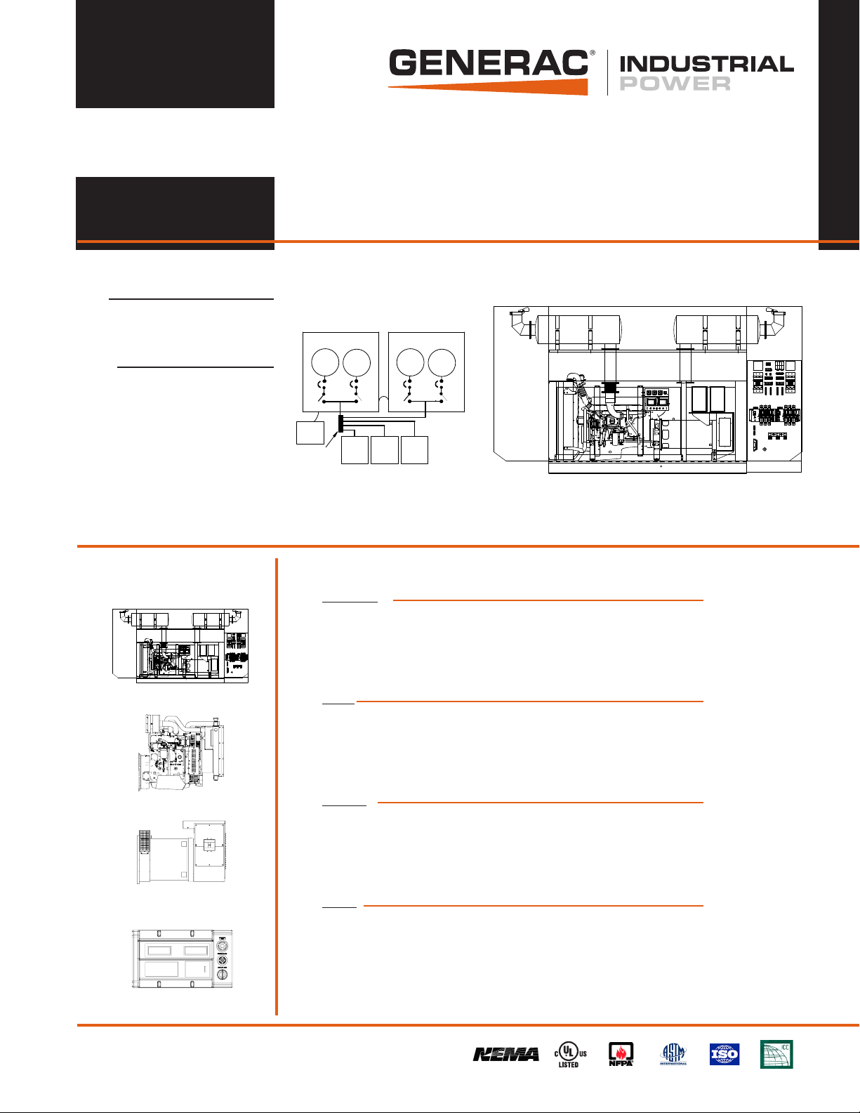
Industrial Diesel Generator Set
PARALLELING UNIT
Standby Power Rating
1250kVA 1000KW 60 Hz
GEMINI
Generator
GEN
Junction
or Conn
Box
Circuit
Breaker
Contactor
GEN
GTS, MTS OR
2- WIRE ATS
Circuit
Breaker
Prime Power Rating*
1125kVA 900KW 60 Hz
Contactor
POWER
MANAGER
SYSTEM
CONTROLLER
*EPA Certified Prime ratings are not available in the U.S. or its Territories for engine model year 2011 and beyond
GTS, MTS OR
2- WIRE ATS
Contactor
GEN
GTS, MTS OR
2- WIRE ATS
GEMINI
Generator
Circuit
Breaker
Contactor
GEN
features benefits
Circuit
Breaker
EPA Certified Stationary Emergency
71 28 87
342164 35 56
P/N:055911
6
6
6
6
7
7
7
767
6
7
7
8
5
8
5
8
4
4
9
9
9
10
32
32
3245
111098
11
1110
1110
111098
111098
0C5139
0C5139
12
0C5137
0C5140
0D5318
0D5318
0C5137
12
121110981212
12
12
12345
1
13245
1
13245
1
SMALL GRAY
LARGE GRAY
LARGE GRAY
LARGE BLACK
LARGE BLACK
LARGE BROWN
1
1
9
235
235
7
7
8
4
6
4
6
ON
11
12
10
5
54 54
4
3
6
3
6
3
6
7
7
7
2
2
2
LO
LO
LO
HI
HI
E
E
E
300
60
800
62
200
400
1200
400
58
100
500
64
0
1600
56
LS-8 CLASS 0.5
LS-8 CLASS 1.5
LS-8 CLASS 1.5
277V
CT. 100:5A
65
55
600
0
0
V
A
Hz
.
.
.
G
G
G
C
C
C
I
I
I
N
N
N
E
E
E
N
N
N
S
S
S
M
M
M
E
E
E
E
E
E
A
A
A
R
R
R
O
O
O
S
S
S
P
P
P
C
C
C
Y
Y
Y
T
T
T
S
R
S
R
S
R
W
W
W
0E9157B
GENERATOR
GENERATOR
EMERGENCY
CONTROL
CONTROL
UNIT B
UNIT A
STOP
ALARM
AUTO OFF MAN.
AUTO OFF MAN.ALARM
ALARM
ALARM
NOT IN AUTO
NOT IN AUTO
Generator image used for illustration purposes only
HI
S1B
S1A A2AT1A1
S1B
S1A A2AT1A1
AT2
AT2
DO NOT OPERATE WHILE THE SWITCH IS UNDER LOAD.
DO NOT OPERATE WHILE THE SWITCH IS UNDER LOAD.
M
M
CLOSE
CLOSE
SET MANUAL HANDLE ON "M" AND
SET MANUAL HANDLE ON "M" AND
OPERATE IN THE DIRECTION
OPERATE IN THE DIRECTION
TRIP OPEN
TRIP OPEN
PUSH THE "TRIP" WITH A SCREWDRIVER
PUSH THE "TRIP" WITH A SCREWDRIVER
T
T
LOAD BREAK SWITCH
LOAD BREAK SWITCH
RATED CURRENT
RATED CURRENT
1000A
1000A
RATED VOLTAGE
RATED VOLTAGE
480 VAC UL
480 VAC UL
600 VAC CSA
600 VAC CSA
xxxxxx
xxxxxx
XXXXX
XXXXX
MANUAL
MANUAL
CLOSE
CLOSE
OFF
TRIP
TRIP
1000 kW Diesel
1 of 5
6
7
6
5
4
3
3245
111098
0C5140
12
12
1
SMALL GRAY
LARGE BROWN
9
8
ON
11
12
10
5
54 54
4
3
6
3
6
3
6
7
7
7
2
2
2
LO
LO
LO
HI
HI
HI
OFF
Generator Set
= CONFIGURED FOR PARALLELING 4 MODULAR PARALLELING SYSTEM
7128 87
34216435 56
P/N:055911
6
6
6
6
6
7
767
7
7
7
6
6
7
7
8
5
8
5
8
5
4
4
9
9
4
9
10
3
3245
3245
32
32
111098
11
111098
111098
111098
1110
1110
0C5139
0C5139
12
12
0C5137
0C5140
0D5318
0D5318
0C5137
0C5140
12
12111098
12
12
12
12
12
12345
13245
1
13245
1
1
1
SMALL GRAY
SMALL GRAY
LARGE GRAY
LARGE GRAY
LARGE BLACK
LARGE BLACK
LARGE BROWN
LARGE BROWN
1
1
9
9
235
235
7
7
8
8
4
6
4
6
ON
ON
11
11
12
12
10
10
5
54 54
5
54 54
4
4
3
3
3
6
3
6
6
3
6
6
3
6
7
7
7
7
7
7
2
2
2
2
2
2
LO
LO
LO
LO
LO
LO
HI
HI
HI
HI
HI
E
E
E
60
300
800
62
200
400
1200
400
58
100
500
64
0
1600
56
LS-8 CLASS 0.5
LS-8 CLASS 1.5
LS-8 CLASS 1.5
277V
CT. 100:5A
65
55
600
0
0
V
A
Hz
.
.
.
G
G
G
C
C
C
I
I
I
N
N
N
E
E
E
N
N
N
S
S
S
M
M
M
E
E
E
E
E
E
A
A
A
R
R
R
O
O
O
S
S
S
P
P
C
P
C
C
Y
Y
Y
T
T
T
S
R
S
R
S
R
W
W
W
GENERATOR
GENERATOR
EMERGENCY
CONTROL
CONTROL
UNIT A
UNIT B
STOP
ALARM
AUTO OFF MAN.
AUTO OFF MAN.ALARM
ALARM
ALARM
NOT IN AUTO
NOT IN AUTO
HI
0E9157B
S1B
S1AA2AT1A1
S1B
S1AA2AT1A1
AT2
AT2
DO NOT OPERATE WHILE THE SWITCH IS UNDER LOAD.
DO NOT OPERATE WHILE THE SWITCH IS UNDER LOAD.
M
M
CLOSE
CLOSE
SET MANUAL HANDLE ON "M" AND
SET MANUAL HANDLE ON "M" AND
OPERATE IN THE DIRECTION
OPERATE IN THE DIRECTION
TRIP OPEN
TRIP OPEN
PUSH THE "TRIP" WITH A SCREWDRIVER
PUSH THE "TRIP" WITH A SCREWDRIVER
T
T
LOAD BREAK SWITCH
LOAD BREAK SWITCH
RATED CURRENT
RATED CURRENT
1000A
1000A
RATED VOLTAGE
RATED VOLTAGE
480 VAC UL
480 VAC UL
600 VAC CSA
600 VAC CSA
xxxxxx
xxxxxx
XXXXX
XXXXX
MANUAL
MANUAL
CLOSE
CLOSE
OFF
OFF
TRIP
TRIP
= UL2200 TESTED 4 ENSURES A QUALITY PRODUCT
= RHINOCOAT PAINT SYSTEM 4 IMPROVES RESISTANCE TO ELEMENTS
= ACOUSTIC ENCLOSURE STANDARD 4 PROVIDES A SINGLE SOURCE SOLUTION
Engines
= EPA COMPLIANT 4 ENVIRONMENTALLY FRIENDLY
= INDUSTRIAL TESTED, GENERAC APPROVED 4 ENSURES INDUSTRIAL STANDARDS
= POWER-MATCHED OUTPUT 4 ENGINEERED FOR PERFORMANCE
= INDUSTRIAL GRADE 4 IMPROVES LONGEVITY AND RELIABILITY
Alternators
= TWO-THIRDS PITCH 4 ELIMINATES HARMFUL 3RD HARMONIC
= LAYER WOUND ROTOR & STATOR 4 IMPROVES COOLING
= CLASS H MATERIALS 4 HEAT TOLERANT DESIGN
= DIGITAL 3-PHASE VOLTAGE CONTROL 4 FAST AND ACCURATE RESPONSE
Controls
= INTEGRATED PARALLELING 4 SINGLE CONTROL MODULE
= 4-20mA VOLTAGE-TO-CURRENT SENSORS 4 NOISE RESISTANT 24/7 MONITORING
= SURFACE-MOUNT TECHNOLOGY 4 PROVIDES VIBRATION RESISTANCE
= ADVANCED DIAGNOSTICS & COMMUNICATIONS 4 HARDENED RELIABILITY
primary codes and standards
Page 2
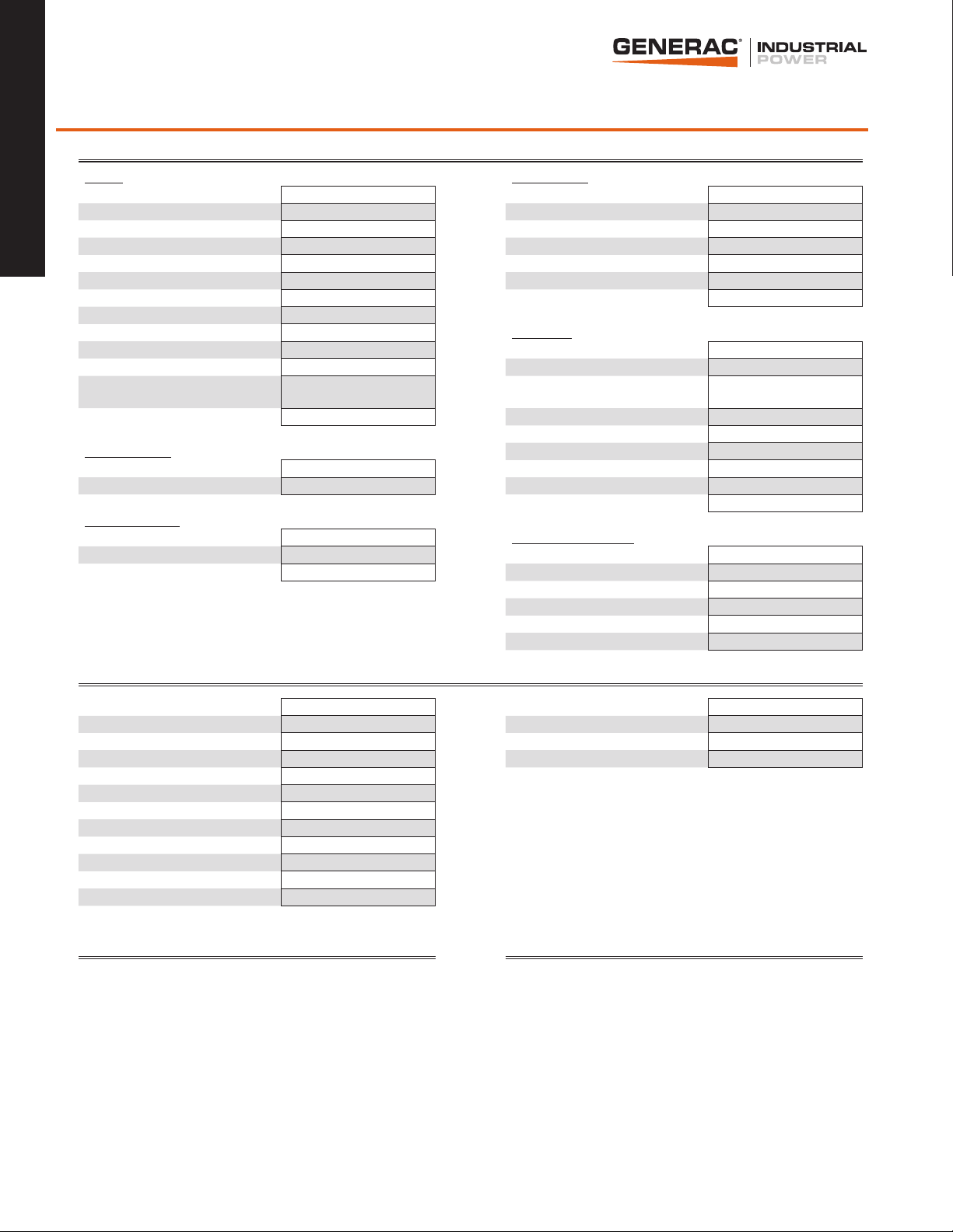
MD1000 application and engineering data
ENGINE SPECIFICATIONS
General Cooling System (each engine)
1000 kW Diesel
2 of 5
Make Generac Cooling System Type Closed Recovery
EPA Emissions Compliance Stationary Emergency Water Pump Prelubed, Self Sealing
EPA Emissions Reference See Emissions Data Sheet Fan Type Pusher
Cylinder # (2) 6 Fan Speed (rpm) 1872
Type In - Line Fan Diameter mm (in.) 889 (35)
Displacement - L (cu. in.) 16.12 (983.7) Coolant Heater Standard Wattage 2x2000W
Bore - mm (in.) 144 (5.67) Coolant Heater Standard Voltage 240VAC
Stroke - mm (in.) 165 (6.5)
Compression Ratio 16.5:1 Fuel System (each engine)
Intake Air Method Turbocharged/Aftercooled Fuel Type Ultra Low Sulfur Diesel Fuel
Cylinder Head Type One Piece Cast Iron Fuel Specifications ASTM
Piston Type
Connecting Rod Type I-Beam Section Fuel Inject Pump Make Delphi
Engine Governing Injector Type Multi-hole, Nozzle Type
Governor Electronic Isochronous Engine Type Direct Injection
Frequency Regulation (Steady State) ± 0.25% Fuel Supply Line - mm (in.) 12.7 (½")
Lubrication System
Oil Pump Type Gear Engine Electrical System (each engine)
Oil Filter Type Full - Flow Cartridge System Voltage 24 VDC
Crankcase Capacity - L (gal) 48 (12.7) Battery Charging Alternator 80 Amps
Aluminum w/ Cooling Cavity,
oil cooled
Fuel Filtering (microns) 10
Fuel Pump Type Engine Driven Gear
Fuel Return Line - mm (in.) 12.7 (½")
Battery Size (at 0ºC) 1155
Battery Group 8D
Battery Voltage (2) - 12 VDC
Ground Polarity Negative
ALTERNATOR SPECIFICATIONS
Standard Model Generac WEG Voltage Regulator Type Digital
Poles 4 Number of Sensed Phases All
Field Type Revolving Regulation Accuracy (Steady State) ± 0.25%
Insulation Class - Rotor H Paralleling Controls Standard
Insulation Class - Stator H
Total Harmonic Distortion < 3%
Telephone Interference Factor (TIF) < 50
Standard Excitation Self-Ventilated, Drip-Proof
Bearings Single Sealed Cartridge
Coupling Direct, Flexible Disc
Load Capacity - Standby 100%
Prototype Short Circuit Test Yes
CODES AND STANDARDS COMPLIANCE (WHERE APPLICABLE) PARALLELING CONTROLS
NFPA 99 BS5514 AUTO-SYNCHRONIZATION PROCESS
NFPA 110 SAE J1349 ISOCHRONOUS LOAD SHARING
ISO 8528-5 DIN6271 REVERSE POWER PROTECTION
ISO 1708A.5 IEEE C62.41 TESTING MAXIMUM POWER PROTECTION
ISO 3046 NEMA ICS 1 ELECTRICALLY OPERATED, MECHANICALLY HELD PARALLELING SWITCH
UL2200 SYNC CHECK SYSTEM
INDEPENDENT ON-BOARD PARALLELING
OPTIONAL PROGRAMMABLE LOGIC FULL AUTO BACK-UP CONTROL (PLS)
Rating Definitions:
Standby – Applicable for a varying emergency load for the duration of a utility power outage with no overload capability. (Max. load factor = 70%)
Prime – Applicable for supplying power to a varying load in lieu of utility for an unlimited amount of running time. (Max. load factor = 80%) A 10% overload capacity is available for 1 out of every
12 hours.
Page 3

MD1000 operating data (60Hz)
POWER RATINGS (kW)
STANDBY PRIME
Three-Phase 277/480VAC @0.8pf 1000 kW Amps: 1505 900 kW Amps: 1355
Three-Phase 346/600VAC @0.8pf 1000 kW Amps: 1204 900 kW Amps: 1084
STARTING CAPABILITIES (sKVA)
sKVA vs. Voltage Dip
480VAC
Alternator kW 10% 15% 20% 25% 30% 35%
Standard (2) 500 914 1371 1829 2286 2743 3200
Upsize 1 - - - - - - -
FUEL
Fuel Consumption Rates* (includes two engines)
STANDBY PRIME
Fuel Pump Lift - mm (in) Percent Load gph lph Percent Load gph lph
1000 (40) 25% 17.4 65.8 25% 15.4 56.6
50% 30.6 115.8 50% 26.8 101.4
75% 45.4 171.8 75% 39.8 150.6
100% 62.6 237.0 100% 56.2 212.8
* Refer to "Emissions Data Sheet" for maximum fuel flow for EPA and SCAQMD permitting purposes.
1000 kW Diesel
3 of 5
COOLING
STANDBY PRIME
Coolant Capacities - Gal (L) Coolant Flow per Minute gpm (lpm) (2) x 122 (462) (2) x 122 (462)
System (2) x 15.9 (60.2) Heat Rejection to Coolant BTU/hr (2) x 1,153,968 (2) x 1,035,991
Engine (2) x 8.78 (33) Inlet Air cfm (m3/min) (2) x 23,308 (660) (2) x 23,308 (660)
Radiator (2) x 7.1 (26.9) Max. Operating Radiator Air Temp Fº (Cº) 122 (50) 122 (50)
Max. Operating Ambient Temperature Fº (Cº) 104 (40) 104 (40)
Maximum Radiator Backpressure in H2O 1.5 1.5
COMBUSTION AIR REQUIREMENTS
STANDBY PRIME
Flow at Rated Power cfm (m3/min) (2) x 1617 (45.8) (2) x 1554 (44.0)
ENGINE
STANDBY PRIME
Rated Engine Speed rpm 1800 1800
Horsepower at Rated kW** hp 757 681
Piston Speed ft/min 1950 1950
BMEP psi 339 302
** Refer to “Emissions Data Sheet” for maximum bHP for EPA and SCAQMD permitting purposes.
EXHAUST
STANDBY PRIME
Exhaust Flow (Rated Output) cfm (m3/min)
Max. Backpressure (Post Silencer) inHg (Kpa) 1.5 (5.1) 1.5 (5.1)
Exhaust Temp (Rated Output) ºF (ºC) 893 (479) 817 (436)
Exhaust Outlet Size (Open Set) (2) x 8" Diameter Exhaust Stack
(2) x 3899
(110.4)
(2) x 3553
(100.6)
Deration – Operational characteristics consider maximum ambient conditions. Derate factors may apply under atypical site conditions. Please consult a Generac Power Systems Industrial Dealer for
additional details. All performance ratings in accordance with ISO3046, BS5514, ISO8528 and DIN6271 standards.
Page 4

MD1000 standard features and options
GENERATOR SET
Genset Vibration Isolation Std
IBC Seismic Certified/Seismic Rated Vibration Isolators Opt
1000 kW Diesel
Extended warranty Opt
Gen-Link Communications Software Opt
4 of 5
Steel Enclosure Std
Aluminum Enclosure Opt
Enclosure Lighting Kits Opt
ENGINE SYSTEM
General
Oil Drain Extensions Std
Oil Make-Up Systems Opt
Oil Heaters Opt
Air cleaners Std
Fan guards Std
Radiator duct adapters Std
Critical Exhaust Silencers Std
Fuel System
Fuel lockoff solenoids Std
Secondary fuel filters Std
Stainless steel flexible exhaust connections Std
Primary fuel filters Opt
Single Wall Tank (Export Only) -
UL 142 Fuel Tank Opt
Cooling System
208VAC Coolant Heaters Opt
240VAC Coolant Heaters Std
Other Coolant Heaters -
Closed Coolant Recovery Systems Std
UV/Ozone resistant hoses Std
Factory-Installed Radiators Std
Radiator Drain Extensions Std
Engine Electrical System
Battery charging alternators Std
Battery cables Std
Battery trays Opt
Battery boxs Opt
Battery heaters Opt
Solenoid activated starter motors Std
10A UL float/equalize battery chargers Opt
Rubber-booted engine electrical connections Std
ALTERNATOR SYSTEM
UL2200 GENprotect™ Std
Main Line Circuit Breakers (Output connections on paralleling switch) Std
Anti-Condensation Heaters Opt
Tropical coating Std
Permanent Magnet Excitation Std
CONTROL SYSTEM
Control Panel
Digital H Control Panel - Dual 4x20 Display na
Digital G-100 Control Panel - Touchscreen na
Digital G-200 Paralleling Control Panel - Touchscreen Std
Programmable Crank Limiter Std
21-Light Remote Annunciator Opt
Remote Relay Panel (8 or 16) Opt
7-Day Programmable Exerciser Std
Special Applications Programmable PLC Std
RS-232 Std
RS-485 Std
All-Phase Sensing DVR Std
Full System Status Std
Utility Monitoring (Req. H-Transfer Switch) Std
2-Wire Start Compatible Std
Power Output (kW) Std
Power Factor Std
Reactive Power Std
All phase AC Voltage Std
All phase Currents Std
Oil Pressure Std
Coolant Temperature Std
Coolant Level Std
Oil Temperature Opt
Fuel Pressure Std
Engine Speed Std
Battery Voltage Std
Frequency Std
Date/Time Fault History (Event Log) Std
Low-Speed Exercise -
Isochronous Governor Control Std
-40deg C - 70deg C Operation Std
Waterproof Plug-In Connectors Std
Audible Alarms and Shutdowns Std
Not in Auto (Flashing Light) Std
Auto/Off/Manual Switch Std
E-Stop (Red Mushroom-Type) Std
Remote E-Stop (Break Glass-Type, Surface Mount) Opt
Remote E-Stop (Red Mushroom-Type, Surface Mount) Opt
Remote E-Stop (Red Mushroom-Type, Flush Mount) Opt
NFPA 110 Level I and II (Programmable) Std
Remote Communication - RS232 Std
Remote Communication - Modem Opt
Remote Communication - Ethernet Opt
PLS Full Auto Back-Up for PM-SC Opt
Alarms (Programmable Tolerances, Pre-Alarms and Shutdowns)
Low Fuel Opt
Oil Pressure (Pre-programmed Low Pressure Shutdown) Std
Coolant Temperature (Pre-programmed High Temp Shutdown) Std
Coolant Level (Pre-programmed Low Level Shutdown) Std
Oil Temperature Std
Engine Speed (Pre-programmed Overspeed Shutdown) Std
Voltage (Pre-programmed Overvoltage Shutdown) Std
Battery Voltage Std
Page 5

MD1000 dimensions, weights and sound levels
LEVEL 1 ACOUSTIC ENCLOSURE
RUN TIME HOURS USABLE CAPACITY (GAL) L W H WT dBA*
NO TANK - 258 96 131 21000
AIR OUT
TOP OF
UNIT
AIR INLETS
SIDE OF UNIT
14 853 258 96 151 25130
25 1578 258 96 160 25630
37 2310 258 96 170 26370
AIR OUT
TOP OF
UNIT
80
1000 kW Diesel
5 of 5
7 128 87
34216 435 56
P/N:055911
6
6
6
6
6
7
767
7
7
7
6
6
7
7
8
5
8
5
8
5
4
4
9
9
4
9
10
3
3245
32
32
3245
111098
11
111098
111098
111098
1110
1110
12
0C5139
0C5139
0C5137
0C5140
0D5318
0D5318
0C5137
0C5140
12
121110981212
12
12
12
12345
12
1
13245
1
13245
1
1
SMALL GRAY
SMALL GRAY
LARGE GRAY
LARGE GRAY
LARGE BLACK
LARGE BLACK
LARGE BROWN
LARGE BROWN
1
1
9
9
8
8
235
235
7
7
4
6
4
6
ON
ON
11
11
12
12
10
10
5
5
4
3
E
E
E
300
60
800
62
200
400
1200
400
58
100
500
64
0
1600
56
LS-8 CLASS 0.5
LS-8 CLASS 1.5
LS-8 CLASS 1.5
CT. 100:5A
277V
65
55
600
0
0
V
A
Hz
.
.
.
I
G
G
I
I
G
N
C
C
C
N
N
E
E
E
M
M
M
S
S
S
N
N
N
E
E
E
E
E
E
A
A
A
O
O
O
S
S
S
R
R
R
P
P
P
Y
Y
Y
C
C
C
R
R
R
S
S
S
T
T
T
W
W
W
0E9157B
GENERATOR
GENERATOR
EMERGENCY
CONTROL
CONTROL
UNIT B
UNIT A
STOP
AUTO OFF MAN.ALARM
AUTO OFF MAN.
ALARM
ALARM
ALARM
NOT IN AUTO
NOT IN AUTO
6
7
2
LO
HI
AT2
S1B
S1A A2AT1A1
DO NOT OPERATE WHILE THE SWITCH IS UNDER LOAD.
M
SET MANUAL HANDLE ON "M" AND
CLOSE
OPERATE IN THE DIRECTION
TRIP OPEN
PUSH THE "TRIP" WITH A SCREWDRIVER
T
LOAD BREAK SWITCH
RATED CURRENT
1000A
RATED VOLTAGE
480 VAC UL
600 VAC CSA
xxxxxx
XXXXX
MANUAL
CLOSE
TRIP
L
545
545
4
4
4
6
3
6
3
7
2
LO
HI
OFF
6
3
6
3
6
3
7
7
7
7
2
2
2
2
LO
LO
LO
LO
HI
HI
HI
HI
AT2
S1B
S1A A2AT1A1
DO NOT OPERATE WHILE THE SWITCH IS UNDER LOAD.
M
SET MANUAL HANDLE ON "M" AND
CLOSE
OPERATE IN THE DIRECTION
TRIP OPEN
PUSH THE "TRIP" WITH A SCREWDRIVER
T
LOAD BREAK SWITCH
RATED CURRENT
1000A
RATED VOLTAGE
480 VAC UL
600 VAC CSA
xxxxxx
XXXXX
MANUAL
CLOSE
OFF
TRIP
H
W
* All measurements are approximate and for estimation purposes only. Weights are without fuel in tank. Sound levels measured at 23ft (7m) and does not account for ambient site conditions.
YOUR FACTORY RECOGNIZED GENERAC INDUSTRIAL DEALER
Tank Options
MDEQ OPT
Florida DERM/DEP OPT
Chicago Fire Code OPT
IFC Certification CALL
ULC CALL
Other Custom Options Available from your Generac Industrial Power Dealer
Specification characteristics may change without notice. Dimensions and weights are for preliminary purposes only. Please consult a Generac Power Systems Industrial Dealer for detailed installation drawings.
Generac Power Systems, Inc. • S45 W29290 HWY. 59, Waukesha, WI 53189 • generac.com
©2012 Generac Power Systems, Inc. All rights reserved. All specifications are subject to change without notice. Bulletin 0173810SBY-D / Printed in U.S.A. 02/28/12
 Loading...